WO2023120055A1 - 形状測定システム及び形状測定方法 - Google Patents
形状測定システム及び形状測定方法 Download PDFInfo
- Publication number
- WO2023120055A1 WO2023120055A1 PCT/JP2022/043879 JP2022043879W WO2023120055A1 WO 2023120055 A1 WO2023120055 A1 WO 2023120055A1 JP 2022043879 W JP2022043879 W JP 2022043879W WO 2023120055 A1 WO2023120055 A1 WO 2023120055A1
- Authority
- WO
- WIPO (PCT)
- Prior art keywords
- optical fiber
- shape
- core optical
- strain
- strain distribution
- Prior art date
- Legal status (The legal status is an assumption and is not a legal conclusion. Google has not performed a legal analysis and makes no representation as to the accuracy of the status listed.)
- Ceased
Links
Images










Classifications
-
- G—PHYSICS
- G01—MEASURING; TESTING
- G01B—MEASURING LENGTH, THICKNESS OR SIMILAR LINEAR DIMENSIONS; MEASURING ANGLES; MEASURING AREAS; MEASURING IRREGULARITIES OF SURFACES OR CONTOURS
- G01B11/00—Measuring arrangements characterised by the use of optical techniques
- G01B11/16—Measuring arrangements characterised by the use of optical techniques for measuring the deformation in a solid, e.g. optical strain gauge
- G01B11/18—Measuring arrangements characterised by the use of optical techniques for measuring the deformation in a solid, e.g. optical strain gauge using photoelastic elements
-
- G—PHYSICS
- G01—MEASURING; TESTING
- G01B—MEASURING LENGTH, THICKNESS OR SIMILAR LINEAR DIMENSIONS; MEASURING ANGLES; MEASURING AREAS; MEASURING IRREGULARITIES OF SURFACES OR CONTOURS
- G01B11/00—Measuring arrangements characterised by the use of optical techniques
- G01B11/16—Measuring arrangements characterised by the use of optical techniques for measuring the deformation in a solid, e.g. optical strain gauge
-
- G—PHYSICS
- G01—MEASURING; TESTING
- G01D—MEASURING NOT SPECIALLY ADAPTED FOR A SPECIFIC VARIABLE; ARRANGEMENTS FOR MEASURING TWO OR MORE VARIABLES NOT COVERED IN A SINGLE OTHER SUBCLASS; TARIFF METERING APPARATUS; MEASURING OR TESTING NOT OTHERWISE PROVIDED FOR
- G01D5/00—Mechanical means for transferring the output of a sensing member; Means for converting the output of a sensing member to another variable where the form or nature of the sensing member does not constrain the means for converting; Transducers not specially adapted for a specific variable
- G01D5/26—Mechanical means for transferring the output of a sensing member; Means for converting the output of a sensing member to another variable where the form or nature of the sensing member does not constrain the means for converting; Transducers not specially adapted for a specific variable characterised by optical transfer means, i.e. using infrared, visible, or ultraviolet light
- G01D5/32—Mechanical means for transferring the output of a sensing member; Means for converting the output of a sensing member to another variable where the form or nature of the sensing member does not constrain the means for converting; Transducers not specially adapted for a specific variable characterised by optical transfer means, i.e. using infrared, visible, or ultraviolet light with attenuation or whole or partial obturation of beams of light
- G01D5/34—Mechanical means for transferring the output of a sensing member; Means for converting the output of a sensing member to another variable where the form or nature of the sensing member does not constrain the means for converting; Transducers not specially adapted for a specific variable characterised by optical transfer means, i.e. using infrared, visible, or ultraviolet light with attenuation or whole or partial obturation of beams of light the beams of light being detected by photocells
- G01D5/353—Mechanical means for transferring the output of a sensing member; Means for converting the output of a sensing member to another variable where the form or nature of the sensing member does not constrain the means for converting; Transducers not specially adapted for a specific variable characterised by optical transfer means, i.e. using infrared, visible, or ultraviolet light with attenuation or whole or partial obturation of beams of light the beams of light being detected by photocells influencing the transmission properties of an optical fibre
- G01D5/3537—Optical fibre sensor using a particular arrangement of the optical fibre itself
- G01D5/3538—Optical fibre sensor using a particular arrangement of the optical fibre itself using a particular type of fiber, e.g. fibre with several cores, PANDA fiber, fiber with an elliptic core or the like
-
- G—PHYSICS
- G02—OPTICS
- G02B—OPTICAL ELEMENTS, SYSTEMS OR APPARATUS
- G02B6/00—Light guides; Structural details of arrangements comprising light guides and other optical elements, e.g. couplings
- G02B6/02—Optical fibres with cladding with or without a coating
- G02B6/02042—Multicore optical fibres
-
- G—PHYSICS
- G02—OPTICS
- G02B—OPTICAL ELEMENTS, SYSTEMS OR APPARATUS
- G02B6/00—Light guides; Structural details of arrangements comprising light guides and other optical elements, e.g. couplings
- G02B6/24—Coupling light guides
- G02B6/42—Coupling light guides with opto-electronic elements
- G02B6/4201—Packages, e.g. shape, construction, internal or external details
- G02B6/4202—Packages, e.g. shape, construction, internal or external details for coupling an active element with fibres without intermediate optical elements, e.g. fibres with plane ends, fibres with shaped ends, bundles
Definitions
- the present disclosure relates to a technique for deriving the three-dimensional shape of a measurement target based on measurement and analysis of the strain distribution in the light propagation direction of a multi-core optical fiber installed along the measurement target.
- MCF Multi Core Fiber
- OFDR Optical Frequency Domain Reflectometry
- FBG Fiber Bragg Grating
- shape identification can also be performed using semi-distribution measurement such as the addition of FBG (see, for example, Non-Patent Document 2).
- FBG semi-distribution measurement
- this technique has a problem that the number of measurement points is limited and shape identification over a long distance is difficult.
- Non-Patent Document 3 uses BOTDR (Brillouin Optical Time Domain Reflectometry) capable of long-distance measurement over several kilometers to several tens of kilometers.
- BOTDR Bacillouin Optical Time Domain Reflectometry
- a core is required at the center of the clad of the MCF, it is not possible to use a 4-core fiber that has no core at the center of the clad and is used for communication applications.
- Non-Patent Document 3 it is necessary to increase the distance between the central core and the outer core for shape sensing with a small curvature.
- the clad diameter is increased in order to widen the core spacing, there arises a problem that the optical fiber tends to break due to bending.
- the present disclosure aims to make it possible to identify the shape of an object to be measured over a long distance using a multi-core optical fiber that does not have a core in the center of the cladding.
- the shape measurement system of the present disclosure A multi-core optical fiber in which four or more cores are arranged in a portion other than the center of the cross section; a strain distribution measuring device for measuring the strain distribution of each core in the longitudinal direction of the multi-core optical fiber; an analysis device that calculates the shape of the multi-core optical fiber using the strain distribution of the multi-core optical fiber; Prepare.
- the shape measurement method of the present disclosure includes: A strain distribution measuring device measures the strain distribution of each core in the longitudinal direction of the multi-core optical fiber using a multi-core optical fiber in which four or more cores are arranged in a portion other than the center of the cross section, An analysis device calculates the shape of the multi-core optical fiber using the strain distribution of the multi-core optical fiber.
- the present disclosure can make it possible to identify the shape of a measurement target over a long distance using a multi-core optical fiber that does not have a core in the center of the cladding.
- FIG. 1 shows an example of a system configuration of the present disclosure; 1 shows an example of a flow executed by a system of the present disclosure; FIG. 4 is an explanatory diagram of curvature ⁇ in the present disclosure; FIG. 4 is an explanatory diagram of distance r, angle ⁇ , and bending angle ⁇ in the present disclosure; 4 shows a first extraction example of three-dimensional shape change in the example embodiment of the present disclosure; 4 shows a first extraction example of three-dimensional shape change in the example embodiment of the present disclosure; 4 shows a first extraction example of three-dimensional shape change in the example embodiment of the present disclosure; 4 shows a second example of extraction of three-dimensional shape change in the example embodiment of the present disclosure; 4 shows a second example of extraction of three-dimensional shape change in the example embodiment of the present disclosure; 4 shows a second example of extraction of three-dimensional shape change in the example embodiment of the present disclosure; 4 shows a second example of extraction of three-dimensional shape change in the example embodiment of the present disclosure; An example of the distance r and the amount of strain generated
- 1 shows a cross-sectional configuration example of a full-type optical fiber.
- 1 shows a cross-sectional configuration example of a hollow optical fiber.
- An example of section modulus versus clad diameter is shown.
- 1 illustrates an example of an MCF for use in example embodiments of the present disclosure
- FIG. 1 shows an example of the system configuration of the present disclosure.
- a system that realizes the shape identification method of the present disclosure includes a multi-core optical fiber 91 used for extracting shape changes of the measurement object 100, and a strain distribution measuring device that detects the strain distribution in the propagation direction of each core 11 of the multi-core optical fiber 91. 92 and an analysis device 93 for analyzing measurement data obtained by the strain distribution measurement device 92 .
- the multi-core optical fiber 91 is installed along the longitudinal direction of the object 100 to be measured.
- the multi-core optical fiber 91 has a total of four cores 11 arranged within the clad 12 .
- the four cores 11 are arranged on a square grid at substantially equal intervals on a substantially identical circle at a distance r from the cross-sectional center of the clad 12, in a region other than the cross-sectional center of the clad 12.
- the four cores 11 are arranged on a square grid at substantially equal intervals on a substantially identical circle at a distance r from the cross-sectional center of the clad 12, in a region other than the cross-sectional center of the clad 12.
- a distance r from the cross-sectional center of the clad 12
- the cores 11 provided in the MCF 91 may have a structure in which the refractive index distribution and optical characteristics of each core are intentionally different.
- the embodiment of the present disclosure shows an example in which the number of cores 11 is four, the number of cores 11 may be four or more.
- the intervals between the cores 11 of the MCF 91 may not be equal, but it is preferable that the cores 11 are arranged evenly to some extent in the cross section of the MCF 91 .
- a core may be arranged in each of four quadrants in the rectangular coordinates.
- FIG. 2 shows an example of the implementation flow of the shape identification method of the present disclosure.
- the MCF 91 is laid on the object 100 to be measured, and the strain distribution characteristic of each core 11 in a steady state is acquired using the strain distribution measuring device 92 (step S1). Thereby, the analysis device 93 acquires the strain distribution in the case of the reference shape. Next, with the three-dimensional shape of the object 100 changed, the strain distribution characteristic of each core 11 is acquired again using the strain distribution measuring device 92 (step S2). Thereby, the analysis device 93 acquires the strain distribution for the unknown shape. Next, using the data acquired in step S1 and the data acquired in step S2, the differential strain in step S2 with respect to step S1 is derived at each point of the MCF 91 where the strain distribution measuring device 92 measures the strain (step S3 ). The differential strain ⁇ i calculated in step S3 is the sum of the strain ⁇ b due to bending of the MCF 91 and the axial strain ⁇ a of the MCF 91 in the longitudinal direction.
- FIG. 4 shows specific examples of the distance r, the angle ⁇ and the bending angle ⁇ .
- the angle ⁇ 1 is an angle between a line connecting the central axis CC of the core C1 and the MCF91 and a line connecting the central axis C4 of the core C4 adjacent to the core C1 and the central axis CC of the MCF91.
- the angles ⁇ 1 to ⁇ 4 are 90 degrees because the cores C1 to C4 are arranged on concentric circles at approximately equal intervals.
- a position vector having a magnitude corresponding to the differential strain ⁇ i in the direction corresponding to the curvature ⁇ and the bending angle ⁇ at each point of the strain measured distance z is determined. (Step S4). As a result, it is possible to determine in what direction and how much the multi-core optical fiber 91 is deformed at each point of the distance z, so that the shape of the multi-core optical fiber 91 after deformation can be measured from the steady state.
- the positional accuracy can be improved.
- BOTDR Optical Frequency Domain Reflectometry
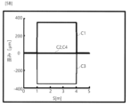
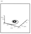
- FIGS. 5A to 5C show examples of extracting three-dimensional shape changes in the embodiment of the present disclosure.
- the strain distribution data in the reference shape in step S1 of FIG. 2 was acquired in a state in which the sensing MCF 91 was linearly stretched.
- the measurement object 100 placed near the center of the MCF 91 is rotated counterclockwise once with a constant curvature on the xy plane, and step S2 is executed.
- strain distribution data for the unknown shape shown in FIG. 5B was acquired.
- the solid lines of C1, C2, C3, and C4 in FIG. 5B represent differences in the core number i.
- 5C shows the results of shape identification by calculating the MCF 91 shape changed from the reference shape based on the strain distribution data in steps S1 and S2. From this result, it can be seen that the bending curvature in the vicinity of the center of the object 100 to be measured can be accurately detected.
- FIGS. 6A to 6C show extraction examples of three-dimensional shape changes in the embodiment of the present disclosure.
- the strain distribution data of the reference shape in step S1 of FIG. 2 was obtained while the sensing MCF 91 was linearly stretched.
- the MCF 91 was deformed from the end of the MCF 91 along the swirling object 100 on the xy plane, and step S2 was executed.
- strain distribution data for the unknown shape shown in FIG. 6B was acquired.
- the solid lines of C1, C2, C3, and C4 in FIG. 6B represent differences in the core number i.
- 6C shows the result of shape identification by calculating the MCF 91 shape changed from the reference shape based on the strain distribution data in steps S1 and S2. From this result, it can be seen that the shape change in which the curvature gradually decreases on the terminal end side of the MCF 91 can be accurately detected.
- FIG. 7 shows an example of strain generated in the core 11 with respect to the distance r.
- the difference in line type in FIG. 7 indicates the difference in curvature, and it can be seen that the farther the core 11 is from the central axis CC of the clad 12, the greater the strain amount, making it easier to extract minute changes. I understand.
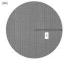
- the diameter of the clad 12 In order to widen the distance r between the central axis CC of the clad 12 and the center of the core 11 in the MCF 91, the diameter of the clad 12 must be increased. As the clad diameter increases, the rigidity of the optical fiber increases, the optical fiber itself is less likely to bend, and the possibility of breakage increases. The rigidity of the optical fiber depends on the cross-sectional shape of the optical fiber. In the case of a solid optical fiber in which the entire optical fiber is made of glass as shown in FIG. be.
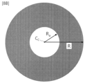
- the core 11 is not required in the clad center axis CC , so a hollow optical fiber in which the center axis CC of the clad 12 is hollow as shown in FIG. 8B is used. becomes possible.
- the section modulus in that case is represented by Equation (4).
- FIG. 8C shows the section modulus with respect to the diameter of the clad 12 calculated using equations (3) and (4).
- Non-Patent Document 3 shows that it is possible to identify the shape of an MCF having a cladding 12 with a diameter of 375 ⁇ m without breaking. It can be seen that if the hollow area is 80%, even if the diameter of the clad 12 is 430 ⁇ m, the rigidity can be kept to the same level as when the diameter of the clad 12 is 375 ⁇ m. Since the present disclosure can utilize a hollow MCF, it is possible to increase the distance r of the core 11 from the clad central axis CC compared to the solid type shown in FIG. 8A. Therefore, the present disclosure makes it possible to detect minute amounts of strain.
- the system configuration of the shape measurement system of this embodiment differs from the configuration described in FIG. 1 in that the MCF 91 is given a known twist, and the analysis procedure of the analysis device 93 accompanying this is different. Specifically, the shape measuring method of this embodiment differs in the analysis of steps S3 and S4 shown in FIG.
- differential strain ⁇ i obtained by taking the difference between the strain distribution of each core 11 of unknown shape and the strain distribution of each core 11 of reference shape is obtained by bending strain ⁇ b,i and axial strain ⁇ It is represented by the sum of a .
- the differential strain ⁇ i is the sum of the bending strain ⁇ b ,i , the axial strain ⁇ a , and the torsional strain ⁇ t .
- the bending strain ⁇ b,i in Equation (1) is expressed by Equation (5), and each coefficient is expressed by (6) to (9).
- k 1 and k 2 are torsion correction coefficients
- ⁇ i is the angle representing the position of the core number i
- ⁇ is the Poisson's ratio
- p is the spin rate of the core 11 on the circumference
- ⁇ is the specific torsion. Show the corners.
- the spin rate is the number of twists [turns/m] applied to the MCF 91 .
- Curvature ⁇ , bending angle ⁇ , axial strain ⁇ a , and torsional strain ⁇ t that satisfy equations (5) and (10 ) are determined by the method of least squares or the like (step S4).
- a position vector having a size corresponding to the multi-core optical fiber differential strain ⁇ i in the direction corresponding to the curvature ⁇ and the bending angle ⁇ at each point of the distance z where the strain was measured is decide.
- shape identification is made possible using a core arrangement structure without a core in the center of a multi-core optical fiber used for shape change detection.
- OFDR enables shape identification of several kilometers or several tens of kilometers instead of several tens of meters.
- a hollow optical fiber can be used for the MCF 91, by increasing the outer diameter of the MCF and increasing the distance between the cladding center and the core center, strain is increased and the strain is minimized. The measurement sensitivity with which the shape can be measured can be improved.
- the present disclosure can be used for infrastructure aging countermeasures by deriving the three-dimensional shape of the measurement target.
Landscapes
- Physics & Mathematics (AREA)
- General Physics & Mathematics (AREA)
- Length Measuring Devices By Optical Means (AREA)
Priority Applications (3)
| Application Number | Priority Date | Filing Date | Title |
|---|---|---|---|
| US18/706,667 US20250060213A1 (en) | 2021-12-24 | 2022-11-29 | Shape measurement system and shape measurement method |
| JP2023569212A JP7637395B2 (ja) | 2021-12-24 | 2022-11-29 | 形状測定システム及び形状測定方法 |
| EP22910773.5A EP4455617A4 (en) | 2021-12-24 | 2022-11-29 | FORM MEASURING SYSTEM AND FORM MEASURING METHOD |
Applications Claiming Priority (2)
| Application Number | Priority Date | Filing Date | Title |
|---|---|---|---|
| JP2021210127 | 2021-12-24 | ||
| JP2021-210127 | 2021-12-24 |
Publications (1)
| Publication Number | Publication Date |
|---|---|
| WO2023120055A1 true WO2023120055A1 (ja) | 2023-06-29 |
Family
ID=86902308
Family Applications (1)
| Application Number | Title | Priority Date | Filing Date |
|---|---|---|---|
| PCT/JP2022/043879 Ceased WO2023120055A1 (ja) | 2021-12-24 | 2022-11-29 | 形状測定システム及び形状測定方法 |
Country Status (4)
| Country | Link |
|---|---|
| US (1) | US20250060213A1 (https=) |
| EP (1) | EP4455617A4 (https=) |
| JP (1) | JP7637395B2 (https=) |
| WO (1) | WO2023120055A1 (https=) |
Cited By (1)
| Publication number | Priority date | Publication date | Assignee | Title |
|---|---|---|---|---|
| WO2025047077A1 (ja) * | 2023-08-28 | 2025-03-06 | 日本電信電話株式会社 | 測定システム、測定方法、及び、解析装置 |
Citations (5)
| Publication number | Priority date | Publication date | Assignee | Title |
|---|---|---|---|---|
| JP2002185063A (ja) * | 2000-12-14 | 2002-06-28 | Hitachi Cable Ltd | 希土類元素添加光ファイバ及びそれを用いた光デバイス |
| US20180109067A1 (en) * | 2016-05-25 | 2018-04-19 | Nec Laboratories America, Inc. | 3d waveguide for efficient coupling of multimode pump and signals to a multicore fiber amplifier |
| JP2018536162A (ja) * | 2015-11-19 | 2018-12-06 | コーニング インコーポレイテッド | マルチコアファイバを使用する分布型ファイバセンサおよびシステム |
| WO2021246497A1 (ja) * | 2020-06-05 | 2021-12-09 | 日本電信電話株式会社 | 形状測定システム及び形状測定方法 |
| WO2022097466A1 (ja) * | 2020-11-05 | 2022-05-12 | 日本電信電話株式会社 | 線状構造物の挙動を算出する装置及び方法 |
Family Cites Families (7)
| Publication number | Priority date | Publication date | Assignee | Title |
|---|---|---|---|---|
| JP2001324358A (ja) * | 2000-05-12 | 2001-11-22 | Fujikura Ltd | 光ファイバセンサ |
| US7930065B2 (en) * | 2005-12-30 | 2011-04-19 | Intuitive Surgical Operations, Inc. | Robotic surgery system including position sensors using fiber bragg gratings |
| US7324714B1 (en) * | 2007-04-11 | 2008-01-29 | The United States Of America As Represented By The Secretary Of The Navy | Multicore fiber curvature sensor |
| US8910391B2 (en) * | 2013-01-24 | 2014-12-16 | Faro Technologies, Inc. | Non-articulated portable CMM |
| JP6346852B2 (ja) * | 2014-11-27 | 2018-06-20 | 日本電信電話株式会社 | 光ファイバの曲げ形状測定装置及びその曲げ形状測定方法 |
| CN114279363B (zh) * | 2016-07-08 | 2025-06-24 | 直观外科手术操作公司 | 用于安全的多芯纤维中冗余弯曲的计算 |
| JP7306565B2 (ja) * | 2020-03-05 | 2023-07-11 | 日本電信電話株式会社 | テープ心線を用いた測定装置及び測定方法 |
-
2022
- 2022-11-29 WO PCT/JP2022/043879 patent/WO2023120055A1/ja not_active Ceased
- 2022-11-29 US US18/706,667 patent/US20250060213A1/en active Pending
- 2022-11-29 EP EP22910773.5A patent/EP4455617A4/en active Pending
- 2022-11-29 JP JP2023569212A patent/JP7637395B2/ja active Active
Patent Citations (5)
| Publication number | Priority date | Publication date | Assignee | Title |
|---|---|---|---|---|
| JP2002185063A (ja) * | 2000-12-14 | 2002-06-28 | Hitachi Cable Ltd | 希土類元素添加光ファイバ及びそれを用いた光デバイス |
| JP2018536162A (ja) * | 2015-11-19 | 2018-12-06 | コーニング インコーポレイテッド | マルチコアファイバを使用する分布型ファイバセンサおよびシステム |
| US20180109067A1 (en) * | 2016-05-25 | 2018-04-19 | Nec Laboratories America, Inc. | 3d waveguide for efficient coupling of multimode pump and signals to a multicore fiber amplifier |
| WO2021246497A1 (ja) * | 2020-06-05 | 2021-12-09 | 日本電信電話株式会社 | 形状測定システム及び形状測定方法 |
| WO2022097466A1 (ja) * | 2020-11-05 | 2022-05-12 | 日本電信電話株式会社 | 線状構造物の挙動を算出する装置及び方法 |
Non-Patent Citations (2)
| Title |
|---|
| KOBAYASHI ET AL.: "Basic Study of Shape Sensing for Large-Scale Line Structures with Multi-Core Fibers by Brillouin OTDR", OFT 2020-19, 2020 |
| See also references of EP4455617A4 |
Cited By (1)
| Publication number | Priority date | Publication date | Assignee | Title |
|---|---|---|---|---|
| WO2025047077A1 (ja) * | 2023-08-28 | 2025-03-06 | 日本電信電話株式会社 | 測定システム、測定方法、及び、解析装置 |
Also Published As
| Publication number | Publication date |
|---|---|
| JP7637395B2 (ja) | 2025-02-28 |
| EP4455617A4 (en) | 2025-12-17 |
| EP4455617A1 (en) | 2024-10-30 |
| JPWO2023120055A1 (https=) | 2023-06-29 |
| US20250060213A1 (en) | 2025-02-20 |
Similar Documents
| Publication | Publication Date | Title |
|---|---|---|
| JP7518243B2 (ja) | 安全性のためのマルチコア光ファイバ内の冗長コア | |
| CN107003473B (zh) | 用于应变和温度分离的多芯光纤中的不同的纤芯 | |
| JP7376052B2 (ja) | 形状測定システム及び形状測定方法 | |
| JP5512462B2 (ja) | 光ファイバおよび光ファイバ線路の曲げ損失の長手方向分布の測定方法、光線路の試験方法および光ファイバの製造方法 | |
| CN103162938B (zh) | 用于表征光纤的光学性质的方法 | |
| JP6346852B2 (ja) | 光ファイバの曲げ形状測定装置及びその曲げ形状測定方法 | |
| Askins et al. | Bend and twist sensing in a multiple-core optical fiber | |
| CN110887448B (zh) | 一种基于光纤应变测量的梁结构形态重构方法 | |
| WO2023120055A1 (ja) | 形状測定システム及び形状測定方法 | |
| WO2021044511A1 (ja) | 光ファイバケーブルセンシング装置、光ファイバケーブルセンシング方法、及びプログラム | |
| JP7306565B2 (ja) | テープ心線を用いた測定装置及び測定方法 | |
| CN120357964A (zh) | 一种应用于光缆的数字孪生模型参数更新方法 | |
| CN110940445A (zh) | 一种光纤环式残余应力测试系统及残余应力测试方法 | |
| Liu et al. | 3D‐Shape Sensing via Monte Carlo‐Optimized Spatial Resolution in Multi‐Channel Parallel OFDR | |
| JP6283602B2 (ja) | 光ファイバの曲げ形状測定装置及びその曲げ形状測定方法 | |
| Askins et al. | Bend and twist sensing in a multi-core optical fiber | |
| JP7406768B2 (ja) | 光ファイバケーブルセンシング装置、光ファイバケーブルセンシング方法、及びプログラム | |
| JP7406767B2 (ja) | 光ファイバケーブルセンシングシステム、光ファイバケーブルセンシング方法、及び光ファイバケーブル | |
| JP2026065458A (ja) | 解析システム、解析装置、及び、解析方法 | |
| Nakamoto et al. | An approach to low-curvature 2D shape sensing using an indoor optical cable | |
| WO2025047077A1 (ja) | 測定システム、測定方法、及び、解析装置 | |
| JP7523071B2 (ja) | 光ファイバ撚り周期算出システム、光ファイバ撚り周期算出方法、光ファイバ撚り周期算出装置及び光ファイバ撚り周期算出プログラム | |
| WO2024228359A1 (ja) | 検出システム、検出方法、及び、解析装置 | |
| JP2023014654A (ja) | 光ファイバ曲げ方向算出システム、光ファイバ曲げ方向算出方法、光ファイバ曲げ方向算出装置及び光ファイバ曲げ方向算出プログラム | |
| Xu et al. | 3d Shape Sensing Based on High-Accuracy Botda Strain Sensor |
Legal Events
| Date | Code | Title | Description |
|---|---|---|---|
| 121 | Ep: the epo has been informed by wipo that ep was designated in this application |
Ref document number: 22910773 Country of ref document: EP Kind code of ref document: A1 |
|
| WWE | Wipo information: entry into national phase |
Ref document number: 2023569212 Country of ref document: JP |
|
| WWE | Wipo information: entry into national phase |
Ref document number: 18706667 Country of ref document: US |
|
| NENP | Non-entry into the national phase |
Ref country code: DE |
|
| ENP | Entry into the national phase |
Ref document number: 2022910773 Country of ref document: EP Effective date: 20240724 |