WO2023119509A1 - フィードスルー構造 - Google Patents
フィードスルー構造 Download PDFInfo
- Publication number
- WO2023119509A1 WO2023119509A1 PCT/JP2021/047638 JP2021047638W WO2023119509A1 WO 2023119509 A1 WO2023119509 A1 WO 2023119509A1 JP 2021047638 W JP2021047638 W JP 2021047638W WO 2023119509 A1 WO2023119509 A1 WO 2023119509A1
- Authority
- WO
- WIPO (PCT)
- Prior art keywords
- cup
- end plate
- space
- insulating liquid
- structure according
- Prior art date
- Legal status (The legal status is an assumption and is not a legal conclusion. Google has not performed a legal analysis and makes no representation as to the accuracy of the status listed.)
- Ceased
Links
Images


Classifications
-
- G—PHYSICS
- G02—OPTICS
- G02B—OPTICAL ELEMENTS, SYSTEMS OR APPARATUS
- G02B6/00—Light guides; Structural details of arrangements comprising light guides and other optical elements, e.g. couplings
- G02B6/44—Mechanical structures for providing tensile strength and external protection for fibres, e.g. optical transmission cables
- G02B6/4439—Auxiliary devices
- G02B6/4471—Terminating devices ; Cable clamps
- G02B6/44775—Cable seals e.g. feed-through
-
- G—PHYSICS
- G02—OPTICS
- G02B—OPTICAL ELEMENTS, SYSTEMS OR APPARATUS
- G02B6/00—Light guides; Structural details of arrangements comprising light guides and other optical elements, e.g. couplings
- G02B6/24—Coupling light guides
- G02B6/42—Coupling light guides with opto-electronic elements
- G02B6/4201—Packages, e.g. shape, construction, internal or external details
- G02B6/4248—Feed-through connections for the hermetical passage of fibres through a package wall
-
- H—ELECTRICITY
- H02—GENERATION; CONVERSION OR DISTRIBUTION OF ELECTRIC POWER
- H02G—INSTALLATION OF ELECTRIC CABLES OR LINES, OR OF COMBINED OPTICAL AND ELECTRIC CABLES OR LINES
- H02G15/00—Cable fittings
- H02G15/08—Cable junctions
-
- H—ELECTRICITY
- H02—GENERATION; CONVERSION OR DISTRIBUTION OF ELECTRIC POWER
- H02G—INSTALLATION OF ELECTRIC CABLES OR LINES, OR OF COMBINED OPTICAL AND ELECTRIC CABLES OR LINES
- H02G15/00—Cable fittings
- H02G15/08—Cable junctions
- H02G15/10—Cable junctions protected by boxes, e.g. by distribution, connection or junction boxes
- H02G15/12—Cable junctions protected by boxes, e.g. by distribution, connection or junction boxes for incorporating transformers, loading coils or amplifiers
- H02G15/14—Cable junctions protected by boxes, e.g. by distribution, connection or junction boxes for incorporating transformers, loading coils or amplifiers specially adapted for submarine cables
Definitions
- the present disclosure relates to feedthrough structures.
- Patent Literature 1 discloses an optical submarine repeater installed on the seabed.
- the optical submarine repeater includes a pressure-resistant housing that can withstand the water pressure of the deep sea, an optical signal amplifier housed in the pressure-resistant housing, and an insulating liquid filled in the pressure-resistant housing.
- Patent Document 1 instead of filling the entire internal space of a pressure-resistant housing with an insulating liquid, only a portion that requires a high dielectric strength, such as an optical signal amplifier, is filled with an insulating liquid. As a result, the amount of insulating liquid used can be reduced.
- Patent Literature 1 proposes that the insulating liquid is filled only in places where high dielectric strength is required, it does not disclose any specific configuration thereof.
- An object of the present disclosure is to provide a technique for realizing insulation between the end face plate of the pressure-resistant housing and the feeder tube with a small amount of insulation liquid.
- an end plate of a pressure-resistant housing, a feeder tube passing through the end plate, a cup attached to the end plate and covering the feeder tube, and an internal space of the cup filled with A feedthrough structure comprising: an insulating liquid;
- FIG. 1 is a schematic diagram of a feedthrough structure; FIG. (First embodiment) It is a front sectional view of an optical repeater.
- (Second embodiment) 1 is a perspective view of a feedthrough structure; FIG. (Second embodiment) FIG. 4 is a cross-sectional view of a feedthrough structure; (Second embodiment) 5 is an enlarged view of part A in FIG. 4; FIG. (Second embodiment) FIG. 4 is a cross-sectional view of a feedthrough structure; (Third embodiment) FIG. 8 is an enlarged view of a B portion in FIG. 7; (Third Embodiment)
- FIG. 1 A schematic diagram of a feedthrough structure 100 is shown in FIG. 1
- the feedthrough structure 100 includes an end plate 101 of a pressure-resistant housing, a feeder tube 102 passing through the end plate 101, a cup 103 attached to the end plate 101 and covering the feeder tube 102, a cup and an insulating liquid 104 filled in the internal space of 103 .
- the insulation between the end plate 101 of the pressure-resistant housing and the feeder tube 102 can be achieved with a small amount of the insulating liquid 104 .
- FIG. 2 shows a sectional view of the optical submarine repeater 1.
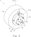
- FIG. 3 shows a perspective view of the feedthrough structure E.
- FIG. 4 shows a cross-sectional view of the feedthrough structure E.
- FIG. 5 is an enlarged view of part A in FIG.
- the optical submarine repeater 1 includes a pressure-resistant housing 2 , an internal unit 3 , two feedthroughs 4 and two tail cables 5 .
- the pressure resistant housing 2 includes a hollow cylinder pressure resistant housing body 10 and two end plates 11 .
- the two end plates 11 are attached to the open end 10 a of the pressure-resistant housing body 10 .
- the two end plates 11 close the open end 10 a of the pressure-resistant housing body 10 .
- Internal unit 3 typically includes an optical signal amplifier for amplifying optical signals.
- the internal unit 3 is housed in the internal space 2 a of the pressure-resistant housing 2 .
- the internal unit 3 is powered by a submarine cable connected to the tail cable 5 .
- Each feedthrough 4 is provided in each end plate 11 and connects each tail cable 5 to the internal unit 3 .
- the end plate 11 is formed into a solid cylinder. As shown in FIG. 4 , the end plate 11 is provided radially inward of the corresponding open end 10 a of the pressure-resistant housing body 10 .
- the end plate 11 includes an end plate body 12 , a cone 13 and a nut 14 .
- the end plate main body 12, the cone 13, and the nut 14 are all made of conductive metal such as beryllium copper (BeCu).
- the end plate main body 12 has an inner surface 12a that defines the internal space 2a of the pressure-resistant housing 2 and an outer surface 12b that faces the opposite side of the inner surface 12a.
- a through hole 15 extending in the axial direction of the pressure-resistant housing 2 is formed in the end plate main body 12 .
- the axial direction means the axial direction of the pressure-resistant housing 2 .
- the radial direction means the radial direction of the pressure-resistant housing 2 .
- the through-hole 15 opens to the inner surface 12a and the outer surface 12b.
- the inner peripheral surface of the through hole 15 is composed of a high-pressure side straight inner peripheral surface 15a, a tapered inner peripheral surface 15b, and a low-pressure side straight inner peripheral surface 15c.
- the straight inner peripheral surface 15a on the high pressure side, the tapered inner peripheral surface 15b, and the straight inner peripheral surface 15c on the low pressure side are continuous in this order from the outer surface 12b toward the inner surface 12a.
- the high pressure side straight inner peripheral surface 15a extends parallel to the axial direction.
- the tapered inner peripheral surface 15 b is tapered toward the inner space 2 a of the pressure-resistant housing 2 .
- the low pressure side straight inner peripheral surface 15c extends parallel to the axial direction.
- the cone 13 is positioned within the through hole 15 of the end plate body 12 .
- the cone 13 has a straight outer peripheral surface 13a, a tapered outer peripheral surface 13b, and a tip surface 13c.
- the straight outer peripheral surface 13a, the tapered outer peripheral surface 13b, and the tip surface 13c are connected in this order from the outer surface 12b toward the inner surface 12a.
- the straight outer peripheral surface 13a extends in parallel with the axial direction and radially faces the high pressure side straight inner peripheral surface 15a.
- the outer diameter of the straight outer peripheral surface 13a is set slightly smaller than the inner diameter of the high pressure side straight inner peripheral surface 15a.
- the tapered outer peripheral surface 13 b is tapered toward the internal space 2 a of the pressure-resistant housing 2 .
- the tapered outer peripheral surface 13b faces the tapered inner peripheral surface 15b in the radial direction.
- the tip surface 13c is orthogonal to the axial direction.
- the outer peripheral edge of the tip surface 13c is positioned at the boundary between the tapered inner peripheral surface 15b of the through hole 15 and the low pressure side straight inner peripheral surface 15c. Therefore, the tip surface 13c is not covered with the end plate main body 12 in the axial direction.
- a through hole 16 extending in the axial direction is formed in the cone 13 .
- the nut 14 is arranged in the through hole 15 of the end plate body 12 .
- the nut 14 is arranged on the high pressure side as seen from the cone 13 .
- a female thread (not shown) formed on the high pressure side straight inner peripheral surface 15 a of the through hole 15 of the end plate body 12
- the tapered outer peripheral surface 13 b of the cone 13 is aligned with the tapered inner peripheral surface of the through hole 15 .
- a through hole 17 extending in the axial direction is formed in the nut 14 .
- the feedthrough 4 includes a penetrating unit 20 , a cup unit 21 and an insulating liquid 22 .
- the penetrating unit 20 includes a feeder tube 23 and an insulating coating 24 .
- the feeding tube 23 is a conductive metal pipe through which the optical fiber F passes, and is made of beryllium copper (BeCu), for example.
- the insulating coating 24 is, for example, an insulating resin such as polyethylene or polyurethane, and covers the outer peripheral surface of the feed pipe 23 .
- the penetrating unit 20 protrudes from the inner surface 12a of the end plate body 12 toward the inner space 2a. An outer peripheral surface 23b of a tip 23a of the feeding tube 23 on the side of the internal space 2a is exposed without being covered with the insulating coating 24. As shown in FIG.
- the penetrating unit 20 penetrates the through hole 15 of the end plate main body 12 . As shown in FIG. 4 , the penetrating unit 20 is arranged to pass through the through hole 16 of the cone 13 and the through hole 17 of the nut 14 .
- the penetrating unit 20 has one end exposed to the internal space 2 a of the pressure-resistant housing 2 and the other end exposed to the external space 2 b of the pressure-resistant housing 2 .
- the cup unit 21 includes a cup body 26, a plurality of fixing bolts 27, a plurality of drain bolts 28, a feeder line 29, and an optical fiber protection tube 30, as shown in FIGS.
- the cup body 26 is one specific example of a cup.
- the cup body 26 is a bottomed cylindrical insulating resin including a hollow cylindrical portion 40 , a flange 41 , and an axially facing portion 42 .
- the hollow cylindrical portion 40 has a hollow cylindrical shape and extends parallel to the axial direction.
- the hollow cylindrical portion 40 is arranged so as to radially face the penetrating unit 20 .
- the hollow cylindrical portion 40 is arranged to annularly cover the penetrating unit 20 .
- the hollow cylindrical portion 40 is arranged so as to annularly cover the exposed tip 23 a of the feeder tube 23 .
- the flange 41 annularly protrudes radially outward from the end portion of the hollow cylindrical portion 40 on the side of the end face plate 11 .
- the hollow cylindrical portion 40 and the flange 41 are constructed integrally.
- the axially facing portion 42 is arranged so as to axially face the tip 23 a of the feeding tube 23 of the penetrating unit 20 and close the open end of the hollow cylindrical portion 40 .
- a plurality of filling holes 42 a are formed in the axially facing portion 42 .
- a drain bolt 28 is attached to each filling hole 42a.
- the axially facing portion 42 is fixed to the hollow cylindrical portion 40 with a plurality of fixing bolts 27 .
- An annular O-ring 43 is provided between the shaft facing portion 42 and the hollow cylindrical portion 40 . This ensures watertightness between the shaft-facing portion 42 and the hollow cylindrical portion 40 .
- the cup body 26 is attached to the inner surface 12 a of the end plate body 12 by a plurality of fixing bolts 27 passing through the flange 41 .
- An O-ring 44 extending annularly is provided between the hollow cylindrical portion 40 and the inner surface 12 a of the end plate main body 12 . As a result, watertightness between the hollow cylindrical portion 40 and the inner surface 12a of the end plate body 12 is ensured.
- the axially facing portion 42 axially faces the end plate body 12 , the cone 13 , and the penetrating unit 20 .
- the axially facing portion 42 extends axially with respect to the hollow cylindrical portion 40, the inner surface 12a of the end plate main body 12, the tip surface 13c of the cone 13, the tip 23a of the feeding tube 23 of the penetration unit 20, and the insulating coating 24. are facing each other. Therefore, in the axial direction, the internal space 26a of the cup main body 26 includes the axially facing portion 42, the inner surface 12a of the end plate main body 12, the tip surface 13c of the cone 13, the tip 23a of the feeding tube 23 of the penetration unit 20, and the insulating coating. 24.
- the internal space 26a of the cup body 26 is defined by a hollow cylindrical portion 40 in the radial direction.
- the power supply line 29 is composed of a core wire 29a and an insulating coating 29b covering the core wire 29a.
- a core wire 29a of the feeder line 29 is connected by brazing to the outer peripheral surface 23b of the tip 23a of the feeder tube 23 exposed in the inner space 26a of the cup body 26 .
- the power supply line 29 passes through a power supply lead-out hole 40 a provided in the hollow cylindrical portion 40 and is drawn out from the internal space 26 a of the cup body 26 . Watertightness between the feeder line 29 and the hollow cylindrical portion 40 is ensured by a self-bonding tape 45 .
- the optical fiber protective tube 30 protects the optical fiber F drawn from the optical fiber drawing hole 42b provided in the axially facing portion 42. As shown in FIG.
- the insulating liquid 22 fills the internal space 26 a of the cup body 26 .
- the insulating liquid 22 is typically insulating oil or fluorine-based inert liquid.
- the insulating liquid 22 is filled into the internal space 26a of the cup body 26 through one of the filling holes 42a of the shaft-facing portion 42 . Further, vacuum defoaming of the insulating liquid 22 may be performed using any of the filling holes 42 a of the shaft-facing portion 42 .
- the feedthrough structure E is composed of at least the end plate 11 , the feeder tube 23 , the cup body 26 and the insulating liquid 22 .
- the feed pipe 23 of the penetration unit 20 and the cone 13 of the end plate 11 are set in a mold, and molten resin is supplied to the mold to form an insulating coating 24 between the feed pipe 23 and the cone 13. do.
- the penetrating unit 20 and the cone 13 are integrated.
- the tail cable 5 is connected to the penetrating unit 20 .
- the penetrating unit 20 and the cone 13 are inserted into the through hole 15 of the end plate main body 12, and the nut 14 is engaged with the straight inner peripheral surface 15a of the through hole 15 on the high pressure side. As a result, watertightness between the cone 13 and the end plate main body 12 is secured annularly.
- the hollow cylindrical portion 40 and flange 41 of the cup body 26 are attached to the inner surface 12 a of the end plate body 12 .
- the core wire 29 a of the power supply line 29 that has been placed in the power supply hole 40 a of the hollow cylindrical portion 40 in advance is brazed to the power supply pipe 23 of the through unit 20 .
- the optical fiber F is pulled out from the optical fiber lead-out hole 42 b of the axially facing portion 42 and then the axially facing portion 42 is attached to the hollow cylindrical portion 40 .
- the inner space 26 a of the cup body 26 is filled with the insulating liquid 22 .
- the feed-through structure E includes the end plate 11 of the pressure-resistant housing 2, the feed pipe 23 passing through the end plate 11, the cup body 26 (cup) attached to the end plate 11 and covering the feed pipe 23, the cup and an insulating liquid 22 filled in an internal space 26 a of the main body 26 .
- the insulation between the end plate 11 of the pressure-resistant housing 2 and the feeding tube 23 can be achieved with a small amount of the insulating liquid 22 .
- the cup body 26 has a bottomed cylindrical shape including a hollow cylindrical portion 40 that annularly covers the feed pipe 23 and an axially facing portion 42 that axially faces the feed pipe 23 .
- the power supply pipe 23 and the axially facing portion 42 face each other with the insulating liquid 22 interposed therebetween in the axial direction. According to the above configuration, insulation between the feeder tube 23 and the shaft-facing portion 42 is ensured.
- the hollow cylindrical portion 40 is provided watertight with respect to the end plate 11 . According to the above configuration, watertightness between the hollow cylindrical portion 40 and the end plate 11 is ensured.
- the end plate 11 and the axially facing portion 42 of the cup body 26 face each other across the insulating liquid 22 in the axial direction. According to the above configuration, insulation between the end plate 11 and the shaft facing portion 42 is ensured.
- the feedthrough structure E further includes a feeder line 29 connected to the feeder tube 23 .
- the power supply line 29 penetrates the insulating liquid 22 and the cup body 26 . According to the above configuration, the insulation between the feeder line 29 and the cup body 26 is ensured within the internal space 26 a of the cup body 26 .
- FIG. 6 shows a cross-sectional view of the feedthrough structure E.
- FIG. 7 is an enlarged view of the B portion of FIG. 6.
- the feedthrough structure E of this embodiment includes end plates 11 of the pressure-resistant housing 2, as in the second embodiment.
- the feedthrough structure E of the present embodiment includes a feeding tube 23 passing through the end plate 11, and a cup body 26 (cup) attached to the end plate 11 and covering the feeding tube 23. , and the insulating liquid 22 filled in the internal space 26 a of the cup body 26 . According to the above configuration, the insulation between the end plate 11 of the pressure-resistant housing 2 and the feeding tube 23 can be achieved with a small amount of the insulating liquid 22 .
- the cup body 26 is a bottomed cylinder having a hollow cylindrical portion 40 that annularly covers the feed pipe 23 and an axially facing portion 42 that axially faces the feed pipe 23. It is an insulating resin with a shape.
- the cup body 26 further divides the internal space 26a in the axial direction into a first space 26b relatively close to the end plate 11 and a second space 26c relatively far from the end plate 11. It has a partition wall 50 .
- the hollow cylindrical portion 40 includes a first cylindrical portion 40b that radially partitions the first space 26b, and a second cylindrical portion 40c that radially partitions the second space 26c.
- a through hole 50 a is formed in the partition wall 50 .
- the feeder pipe 23 is arranged so as to pass through the partition wall 50 .
- An O-ring 53 is provided between the feed pipe 23 and the inner peripheral surface of the through hole 50a. Thereby, the watertightness between the feed pipe 23 and the through hole 50a of the partition wall 50 is ensured.
- An outer peripheral surface 23b of the feeder tube 23 is exposed in the first space 26b.
- the outer peripheral surface 23b of the feeder tube 23 is exposed in the second space 26c.
- the insulating liquid 22 fills the first space 26b and does not fill the second space 26c. This ensures insulation between the outer peripheral surface 23b of the feeder tube 23 exposed in the first space 26b and the inner surface 12a of the end plate body 12 .
- a core wire 29a of the feeder line 29 is brazed to the outer peripheral surface 23b of the tip 23a of the feeder tube 23 in the second space 26c.
- the power supply line 29 is led out from a power supply lead-out hole 40d formed in the second cylindrical portion 40c of the hollow cylindrical portion 40 of the cup body 26. As shown in FIG.
- the power supply line 29 is connected to the power supply pipe 23 in the second space 26c in this way, the distance between the power supply line 29 and the second cylindrical portion 40c of the hollow cylindrical portion 40 in the power supply extraction hole 40d is reduced. No need to ensure watertightness. Similarly, it is not necessary to ensure watertightness between the optical fiber F and the optical fiber drawing hole 42b of the axially facing portion 42. FIG. Therefore, a complicated configuration for ensuring watertightness can be omitted.
- the cup main body 26 is configured by axially connecting a first cup portion 51 made of insulating resin and a second cup portion 52 made of insulating resin.
- the first cup portion 51 has a cylindrical shape with a bottom that forms the first space 26b, and is composed of a first cylindrical portion 40b, a partition wall 50, and a flange 41.
- the second cup portion 52 has a bottomed cylindrical shape that forms the second space 26c, and is composed of a second cylindrical portion 40c and an axially facing portion 42. As shown in FIG.
- the first cup portion 51 is attached to the inner surface 12 a of the end plate main body 12 with a plurality of fixing bolts 27 passing through the flange 41 .
- the second cup portion 52 is connected to the first cup portion 51 by a plurality of fixing bolts 27 .
- the feed pipe 23 of the penetration unit 20 and the cone 13 of the end plate 11 are set in a mold, and molten resin is supplied to the mold to form an insulating coating 24 between the feed pipe 23 and the cone 13. do.
- the penetrating unit 20 and the cone 13 are integrated.
- the tail cable 5 is connected to the penetrating unit 20 .
- the penetrating unit 20 and the cone 13 are inserted into the through hole 15 of the end plate main body 12, and the nut 14 is engaged with the straight inner peripheral surface 15a of the through hole 15 on the high pressure side. As a result, watertightness between the cone 13 and the end plate main body 12 is secured annularly.
- the above is the same as the second embodiment.
- the first cup portion 51 is attached to the inner surface 12 a of the end plate main body 12 using a plurality of fixing bolts 27 .
- the feed pipe 23 passes through the through hole 50 a of the partition wall 50 of the first cup portion 51 .
- the first space 26 b is filled with the insulating liquid 22 through the filling hole provided in the partition wall 50 .
- the core wire 29a of the feeder line 29 is brazed to the feeder pipe 23 of the penetration unit 20, the feeder line 29 is pulled out from the feeder hole 40d of the hollow cylindrical portion 40, and the optical fiber F is connected to the optical fiber of the axially facing portion 42. Pull out from the pull-out hole 42b.
- the second cup portion 52 is attached to the first cup portion 51 using a plurality of fixing bolts 27 .
- the cup body 26 has a bottomed cylindrical shape including a hollow cylindrical portion 40 that annularly covers the feed pipe 23 and an axially facing portion 42 that axially faces the feed pipe 23 .
- the cup body 26 further has a partition 50 that axially divides the inner space 26a into a first space 26b and a second space 26c.
- the feeder pipe 23 is arranged so as to pass through the partition wall 50 .
- the feeding pipe 23 is exposed in the first space 26b and exposed in the second space 26c.
- the insulating liquid 22 fills the first space 26b and does not fill the second space 26c. According to the above configuration, the insulation between the end plate 11 of the pressure-resistant housing 2 and the feeder tube 23 can be achieved with a smaller amount of the insulating liquid 22 .
- the hollow cylindrical portion 40 is provided watertight with respect to the end plate 11 . According to the above configuration, watertightness between the hollow cylindrical portion 40 and the end plate 11 is ensured.
- the end plate 11 and the partition wall 50 face each other with the insulating liquid 22 interposed therebetween in the axial direction. According to the above configuration, insulation between the end plate 11 and the partition wall 50 is ensured.
- the feedthrough structure E further includes a feeder line 29 connected to the feeder tube 23 in the second space 26c.
- the power supply line 29 penetrates the cup body 26 . According to the above configuration, a complicated configuration for ensuring watertightness between the cup body 26 and the feeder line 29 can be avoided.
- the cup body 26 axially connects the bottomed cylindrical first cup portion 51 forming the first space 26b and the bottomed cylindrical second cup portion 52 forming the second space 26c. It consists of According to the above configuration, the core wire 29a of the power supply line 29 can be connected to the outer peripheral surface 23b of the tip 23a of the power supply tube 23 after the first space 26b is filled with the insulating liquid 22, so that assembly workability is excellent.
- the feedthrough structure E is applied to the optical submarine repeater 1 .
- the feedthrough structure E can also be applied to an optical lake bed repeater installed in the lake bed.
- the present disclosure can be applied to electronic devices in general installed on the bottom of the sea or the bottom of a lake.
Landscapes
- Physics & Mathematics (AREA)
- General Physics & Mathematics (AREA)
- Optics & Photonics (AREA)
- Engineering & Computer Science (AREA)
- Power Engineering (AREA)
- Light Guides In General And Applications Therefor (AREA)
Priority Applications (3)
| Application Number | Priority Date | Filing Date | Title |
|---|---|---|---|
| JP2023568898A JP7786752B2 (ja) | 2021-12-22 | 2021-12-22 | フィードスルー構造 |
| US18/716,227 US20250035876A1 (en) | 2021-12-22 | 2021-12-22 | Feed-through structure |
| PCT/JP2021/047638 WO2023119509A1 (ja) | 2021-12-22 | 2021-12-22 | フィードスルー構造 |
Applications Claiming Priority (1)
| Application Number | Priority Date | Filing Date | Title |
|---|---|---|---|
| PCT/JP2021/047638 WO2023119509A1 (ja) | 2021-12-22 | 2021-12-22 | フィードスルー構造 |
Publications (1)
| Publication Number | Publication Date |
|---|---|
| WO2023119509A1 true WO2023119509A1 (ja) | 2023-06-29 |
Family
ID=86901668
Family Applications (1)
| Application Number | Title | Priority Date | Filing Date |
|---|---|---|---|
| PCT/JP2021/047638 Ceased WO2023119509A1 (ja) | 2021-12-22 | 2021-12-22 | フィードスルー構造 |
Country Status (3)
| Country | Link |
|---|---|
| US (1) | US20250035876A1 (https=) |
| JP (1) | JP7786752B2 (https=) |
| WO (1) | WO2023119509A1 (https=) |
Citations (4)
| Publication number | Priority date | Publication date | Assignee | Title |
|---|---|---|---|---|
| JPS57154232U (https=) * | 1981-03-24 | 1982-09-28 | ||
| JPS5983118A (ja) * | 1982-11-05 | 1984-05-14 | Kokusai Denshin Denwa Co Ltd <Kdd> | 光海底中継器用ジヨイントチヤンバ |
| JP2001327061A (ja) * | 2000-05-12 | 2001-11-22 | Mitsubishi Electric Corp | 光回路収納用海底機材 |
| JP2003235149A (ja) * | 2002-02-07 | 2003-08-22 | Mitsubishi Electric Corp | 光ケーブル用海中分岐装置 |
Family Cites Families (3)
| Publication number | Priority date | Publication date | Assignee | Title |
|---|---|---|---|---|
| JPS54104850A (en) * | 1978-02-06 | 1979-08-17 | Nippon Telegr & Teleph Corp <Ntt> | Submarine repeater housing |
| JPS5737314A (en) * | 1980-08-14 | 1982-03-01 | Nec Corp | Casing structure for optical submarine repeater |
| JP5726056B2 (ja) | 2011-12-05 | 2015-05-27 | 日立マクセル株式会社 | 携帯情報端末、その制御方法、及びプログラム |
-
2021
- 2021-12-22 WO PCT/JP2021/047638 patent/WO2023119509A1/ja not_active Ceased
- 2021-12-22 JP JP2023568898A patent/JP7786752B2/ja active Active
- 2021-12-22 US US18/716,227 patent/US20250035876A1/en active Pending
Patent Citations (4)
| Publication number | Priority date | Publication date | Assignee | Title |
|---|---|---|---|---|
| JPS57154232U (https=) * | 1981-03-24 | 1982-09-28 | ||
| JPS5983118A (ja) * | 1982-11-05 | 1984-05-14 | Kokusai Denshin Denwa Co Ltd <Kdd> | 光海底中継器用ジヨイントチヤンバ |
| JP2001327061A (ja) * | 2000-05-12 | 2001-11-22 | Mitsubishi Electric Corp | 光回路収納用海底機材 |
| JP2003235149A (ja) * | 2002-02-07 | 2003-08-22 | Mitsubishi Electric Corp | 光ケーブル用海中分岐装置 |
Also Published As
| Publication number | Publication date |
|---|---|
| JPWO2023119509A1 (https=) | 2023-06-29 |
| JP7786752B2 (ja) | 2025-12-16 |
| US20250035876A1 (en) | 2025-01-30 |
Similar Documents
| Publication | Publication Date | Title |
|---|---|---|
| US4262913A (en) | High pressure gland for optical fibres and/or electrical conductors | |
| US4172212A (en) | Submarine housing for submarine cable system repeater components or the like | |
| AU2015397106B2 (en) | A rigid joint assembly | |
| US6188646B1 (en) | Hydrophone carrier | |
| US11848121B2 (en) | High voltage electric power feed-through apparatus | |
| JPH027245B2 (https=) | ||
| WO2023119509A1 (ja) | フィードスルー構造 | |
| NO343586B1 (en) | Subsea umbilical system with cable breakout | |
| US7180828B1 (en) | Non-kinking oil-filled acoustic sensor stave | |
| GB1389622A (en) | Submarine electric cable | |
| DE1111255B (de) | Wasserdichte und druckfeste Durchfuehrung eines Unterwasserkabels durch die Wand eines druckfest gekapselten Gehaeuses von Unterwasserverstaerkern, Ausgleichsmuffen und aehnlichen Geraeten | |
| EP2586103B1 (en) | Subsea container electrical through connector | |
| JP6989163B2 (ja) | 海底機器、海底機器の構成方法、及び海底ケーブルシステム | |
| JP7593668B2 (ja) | 海底機器、海底機器の構成方法、及び海底ケーブルシステム | |
| CN113851901B (zh) | 一种电气贯穿件及贯穿密封结构 | |
| CN110529666A (zh) | 可拆卸穿舱水密结构 | |
| JP2016181955A (ja) | ケーブルペネトレーション | |
| US2742629A (en) | Metallic coupling means for acoustic logging | |
| AU2014384867B2 (en) | Electrical penetrator assembly | |
| JP2008233302A (ja) | 光ケーブル用光ファイバ収容体 | |
| RU2610921C1 (ru) | Чувствительный элемент для пьезокабельных бортовых гидроакустических антенн | |
| WO2016192779A1 (en) | A rigid joint assembly | |
| JPH061285B2 (ja) | 光ファイバ海底ケーブルのジヨイント構造 | |
| US20150301164A1 (en) | Acoustic module and antenna incorporating said acoustic module | |
| CN119132732A (zh) | 一种矿浆运输复合管缆 |
Legal Events
| Date | Code | Title | Description |
|---|---|---|---|
| 121 | Ep: the epo has been informed by wipo that ep was designated in this application |
Ref document number: 21968946 Country of ref document: EP Kind code of ref document: A1 |
|
| WWE | Wipo information: entry into national phase |
Ref document number: 18716227 Country of ref document: US |
|
| WWE | Wipo information: entry into national phase |
Ref document number: 2023568898 Country of ref document: JP |
|
| NENP | Non-entry into the national phase |
Ref country code: DE |
|
| 122 | Ep: pct application non-entry in european phase |
Ref document number: 21968946 Country of ref document: EP Kind code of ref document: A1 |