WO2023119506A1 - 空気調和機 - Google Patents
空気調和機 Download PDFInfo
- Publication number
- WO2023119506A1 WO2023119506A1 PCT/JP2021/047635 JP2021047635W WO2023119506A1 WO 2023119506 A1 WO2023119506 A1 WO 2023119506A1 JP 2021047635 W JP2021047635 W JP 2021047635W WO 2023119506 A1 WO2023119506 A1 WO 2023119506A1
- Authority
- WO
- WIPO (PCT)
- Prior art keywords
- valve
- refrigerant
- unit
- shutoff
- air conditioner
- Prior art date
- Legal status (The legal status is an assumption and is not a legal conclusion. Google has not performed a legal analysis and makes no representation as to the accuracy of the status listed.)
- Ceased
Links
Images



Classifications
-
- F—MECHANICAL ENGINEERING; LIGHTING; HEATING; WEAPONS; BLASTING
- F25—REFRIGERATION OR COOLING; COMBINED HEATING AND REFRIGERATION SYSTEMS; HEAT PUMP SYSTEMS; MANUFACTURE OR STORAGE OF ICE; LIQUEFACTION SOLIDIFICATION OF GASES
- F25B—REFRIGERATION MACHINES, PLANTS OR SYSTEMS; COMBINED HEATING AND REFRIGERATION SYSTEMS; HEAT PUMP SYSTEMS
- F25B49/00—Arrangement or mounting of control or safety devices
- F25B49/02—Arrangement or mounting of control or safety devices for compression type machines, plants or systems
-
- F—MECHANICAL ENGINEERING; LIGHTING; HEATING; WEAPONS; BLASTING
- F25—REFRIGERATION OR COOLING; COMBINED HEATING AND REFRIGERATION SYSTEMS; HEAT PUMP SYSTEMS; MANUFACTURE OR STORAGE OF ICE; LIQUEFACTION SOLIDIFICATION OF GASES
- F25B—REFRIGERATION MACHINES, PLANTS OR SYSTEMS; COMBINED HEATING AND REFRIGERATION SYSTEMS; HEAT PUMP SYSTEMS
- F25B13/00—Compression machines, plants or systems, with reversible cycle
-
- F—MECHANICAL ENGINEERING; LIGHTING; HEATING; WEAPONS; BLASTING
- F25—REFRIGERATION OR COOLING; COMBINED HEATING AND REFRIGERATION SYSTEMS; HEAT PUMP SYSTEMS; MANUFACTURE OR STORAGE OF ICE; LIQUEFACTION SOLIDIFICATION OF GASES
- F25B—REFRIGERATION MACHINES, PLANTS OR SYSTEMS; COMBINED HEATING AND REFRIGERATION SYSTEMS; HEAT PUMP SYSTEMS
- F25B49/00—Arrangement or mounting of control or safety devices
- F25B49/005—Arrangement or mounting of control or safety devices of safety devices
-
- F—MECHANICAL ENGINEERING; LIGHTING; HEATING; WEAPONS; BLASTING
- F25—REFRIGERATION OR COOLING; COMBINED HEATING AND REFRIGERATION SYSTEMS; HEAT PUMP SYSTEMS; MANUFACTURE OR STORAGE OF ICE; LIQUEFACTION SOLIDIFICATION OF GASES
- F25B—REFRIGERATION MACHINES, PLANTS OR SYSTEMS; COMBINED HEATING AND REFRIGERATION SYSTEMS; HEAT PUMP SYSTEMS
- F25B2313/00—Compression machines, plants or systems with reversible cycle not otherwise provided for
- F25B2313/023—Compression machines, plants or systems with reversible cycle not otherwise provided for using multiple indoor units
- F25B2313/0233—Compression machines, plants or systems with reversible cycle not otherwise provided for using multiple indoor units in parallel arrangements
-
- F—MECHANICAL ENGINEERING; LIGHTING; HEATING; WEAPONS; BLASTING
- F25—REFRIGERATION OR COOLING; COMBINED HEATING AND REFRIGERATION SYSTEMS; HEAT PUMP SYSTEMS; MANUFACTURE OR STORAGE OF ICE; LIQUEFACTION SOLIDIFICATION OF GASES
- F25B—REFRIGERATION MACHINES, PLANTS OR SYSTEMS; COMBINED HEATING AND REFRIGERATION SYSTEMS; HEAT PUMP SYSTEMS
- F25B2500/00—Problems to be solved
- F25B2500/22—Preventing, detecting or repairing leaks of refrigeration fluids
- F25B2500/221—Preventing leaks from developing
-
- F—MECHANICAL ENGINEERING; LIGHTING; HEATING; WEAPONS; BLASTING
- F25—REFRIGERATION OR COOLING; COMBINED HEATING AND REFRIGERATION SYSTEMS; HEAT PUMP SYSTEMS; MANUFACTURE OR STORAGE OF ICE; LIQUEFACTION SOLIDIFICATION OF GASES
- F25B—REFRIGERATION MACHINES, PLANTS OR SYSTEMS; COMBINED HEATING AND REFRIGERATION SYSTEMS; HEAT PUMP SYSTEMS
- F25B2500/00—Problems to be solved
- F25B2500/22—Preventing, detecting or repairing leaks of refrigeration fluids
- F25B2500/222—Detecting refrigerant leaks
Definitions
- An embodiment of the present invention relates to an air conditioner.
- Patent Literature 1 discloses an air conditioner in which a shutoff valve, which is an electromagnetic valve, is provided in a refrigerant pipe connecting an indoor unit and an outdoor unit.
- shutoff valve By the way, if the operating speed of the shutoff valve is slow, the refrigerant cannot be shut off quickly. Therefore, it is desirable to operate the shut-off valve as fast as possible.
- the drive torque of the motor becomes small, and the drive output to the motor and the opening of the shutoff valve are deviated, making it difficult to operate the shutoff valve accurately. and may not be able to close completely.
- An air conditioner includes an outdoor unit, an indoor unit connected to the outdoor unit by a refrigerant pipe, a blocking unit capable of blocking the flow of refrigerant in the refrigerant pipe between the outdoor unit and the indoor unit, and a refrigerant leak. and a refrigerant leakage detection unit that detects the
- the shut-off unit includes a shut-off valve that shuts off the flow of refrigerant in the refrigerant pipe, and a controller that controls the operation of the shut-off valve.
- the shut-off valve is an electrically operated valve driven by a motor, and the control unit closes the shut-off valve at the operation speed (v1) when the refrigerant leakage detection unit detects a refrigerant leak, and then closes the shut-off valve. is controlled to be retightened at an operating speed (v2) slower than the operating speed (v1).
- FIG. 1 is a diagram schematically showing a schematic configuration example of an air conditioner according to an embodiment
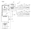
- a diagram schematically showing an electrical configuration example of an air conditioner A diagram schematically showing a cross section of a configuration example of a motor-operated valve Control flow chart of the valve control section Control flowchart of the indoor control unit and refrigerant leak detection unit
- a diagram schematically showing another schematic configuration example of the air conditioner A diagram schematically showing a cross section of a configuration example of another motor-operated valve
- the air conditioner 1 of the present embodiment has a so-called multi-type configuration, in which one outdoor unit 2, for example, three indoor units 3A, 3B and 3C are installed. , are connected by a first pipe 6 and a second pipe 7 as refrigerant pipes through which a refrigerant flows.
- a refrigerating cycle connected by the first pipe 6 and the second pipe 7 is filled with a flammable refrigerant, for example, a mildly flammable refrigerant such as HFC-R32.
- the air conditioner 1 includes a blocking unit 4 capable of blocking the flow of refrigerant between the outdoor unit 2 and the indoor unit 3 and a power storage unit 5 .
- the indoor units 3 are simply referred to as the indoor units 3 without adding A, B, and C when describing the common indoor units 3 .
- the power supply path from the external power supply 8 to the outdoor unit 2, the indoor unit 3, and the cutoff unit 4 is schematically shown by a relatively thick solid line, and the power supply from the power storage unit 5 to the cutoff unit 4 is schematically indicated by a relatively thick dashed line.
- the outdoor unit 2 includes an outdoor heat exchanger 21, an outdoor expansion valve 22, an outdoor fan 23, a four-way valve 24, a compressor 25, and the like.
- the configuration of the outdoor unit 2 shown in FIG. 1 is an example, and for example, it can be configured to include an accumulator, a pressure sensor, and the like.
- the number of indoor units 3 may be one or more, and a plurality of outdoor units 2 may be connected in parallel on the refrigeration cycle.
- the indoor unit 3 includes an indoor controller 30, an indoor heat exchanger 31, an indoor expansion valve 32 provided on the first pipe 6 side of the indoor heat exchanger 31, an indoor fan 33, and the like.
- the indoor control unit 30 is configured by a microcomputer (not shown), and controls the operation of the indoor unit 3 such as starting and stopping of operation, and the associated operations of the indoor expansion valve 32 and the indoor fan 33 .
- the indoor control unit 30 is connected to an operation panel (not shown), a so-called remote control device, for inputting operation start and stop operations, setting and displaying the temperature of the air-conditioned space 100, and responding to the instructions thereof.
- the air conditioner 1 is controlled accordingly.
- the indoor control unit 30 is connected to a refrigerant leakage detection unit 30a.
- the refrigerant leakage detection unit 30a includes a gas sensor 9 that detects a flammable refrigerant in the air, and when a signal indicating that the refrigerant has been detected is input from the gas sensor 9, the refrigerant leakage detection unit 30a detects the refrigerant in the indoor unit. It is determined that refrigerant leakage has occurred in the vicinity of 3 .
- a buzzer 60 as a sound output unit is connected to the refrigerant leakage detection unit 30a, and the refrigerant leakage detection unit 30a sounds the buzzer 60 when refrigerant leakage is detected as described later. This buzzer 60 can also be provided in the indoor controller 30, as will be described later with reference to FIG.
- the indoor unit 3 is provided with the gas sensor 9.
- the gas sensor 9 is installed, for example, at a low position in the air-conditioned space 100 in order to detect the refrigerant, which is generally considered heavier than air.
- the indoor control unit 30 and the refrigerant leakage detection unit 30a may be connected by a signal cable or the like.
- three indoor units 3A, 3B and 3C are connected in parallel to a single refrigerant piping system. Further, in this embodiment, it is assumed that the three indoor units 3A-3C respectively air-condition the air-conditioned spaces 100a-100c.
- a refrigeration cycle for air-conditioning the air-conditioned space 100 is constructed by the outdoor unit 2, the indoor unit 3, and the refrigerant piping system.
- the configuration of the refrigeration cycle, the number of indoor units 3 connected to the refrigerant piping system, the number of air-conditioned spaces 100, or the number of indoor units 3 installed in the air-conditioned spaces 100 shown in FIG. is not limited to
- one air-conditioned space 100 can be air-conditioned by a plurality of indoor units 3 .
- the air conditioner 1 passes the refrigerant discharged from the compressor 25 through the outdoor heat exchanger 21, the outdoor expansion valve 22, and the first pipe 6 to the indoor unit 3 as indicated by the solid arrow C. , and the four-way valve 24 is switched so that the refrigerant flowing out from the indoor unit 3 returns to the compressor 25 via the second pipe 7 .
- the air conditioner 1 supplies the refrigerant discharged from the compressor 25 to the indoor unit 3 via the second pipe 7 as indicated by the dashed arrow H, and the indoor unit 3
- the four-way valve 24 is switched so that the refrigerant flowing out from the outside returns to the outdoor heat exchanger 21 via the indoor expansion valve 32 , the first pipe 6 and the outdoor expansion valve 22 .
- the switching of the four-way valve 24 and the operation of the compressor 25 are controlled by an outdoor controller (not shown) that controls the refrigerating cycle according to instructions from each indoor controller 30 .
- the shutoff unit 4 is composed of a plurality of shutoff valves 41 capable of shutting off the refrigerant flow between the outdoor unit 2 and the indoor unit 3, and a valve control section 42 that controls the operation of the shutoff valves 41.
- the shut-off valve 41 is a so-called electrically operated valve driven by a motor, and its opening can be adjusted.
- An electric valve driven by such a motor is also called a PMV (Pulse Motor Valve).
- the shutoff valves 41 are provided on the first pipe 6 side and the second pipe 7 side of each indoor unit 3, respectively. Specifically, a cutoff valve 41A1 is provided between the indoor expansion valve 32A and the outdoor expansion valve 22 on the side of the first pipe 6 of the indoor unit 3A, and the indoor heat exchanger 31A on the side of the second pipe 7. and the four-way valve 24, a cutoff valve 41A2 is provided.
- a cutoff valve 41B1 is provided between the indoor expansion valve 32B and the outdoor expansion valve 22 on the side of the first pipe 6 of the indoor unit 3B, and the indoor heat exchanger 31B is provided on the side of the second pipe 7.
- a cutoff valve 41B2 is provided between the four-way valve 24 and the four-way valve 24 .
- a cutoff valve 41C1 is provided between the indoor expansion valve 32C and the outdoor expansion valve 22, and on the side of the second pipe 7, the indoor heat exchanger 31C
- a cutoff valve 41C2 is provided between the valve 24 and the valve 24 .
- each indoor unit 3 is connected to the outdoor unit 2 by three refrigerant pipes.
- three shutoff valves 41 are required for each indoor unit 3, which is the same as the number of refrigerant pipes.
- shutoff valves 41 By closing these shutoff valves 41, the air conditioner 1 allows the refrigerant to flow between the first pipe 6 and the indoor unit 3 and between the second pipe 7 and the indoor unit 3. can be blocked. As a result, the corresponding indoor unit 3 can be disconnected from the refrigeration cycle.
- the shutoff valves 41 are simply referred to as the shutoff valves 41 without adding A1 or the like when describing the common shutoff valves 41 .
- the operations of these shutoff valves 41 are controlled by a valve control section 42 .
- the valve control unit 42 is configured by a microcomputer (not shown) or the like, and executes processing for controlling the operation of the cutoff valve 41 .
- the valve control section 42 controls the operation of each shutoff valve 41 provided in each indoor unit 3 . That is, in the present embodiment, a common cutoff unit 4 is provided for a plurality of indoor units 3 connected in parallel to a single refrigerant piping system, and is provided corresponding to each indoor unit 3. The operation of each shutoff valve 41 is centrally controlled by a common valve control unit 42 as shown in FIG.
- valve control unit 42 corresponding to each indoor unit 3 may be provided. It is also possible to install the controller 42 in combination. 2 except for the external power supply 8 and the indoor unit 3 is the cutoff unit 4. As shown in FIG.
- the valve control unit 42 is connected to the indoor control unit 30 by a communication line 42c to enable mutual exchange of signals.
- the indoor controller 30 issues to the valve controller 42 a refrigerant leakage detection signal (to be described later) and an instruction to open the closed cutoff valve 41 .
- the valve control unit 42 includes a power cutoff detection unit 42a that detects cutoff of power supply from the external power source 8.
- the power cut-off detection unit 42 a is realized by combining a voltage detector of the external power supply 8 and software by executing a program in the valve control unit 42 .
- the power cutoff detection unit 42a monitors the supply of power from the external power supply 8, and determines that the supply of power from the external power supply 8 has been cut off when the supply of power from the external power supply 8 is stopped. do. This state is hereinafter referred to as power shutdown. It is assumed that the power shutdown occurs due to, for example, a power failure, damage to the power supply path, or erroneous tripping of a breaker.
- the electric storage unit 5 is connected to the valve control unit 42 by a signal line 42b, and supplies electric power to the cutoff unit 4 when the external power source 8 is cut off due to a power failure or the like. Specifically, while power is being supplied from the external power supply 8, the power storage unit 5 is always charged with the power supplied from the external power supply 8 and stores the power. Based on the activation command from the valve control section 42 output via the signal line 42b, the stored electric power is supplied to the valve control section 42 and the cutoff valve 41 of the cutoff unit 4. FIG. For this reason, the shutoff unit 4 is configured so that the valve control section 42 and the shutoff valve 41 can operate even when the power is shut off.
- a backup power supply circuit (not shown) such as a large-capacity capacitor is provided to enable operation of the valve control unit 42 during the period from when the external power supply 8 is cut off to when the electric power supply from the storage unit 5 is started.
- a backup power supply circuit such as a large-capacity capacitor is provided to enable operation of the valve control unit 42 during the period from when the external power supply 8 is cut off to when the electric power supply from the storage unit 5 is started.
- power is supplied to the shutoff valve 41 when the external power supply 8 is cut off. It can also be configured to switch to .
- FIG. 1 exemplifies a configuration in which one power storage unit 5 is provided for the shutoff unit 4, for example, one power storage unit 5 may be provided for each shutoff valve 41, or as shown in FIG. A plurality of power storage units 5 may be provided for the air conditioner 1 , such as one power storage unit 5 for each indoor unit 3 .
- the shut-off valve 41 is a motor-operated valve, also called a pulse motor valve, which controls opening and closing by rotation of a motor, unlike a so-called solenoid valve. For this reason, the shutoff valve 41 operates at a slower speed when closing the flow path than a general electromagnetic valve. This is due to the structure of the shut-off valve 41, as explained below.
- operation speed means, in a technical sense, the time required to close an open channel or the time required to open a closed channel. For example, the shorter the time required to close the channel, the faster the operating speed, and the longer the time required to close the channel, the slower the operating speed.
- the shutoff valve 41 includes a valve body 41c having a first connecting end 41a serving as an inlet or outlet for the refrigerant and a second connecting end 41b serving as an outlet or inlet for the refrigerant.
- first connecting end 41a serving as an inlet or outlet for the refrigerant
- second connecting end 41b serving as an outlet or inlet for the refrigerant.
- first connection end 41a serves as the refrigerant inlet
- the second connection end 41b serves as the refrigerant outlet
- the second connection end 41b serves as the refrigerant outlet.
- the valve body 41c is formed with a hollow valve seat 41d that is a cylindrical opening connected to the second connection end 41b.
- the valve body 41c is arranged coaxially with the valve seat 41d, and accommodates a valve stem 41e that is relatively movable along the vertical direction in the figure with respect to the valve body 41c.
- the valve stem 41e has a male-threaded surface on the lower end side in the figure, and is passed through a bearing portion 41f, which is fixed to the valve body 41c and has a female-threaded portion through which the valve stem 41e passes.
- valve stem 41e in the figure is fixed to the rotor 41h of the pulse motor 41g.
- the rotor 41h is a rotor having a plurality of magnetic poles, and is rotatable integrally and coaxially with the valve stem 41e and slidable in the vertical direction in the drawing with respect to the case body 41i.
- the upper end side of the case body 41i in the figure is closed by a lid member 41j. Further, the case body 41i is provided with a stator 41k of a pulse motor 41g positioned on the outer circumference of the range in which the rotor 41h can slide. As is well known, the stator 41k is formed of a coil 41l, and as shown in FIG.
- the cutoff valve 41 When a control signal is input from the valve control unit 42 side, the cutoff valve 41 having such a configuration outputs a predetermined energizing pulse to the pulse motor 41g, whereby the rotor 41h having magnetic poles rotates together with the valve stem 41e. Since the male threaded portion in the middle of the valve stem 41e is inserted into the female threaded portion of the bearing portion 41f, the valve stem 41e moves along the vertical direction in the figure as the valve stem 41e rotates.
- illustration of a drive circuit configured by, for example, a transistor bridge for driving the pulse motor 41g is omitted.
- the valve stem 41e is arranged at a position coaxial with the valve seat 41d, and the tip of the valve stem 41e on the lower side in the drawing is formed in, for example, a wedge shape that can be inserted into and removed from the valve seat 41d. .
- the tip of the valve stem 41e is inserted into the valve seat 41d and the valve seat 41d is blocked by the valve stem 41e, the coolant flow path between the first connecting end 41a and the second connecting end 41b is blocked.
- This state corresponds to a state in which the cutoff valve 41 is closed.
- the position of the valve stem 41e when the cutoff valve 41 is closed will be referred to as the closed position.
- valve stem 41e when the valve stem 41e is slightly pulled upward in the drawing from the closed position, a flow path for the refrigerant is slightly formed at the valve seat 41d. This flow path becomes larger as the valve stem 41e is pulled upward in the drawing, and becomes maximum when the valve stem 41e is completely pulled out from the valve seat 41d.
- the opening degree of the cutoff valve 41 can be adjusted by the position of the valve stem 41e.
- the position of the valve rod 41e pulled up to the upper limit on the upper side of the drawing is referred to as the open position.
- the air conditioner 1 includes a shutoff valve 41 capable of shutting off the flow of refrigerant in the refrigerant piping system. Therefore, for example, when refrigerant leakage into the air-conditioned space 100 is detected, it is possible to block the flow of refrigerant flowing into the indoor unit 3 and the flow of refrigerant flowing out of the indoor unit 3 . As a result, further refrigerant leakage is suppressed, and it is considered that the safety in the air-conditioned space 100 can be ensured.
- the air conditioner 1 needs to operate the cutoff valve 41 to cut off the flow of the refrigerant not only when refrigerant leakage is detected but also when the power supply from the external power supply 8 is cut off. . Therefore, the electric storage unit 5 is provided in the air conditioner 1, and when the external power supply 8 is cut off, the valve control unit 42 and the cutoff valve 41 are operated for a certain period of time to cut off the refrigerant flow. .
- shutoff valve 41 When closing the shutoff valve 41, if the operating speed of the shutoff valve 41 is slow, it may not be possible to quickly shut off the refrigerant. Therefore, it is desirable to operate the cutoff valve 41 at the highest possible speed.
- the shutoff valve 41 that is driven to open and close using a motor, power consumption increases when the motor is driven at high speed. As a result, the supply of electric power from the external power source 8 is cut off, and when the cutoff valve 41 is operated using the electric power of the electric storage unit 5, the charging power of the electric storage unit 5 is reduced by the power consumption when the motor is driven. decreases sharply. Therefore, if the shutoff valve 41 is repeatedly closed in a short period of time, the amount of charge in the electric storage unit 5 may decrease, and the shutoff valve may not be operated.
- shutoff valve 41 driven by the motor is operated at a high speed, the driving torque of the motor becomes small, and the shutoff valve 41 cannot be operated accurately and may not be completely closed.
- the pulse output speed of the pulse signal output from the valve control unit 42 is high, even if the signal of the required number of pulses is output from the valve control unit 42, the rotation of the rotor 41h cannot respond, resulting in a so-called pulse output. There is a risk that disconnection will occur and the shutoff valve 41 will not operate to the closed position.
- the valve control unit 42 executes the processing shown in the flowchart of FIG. 4 so that the refrigerant can be cut off quickly and reliably depending on the situation. To put it simply, the air conditioner 1 reduces the possibility that the cutoff valve 41 cannot be operated, and allows the refrigerant to be cut off quickly.
- the processing of the valve control unit 42 shown in FIG. 4 includes detection of power shutdown by the power shutdown detection unit 42a.
- FIG. 5 shows the processes of the indoor control unit 30 and the refrigerant leakage detection unit 30a that are linked with the valve control unit 42, respectively.
- the valve control unit 42 determines whether or not a refrigerant leakage signal has been received (S1). A determination is made as to whether or not a cutoff has been detected (S7).
- the reception of the refrigerant leakage signal means that the refrigerant leakage detection unit 30a detects the refrigerant leakage into the room, outputs the refrigerant leakage detection signal to the indoor control unit 30, and This means that the control unit 30 transmits a refrigerant leakage signal indicating detection of refrigerant leakage to the valve control unit 42 via the communication line 42c, and the valve control unit 42 receives the refrigerant leakage signal.
- a refrigerant leakage detection unit 30a detection of refrigerant leakage is performed by a refrigerant leakage detection unit 30a. That is, it is determined whether or not it has been detected (S11).
- the refrigerant gas is a gaseous refrigerant sealed in the refrigeration cycle that has leaked from the indoor unit 3 or pipes in the vicinity thereof.
- the refrigerant leakage detection unit 30a proceeds to step S11 to continue detection of the refrigerant gas. do.
- the refrigerant leakage detection unit 30a transmits a refrigerant leakage detection signal to the indoor control unit 30 (S12), and sounds the buzzer 60 to give an alarm. A sound is produced (S13).
- the refrigerant leakage detection unit 30a performs the process of transmitting the refrigerant leakage detection signal before the process of ringing the buzzer 60 in order to cut off the refrigerant leakage as soon as possible.
- a speaker that outputs a sound corresponding to an input signal may be used.
- the sound output section may be anything as long as it can output sound.
- a light-emitting element such as an LED may be provided so as to emit light in conjunction with the buzzer 60 so that the alarm can be visually recognized.
- the refrigerant leakage detection unit 30a determines whether a reset operation has been performed or whether a reset signal has been received (S14).
- This reset operation or reset signal is input or transmitted by the operation of the maintenance and inspection operator after the refrigerant leakage has been dealt with and the refrigerant leakage has been eliminated. Therefore, when the reset operation is not performed and the reset signal is not received (S14: NO), the refrigerant leakage detection unit 30a repeats the step S14 to keep the buzzer 60 sounding, and the reset operation or the reset signal waiting for the reception of
- the coolant leakage detection unit 30a stops the buzzer 60 (S15), returns, and returns to the initial state. to determine whether the refrigerant leakage signal has been received again. In this way, when the refrigerant leakage detection unit 30a detects refrigerant leakage, the refrigerant leakage detection unit 30a transmits the refrigerant leakage detection signal to the indoor control unit 30 once, and measures against the refrigerant leakage are performed to eliminate the refrigerant leakage. The buzzer 60 continues to sound until safety is confirmed.
- the indoor control unit 30 determines whether or not the refrigerant leakage detection signal is received from the refrigerant leakage detection unit 30a (S21), and if the refrigerant leakage detection signal is not received (S21: NO), The normal operation process is executed (S25), and the process proceeds to step S21 to continue monitoring reception of the refrigerant leakage detection signal.
- the normal operation processing includes displaying the temperature in the air-conditioned space 100, accepting operations such as setting changes, and communicating with the outdoor unit 2. FIG.
- the indoor controller 30 receives the refrigerant leakage detection signal (S21: YES), it transmits the refrigerant leakage signal to the cutoff unit 4 (S22).
- This refrigerant leakage signal is a signal for notifying the cutoff unit 4 that refrigerant leakage has been detected.
- the indoor control unit 30 determines whether an opening instruction has been input (S23). This opening instruction input is given by, for example, a user's operation or a host control device after the maintenance and inspection operator has taken action against the refrigerant leakage, eliminated the refrigerant leakage, and confirmed safety. If there is no opening instruction input (S23: NO), the indoor control unit 30 waits. ) return. In this way, the indoor control unit 30 and the refrigerant leakage detection unit 30a detect the refrigerant, and the cutoff unit 4 is notified of the detection result.
- This opening instruction input is given by, for example, a user's operation or a host control device after the maintenance and inspection operator has taken action against the refrigerant leakage, eliminated the refrigerant leakage, and confirmed safety. If there is no opening instruction input (S23: NO), the indoor control unit 30 waits. ) return. In this way, the indoor control unit 30 and the refrigerant leakage detection unit 30a detect the refrigerant, and the cutoff unit 4
- the shutoff unit 4 controls the shutoff valve 41 to close. Specifically, as shown in FIG. 4, when the valve control unit 42 of the shutoff unit 4 determines that the power shutoff has not been detected (S7: NO), whether the shutoff valve 41 is closed or not. It is determined whether or not (S4). When the valve control unit 42 determines that the shutoff valve 41 is closed (S4: YES), it determines whether an opening instruction to open the shutoff valve 41 has been given (S5). It should be noted that YES in step S4 means that refrigerant leakage has already been detected or power failure has been detected. Further, whether or not the shutoff valve 41 is closed is determined by the valve control unit 42 storing the operation result of either opening or closing the shutoff valve 41 just before, and calling up the memory. be.
- the opening instruction is sent from the indoor control unit 30 to the valve control unit 42 via the communication line 42c in the same manner as the refrigerant detection. Further, the conditions for transmitting an opening instruction from the indoor control unit 30 are different after detection of refrigerant leakage and when restarting operation after power shutdown. That is, when a refrigerant leak is detected, the opening instruction is given only after the maintenance and inspection operator has confirmed the leaking point and repaired it, and when power is normally supplied from the external power supply 8. output.
- the judgment that the maintenance and inspection worker confirms the leakage point and repairs it is preferably after the reset operation or the reset signal is received in the refrigerant leakage detection unit 30a (S14: YES). can be conditioned.
- the opening instruction is given when the power is normally supplied from the external power supply 8, or This is output when the user operates a remote control device or the like to give an instruction to resume operation after power is normally supplied from the external power supply 8 . Therefore, in any case, the closing and opening of the shutoff valve 41 are carried out while the power is normally supplied from the external power supply 8 . Therefore, the electric power of the storage unit 5 is not used to drive the shutoff valve 41 to open.
- the valve control unit 42 When the valve control unit 42 receives an opening instruction from the indoor control unit 30 via the communication line 42c (S5: YES), the shutoff valve 41 is opened (S6). At this time, the valve control unit 42 opens the cutoff valve 41 by outputting X pulses of the pulse signal to the pulse motor 41g at a predetermined pulse output speed (v4).
- the pulse output speed is the frequency of the pulse signal when driving the pulse motor 41g, and corresponds to the opening/closing operation speed of the cutoff valve 41. FIG. Therefore, the faster the pulse output speed is, the faster the opening/closing operation speed of the shutoff valve 41 is, and the slower the pulse output speed is, the slower the operation speed of the shutoff valve 41 is.
- the pulse output speed (v4) is set slower than the pulse output speed (v1) for closing the cutoff valve 41 when refrigerant leakage is detected. That is, the pulse output speed has a relationship of v4 ⁇ v1.
- the number of pulses (X) to be output is the number of pulse signals required to move the cutoff valve 41 from the stop position to the open position.
- X is also the number of pulse signals required to move the shut-off valve 41 from the open position to the stop position.
- valve control unit 42 returns after opening the cutoff valve 41 . Further, when the valve control unit 42 determines that the shutoff valve 41 has already been opened (S4: YES), and when it determines that the shutoff valve 41 is closed but there is no instruction to open it (S5: NO ) is also returned. In order to make the flow of processing easier to understand, the return is assumed, but the valve control unit 42 actually proceeds to step S1, and repeats this processing while the air conditioner 1 is operating. there is
- the valve control unit 42 determines that refrigerant leakage has been detected when the air conditioner 1 is operating normally without refrigerant leakage or power shutdown, that is, when the cutoff valve 41 is open. If so (S1: YES), the shutoff valve 41 is closed by outputting X pulses of the control signal to the pulse motor 41g at the pulse output speed (v1) (S2). At this time, the buzzer 60 has already sounded in the refrigerant leakage detection section 30a.
- the pulse output speed (v1) at this time is set to be the fastest than the pulse output speed in other processes for driving the cutoff valve 41 in order to quickly cut off the refrigerant flow to the indoor unit 3 .
- the valve control unit 42 increases the operating speed of the shutoff valve 41 as much as possible. are doing. As a result, by quickly disconnecting the relevant indoor unit 3 from the refrigerating cycle, it is possible to prevent a large amount of refrigerant charged in the refrigerating cycle from leaking from the indoor unit 3 into the room.
- the valve control unit 42 reliably closes the cutoff valve 41 by outputting Y pulses of the control signal to the pulse motor 41g at the pulse output speed (v2) as retightening (S3). .
- the pulse output speed (v2) is set smaller than the pulse output speed (v1) in order to ensure a large torque.
- the number of pulses (Y) is desirably equal to or greater than the number of pulses (X) described above, for example.
- the valve control unit 42 retightens the cutoff valve 41 with the full amount of displacement when moving the cutoff valve 41 from the open position to the closed position, thereby securely closing the valve.
- the value of the pulse number (Y) for retightening shown here is an example, and can be appropriately set within a range that the strength allows based on the specifications of the shutoff valve 41 .
- this retightening process also has the technical significance of countermeasures against the above-described pulse missing. That is, as a result of increasing the pulse output speed (v1) in order to quickly operate the shutoff valve, in the unlikely event that a missing pulse occurs, the valve stem 41e stops short of the closed position, blocking the refrigerant pipe. However, there is a risk that the refrigerant will continue to leak, albeit slightly.
- valve stem 41e can be moved to the closed position side by executing the retightening process in step S3. can be done. Furthermore, in this retightening process, since the control signal is output at the pulse output speed (v2) slower than the pulse output speed (v1), the tightening torque increases, and the valve stem 41e is rotated more firmly, thereby It can be pressed against the seat 41d, and the cutoff valve 41 can be securely closed.
- valve control unit 42 proceeds to step S4. In this case, the valve control unit 42 determines that the shutoff valve 41 is closed because refrigerant leakage is detected and the shutoff valve 41 is closed (S4: YES). At this time, if no opening instruction is given, the valve control unit 42 determines that there is no opening instruction (S5: NO), and returns.
- step S1 YES
- step S2 the valve control unit 42 executes the processing in the order of step S1: YES, step S2, and step S3.
- step S8 the valve control unit 42 determines that the refrigerant leakage has not been detected (S1: NO), and when it determines that the power shutdown has been detected (S7: YES)
- the shutoff valve 41 is closed. It is determined whether there is (S8).
- step S8 determines that the shutoff valve 41 is closed, that is, when refrigerant leakage or power failure has already been detected (S8: YES)
- step S5 may be performed.
- step S8 when the valve control unit 42 determines that the shutoff valve 41 is not closed, that is, when there is no refrigerant leakage detected before that (S8: NO), the shutoff valve when the power is shut off 41 Perform closing operation.
- the shutoff valve 41 is closed by outputting X pulses of the control signal to the pulse motor 41g at the pulse output speed (v3) (S9).
- the pulse output speed (v3) is set slower than the pulse output speed (v1) for closing the cutoff valve 41 when refrigerant leakage is detected.
- the pulse output speed has a relationship of v4 ⁇ v1
- the valve control unit 42 is supplied with power from the external power supply 8 when power cutoff is detected, and refrigerant leakage is detected.
- the operating speed of the cutoff valve 41 is made lower than the time.
- the relationship of the pulse output speed in each process is v1>v2, v1>v3, and v1>v4. That is, the pulse output speed (v1) has the highest operating speed and the lowest torque.
- the valve control unit 42 controls the operating speed of the cutoff valve 41 at the fastest speed when power is supplied from the external power source 8 and refrigerant leakage is detected. In a normal state in which there is neither cooling leakage nor power shutdown, the valve control unit 42 repeats NO in step S1, NO in step S7, and NO in step S4, and the cutoff valve 41 is kept open.
- the air conditioner 1 when refrigerant leakage is detected, the refrigerant leakage is quickly shut off by the shutoff valve 41 in the shutoff unit 4, and the refrigerant leakage is reliably shut off by retightening. ing.
- the operating speed of the shutoff valve 41 is set to be different between when power is supplied from the external power supply 8 and when power is supplied from the power storage unit 5. controlling. Further, in the air conditioner 1, the shutoff unit 4 controls the operation speed of the shutoff valve 41 to be different when refrigerant leakage is detected and when power shutoff is detected. Further, in the air conditioner 1, the operating speed are controlled differently. These enable the control of the cutoff valve 41 according to the supplied electric power.
- the air conditioner 1 includes an outdoor unit 2, an indoor unit 3 connected to the outdoor unit 2 by a refrigerant pipe, and a blocking unit 4 capable of blocking the flow of refrigerant in the refrigerant pipe between the outdoor unit 2 and the indoor unit 3. and a refrigerant leakage detection unit 30a for detecting refrigerant leakage.
- the shutoff unit 4 includes a shutoff valve 41 that shuts off the flow of refrigerant in the refrigerant pipe, and a valve control section 42 that controls the operation of the shutoff valve.
- the shut-off valve 41 is an electrically operated valve driven by a motor, and the valve control unit 42 controls the shut-off valve to close at the operation speed (v1) when the refrigerant leakage is detected by the refrigerant leakage detection unit 30a. After that, the shutoff valve is controlled to be retightened at an operating speed (v2) slower than the operating speed (v1).
- the shutoff valve 41 is closed at a relatively high operating speed (v1), so that the flow of refrigerant to the indoor unit 3 can be shut off quickly.
- v1 relatively high operating speed
- v2 relatively slow operating speed
- the configuration that can quickly and reliably close the shutoff valve 41 as described above can reduce the risk of ignition of the leaked refrigerant when the refrigerant is a flammable refrigerant. It is very significant in terms of ensuring the
- the air conditioner 1 has a buzzer 60, and the valve control section 42 sounds the buzzer 60 when the refrigerant leakage detection section 30a detects refrigerant leakage.
- the valve control section 42 sounds the buzzer 60 when the refrigerant leakage detection section 30a detects refrigerant leakage.
- the collision sound can be masked by the sound of the buzzer 60, so that the user will not be bothered. Also, if the buzzer 60 sounds and the shutoff valve 41 is closed, the user may feel uneasy. In addition, it is possible to prevent the user from erroneously recognizing that the air conditioner 1 is out of order due to some noise.
- valve control unit 42 makes the operating speed (v1) of the shutoff valve 41 when the refrigerant leak is detected by the refrigerant leak detection unit 30a faster than the operating speed (v4) when the shutoff valve 41 is opened. to control. As a result, the refrigerant circulation to the indoor unit 3 can be cut off quickly.
- valve control unit 42 sets the operation speed (v2) when the shutoff valve 41 is tightened when the refrigerant leak is detected by the refrigerant leak detection unit 30a, and the operation speed (v4) when the shutoff valve 41 is opened. ).
- the cutoff valve 41 can be opened with a torque equivalent to that during retightening, and the valve can be reliably opened.
- equality includes a state in which the operating speed (v2) for retightening is within an allowable range of about 10% of the operating speed (v4) for opening the shutoff valve 41. .
- valve control unit 42 determines the number of pulses (Y) output when tightening the shutoff valve 41 when the refrigerant leak is detected by the refrigerant leak detection unit 30a. Make it equal to the number of pulses (X) for valve operation. As a result, by further tightening after the valve closing operation, the flow of refrigerant to the indoor unit 3 can be reliably cut off.
- the air conditioner 1 includes a cutoff unit 4 that can cut off the flow of refrigerant in the refrigerant pipe connecting the outdoor unit 2 and the indoor unit 3, and a cutoff unit that can cut off the supply of power from the external power supply 8. 4, a refrigerant leakage detection unit 30a for detecting refrigerant leakage, and a power interruption detection unit 42a for detecting that the supply of electric power from the external power source 8 is interrupted.
- the shutoff unit 4 is driven by a motor and includes a shutoff valve 41 that shuts off the flow of refrigerant in the refrigerant pipe, and a valve control section 42 that controls the operation of the shutoff valve 41 .
- valve control unit 42 closes the shutoff valve 41 when refrigerant leakage is detected and when it is detected that the supply of power from the external power supply 8 is cut off, and when refrigerant leakage is detected.
- the operating speed of the shutoff valve 41 is made faster than the operating speed of the shutoff valve 41 when it is detected that the power supply from the external power supply 8 is shut off.
- the cutoff valve 41 can be operated according to the power that can be supplied. Therefore, it is possible to reduce the possibility that the cutoff valve 41 cannot be operated due to the power shortage of the power storage unit 5, and to reliably and quickly cut off the refrigerant.
- the air conditioner 1 determines the operation speed until the shutoff valve 41 closes when refrigerant leakage is detected as slower than As a result, when the refrigerant leaks, the flow of the refrigerant can be quickly cut off, further leakage of the flammable refrigerant can be suppressed, and safety can be improved. Although it is desirable to increase the operation speed even when the power supply is cut off, this is to avoid the worst situation in which the cutoff valve cannot be operated due to insufficient electric power of the storage unit 5 at the critical time when the valve closing operation is required. The operation speed until the cutoff valve 41 closes when electric power is being supplied from the electricity storage unit 5 is slowed down.
- a plurality of indoor units 3 are provided in parallel in a single refrigerant piping system, and the shutoff unit 4 is provided in common for the plurality of indoor units 3.
- the valve control unit 42 controls the operation of the plurality of cutoff valves 41 provided in the plurality of indoor units 3 respectively. As a result, it is possible to collectively control the plurality of indoor units 3, thereby reducing the risk of complicating the configuration.
- each indoor unit 3 may be provided with a blocking unit 4 . That is, when a plurality of indoor units 3 are provided in parallel in a single refrigerant piping system, a plurality of shutoff units 4 are individually provided for the plurality of indoor units 3, and the valve control unit 42 of each shutoff unit 4 , the operation of the shutoff valve 41 provided in the corresponding indoor unit 3 can be controlled.
- the electric rotary valve 51 includes a housing portion 51c formed with a first opening 51a serving as an inlet or outlet for the refrigerant and a second opening 51b serving as an outlet or inlet for the refrigerant, and a rotary valve disposed in the housing portion 51c. body 51d.
- the rotary body 51d is formed in a spherical shape in the present embodiment, and an internal flow path 51e is formed therein to allow connection between the first opening 51a and the second opening 51b.
- the rotating body 51d may be formed in a columnar shape that is rotatable around the rotation axis (J1).
- the internal flow can flow between the first opening 51a and the second opening 51b as shown in the flow path open state.
- a contact portion 51f protruding from the inner wall to the inner peripheral side is formed in the housing portion 51c, and a groove portion 51g recessed in the inner peripheral side is formed in the rotor 51d. is formed. Then, by rotating the rotor 51d around the rotation axis (J1), one end 51h of the groove 51g comes into contact with the contact portion 51f and stops rotating. 51a and the second opening 51b are connected, and the cutoff valve 41 is opened. On the other hand, when the other end 51i of the groove portion 51g comes into contact with the contact portion 51f from the opposite side and stops rotating, the first opening 51a and the second opening 51b are not connected by the internal flow path 51e. , the cutoff valve 41 is closed.
- the interrupting unit 4 has a gear 51j as a speed reducer on the output shaft of the pulse motor 41g, and drives a ball as a rotating body 51d via the gear 51j.
- a gear 51j as a speed reducer on the output shaft of the pulse motor 41g
- drives a ball as a rotating body 51d via the gear 51j As a result, it is possible to apply torque sufficient to rotate the rotating body 51d while sliding it on the inner wall of the accommodating portion 51c.
- the operation speed of the shutoff valve 41 when refrigerant leakage is detected is detected when the power supply from the external power supply 8 is cut off.
- the operation speed of the shutoff valve 41 By controlling the operation speed of the shutoff valve 41 to be faster than when it is turned on, it is possible to reduce the possibility that the shutoff valve 41 cannot be operated due to power shortage, and to quickly shut off the refrigerant. It is possible to obtain the same effect as the embodiment, such as being able to That is, the structure of the air conditioner 1 can obtain a further effect when a pulse motor valve or a ball valve driven by a motor via the gear 51j is used as the cutoff valve 41.
- the buzzer 60 can be configured to be provided in the indoor control unit 30 .
- the refrigerant leakage detection unit 30a determines whether the refrigerant gas is detected (S11), and if the refrigerant gas is not detected (S1: NO), returns to step S11. to continue detection of the refrigerant gas, and when the refrigerant gas is detected (S1: YES), a refrigerant leakage detection signal is transmitted to the indoor controller 30 (S12). Then, the refrigerant leakage detection unit 30a determines whether the reset operation has been performed or whether the reset signal has been received (S14), and the reset operation has not been performed and the reset signal has also been received.
- the indoor control unit 30 determines whether or not a refrigerant leakage detection signal has been received from the refrigerant leakage detection unit 30a (S21), and if the refrigerant leakage detection signal has not been received (S21: NO) After executing the operation process (S25), the process returns to step S21 to continue monitoring the reception of the refrigerant leakage detection signal.
- a refrigerant leakage signal is transmitted (S22), and the buzzer 60 is sounded (S31).
- the indoor control unit 30 determines whether or not an opening instruction has been input (S23). If there is no opening instruction input (S23: NO), it waits. ), transmit an opening instruction to the shutoff unit 4 (S24), stop the buzzer 60 from ringing, and return.
- a buzzer may be provided in the valve control section 42, or buzzers may be provided at a plurality of locations.
- shutoff unit 4 is provided with a dedicated valve control unit 42 . It can be configured to also serve as a control section of an operation panel that displays the temperature of the air-conditioned space 100 .
- the controller of the operation panel can also be used as the indoor controller 30 .
- each indoor unit 3 is provided with the gas sensor 9
- the gas sensor 9 is not limited to the one that detects the refrigerant, and may be configured to detect leakage based on the pressure change or the flow rate change of the refrigerant or in combination with them.
- 1 is an air conditioner
- 2 is an outdoor unit
- 3 is an indoor unit
- 4 is a breaker unit
- 5 is a power storage unit
- 6 is a first pipe (refrigerant pipe)
- 7 is a second pipe (refrigerant pipe)
- 8 21 is an outdoor heat exchanger
- 22 is an outdoor expansion valve
- 24 is a four-way valve
- 25 is a compressor
- 42 is a valve control unit (control unit)
- 42a is a power cutoff detection unit
- 51 is an electric rotary valve (shutoff valve, ball valve)
- 51i is a rotating body
- 51f is a contact portion (stopper portion)
- 60 is a buzzer (sound output unit). ).
Landscapes
- Engineering & Computer Science (AREA)
- Physics & Mathematics (AREA)
- Mechanical Engineering (AREA)
- Thermal Sciences (AREA)
- General Engineering & Computer Science (AREA)
- Air Conditioning Control Device (AREA)
Priority Applications (3)
| Application Number | Priority Date | Filing Date | Title |
|---|---|---|---|
| EP21968943.7A EP4455580A4 (en) | 2021-12-22 | 2021-12-22 | AIR CONDITIONER |
| JP2023568895A JP7663717B2 (ja) | 2021-12-22 | 2021-12-22 | 空気調和機 |
| PCT/JP2021/047635 WO2023119506A1 (ja) | 2021-12-22 | 2021-12-22 | 空気調和機 |
Applications Claiming Priority (1)
| Application Number | Priority Date | Filing Date | Title |
|---|---|---|---|
| PCT/JP2021/047635 WO2023119506A1 (ja) | 2021-12-22 | 2021-12-22 | 空気調和機 |
Publications (1)
| Publication Number | Publication Date |
|---|---|
| WO2023119506A1 true WO2023119506A1 (ja) | 2023-06-29 |
Family
ID=86901642
Family Applications (1)
| Application Number | Title | Priority Date | Filing Date |
|---|---|---|---|
| PCT/JP2021/047635 Ceased WO2023119506A1 (ja) | 2021-12-22 | 2021-12-22 | 空気調和機 |
Country Status (3)
| Country | Link |
|---|---|
| EP (1) | EP4455580A4 (https=) |
| JP (1) | JP7663717B2 (https=) |
| WO (1) | WO2023119506A1 (https=) |
Cited By (1)
| Publication number | Priority date | Publication date | Assignee | Title |
|---|---|---|---|---|
| EP4733685A1 (en) * | 2024-10-22 | 2026-04-29 | Panasonic Intellectual Property Management Co., Ltd. | Air conditioning apparatus |
Citations (6)
| Publication number | Priority date | Publication date | Assignee | Title |
|---|---|---|---|---|
| JPS63178985A (ja) * | 1987-01-19 | 1988-07-23 | カネボウ株式会社 | クラツチ圧力制御装置 |
| JPH06328330A (ja) * | 1993-05-20 | 1994-11-29 | Kanzaki Kokyukoki Mfg Co Ltd | 締め付け装置 |
| JP2018036029A (ja) * | 2016-09-02 | 2018-03-08 | ダイキン工業株式会社 | 冷凍装置 |
| JP2020134005A (ja) | 2019-02-19 | 2020-08-31 | パナソニックIpマネジメント株式会社 | 空気調和装置 |
| JP2021085643A (ja) * | 2019-11-29 | 2021-06-03 | ダイキン工業株式会社 | 空気調和装置 |
| WO2021199163A1 (ja) * | 2020-03-30 | 2021-10-07 | 三菱電機株式会社 | 空気調和システム |
-
2021
- 2021-12-22 JP JP2023568895A patent/JP7663717B2/ja active Active
- 2021-12-22 EP EP21968943.7A patent/EP4455580A4/en active Pending
- 2021-12-22 WO PCT/JP2021/047635 patent/WO2023119506A1/ja not_active Ceased
Patent Citations (6)
| Publication number | Priority date | Publication date | Assignee | Title |
|---|---|---|---|---|
| JPS63178985A (ja) * | 1987-01-19 | 1988-07-23 | カネボウ株式会社 | クラツチ圧力制御装置 |
| JPH06328330A (ja) * | 1993-05-20 | 1994-11-29 | Kanzaki Kokyukoki Mfg Co Ltd | 締め付け装置 |
| JP2018036029A (ja) * | 2016-09-02 | 2018-03-08 | ダイキン工業株式会社 | 冷凍装置 |
| JP2020134005A (ja) | 2019-02-19 | 2020-08-31 | パナソニックIpマネジメント株式会社 | 空気調和装置 |
| JP2021085643A (ja) * | 2019-11-29 | 2021-06-03 | ダイキン工業株式会社 | 空気調和装置 |
| WO2021199163A1 (ja) * | 2020-03-30 | 2021-10-07 | 三菱電機株式会社 | 空気調和システム |
Non-Patent Citations (1)
| Title |
|---|
| See also references of EP4455580A4 |
Cited By (1)
| Publication number | Priority date | Publication date | Assignee | Title |
|---|---|---|---|---|
| EP4733685A1 (en) * | 2024-10-22 | 2026-04-29 | Panasonic Intellectual Property Management Co., Ltd. | Air conditioning apparatus |
Also Published As
| Publication number | Publication date |
|---|---|
| EP4455580A1 (en) | 2024-10-30 |
| JPWO2023119506A1 (https=) | 2023-06-29 |
| JP7663717B2 (ja) | 2025-04-16 |
| EP4455580A4 (en) | 2025-09-24 |
Similar Documents
| Publication | Publication Date | Title |
|---|---|---|
| JP5517789B2 (ja) | 空気調和機 | |
| JP6849021B2 (ja) | 冷凍サイクルシステム | |
| JP2015094574A (ja) | 空気調和機 | |
| JP7466061B2 (ja) | 冷凍サイクルの遮断弁制御装置及び空気調和装置 | |
| JP2020134005A (ja) | 空気調和装置 | |
| CN113237208A (zh) | 热泵空调机组及其四通阀换向异常的控制方法 | |
| JP2013210110A (ja) | 空気調和機 | |
| JP5794279B2 (ja) | 空気調和機 | |
| CN109282424A (zh) | 空调器控制方法、空调器控制装置 | |
| JP2019184150A (ja) | 空気調和機 | |
| EP4567338A1 (en) | Refrigeration cycle device | |
| WO2023119506A1 (ja) | 空気調和機 | |
| KR20190023609A (ko) | 압축기 동작 차단 회로 | |
| CN113137704A (zh) | 热泵空调机组及其四通阀制热换向异常的修复方法 | |
| JP7566176B2 (ja) | 空気調和機 | |
| JP6068121B2 (ja) | 空気調和機 | |
| EP3936795B1 (en) | Magnetic bearing compressor protection | |
| JP2006284074A (ja) | 冷却装置の制御装置 | |
| JP2007155226A (ja) | 空気調和機 | |
| EP4379274A1 (en) | Air conditioner | |
| WO2020217380A1 (ja) | 空気調和機の室内機および空気調和機 | |
| KR20120012646A (ko) | 공기조화기 및 그 제어방법 | |
| JP3913440B2 (ja) | 空気調和機 | |
| JP2011247498A (ja) | 空気調和機 | |
| CN223726465U (zh) | 空调器 |
Legal Events
| Date | Code | Title | Description |
|---|---|---|---|
| 121 | Ep: the epo has been informed by wipo that ep was designated in this application |
Ref document number: 21968943 Country of ref document: EP Kind code of ref document: A1 |
|
| WWE | Wipo information: entry into national phase |
Ref document number: 2023568895 Country of ref document: JP |
|
| NENP | Non-entry into the national phase |
Ref country code: DE |
|
| ENP | Entry into the national phase |
Ref document number: 2021968943 Country of ref document: EP Effective date: 20240722 |