WO2023119448A1 - 車載制御装置 - Google Patents
車載制御装置 Download PDFInfo
- Publication number
- WO2023119448A1 WO2023119448A1 PCT/JP2021/047412 JP2021047412W WO2023119448A1 WO 2023119448 A1 WO2023119448 A1 WO 2023119448A1 JP 2021047412 W JP2021047412 W JP 2021047412W WO 2023119448 A1 WO2023119448 A1 WO 2023119448A1
- Authority
- WO
- WIPO (PCT)
- Prior art keywords
- data
- memory
- control device
- vehicle control
- main memory
- Prior art date
- Legal status (The legal status is an assumption and is not a legal conclusion. Google has not performed a legal analysis and makes no representation as to the accuracy of the status listed.)
- Ceased
Links
Images

Classifications
-
- B—PERFORMING OPERATIONS; TRANSPORTING
- B60—VEHICLES IN GENERAL
- B60R—VEHICLES, VEHICLE FITTINGS, OR VEHICLE PARTS, NOT OTHERWISE PROVIDED FOR
- B60R16/00—Electric or fluid circuits specially adapted for vehicles and not otherwise provided for; Arrangement of elements of electric or fluid circuits specially adapted for vehicles and not otherwise provided for
- B60R16/02—Electric or fluid circuits specially adapted for vehicles and not otherwise provided for; Arrangement of elements of electric or fluid circuits specially adapted for vehicles and not otherwise provided for electric constitutive elements
Definitions
- the present invention relates to a memory storage method for an in-vehicle control device.
- the in-vehicle control device described in Patent Document 1 employs a technique of writing predetermined data to one nonvolatile memory periodically while the vehicle is running, so that necessary data is retained even after the ignition is turned off.
- An object of the present invention is to provide an in-vehicle control device that can reduce the risk that important data cannot be written and lost due to momentary voltage drop or power failure when multiple data write requests occur at the same time. It is to realize.
- the present invention is configured as follows.
- a main memory for storing data, a plurality of auxiliary memories for storing data, data for performing data writing processing, data allocation processing, and data saving processing in the main memory and the plurality of auxiliary memories in an in-vehicle control device and a control unit, wherein the data control unit executes the data write process and the data save process to any one of the plurality of auxiliary memories instead when the main memory is in use.
- an in-vehicle control device capable of reducing the risk that important data cannot be written and lost due to a momentary voltage drop or momentary power failure when a plurality of data write requests are generated at the same time. can be realized.
- FIG. 1 is a configuration diagram showing an example of a vehicle control device of the present invention
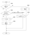
- FIG. 4 is a flow chart showing an example of data saving processing in a main memory and an auxiliary memory
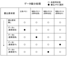
- FIG. 10 is a diagram showing the content of determining a write target based on the importance of data and the immediacy of writing to a memory in data distribution processing
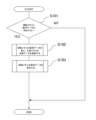
- 8 is a flowchart showing an example of data unification processing during shutdown processing and startup processing
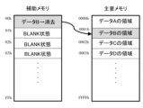
- It is a figure which shows the example of memory arrangement
- an in-vehicle control device 100 is a device that electronically controls in-vehicle equipment (eg, automatic transmission, engine, etc.) mounted on a vehicle.
- in-vehicle equipment eg, automatic transmission, engine, etc.
- the in-vehicle control device 100 includes a power supply circuit 110 connected to a battery 200, a CPU 140 (data control unit), an input/output circuit 120 connected to a sensor/actuator 210, and another in-vehicle control device 220 mounted in the same vehicle. It comprises a CAN circuit 130 that communicates with (other controllers), a main memory 150 that stores data according to instructions from a CPU 140, and an auxiliary memory 160.
- the CPU 140 can store the failure information in the main memory 150 and the auxiliary memory 160.
- the in-vehicle control device 100 may be configured to have a plurality of auxiliary memories 160, 160-2, 160-3, . . . 160-N).
- the data write process, data distribution process, and data save process in one embodiment of the present invention are processes performed by the CPU 140 when a data write request is issued to the main memory 150 and auxiliary memory 160 .
- step S001 the CPU 140 confirms whether the main memory 150 is being written or read. If the main memory 150 is not being written to and is not being read from, go to step S002.
- step S002 the CPU 140 requests the main memory 150 to write data.
- step S001 if the main memory 150 is being written or read, proceed to step S003.
- step S003 the CPU 140 confirms whether or not there is an auxiliary memory 160 that is neither being written nor read. If all the auxiliary memories 160 are being written or read, the process proceeds to step S004. In step S003, if there is an auxiliary memory 160 that is neither being written to nor read from, the process proceeds to step S005.
- step S004 the CPU 140 sets a write request in a queue that manages data write requests.
- the CPU 140 of the in-vehicle control device 100 uses communication means such as the CAN circuit 130 to transmit data to the other in-vehicle control device 220 (another control device), and the memory held by the other in-vehicle control device 220. It may be stored as an auxiliary memory. There are a plurality of memories used as auxiliary memories held by the other vehicle-mounted control devices 220, and they may be used separately for high immediacy memory, medium immediacy memory, and low immediacy memory. , a memory for high immediacy, a memory for medium immediacy, or a memory for low immediacy.
- step S005 the CPU 140 performs data distribution processing to determine the memory to be written based on the importance of the write request data and the usage status of each memory. Detailed processing of the data distribution processing will be described later with reference to FIG. 3 in [Data Distribution Processing].
- step S006 the CPU 140 issues a data write request to the auxiliary memory 160 determined in step S005 of the data allocation process.
- Data sorting process Data distribution processing will be described with reference to FIG. In FIG. 3, unused states are indicated by white circles, and memories selected for writing are indicated by black circles. Data A has a low degree of importance, and data B has a high degree of importance. Data C and data D have medium importance.
- Auxiliary memory 1, auxiliary memory 2, auxiliary memory 3, . . . auxiliary memory N (160, 160-2, 160-3, . . .
- auxiliary memory 1 (160) is for high immediacy
- auxiliary memory 2 (160-2) is for low immediacy
- auxiliary memory 3 (160-3) is for medium immediacy.
- the CPU 140 determines the memory to be written to based on the importance of data and the usage status of each memory in the order of write requests. As shown in FIG. 3, when a write request for data A is generated while no write request is generated, the main memory 150 is first selected as a write target.
- auxiliary memory 1 160 with high writing immediacy is selected.
- the memory to be written is determined by considering the importance of the write request data and the immediacy of writing to each memory.
- FIG. 4 is a flowchart showing an example of data unification processing during shutdown processing and startup processing of the in-vehicle control device 100 .
- Data unification processing is processing performed by the CPU 140 .
- Data management is facilitated by storing and subsequently reading only the main memory 150 .
- step S101 of FIG. 4 the CPU 140 checks whether data saved during normal control exists in the auxiliary memory (160, 160-2, . . . 160-N).
- auxiliary memory 160, 160-2, . . . 160-N
- step S102 the CPU 140 updates the data in the main memory 150 based on the data stored in the auxiliary memories (160, 160-2, . . . 160-N).
- step S103 the CPU 140 erases the data stored in the auxiliary memory (160, 160-2, . . . 160-N).
- the data unification process as described above can be executed, for example, during the shutdown process of the in-vehicle control device 100 . That is, by performing the data unification process during the shutdown process, the data saved in the auxiliary memory (160, 160-2, . , and centralized storage in the main memory 150, and reading out only the main memory 150 at the next start-up process, data management can be facilitated.
- the data unification process can be executed when the in-vehicle control device 100 is activated. For example, if the in-vehicle control device 100 is not properly shut down due to a momentary drop or momentary interruption of the battery 200 that supplies power, the above-described data unification process during the shutdown process will not be executed.
- 150 and the auxiliary memories 160, 160-2, . , 160-2, . . . 160-N), the data required for control can be read only from the main memory 150 thereafter. That is, this makes it possible to facilitate data management.
- FIG. 5 shows an example of memory allocation when data unification processing is performed.
- the CPU 140 performs data unification processing at the time of startup processing or shutdown processing, based on the data B stored in the auxiliary memories (160, 160-2, . . . 160-N), the main memory 150 update the data in the data B area of .
- the CPU 140 erases the data B in the auxiliary memory (160, 160-2, . . . 160-N) and performs control based on the data in the main memory 150.
- the in-vehicle controller 100 has a plurality of memory resources (main memory 150, auxiliary memories 160, 160-2, . )have.
- the CPU 140 which is the data control unit, performs data write processing and data storage processing when the main memory 150 is in use, and uses a plurality of auxiliary memories (160, 160-2, . . . 160-) as alternatives. N).
- main memory 150 main memory 150
- auxiliary memories 160, 160-2 auxiliary memories
- the CPU 140 which is a data control unit, determines the importance of the data requested to be written and the usage status of each memory (main memory 150, auxiliary memory (160, 160-2, . . . 160-N)). Since the memory to be written is determined and written, important failure information and driver's operation status at the time of accident occurrence can be read from the in-vehicle controller 100 by an external or internal in-vehicle diagnostic device. Therefore, it is possible to accurately grasp vehicle abnormality information and operating conditions, which contributes to the investigation of the cause of the accident.
- the CPU 140 stores data (updated data in the auxiliary memory) stored in the auxiliary memories (160, 160-2, . . . 150 is written into the data and integrated, all data necessary for control can be read out from the main memory 150 when the in-vehicle control device 1 is activated.
- the auxiliary memories 160, 160-2, . , a memory possessed by the in-vehicle control device 220, to which written data can be notified by communication means or the like.
- the vehicle-mounted control device also includes a drive recorder that stores the ever-changing status of the vehicle and the external situation of the vehicle.
- the present invention even in a drive recorder as an in-vehicle control device, even when a plurality of data write requests are generated from a plurality of cameras at the same time, there is no need to wait for data writing. It is possible to minimize the risk that important data cannot be written and lost due to a momentary voltage drop or interruption of the power supply while it is in use.
- SYMBOLS 100... Vehicle-mounted control apparatus, 110... Power supply circuit, 120... Input-output circuit, 130... CAN circuit, 140... CPU (data control part), 150... Main memory, 160, 160-2, 160-3, 160-N...Auxiliary memory, 200...Battery, 210...Sensor/actuator, 220...Other in-vehicle controllers
Landscapes
- Engineering & Computer Science (AREA)
- Mechanical Engineering (AREA)
- Techniques For Improving Reliability Of Storages (AREA)
Abstract
複数のデータの書込要求が同時に発生した場合に、電源瞬低・瞬断等で、重要なデータの書込が出来ず、消失するリスクを低減可能な車載制御装置(100)が実現される。車載制御装置(100)は、データを記憶する主要メモリ(150)と、データを記憶する複数の補助メモリ(160、160-2、160-3、・・・160-N)と、主要メモリ(150)及び複数の補助メモリ(160、160-2、160-3、・・・160-N)へのデータ書込処理、データ振分処理及びデータ保存処理を行うデータ制御部であるCPU(140)と、を備える。CPU(140)は、データ書込処理及びデータ保存処理を、主要メモリ(150)が使用中の場合、代替として複数の補助メモリ(160、160-2、160-3、・・・160-N)のいずれかに対して実行する。
Description
本発明は、車載制御装置のメモリ保存方式に関する。
車載制御装置において、車両走行中に発生した故障情報や学習情報等で保持する必要がある重要なデータは不揮発性メモリに保存する。
近年、車載制御装置の高機能化や、交通事故の原因究明のため、車両のアクセルやブレーキなどの操作状況を自動記録するデータレコーダー機能の搭載が義務化されることから、記憶するデータが増加し、重要度の高いデータなどは、走行中に即座に不揮発性メモリに書込が必要なケースが増加している。
特許文献1に記載の車載制御装置は、車両走行中に、定期的に所定のデータを1つの不揮発性メモリに対し、書き込むことで、イグニッションオフ後も必要なデータを保持する手法が取られている。
特許文献1に記載の技術では、上述したとおり、車両走行中に記憶するデータが増加し、書込要求が重なった場合、1つの不揮発メモリに対し、順次書き込む調停が行われるが、調停により待たされている間に、車載制御装置に供給する電源の瞬低・瞬断等により、重要データの書込ができないリスクが増加する課題がある。
本発明の目的は、複数のデータの書込要求が同時に発生した場合に、電源瞬低・瞬断等で、重要なデータの書込が出来ず、消失するリスクを低減可能な車載制御装置を実現することである。
上記目的を達成するため、本発明は次の様に構成される。
車載制御装置において、データを記憶する主要メモリと、データを記憶する複数の補助メモリと、前記主要メモリ及び前記複数の補助メモリへのデータ書込処理、データ振分処理及びデータ保存処理を行うデータ制御部と、を備え、前記データ制御部は、前記データ書込処理及び前記データ保存処理を、前記主要メモリが使用中の場合、代替として前記複数の補助メモリのいずれかに対して実行する。
本発明によれば、複数のデータの書込要求が同時に発生した場合に、電源瞬低・瞬断等で、重要なデータの書込が出来ず、消失するリスクを低減可能な車載制御装置を実現することができる。
以下、本発明を実施するための形態の例について、添付図面を参照して説明する。
[全体構成]
まず、図1を用いて、本発明の一実施例に係る車載制御装置100の概略構成について説明する。
まず、図1を用いて、本発明の一実施例に係る車載制御装置100の概略構成について説明する。
図1において、車載制御装置100は、車両が搭載する車載機器(例えば自動変速機、エンジンなど)を電子的に制御する装置である。
車載制御装置100は、バッテリ200と接続する電源回路110と、CPU140(データ制御部)と、センサ・アクチュエータ210と接続する入出力回路120と、同一の車両に搭載された他の車載制御装置220(他の制御装置)と通信を行うCAN回路130と、CPU140からの指示によりデータを保存する主要メモリ150と、補助メモリ160と、を備えている。
CPU140は、センサ・アクチュエータ210の故障が発生した場合、故障情報を主要メモリ150や補助メモリ160に保存することができる。
また、車載制御装置100は、図1に示すように、複数の補助メモリ160、160-2、160-3、・・・160-N)を持つ構成でもよい。
[主要メモリ及び補助メモリへのデータ保存処理]
図2のフローチャートを用いて、主要メモリ150及び補助メモリ160へのデータ保存処理を説明する。
図2のフローチャートを用いて、主要メモリ150及び補助メモリ160へのデータ保存処理を説明する。
本発明の一実施例におけるデータ書込処理、データ振分処理及びデータ保存処理は、主要メモリ150及び補助メモリ160に対し、データの書込要求が発生した場合にCPU140によって行われる処理である。
ステップS001において、CPU140は、主要メモリ150が書込中、もしくは読出中の状態であるかを確認する。主要メモリ150が書込中ではない場合、かつ、読出中ではない場合は、ステップS002に進む。
ステップS002において、CPU140は、主要メモリ150にデータの書込要求を行う。
ステップS001において、主要メモリ150が書込中、もしくは、読出中の場合、ステップS003に進む。
ステップS003において、CPU140は、書込中ではなく、かつ、読出中ではない補助メモリ160が存在するか否かを確認する。全ての補助メモリ160が書込中もしくは読出中の場合、ステップS004に進む。ステップS003において、書込中ではなく、かつ、読出中ではない補助メモリ160が存在する場合、ステップS005に進む。
ステップS004において、CPU140は、データの書込要求を管理するキューに書込要求をセットする。もしくは、車載制御装置100のCPU140は、CAN回路130等の通信手段を利用し、他の車載制御装置220(他の制御装置)にデータを送信し、他の車載制御装置220の保有するメモリを補助メモリとし保存するのでも良い。他の車載制御装置220が保有する補助メモリとして使用するメモリは、複数であり、即時性高用のメモリ、即時性中用のメモリ及び即時性低用のメモリに区別して使用してもよいし、即時性高用のメモリ、即時性中用のメモリ又は即時性低用のメモリのいずれか一つ(若しくは二つ)として使用してもよい。
ステップS005において、CPU140は、書込要求データの重要度、各メモリの使用状況から、書込対象のメモリを決定する、データ振分処理を行う。データ振分処理の詳細処理は、後述する[データ振分処理]において、図3を用いて説明する。
ステップS006において、CPU140は、データ振分処理のステップS005で決定した補助メモリ160に対し、データの書込要求を出す。
[データ振分処理]
図3を用いて、データ振分処理を説明する。図3において、未使用状態を白丸で示し、書込みが選択されたメモリを黒丸で示す。また、データAは重要度が低であり、データBは重要度が高である。そして、データC及びデータDは重要度が中である。
図3を用いて、データ振分処理を説明する。図3において、未使用状態を白丸で示し、書込みが選択されたメモリを黒丸で示す。また、データAは重要度が低であり、データBは重要度が高である。そして、データC及びデータDは重要度が中である。
また、補助メモリ1、補助メモリ2、補助メモリ3、・・・補助メモリN(160、160-2、160-3、・・・160-N)は、即時性高用のメモリ、即時性中用のメモリ及び即時性低用のメモリに区別されている。図3に示した例では、補助メモリ1(160)が即時性高用のメモリ、補助メモリ2(160-2)が即時性低用のメモリ、補助メモリ3(160-3)が即時性中用のメモリである。
CPU140は、書込要求順に、データの重要度及び、各メモリの使用状況から、書込対象のメモリを決定する。図3に示すように、書込要求が発生していない状態で、データAの書込要求が発生した場合、まず主要メモリ150を書込対象として選択する。
次に、データBの書込要求が発生した場合、主要メモリ150が書込中のため、補助メモリ160、160-2、160-3、・・・160-N)から選択し、書込が要求されたデータの重要度が高いほど、書込の即時性が高いメモリを選択してデータ書込処理を行う。データBの重要度が高いことから、書込の即時性が高い補助メモリ1(160)を選択する。
同様に、データC及びデータDに関しても、書込要求データの重要度と各メモリの書込即時性を考慮し、書込対象のメモリを決定する。
このように、書込要求データの重要度か高いほど、書込の即時性が高いメモリを選択することで、重要なデータが書込できず、消失するリスクを更に低減することが可能である。
[データ一元化処理]
図4は、車載制御装置100のシャットダウン処理時及び起動処理時における、データ一元化処理の一例を示すフローチャートである。データ一元化処理は、CPU140によって行われる処理である。
図4は、車載制御装置100のシャットダウン処理時及び起動処理時における、データ一元化処理の一例を示すフローチャートである。データ一元化処理は、CPU140によって行われる処理である。
データ一元化処理は、通常制御中に複数のデータの書込要求が重なったことから補助メモリ(160、160-2、・・・160-N)に保存したデータを、主要メモリ150に一元化して格納し、以降は主要メモリ150のみを読み出すことで、データの管理を容易化する。
図4のステップS101において、CPU140は、補助メモリ(160、160-2、・・・160-N)に、通常制御中に保存されたデータが存在するか確認する。
補助メモリ(160、160-2、・・・160-N)に保存されたデータが存在する場合、ステップS102に進む。補助メモリ(160、160-2、・・・160-N)に保存されたデータが存在しない場合、処理終了とする。
ステップS102において、CPU140は、補助メモリ(160、160-2、・・・160-N)の保存データを基に、主要メモリ150のデータを更新する。
ステップS103において、CPU140は、補助メモリ(160、160-2、・・・160-N)の保存データを消去する。
このように、補助メモリ(160、160-2、・・・160-N)の保存データを主要メモリ150のデータに一元化し、以降、CPU140は、主要メモリ150のみから制御に必要なデータを読み出すようにすることで、データの管理を容易化することができる。
上述したようなデータ一元化処理は、たとえば、車載制御装置100のシャットダウン処理時に実行することができる。すなわち、シャットダウン処理時にデータ一元化処理を行うことで、通常制御中に複数のデータの書込要求が重なったことから補助メモリ(160、160-2、・・・160-N)に保存したデータを、主要メモリ150に一元化して格納し、次回起動処理時には主要メモリ150のみを読み出すようにすることで、データの管理を容易化することができる。
また、データ一元化処理は、車載制御装置100の起動処理時に実行することができる。たとえば、電源を供給するバッテリ200の瞬低・瞬断により、車載制御装置100が正常にシャットダウン処理されていない場合は、上述のシャットダウン処理時のデータ一元化処理が実行されない状態となるため、主要メモリ150と補助メモリ(160、160-2、・・・160-N)にデータが分散保存されている状態が発生し得るが、このような場合、車載制御装置100の起動処理時に補助メモリ(160、160-2、・・・160-N)のデータを基に主要メモリ150を更新することで、以降は主要メモリ150のみから制御に必要なデータを読み出すことが可能となる。すなわち、これによって、データの管理を容易化することができる。
[データ一元化処理によるメモリ配置]
図5に、データ一元化処理を行った際のメモリ配置の例を示す。
図5に、データ一元化処理を行った際のメモリ配置の例を示す。
図5において、CPU140は、起動処理時もしくはシャットダウン処理時のデータ一元化処理により、補助メモリ(160、160-2、・・・160-N)に保存されているデータBを基に、主要メモリ150のデータBの領域のデータを更新する。
その後、CPU140は、補助メモリ(160、160-2、・・・160-N)のデータBを消去し、主要メモリ150のデータを基に制御を行う。
本発明の一実施例による車載制御装置100は、車両の走行等に関するデータの書込先の対象として、複数のメモリ資源(主要メモリ150、補助メモリ160、160-2、・・・160-N)を持つ。
本発明においては、データ制御部であるCPU140は、データ書込処理及びデータ保存処理を、主要メモリ150が使用中の場合、代替として複数の補助メモリ(160、160-2、・・・160-N)のいずれかに対して実行する。
よって、上述したように、複数のメモリ資源(主要メモリ150、補助メモリ160、160-2、・・・160-N)を持つことにより、複数のデータの書込要求が同時に発生した場合、待たされるケースが無くなり、待たされている間に電源瞬低・瞬断等で、重要なデータの書込が出来ず、消失するリスクを限りなく低減することができる。
これにより、従来技術においては、電源の瞬低・瞬断により消失していた重要な学習値を保持可能となり車両の運転性や安全性を向上することができる。
また、データ制御部であるCPU140は、書込が要求されたデータの重要度、各メモリ(主要メモリ150、補助メモリ(160、160-2、・・・160-N))の使用状況から、書込対象メモリを決定し、書込を行うように構成されているので、重要な故障情報や事故発生時の運転者の操作状況を車載制御装置100から外部または内部の車載診断機で読み出すことが可能であることから、車両の異常情報や操作状況を正確に把握することが向上され、事故原因の究明に寄与することができる。
加えて、書込要求データの重要度が高いほど、書込の即時性が高いメモリを選択することで、重要なデータが書込できず、消失するリスクを更に低減することが可能である。
また、車載制御装置1のシャットダウン処理時及び起動処理時に、CPU140が補助メモリ(160、160-2、・・・160-N)に記憶されたデータ(補助メモリの更新されたデータ)を主要メモリ150のデータに書き込み、一元化するので、車載制御装置1の起動処理時に、主要メモリ150から制御に必要なデータを、残すこと無く読み出すことができる。
なお、主要メモリ150が使用中の場合、代替としてデータ書込処理及びデータ保存処理を行う補助メモリ(160、160-2、・・・160-N)は、車載制御装置100自身のメモリではなく、通信手段等で書込データを通知可能な他車載制御装置220の保有するメモリでも可能である。
また、本発明において、車載制御装置とは、時々刻々と変化する自車両のステータスや自車両の外部状況を記憶するドライブレコーダも含まれる。
本発明によれば、車載制御装置としてのドライブレコーダにおいても、複数のカメラから、複数のデータの書込要求が同時に発生した場合等であっても、データ書き込みが待たされるケースが無くなり、待たされている間に電源瞬低・瞬断等で、重要なデータの書込が出来ず、消失するリスクを限りなく低減することができる。
100・・・車載制御装置、110・・・電源回路、120・・・入出力回路、130・・・CAN回路、140・・・CPU(データ制御部)、150・・・主要メモリ、160、160-2、160-3、160-N・・・補助メモリ、200・・・バッテリ、210・・・センサ・アクチュエータ、220・・・他の車載制御装置
Claims (6)
- データを記憶する主要メモリと、
データを記憶する複数の補助メモリと、
前記主要メモリ及び前記複数の補助メモリへのデータ書込処理、データ振分処理及びデータ保存処理を行うデータ制御部と、
を備え、前記データ制御部は、前記データ書込処理及び前記データ保存処理を、前記主要メモリが使用中の場合、代替として前記複数の補助メモリのいずれかに対して実行することを特徴とする車載制御装置。 - 請求項1に記載の車載制御装置において、
前記データ制御部は、書込が要求されたデータの重要度、各メモリの使用状況から、書込対象メモリを決定し、書込を行うことを特徴とする車載制御装置。 - 請求項1に記載の車載制御装置において、
前記複数の補助メモリは、即時性高用のメモリ、即時性中用のメモリ及び即時性低用のメモリに区別され、
前記データ制御部は、前記複数の補助メモリのうち、書込が要求されたデータの重要度が高いほど、書込の即時性が高いメモリを選択して前記データ書込処理を行うことを特徴とする車載制御装置。 - 請求項1に記載の車載制御装置において、
前記データ制御部は、前記複数の補助メモリの更新されたデータを、車載制御装置のシャットダウン処理時に、全てのデータを一括して管理する前記主要メモリに書込み、データの一元化を行うことを特徴とする車載制御装置。 - 請求項4に記載の車載制御装置において、
前記データ制御部は、前記複数の補助メモリの更新されたデータを、車載制御装置のシャットダウン処理時及び起動処理時に、全てのデータを一括して管理する前記主要メモリに書込み、データの一元化を行うことを特徴とする車載制御装置。 - 請求項1に記載の車載制御装置において、
前記データ制御部は、前記主要メモリが使用中の場合、他の車載制御装置の保有するメモリを前記補助メモリの代替としてデータの書込処理及び前記データ保存処理を行うことを特徴とする車載制御装置。
Priority Applications (2)
| Application Number | Priority Date | Filing Date | Title |
|---|---|---|---|
| JP2023568848A JP7660715B6 (ja) | 2021-12-21 | 2021-12-21 | 車載制御装置 |
| PCT/JP2021/047412 WO2023119448A1 (ja) | 2021-12-21 | 2021-12-21 | 車載制御装置 |
Applications Claiming Priority (1)
| Application Number | Priority Date | Filing Date | Title |
|---|---|---|---|
| PCT/JP2021/047412 WO2023119448A1 (ja) | 2021-12-21 | 2021-12-21 | 車載制御装置 |
Publications (1)
| Publication Number | Publication Date |
|---|---|
| WO2023119448A1 true WO2023119448A1 (ja) | 2023-06-29 |
Family
ID=86901677
Family Applications (1)
| Application Number | Title | Priority Date | Filing Date |
|---|---|---|---|
| PCT/JP2021/047412 Ceased WO2023119448A1 (ja) | 2021-12-21 | 2021-12-21 | 車載制御装置 |
Country Status (2)
| Country | Link |
|---|---|
| JP (1) | JP7660715B6 (ja) |
| WO (1) | WO2023119448A1 (ja) |
Citations (5)
| Publication number | Priority date | Publication date | Assignee | Title |
|---|---|---|---|---|
| JPH06259337A (ja) * | 1993-03-09 | 1994-09-16 | Hitachi Ltd | データ保護方式 |
| JP2012048390A (ja) * | 2010-08-25 | 2012-03-08 | Auto Network Gijutsu Kenkyusho:Kk | 制御システム、制御装置、制御方法及びコンピュータプログラム |
| JP2013161242A (ja) * | 2012-02-03 | 2013-08-19 | Toyota Motor Corp | 電子制御装置 |
| JP2015116945A (ja) * | 2013-12-19 | 2015-06-25 | 日立オートモティブシステムズ株式会社 | 車載制御装置および車載制御システム |
| JP2017043354A (ja) * | 2016-09-05 | 2017-03-02 | 日立オートモティブシステムズ株式会社 | 自動車用電子制御装置 |
-
2021
- 2021-12-21 JP JP2023568848A patent/JP7660715B6/ja active Active
- 2021-12-21 WO PCT/JP2021/047412 patent/WO2023119448A1/ja not_active Ceased
Patent Citations (5)
| Publication number | Priority date | Publication date | Assignee | Title |
|---|---|---|---|---|
| JPH06259337A (ja) * | 1993-03-09 | 1994-09-16 | Hitachi Ltd | データ保護方式 |
| JP2012048390A (ja) * | 2010-08-25 | 2012-03-08 | Auto Network Gijutsu Kenkyusho:Kk | 制御システム、制御装置、制御方法及びコンピュータプログラム |
| JP2013161242A (ja) * | 2012-02-03 | 2013-08-19 | Toyota Motor Corp | 電子制御装置 |
| JP2015116945A (ja) * | 2013-12-19 | 2015-06-25 | 日立オートモティブシステムズ株式会社 | 車載制御装置および車載制御システム |
| JP2017043354A (ja) * | 2016-09-05 | 2017-03-02 | 日立オートモティブシステムズ株式会社 | 自動車用電子制御装置 |
Also Published As
| Publication number | Publication date |
|---|---|
| JP7660715B2 (ja) | 2025-04-11 |
| JP7660715B6 (ja) | 2025-05-22 |
| JPWO2023119448A1 (ja) | 2023-06-29 |
Similar Documents
| Publication | Publication Date | Title |
|---|---|---|
| CN113535081B (zh) | 数据存储装置的装置维护 | |
| JP5262936B2 (ja) | 車両制御装置 | |
| US11340887B2 (en) | Method for performing a software update in a control unit of a motor vehicle, and motor vehicle designed accordingly | |
| JP5138760B2 (ja) | 情報記録装置 | |
| WO2018079008A1 (ja) | 制御装置、プログラム更新方法、およびコンピュータプログラム | |
| JP2007504987A (ja) | エネルギー管理方法 | |
| KR102109125B1 (ko) | Autosar 기반 차량 ecu 상태 관리 방법 | |
| WO2024023873A1 (ja) | 車載制御装置 | |
| CN116653900A (zh) | 基于车辆冗余制动系统的车辆控制方法、装置和设备 | |
| CN118215906A (zh) | 遇险模式下易失性数据的保存 | |
| JP7660715B2 (ja) | 車載制御装置 | |
| WO2020162430A1 (ja) | 電子制御装置及び不揮発性メモリの使用方法 | |
| JP2025168511A (ja) | 更新管理システム | |
| JP5182583B2 (ja) | 車両用通信制御装置 | |
| JP3296043B2 (ja) | 車両用電子制御装置 | |
| JP5034866B2 (ja) | 車載制御装置 | |
| US20240160489A1 (en) | Method for Allocating Resources of a Vehicle, Method for Generating a Graph for a Vehicle, and Computer-Readable Storage Medium | |
| JP7836703B2 (ja) | 車両制御システム、及び、プログラム書込方法 | |
| WO2019044226A1 (ja) | アクセス制御装置 | |
| JP2014154024A (ja) | 車両制御データ記憶装置 | |
| JP3750692B2 (ja) | 車両用電子制御装置 | |
| US20260062011A1 (en) | Vehicle control system | |
| WO2025263197A1 (ja) | 電子制御装置、メモリの活用方法及びメモリの活用プログラム | |
| JP4734096B2 (ja) | エレベーター用制御システム | |
| CN121680875A (zh) | 数据刷写方法、装置、电子设备、车辆及存储介质 |
Legal Events
| Date | Code | Title | Description |
|---|---|---|---|
| 121 | Ep: the epo has been informed by wipo that ep was designated in this application |
Ref document number: 21968885 Country of ref document: EP Kind code of ref document: A1 |
|
| ENP | Entry into the national phase |
Ref document number: 2023568848 Country of ref document: JP Kind code of ref document: A |
|
| NENP | Non-entry into the national phase |
Ref country code: DE |
|
| 122 | Ep: pct application non-entry in european phase |
Ref document number: 21968885 Country of ref document: EP Kind code of ref document: A1 |