WO2023119407A1 - 駆動操舵制御システム、組込式駆動操舵ユニットシステム、組込式駆動操舵ユニット及び自動運転地上車両 - Google Patents
駆動操舵制御システム、組込式駆動操舵ユニットシステム、組込式駆動操舵ユニット及び自動運転地上車両 Download PDFInfo
- Publication number
- WO2023119407A1 WO2023119407A1 PCT/JP2021/047269 JP2021047269W WO2023119407A1 WO 2023119407 A1 WO2023119407 A1 WO 2023119407A1 JP 2021047269 W JP2021047269 W JP 2021047269W WO 2023119407 A1 WO2023119407 A1 WO 2023119407A1
- Authority
- WO
- WIPO (PCT)
- Prior art keywords
- steering
- motor
- drive
- propulsion
- instruction information
- Prior art date
- Legal status (The legal status is an assumption and is not a legal conclusion. Google has not performed a legal analysis and makes no representation as to the accuracy of the status listed.)
- Ceased
Links
Images



Classifications
-
- B—PERFORMING OPERATIONS; TRANSPORTING
- B60—VEHICLES IN GENERAL
- B60W—CONJOINT CONTROL OF VEHICLE SUB-UNITS OF DIFFERENT TYPE OR DIFFERENT FUNCTION; CONTROL SYSTEMS SPECIALLY ADAPTED FOR HYBRID VEHICLES; ROAD VEHICLE DRIVE CONTROL SYSTEMS FOR PURPOSES NOT RELATED TO THE CONTROL OF A PARTICULAR SUB-UNIT
- B60W10/00—Conjoint control of vehicle sub-units of different type or different function
- B60W10/20—Conjoint control of vehicle sub-units of different type or different function including control of steering systems
-
- B—PERFORMING OPERATIONS; TRANSPORTING
- B62—LAND VEHICLES FOR TRAVELLING OTHERWISE THAN ON RAILS
- B62D—MOTOR VEHICLES; TRAILERS
- B62D6/00—Arrangements for automatically controlling steering depending on driving conditions sensed and responded to, e.g. control circuits
- B62D6/002—Arrangements for automatically controlling steering depending on driving conditions sensed and responded to, e.g. control circuits computing target steering angles for front or rear wheels
-
- B—PERFORMING OPERATIONS; TRANSPORTING
- B60—VEHICLES IN GENERAL
- B60L—PROPULSION OF ELECTRICALLY-PROPELLED VEHICLES; SUPPLYING ELECTRIC POWER FOR AUXILIARY EQUIPMENT OF ELECTRICALLY-PROPELLED VEHICLES; ELECTRODYNAMIC BRAKE SYSTEMS FOR VEHICLES IN GENERAL; MAGNETIC SUSPENSION OR LEVITATION FOR VEHICLES; MONITORING OPERATING VARIABLES OF ELECTRICALLY-PROPELLED VEHICLES; ELECTRIC SAFETY DEVICES FOR ELECTRICALLY-PROPELLED VEHICLES
- B60L15/00—Methods, circuits, or devices for controlling the traction-motor speed of electrically-propelled vehicles
- B60L15/20—Methods, circuits, or devices for controlling the traction-motor speed of electrically-propelled vehicles for control of the vehicle or its driving motor to achieve a desired performance, e.g. speed, torque, programmed variation of speed
-
- B—PERFORMING OPERATIONS; TRANSPORTING
- B60—VEHICLES IN GENERAL
- B60W—CONJOINT CONTROL OF VEHICLE SUB-UNITS OF DIFFERENT TYPE OR DIFFERENT FUNCTION; CONTROL SYSTEMS SPECIALLY ADAPTED FOR HYBRID VEHICLES; ROAD VEHICLE DRIVE CONTROL SYSTEMS FOR PURPOSES NOT RELATED TO THE CONTROL OF A PARTICULAR SUB-UNIT
- B60W10/00—Conjoint control of vehicle sub-units of different type or different function
- B60W10/04—Conjoint control of vehicle sub-units of different type or different function including control of propulsion units
- B60W10/08—Conjoint control of vehicle sub-units of different type or different function including control of propulsion units including control of electric propulsion units, e.g. motors or generators
-
- B—PERFORMING OPERATIONS; TRANSPORTING
- B60—VEHICLES IN GENERAL
- B60W—CONJOINT CONTROL OF VEHICLE SUB-UNITS OF DIFFERENT TYPE OR DIFFERENT FUNCTION; CONTROL SYSTEMS SPECIALLY ADAPTED FOR HYBRID VEHICLES; ROAD VEHICLE DRIVE CONTROL SYSTEMS FOR PURPOSES NOT RELATED TO THE CONTROL OF A PARTICULAR SUB-UNIT
- B60W10/00—Conjoint control of vehicle sub-units of different type or different function
- B60W10/18—Conjoint control of vehicle sub-units of different type or different function including control of braking systems
-
- B—PERFORMING OPERATIONS; TRANSPORTING
- B60—VEHICLES IN GENERAL
- B60W—CONJOINT CONTROL OF VEHICLE SUB-UNITS OF DIFFERENT TYPE OR DIFFERENT FUNCTION; CONTROL SYSTEMS SPECIALLY ADAPTED FOR HYBRID VEHICLES; ROAD VEHICLE DRIVE CONTROL SYSTEMS FOR PURPOSES NOT RELATED TO THE CONTROL OF A PARTICULAR SUB-UNIT
- B60W30/00—Purposes of road vehicle drive control systems not related to the control of a particular sub-unit, e.g. of systems using conjoint control of vehicle sub-units
- B60W30/02—Control of vehicle driving stability
- B60W30/045—Improving turning performance
-
- B—PERFORMING OPERATIONS; TRANSPORTING
- B60—VEHICLES IN GENERAL
- B60W—CONJOINT CONTROL OF VEHICLE SUB-UNITS OF DIFFERENT TYPE OR DIFFERENT FUNCTION; CONTROL SYSTEMS SPECIALLY ADAPTED FOR HYBRID VEHICLES; ROAD VEHICLE DRIVE CONTROL SYSTEMS FOR PURPOSES NOT RELATED TO THE CONTROL OF A PARTICULAR SUB-UNIT
- B60W60/00—Drive control systems specially adapted for autonomous road vehicles
- B60W60/001—Planning or execution of driving tasks
-
- B—PERFORMING OPERATIONS; TRANSPORTING
- B62—LAND VEHICLES FOR TRAVELLING OTHERWISE THAN ON RAILS
- B62D—MOTOR VEHICLES; TRAILERS
- B62D5/00—Power-assisted or power-driven steering
- B62D5/04—Power-assisted or power-driven steering electrical, e.g. using an electric servo-motor connected to, or forming part of, the steering gear
- B62D5/0418—Electric motor acting on road wheel carriers
-
- B—PERFORMING OPERATIONS; TRANSPORTING
- B60—VEHICLES IN GENERAL
- B60W—CONJOINT CONTROL OF VEHICLE SUB-UNITS OF DIFFERENT TYPE OR DIFFERENT FUNCTION; CONTROL SYSTEMS SPECIALLY ADAPTED FOR HYBRID VEHICLES; ROAD VEHICLE DRIVE CONTROL SYSTEMS FOR PURPOSES NOT RELATED TO THE CONTROL OF A PARTICULAR SUB-UNIT
- B60W2520/00—Input parameters relating to overall vehicle dynamics
- B60W2520/28—Wheel speed
-
- B—PERFORMING OPERATIONS; TRANSPORTING
- B60—VEHICLES IN GENERAL
- B60W—CONJOINT CONTROL OF VEHICLE SUB-UNITS OF DIFFERENT TYPE OR DIFFERENT FUNCTION; CONTROL SYSTEMS SPECIALLY ADAPTED FOR HYBRID VEHICLES; ROAD VEHICLE DRIVE CONTROL SYSTEMS FOR PURPOSES NOT RELATED TO THE CONTROL OF A PARTICULAR SUB-UNIT
- B60W2540/00—Input parameters relating to occupants
- B60W2540/18—Steering angle
-
- B—PERFORMING OPERATIONS; TRANSPORTING
- B60—VEHICLES IN GENERAL
- B60W—CONJOINT CONTROL OF VEHICLE SUB-UNITS OF DIFFERENT TYPE OR DIFFERENT FUNCTION; CONTROL SYSTEMS SPECIALLY ADAPTED FOR HYBRID VEHICLES; ROAD VEHICLE DRIVE CONTROL SYSTEMS FOR PURPOSES NOT RELATED TO THE CONTROL OF A PARTICULAR SUB-UNIT
- B60W2710/00—Output or target parameters relating to a particular sub-units
- B60W2710/08—Electric propulsion units
- B60W2710/083—Torque
-
- B—PERFORMING OPERATIONS; TRANSPORTING
- B60—VEHICLES IN GENERAL
- B60W—CONJOINT CONTROL OF VEHICLE SUB-UNITS OF DIFFERENT TYPE OR DIFFERENT FUNCTION; CONTROL SYSTEMS SPECIALLY ADAPTED FOR HYBRID VEHICLES; ROAD VEHICLE DRIVE CONTROL SYSTEMS FOR PURPOSES NOT RELATED TO THE CONTROL OF A PARTICULAR SUB-UNIT
- B60W2710/00—Output or target parameters relating to a particular sub-units
- B60W2710/20—Steering systems
- B60W2710/202—Steering torque
Definitions
- the present invention relates to a drive steering control system, an embedded drive steering unit system, an embedded drive steering unit and an autonomous ground vehicle.
- Self-driving ground vehicles are known as vehicles that can run without a human driver.
- Self-driving ground vehicles for example, comprise a plurality of wheels and propulsion and steering motors associated with each of the wheels.
- the propulsion motors for example, transmit power to the wheels so that the self-driving ground vehicle can move forward and backward.
- the steering motors for example, transmit power to the wheels so that the self-driving ground vehicle can turn left and right.
- Such self-driving ground vehicles are disclosed, for example, in US Pat.
- Patent Literature 1 discloses a self-propelled lawn mower having three wheels and propulsion motors and steering motors provided for each of the three wheels.
- each of the three wheels is independently steered by a steering motor and rotated about an axle by a propulsion motor.
- a propulsion motor and a steering motor are attached to the body of the self-propelled lawn mower.
- the propulsion motor and steering motor are connected to the wheels via a steering shaft.
- the steering shaft is arranged to have a scrub radius with respect to the wheels.
- Patent Document 2 discloses an omnidirectional vehicle that includes caster-shaped wheels, a propulsion motor that rotates the wheels, and a steering motor that steers the wheels. Also in this omnidirectional vehicle, the steering axis is arranged with a scrub radius in relation to the wheels.
- An object of the present invention is to suppress both speed interference and torque interference between a steering motor and a drive motor in an autonomous driving ground vehicle having a scrub radius.
- the propulsion motor In a vehicle with a scrub radius, assume that one of the wheels is steered while the vehicle is stationary. In order to stop the vehicle at this time, the propulsion motor is instructed to keep the number of revolutions at zero, and the steering motor is instructed to rotate by a predetermined amount. As a result, the propulsion motor does not rotate, and only the steering motor rotates. Since the wheels have a scrub radius, they are not steered on the spot, but are steered so as to draw an arc-shaped trajectory centered on the steering axis and having a radius equal to the scrub radius. In this case, the wheels must rotate about their axles by the length of the trajectory.
- the propulsion motor since the propulsion motor has been instructed to stop, it will try to counteract the motion of the wheels being steered. In other words, the propulsion motor acts to impede the steering of the wheels, resulting in speed interference with the steering motor. As a result, the steering motor needs to output a torque larger than the originally required torque in order to steer the wheels smoothly, which may lead to a decrease in energy efficiency. In addition, a steering motor with a large output torque may be required, and as the amount of heat generated by the steering motor increases, it may be necessary to take countermeasures against heat generation. As a result, the size of the steering motor may increase. Additionally, the wheels can scrape the ground if they are steered without rotating about their axles. For example, in agricultural fields, golf courses, etc., it is desirable that the friction between wheels and the ground be small.
- the rotation speed of the wheels is corrected based on the scrub radius.
- the scrub radius is set in consideration of speed interference between the propulsion motor and the steering motor when the wheels are steered while the vehicle is stopped. As a result, in the vehicles of Patent Documents 1 and 2, speed interference between the propulsion motor and the steering motor is suppressed.
- the inventor studied an autonomous driving ground vehicle with a scrub radius. As a result, it was found that in an autonomous driving ground vehicle in which a plurality of wheels are independently steered and driven, mutual interference between the propulsion motor and the steering motor may occur in addition to the speed interference described above.
- the vehicle accelerates straight forward without steering the wheels.
- the vehicle instructs the propulsion motor to output a predetermined rotation speed or torque, and instructs the steering motor to keep the steering angle of the wheels at zero.
- the steering motor does not rotate, and only the propulsion motor rotates.
- the steering shaft experiences a moment due to the product of the scrub radius and the wheel drive force. This moment becomes a disturbance moment for the steering control system, and the steering angle changes from the target value.
- the steering motor has received an instruction to stop.
- the steering shaft receives the above-described disturbance moment and the wheels tend to be steered, resulting in torque interference between the steering motor and the propulsion motor.
- the steering angle of the wheels changes from the target value due to torque interference
- the toe angle changes from the target value
- the rolling resistance of the wheels also changes.
- An increase in rolling resistance increases the load on the propulsion motor and reduces fuel consumption.
- the resistance that a vehicle receives includes slope resistance, air resistance, acceleration resistance, etc.
- Self-driving ground vehicles often travel at low speeds on level ground.
- Rolling resistance accounts for a large proportion of the various types of resistance that autonomous driving ground vehicles receive compared to other vehicles. Therefore, it is desirable that the change from the target value of the steering angle due to torque interference be small.
- the steering angle of the wheels has changed from the desired value while the vehicle is accelerating straight ahead.
- the vehicle is equipped with a steering angle sensor.
- a steering angle sensor detects the amount of change in the steering angle of the wheels.
- the steering angle sensor transmits the amount of change in the detected steering angle to the controller for the steering motor. Based on the received amount of change in the steering angle, the control device operates the stopped steering motor to steer the wheels.
- the steering angle of the wheels can be returned to the target value by operating the steering motor.
- the feedback control is reactive, the steering angle of the wheels differs from the target value during the transient period from when the steering shaft receives the above-mentioned disturbance moment until the steering angle of the target wheel converges to the target value. end up
- the inventor further studied speed interference and torque interference between the propulsion motor and the steering motor. As a result, it has been found that speed and torque interference between the propulsion motor and the steering motor occur other than when the wheels are steered while the vehicle is stationary and when the vehicle accelerates straight ahead without steering the wheels.
- the vehicle activates the propulsion motor and also activates the steering motor.
- the propulsion motors operate, the torque interference described above occurs.
- the steering motor operates, the speed interference described above occurs. That is, it has been found that both speed interference and torque interference occur between the propulsion motor and the steering motor when the vehicle turns.
- the inventor of the present invention has studied a technique for suppressing speed interference and torque interference in all cases where speed interference and torque interference between a propulsion motor and a steering motor occur independently, and where both speed interference and torque interference occur. bottom. As a result, the inventor of the present invention came up with the following configuration.
- a drive steering control system is used in an autonomous ground vehicle that can run without a driver on board and has multiple wheels.
- the autonomous driving ground vehicle is connected to a target wheel that is one of a plurality of wheels, a propulsion motor that rotates the target wheel around the axle of the target wheel, a steering motor that steers the target wheel left and right, and a steering motor. and a steering shaft arranged to have a scrub radius with respect to the target wheel, configured to steer the target wheel left and right when the steering motor is actuated.
- the drive steering control system includes an acquisition unit capable of acquiring propulsion motor operation instruction information indicating to operate the propulsion motor and steering motor operation instruction information indicating to operate the steering motor from an upper control unit for the drive steering control system; Based on the steering motor actuation instruction information acquired by the acquisition unit, the operation parameter of the steering motor is changed and the operation parameter of the propulsion motor is changed, and based on the propulsion motor actuation instruction information acquired by the acquisition unit, the propulsion motor and a motor information processor for actuating the propulsion motors and actuating the steering motors to change the operating parameters of the steering motors.
- the drive steering control system of (1) above operates not only the steering motor but also the propulsion motor when the steering motor operation instruction information for operating the steering motor is acquired.
- the target wheel When the target wheel is steered, the target wheel can be rotated about the axle. Therefore, it is possible to suppress speed interference in which the propulsion motors interfere with the steering of the wheels.
- the drive and steering control system actuates not only the propulsion motors but also the steering motors when obtaining the propulsion motor actuation instruction information to actuate the propulsion motors.
- the target wheel rotates about the axle, that is, when the target wheel receives a moment about the steering axis due to the driving torque, the target wheel can be steered.
- both the speed interference and the torque interference between the steering motor and the drive motor can be suppressed in an automatically driving ground vehicle having a scrub radius.
- the motor information processing section in a state where the acquisition section operates both the steering motor and the propulsion motor based on the steering motor actuation instruction information and the propulsion motor actuation instruction information,
- new steering motor actuation instruction information or propulsion motor actuation instruction information indicating that one of the steering motor actuation instruction information and the propulsion motor actuation instruction information is to be left unchanged and the other information is to be changed
- steering The propulsion motors may be actuated and the steering motors actuated to change the operating parameters of both the motors and the propulsion motors.
- the actuation states of both the propulsion motor and the steering motor are changed. For example, suppose an autonomous ground vehicle is jacked up and the target wheels are in the air. In this state, when the acquisition unit stops the automatically driven ground vehicle and acquires the steering motor operation instruction information and the propulsion motor operation instruction information indicating that the target wheel is to be steered, the target wheel is steered by the steering motor, It is rotatable by a propulsion motor to suppress velocity interference. In this state, when the acquisition unit acquires the propulsion motor actuation instruction information indicating that the autonomous driving ground vehicle is to move forward, the rotation speed of the target wheel increases and the steering angle changes.
- Torque interference can occur precisely because the wheels are in contact with the road surface, and cannot occur if the wheels are not in contact with the road surface (if the wheels are in the air). Therefore, in a state in which the wheels are floating in the air, the control for suppressing torque interference by the drive steering control system appears as a phenomenon of a change in the steering angle of the target wheels. In short, when the steering motor actuation instruction information or propulsion motor actuation instruction information is changed while the target wheels are suspended in the air, it is possible to see a situation in which both the rotation speed and the steering angle of the target wheels are affected.
- the motor information processing unit determines whether the propulsion motor is a target by the steering motor.
- the propulsion motor and the steering motor may be actuated in such a way that the steering motor is restrained from interfering with the steering of the wheel and the steering motor restrains the change in the steering angle of the subject wheel by the propulsion motor.
- the propulsion motor and the steering motor operate so as to suppress both speed interference and torque interference between the propulsion motor and the steering motor. Therefore, both speed interference and torque interference between the steering motor and the drive motor can be suppressed in an autonomous driving ground vehicle having a scrub radius.
- the drive and steering control system of any one of (1) to (3) above may further comprise an embedded drive and steering unit attachable to the autonomous ground vehicle.
- the embedded drive and steering unit includes target wheels, a propulsion motor, a steering motor and a steering shaft.
- the built-in driving and steering unit is detachable from the vehicle body of the self-driving ground vehicle.
- the built-in drive and steering unit can be applied to a variety of autonomous ground vehicles and can be easily replaced. Therefore, in an automatic driving ground vehicle having a scrub radius, both speed interference and torque interference between the steering motor and the drive motor can be suppressed, and the versatility of the drive steering control system can be enhanced.
- the steering motor actuation instruction information and the propulsion motor actuation instruction information do not include information relating to the scrub radius and are not based on the scrub radius. good too.
- the steering motor operation instruction information and the propulsion motor operation instruction information input to the drive steering control system must include information regarding the scrub radius.
- the upper control unit that transmits these pieces of input information must have information about the scrub radius, and it is necessary to set the upper control unit in advance.
- the built-in drive steering unit can be installed in various types of vehicles, if the vehicle to which it is installed has a host controller, each built-in drive steering unit to be installed has Setting the host control unit to generate the steering motor operation instruction information and the propulsion motor operation instruction information in consideration of the scrub radius increases the number of man-hours.
- the steering motor actuation instruction information and the propulsion motor actuation instruction information input from the host controller do not include information on the scrub radius.
- the drive steering control system can operate the propulsion and steering motors to suppress both speed and torque interference. Therefore, even if information about the scrub radius is not included in the input information, speed interference and torque interference can be suppressed. This is especially true for built-in drive steering units. For example, if the drive steering control system has prior knowledge of the scrub radius of the integrated drive steering unit, the vehicle to which the integrated drive steering unit is installed may not be aware of the scrub radius information, but the vehicle speed may be adjusted accordingly. Both interference and torque interference can be effectively suppressed. Therefore, in an automatic driving ground vehicle having a scrub radius, both speed interference and torque interference between the steering motor and the drive motor can be suppressed, and the versatility of the drive steering control system can be further enhanced.
- both the propulsion motor and the steering motor may be in-wheel motors attached to the target wheels.
- the scrub radius tends to increase.
- the drive steering control system of (6) above operates the propulsion and steering motors to suppress both speed and torque interference. Therefore, even if the propulsion motor and the steering motor are in-wheel motors, that is, even if the vehicle has a large scrub radius, both speed interference and torque interference between the steering motor and the drive motor can be suppressed.
- An embedded drive and steering unit system is used in self-driving ground vehicles with multiple wheels that can travel without a driver.
- An embedded drive and steering unit system comprises an embedded drive and steering unit attachable to an autonomous ground vehicle and a controller.
- the built-in drive and steering unit includes a target wheel that is one of the plurality of wheels, a propulsion motor that rotates the target wheel about the axle of the target wheel, a steering motor that steers the target wheel left and right, and a steering motor. and a steering shaft configured to steer the target wheel left or right upon operation of the steering motor and arranged to have a scrub radius with respect to the target wheel.
- the control device includes an acquisition unit capable of acquiring propulsion motor actuation instruction information indicating that the propulsion motor is to be operated and steering motor actuation instruction information indicating that the steering motor is to be operated from an upper control unit for the control device; Based on the steering motor actuation instruction information acquired by the acquiring unit, the operating parameters of the steering motor are changed and the operating parameters of the propulsion motor are changed, and the operating parameters of the propulsion motor are changed based on the propulsion motor actuation instruction information acquired by the acquiring unit.
- a motor information processor operable to actuate the propulsion motors and actuate the steering motors to vary and to vary operating parameters of the steering motors.
- An embedded drive and steering unit is used in self-driving ground vehicles with multiple wheels that can travel without a driver.
- the built-in drive and steering unit includes a target wheel that is one of the plurality of wheels, a propulsion motor that rotates the target wheel about the axle of the target wheel, a steering motor that steers the target wheel left and right, and a steering motor. and a steering shaft configured to steer the target wheel left and right by operating the steering motor, and arranged to have a scrub radius in relation to the target wheel, and a control device, automatic driving It can be attached to ground vehicles.
- the control device includes an acquisition unit capable of acquiring propulsion motor actuation instruction information indicating that the propulsion motor is to be operated and steering motor actuation instruction information indicating that the steering motor is to be operated from an upper control unit for the control device; Based on the steering motor actuation instruction information acquired by the acquiring unit, the operating parameters of the steering motor are changed and the operating parameters of the propulsion motor are changed, and the operating parameters of the propulsion motor are changed based on the propulsion motor actuation instruction information acquired by the acquiring unit.
- a motor information processor operable to actuate the propulsion motors and actuate the steering motors to vary and to vary operating parameters of the steering motors;
- An embedded drive and steering unit is used in self-driving ground vehicles with multiple wheels that can travel without a driver.
- the built-in drive and steering unit includes a target wheel that is one of the plurality of wheels, a propulsion motor that rotates the target wheel about the axle of the target wheel, a steering motor that steers the target wheel left and right, and a steering motor. and a steering shaft configured to steer the target wheel left or right upon operation of the steering motor, the steering shaft positioned to have a scrub radius with respect to the target wheel, and attached to an autonomous driving ground vehicle It is possible.
- the embedded drive and steering unit actuates the propulsion motors based on both the propulsion motor activation instruction information indicating that the propulsion motors should be activated and the steering motor activation instruction information indicating that the steering motors should be activated, as follows: and to operate the steering motor. Based on the steering motor operation instruction information, the operating parameters of the steering motor are changed and the operating parameters of the propulsion motor are changed, and based on the propulsion motor operation instruction information, the operating parameter of the propulsion motor is changed and the steering motor Operating parameters change.
- An autonomous driving ground vehicle comprises the drive steering control system, the built-in drive steering unit system, or the built-in drive steering unit according to any one of (1) to (9) above. .
- the automated driving ground vehicle of (10) above may further include a host controller.
- the "self-driving ground vehicle” only needs to have a mode in which it can run without a human on board and without driving.
- the self-driving ground vehicle may have other driving modes.
- a self-driving ground vehicle may have a mode in which a person can board and drive the vehicle.
- Self-driving ground vehicles may have a mode in which they can be driven without a human on board.
- Self-driving ground vehicles may have a mode in which they can be driven remotely without a human on board. Remote operation may be performed by wireless communication or wired communication.
- Self-driving ground vehicles are, for example, agricultural vehicles.
- Self-driving ground vehicles are equipped with batteries, for example.
- the battery powers, for example, the drive steering control system.
- the battery powers, for example, the propulsion and steering motors.
- the self-driving ground vehicle may be equipped with a generator for charging the battery.
- the generator does not provide mechanical power to move the autonomous ground vehicle.
- the generator is, for example, an engine, a photovoltaic system, or the like.
- the engine is, for example, a reciprocating engine.
- Engine fuels include, for example, gasoline, propane gas (LP gas), hydrogen, alcohol, biofuels, and synthetic fuels.
- the engine may be, for example, a single-cylinder engine or a multi-cylinder engine.
- the multi-cylinder engine is, for example, a parallel multi-cylinder engine, a V-type multi-cylinder engine, a horizontally opposed engine, or the like.
- a self-driving ground vehicle has, for example, a vehicle body and multiple wheels.
- the car body forms the skeleton of an autonomous ground vehicle.
- the vehicle body may have, for example, a frame structure or a monocoque structure.
- the number of wheels is not particularly limited as long as it is two or more.
- the self-driving ground vehicle may be, for example, a 3-wheeler, 4-wheeler, 6-wheeler, or 8-wheeler.
- the self-driving ground vehicle may comprise at least one wheel centrally located in the lateral direction of the self-driving ground vehicle.
- the self-driving ground vehicle may comprise at least one wheel positioned left of center in a lateral direction of the self-driving ground vehicle.
- the autonomous ground vehicle may comprise at least one wheel positioned to the right of center in a lateral direction of the autonomous ground vehicle.
- the self-driving ground vehicle may have one or more pairs of left and right wheels.
- the axle of the left wheel and the axle of the right wheel may be arranged coaxially or substantially coaxially.
- the axle of the left wheel and the axle of the right wheel may not be arranged coaxially or substantially coaxially. That is, in the pair of left and right wheels, for example, the axle of the left wheel and the axle of the right wheel may be displaced in the front-rear direction.
- the pair of left and right wheels is composed of, for example, a wheel arranged to the left and a wheel arranged to the right of the center of the autonomous driving ground vehicle in the left-right direction.
- the pair of left and right wheels is composed of, for example, a certain left wheel and a right wheel closest to the left wheel in the longitudinal direction.
- Target wheels include, for example, metal wheels and rubber tires.
- the target wheel is arranged, for example, in the center in the left-right direction of the autonomous driving ground vehicle.
- the target wheel may be one of a pair of left and right wheels.
- the target wheel may be one of the pair of left and right wheels, or both of the pair of left and right wheels.
- a part of the plurality of wheels included in the autonomous driving ground vehicle may be the target wheels, or all of the wheels may be the target wheels.
- One target wheel is, for example, mechanically independent of the other wheels.
- One target wheel is steered, for example, independently of the other wheels.
- One subject wheel rotates about its axle, for example independently of the other wheels.
- One target wheel is, for example, control-independent of the other wheels.
- the steering angle of one target wheel is controlled independently of the other wheels.
- the rotation of one target wheel about its axle is controlled independently of the other wheels, for example.
- the extension of the axle of the target wheel may intersect the steering axis. That is, the axle of the target wheel may be arranged at the same position as the steering axis in the longitudinal direction.
- the extension of the axle of the target wheel does not have to intersect the steering axis. That is, the axle of the target wheel may be displaced from the steering axis in the longitudinal direction.
- a “propulsion motor” is an electric motor that converts electrical energy into mechanical energy.
- a propulsion motor is for example located in the wheel of the target wheel and is directly or indirectly connected to the hub. However, the propulsion motor may be arranged outside the target wheel. The propulsion motor may be attached to the vehicle body. The propulsion motor is used to rotate the subject wheel about its axle and does not steer the subject wheel. That is, the propulsion motor is an electric motor for driving the autonomous ground vehicle forward and backward.
- a “steering motor” is an electric motor that converts electrical energy into mechanical energy.
- the steering motor is arranged, for example, in the wheel of the target wheel.
- the steering motor is arranged, for example, at a position closer to the vehicle body than the propulsion motor.
- the steering motor includes, for example, an output shaft extending toward the vehicle body.
- the output shaft of the steering motor is connected to the steering shaft via gears, for example.
- the steering motor may be arranged outside the target wheel.
- the steering motor may be attached to the vehicle body.
- the steering motor is used to rotate the target wheel around the steering axis and not rotate the target wheel around the axle. That is, the propulsion motor is an electric motor for steering the target wheel left and right.
- the "in-wheel motor” is placed, for example, inside the wheel of the target wheel. All or part of the in-wheel motor may overlap the wheel of the target wheel when viewed in the radial direction of the target wheel. All of the in-wheel motors do not have to overlap the wheel of the target wheel when viewed in the radial direction of the target wheel. However, part or all of the in-wheel motor overlaps the wheel of the target wheel when viewed in the axial direction of the target wheel.
- the "steering shaft” has, for example, a cylindrical shape.
- the steering shaft has a steering axis that serves as a steering center of the target wheel.
- the steering shaft extends vertically, for example.
- the steering shaft is attached to the vehicle body via suspension arms, for example.
- the steering shaft is, for example, fixed to the vehicle body so as not to rotate about its central axis.
- the steering shaft may be fixed to the vehicle body so as to be rotatable about its central axis. In this case, the steering shaft is fixed to the target wheel and rotates together with the target wheel as the steering motor rotates.
- the combined maximum steering angle of the target wheels is, for example, less than 360 degrees.
- the combined maximum steering angle of the target wheels is, for example, less than 180 degrees.
- the combined maximum steering angle of the target wheels is, for example, less than 90 degrees.
- the maximum steering angle of the target wheel may be limited mechanically or controlled.
- the "scrub radius” is the distance in the left-right direction (or axle direction) between the intersection of the steering axis with the ground and the center point of the target wheel.
- the center point of the target wheel is the axial center of the portion of the tread surface of the target wheel that contacts the ground.
- the scrub radius is not the longitudinal distance between the intersection of the steering axis with the ground and the center point of the target wheel.
- an autonomous ground vehicle may include an autonomous navigation unit, a vehicle controller, and a drive steering controller.
- the autonomous navigation unit determines the route that the autonomous driving ground vehicle should travel based on information from the camera mounted on the vehicle body, GPS (Global Positioning System), etc.
- the autonomous navigation unit transmits information regarding the target vehicle speed and target turning radius (or yaw rate) to the vehicle controller.
- the vehicle controller is a subordinate controller of the autonomous navigation unit.
- the vehicle control device creates propulsion motor actuation instruction information and steering motor actuation instruction information based on the information about the target vehicle speed and the target turning radius received from the autonomous navigation unit.
- the vehicle control device transmits the generated propulsion motor actuation instruction information and steering motor actuation instruction information to the drive steering control device.
- the drive steering control device is a subordinate control device of the vehicle control device, and constitutes a drive steering control system.
- the host controller for the drive steering control system is included in the vehicle control device.
- the host controller is not limited to being included in the vehicle control device.
- the autonomous navigation unit when the autonomous navigation unit is integrated with the vehicle controller, ie, when it transmits propulsion motor actuation instruction information and steering motor actuation instruction information to the drive steering control system, the autonomous navigation unit includes a host controller.
- the autonomous navigation unit includes the host controller.
- the host control unit may be implemented in a computer in which the "acquisition unit” and “motor information processing unit” are implemented, or may be implemented in another computer that can communicate with the computer.
- the separate computer may be one computer or may be multiple computers.
- Drive steering control system refers to a system related to rotation and steering of the target wheel around its axle.
- a drive steering control system refers to, for example, electronic controls and hardware.
- the drive and steering control system includes electronic controls that control the propulsion motors and the steering motors, and a controller that performs the electronic controls.
- the drive steering control system includes a built-in drive steering unit and electronic controls that control the propulsion motors and the steering motors.
- the drive steering control system performs a predetermined calculation on the input propulsion motor actuation instruction information and steering motor actuation instruction information, and operates the propulsion motor and the steering motor so as to suppress both speed interference and torque interference. It refers to the entire system that causes
- the "acquisition unit” and “motor information processing unit” are realized by a processor such as a computer CPU or DSP (Digital Signal Processing), for example.
- Computers for example, include non-volatile memory.
- the acquisition unit and the motor information processing unit read out from the nonvolatile memory and execute one or more programs including part or all of arithmetic processing in the drive steering control system. These programs can be installed externally. These programs are distributed in a state stored in a recording medium, for example.
- the acquisition unit and the motor information processing unit are implemented, for example, in the computer of the control device that constitutes the drive steering control system.
- the acquisition unit and the motor information processing unit may be implemented in one computer, or may be implemented separately in a plurality of computers that can communicate with each other.
- the autonomous ground vehicle includes an autonomous navigation unit, a vehicle controller, and a drive steering controller
- the acquisition unit and the motor information processor may be implemented in one controller or in multiple controllers. Implemented separately. A specific example of this is shown in Table 1 below.
- the acquisition unit and the motor information processing unit are implemented in the drive steering control device.
- the drive steering controller performs calculations to suppress both speed and torque interference.
- the drive steering control system includes the drive steering control and excludes the autonomous navigation unit and vehicle controller.
- the host controller is included in the vehicle control device.
- the acquisition unit and the motor information processing unit are implemented separately in the vehicle control device and the drive steering control device.
- the vehicle control device performs calculations for suppressing speed interference
- the drive steering control device performs calculations for suppressing torque interference.
- the drive steering control system includes vehicle controllers and drive steering controls, but does not include an autonomous navigation unit.
- the host controller is included in the autonomous navigation unit.
- the acquisition unit and the motor information processing unit are divided and implemented in the autonomous navigation unit and the drive steering control device.
- the autonomous navigation unit performs calculations for suppressing speed interference
- the drive steering control device performs calculations for suppressing torque interference.
- the drive steering control system includes all of the autonomous navigation unit, vehicle controller and drive steering controller.
- the host control section corresponds to a functional section that sends propulsion motor operation instruction information and steering motor operation instruction information to the motor information processing section that performs calculations for suppressing speed interference in the autonomous navigation unit.
- the acquisition unit and the motor information processing unit are implemented in the vehicle control device.
- the vehicle control device performs calculations for suppressing both speed interference and torque interference.
- the drive steering control system includes the vehicle controller and does not include the autonomous navigation unit.
- the drive steering control system may or may not include a drive steering control device.
- the host controller is included in the autonomous navigation unit.
- the acquisition unit and the motor information processing unit are implemented in the drive steering control device.
- the drive steering controller performs calculations to suppress both speed and torque interference.
- the drive steering control system includes the drive steering control and excludes the autonomous navigation unit and vehicle controller. Also, the host controller is included in the autonomous navigation unit.
- the acquisition section and the motor information processing section are implemented separately in the autonomous navigation unit and the vehicle control device.
- the autonomous navigation unit performs calculations for suppressing speed interference
- the vehicle control device performs calculations for suppressing torque interference.
- the drive steering control system includes an autonomous navigation unit and vehicle controllers.
- the drive steering control system may or may not include a drive steering control device.
- the host control section corresponds to a functional section that sends propulsion motor operation instruction information and steering motor operation instruction information to the motor information processing section that performs calculations for suppressing speed interference in the autonomous navigation unit.
- the acquisition section and the motor information processing section are implemented in the autonomous navigation unit.
- the autonomous navigation unit performs calculations to suppress both velocity and torque interference.
- the drive steering control system includes an autonomous navigation unit.
- the drive steering control system may or may not include a vehicle control device and a drive steering control device.
- the host control unit corresponds to a functional unit that sends propulsion motor operation instruction information and steering motor operation instruction information to the motor information processing unit that performs calculations for suppressing both speed interference and torque interference in the autonomous navigation unit. do.
- the obtaining section and the motor information processing section need only be included in a control device capable of executing electronic control in the drive steering control system, and the control device in which the obtaining section and the motor information processing section are mounted is not particularly limited.
- the motor information processing unit corrects the steering motor actuation instruction information acquired by the acquisition unit so as to change the operation parameter of the steering motor and the operation parameter of the propulsion motor,
- the motor actuation instruction information is amended to change the operating parameters of the propulsion motors and to change the operating parameters of the steering motors.
- the motor information processing unit corrects the target rotation speed of the propulsion motor indicated in the propulsion motor operation instruction information based on the steering motor operation instruction information, and calculates the true rotation speed of the propulsion motor.
- the motor information processing unit calculates the output torque of the propulsion motor based on the corrected propulsion motor actuation instruction information (corrected propulsion motor actuation instruction information).
- the motor information processing unit corrects the steering motor operation instruction information indicated in the steering motor operation instruction information based on the calculated output torque of the propulsion motor. For example, the motor information processing unit calculates the target output torque of the steering motor based on the corrected steering motor operation instruction information (corrected steering motor operation instruction information).
- the motor information processing unit receives, for example, the propulsion motor actuation instruction information and the steering motor actuation instruction information, corrects the propulsion motor actuation instruction information, and then corrects the steering motor actuation instruction information.
- the motor information processing section may, for example, receive the propulsion motor actuation instruction information and the steering motor actuation instruction information, correct the steering motor actuation instruction information, and then correct the propulsion motor actuation instruction information.
- the motor information processing unit may operate the propulsion motor and the steering motor in consideration of the Ackermann steering geometry. That is, the motor information processing unit may operate the propulsion motor and the steering motor so that the steering angle of the target wheel is different from the steering angle of the wheel paired with the target wheel.
- the motor information processing unit controls the rotation speed of the target wheel to be different from the rotation speed of the other wheels.
- the propulsion and steering motors may be activated.
- the arrangement of the higher-level control unit, the acquisition unit, and the motor information processing unit is not particularly limited.
- the arrangement of the upper control unit, acquisition unit and motor information processing unit is shown in Table 2 below, for example.
- the upper control unit, the acquisition unit, and the motor information processing unit may be arranged on the vehicle body of the autonomous driving ground vehicle. More specifically, the upper control unit, the acquisition unit, and the motor information processing unit may be implemented in a control device arranged on the vehicle body of the autonomous driving ground vehicle.
- the host control unit may be arranged in the vehicle body of the autonomous driving ground vehicle, and the acquisition unit and the motor information processing unit may be arranged separately in the vehicle body and the target wheels.
- the host control unit is mounted on the control device installed on the vehicle body of the autonomous driving ground vehicle, and the acquisition unit and the motor information processing unit are installed on the control device installed on the vehicle body and the target wheels (or built-in drive steering unit).
- the host control unit may be arranged on the vehicle body of the autonomous driving ground vehicle, and the acquisition unit and the motor information processing unit may be arranged on the target wheels (or the built-in driving and steering unit).
- the host control unit is implemented in a control device placed on the vehicle body of an autonomous driving ground vehicle, and the acquisition unit and motor information processing unit are implemented in a control device placed on the target wheels (or built-in drive steering unit). may be implemented in
- Propulsion motor operation instruction information includes, for example, information indicating the target rotational speed of the target wheel around the axle or the target wheel peripheral speed. For example, when the host control unit determines that the autonomous driving ground vehicle should not move forward or backward (stop), the propulsion motor operation instruction information includes information indicating that the rotation speed of the target wheel around the axle is zero. For example, when the host control unit determines that the autonomous driving ground vehicle is to be moved forward or backward, the propulsion motor activation instruction information includes information indicating that the rotational speed of the target wheel around the axle is set to a predetermined value.
- the propulsion motor actuation instruction information is information that is input to the drive steering control system.
- the propulsion motor activation instruction information is information indicating that the propulsion motor should be activated without considering the scrub radius.
- the propulsion motor actuation indication information does not include information regarding scrub radii.
- the propulsion motor actuation indication information does not include values calculated based on the scrub radius.
- the propulsion motor activation instruction information does not include information indicating
- Steping motor actuation instruction information includes, for example, information indicating the target steering angle of the target wheel.
- the steering motor activation instruction information includes information indicating that the steering angle of the target wheel is set to a predetermined value.
- the steering motor activation instruction information includes information indicating that the steering angle of the target wheel is set to a predetermined value.
- the steering motor actuation instruction information is information that is input to the drive steering control system.
- the steering motor activation instruction information is, for example, information indicating to activate the steering motor without considering the scrub radius.
- the steering motor actuation indication information does not include, for example, information on scrub radius.
- the steering motor actuation instruction information does not include, for example, a value calculated based on the scrub radius.
- the steering motor activation instruction information does not include, for example, information indicating that the propulsion motors should be activated.
- Operating parameters are, for example, current values to be applied to the propulsion motor and the steering motor.
- the operating parameters are not particularly limited as long as they are parameters for controlling the operating states of the propulsion motor and the steering motor.
- Such parameters include, for example, output torque, rotational speed, and the like.
- Bust-in drive steering unit system refers to a hardware set consisting of a built-in drive steering unit and a control device that implements electronic control executed by the drive steering control system.
- the controller may be integral with or separate from the integrated drive and steering unit.
- the "embedded driving and steering unit” consists of, for example, the target wheels, propulsion motor, steering motor and steering shaft. In a built-in drive and steering unit, these components can, for example, be mounted together in an autonomous ground vehicle.
- the built-in drive steering unit may or may not include the controls that make up the drive steering control system.
- both speed interference and torque interference between the steering motor and the drive motor are suppressed in an autonomous driving ground vehicle with a scrub radius.
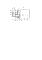
- FIG. 1(A) is a partial front view schematically showing an automatically driving ground vehicle according to this embodiment
- FIG. 1(B) is a functional block diagram schematically showing a drive steering control system according to this embodiment.
- FIG. 2(A) is a partial front view showing in detail the autonomous driving ground vehicle of this embodiment
- FIG. 2(B) is a functional block diagram of the autonomous navigation unit, vehicle control device, and drive steering control device.
- FIG. 2C is a functional block diagram of a drive steering control device in the drive steering control system.
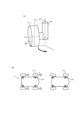
- FIG. 3(A) is a schematic diagram showing the steering of the subject wheel and rotation around the axle
- FIG. 3(B) is a plan view schematically showing a situation in which the autonomous driving ground vehicle accelerates forward.
- FIG. 3(A) is a schematic diagram showing the steering of the subject wheel and rotation around the axle
- FIG. 3(B) is a plan view schematically showing a situation in which the autonomous driving ground vehicle accelerates forward.
- FIG. 3(A) is a
- FIGS. 5A and 5B are functional block diagrams of an autonomous navigation unit, a vehicle control device, and a drive steering control device according to modifications of the present embodiment.
- a driving and steering control system, a built-in driving and steering unit system, a built-in driving and steering unit, and an autonomous driving ground vehicle will be described below with reference to the drawings. It should be noted that the embodiment described below is merely an example. The present invention is not to be construed in any way as limited by the embodiments described below.
- FIG. 1(A) is a partial front view schematically showing an automatically driving ground vehicle according to this embodiment.
- the self-driving ground vehicle 1 comprises a target wheel 11 , a propulsion motor 12 , a steering motor 13 , a steering shaft 14 and a drive steering control system 15 .
- the self-driving ground vehicle 1 has a pair of left and right front wheels and a pair of left and right rear wheels, that is, four wheels.
- the target wheel 11 is the right front wheel, which is one of the pair of left and right front wheels.
- the propulsion motor 12 is an in-wheel motor provided inside the wheel of the target wheel 11 .
- the output shaft of the propulsion motor 12 is connected to the axle 111 of the target wheel 11 .
- the propulsion motor 12 rotates the target wheel 11 around the target wheel axle 111 .
- the steering motor 13 is an in-wheel motor provided inside the wheel of the target wheel 11 .
- the output shaft of the steering motor 13 extends in the left-right direction.
- the output shaft of the steering motor 13 is connected to the steering shaft 14 via a bevel gear.
- the steering motor 13 steers the target wheel 11 left and right.
- the steering shaft 14 extends vertically and is connected to the output shaft of the steering motor 13 .
- the steering shaft 14 is arranged between the target wheel 11 and the vehicle body of the automatically driving ground vehicle 1 in the left-right direction.
- the steering shaft 14 is configured to steer the target wheel 11 left and right when the steering motor 13 operates.
- the steering shaft 14 is non-rotatably fixed to the vehicle body of the automatic driving ground vehicle 1 .
- the steering shaft 14 is arranged to have a scrub radius S with respect to the target wheel 11 .
- FIG. 1(B) is a functional block diagram schematically showing the drive steering control system of this embodiment.
- the drive steering control system 15 includes an acquisition section 1511 and a motor information processing section 1512 .
- the acquisition unit 1511 can acquire propulsion motor operation instruction information indicating to operate the propulsion motor 12 and steering motor operation instruction information indicating to operate the steering motor 13 from the upper control unit 20 for the drive steering control system 15 . .
- the motor information processing unit 1512 changes the operating parameters of the steering motor 13 and the operating parameters of the propulsion motor 12 based on the steering motor operation instruction information acquired by the acquiring unit 1511, and changes the operating parameters of the propulsion motor 12. Based on the propulsion motor actuation instruction information, the propulsion motor 12 is operated and the steering motor 13 is operated so that the operating parameter of the propulsion motor 12 is changed and the operating parameter of the steering motor 13 is changed.
- FIG. 2(A) is a partial front view showing the details of the self-driving ground vehicle of this embodiment.
- the self-driving ground vehicle 1 further comprises an autonomous navigation unit 16 and a vehicle control device 17 .
- the autonomous navigation unit 16 and the vehicle control device 17 are attached to the vehicle body 19 of the self-driving ground vehicle 1 .
- the drive steering control system 15 comprises a drive steering control device 151 .
- FIG. 2(B) is a functional block diagram of the autonomous navigation unit 16, vehicle control device 17, and drive steering control device 151.
- the autonomous navigation unit 16 determines the route that the autonomous ground vehicle 1 should travel. For example, the autonomous navigation unit 16 determines the route that the autonomous driving ground vehicle 1 should travel based on information from a camera mounted on the vehicle body, GPS, or the like. After determining the route, the autonomous navigation unit 16 transmits the target vehicle speed and the target turning radius to the vehicle control device 17 .
- the vehicle control device 17 determines the target rotation speed of the propulsion motor 12 based on the target vehicle speed received from the autonomous navigation unit 16 .
- the vehicle control device 17 determines the target steering angle of the steering motor 13 based on the target turning radius received from the autonomous navigation unit 16 .
- the vehicle control device 17 transmits the determined target rotation speed and target turning radius to the drive steering control device 151 .
- This target rotational speed corresponds to propulsion motor actuation instruction information indicating that the propulsion motor 12 is to be operated.
- the target turning radius corresponds to steering motor activation instruction information indicating that the steering motor 13 should be activated. That is, in this embodiment, the vehicle control device 17 corresponds to a higher-level control section for the drive steering control system 15 .
- the propulsion motor actuation indication information and the steering motor actuation indication information do not include information about the scrub radius S and are not based on the scrub radius S.
- FIG. 2(C) is a functional block diagram of the drive steering control device 151 in the drive steering control system 15. As shown in FIG.
- the drive steering control device 151 includes an acquisition section 1511 and a motor information processing section 1512 .
- Acquisition unit 1511 receives propulsion motor actuation instruction information indicating actuation of propulsion motor 12 and steering motor actuation instruction information indicating actuation of steering motor 13 from a host control unit (vehicle control device 17) for drive steering control system 15. can be obtained. Acquisition unit 1511 , upon acquiring the propulsion motor actuation instruction information and the steering motor actuation instruction information, sends them to motor information processing unit 1512 .
- the motor information processing unit 1512 changes the operating parameters of the steering motor 13 and changes the operating parameters of the propulsion motor 12 based on the steering motor operation instruction information acquired by the acquiring unit 1511, and the motor information processing unit 1512 , the propulsion motor 12 and the steering motor 13 are operated so as to change the operating parameter of the propulsion motor 12 and the operating parameter of the steering motor 13 based on the propulsion motor operation instruction information acquired by the acquiring unit 1511.
- the motor information processing section 1512 includes a geometry calculation section 1513, a rotation speed calculation section 1514, torque calculation sections 1515 and 1517, a speed interference calculation section 1516, a current conversion section 1518 and 1520, and a torque It includes an interference calculation unit 1519 and motor drivers 1521 and 1522 .
- the geometric calculation unit 1513 geometrically calculates a corrected target steering angle considering the scrub radius S based on the steering motor actuation instruction information not considering the scrub radius S received from the acquisition unit 1511 .
- Geometry calculation section 1513 sends the calculated corrected target steering angle to rotational speed calculation section 1514 .
- the rotation speed calculation unit 1514 receives the corrected target steering angle from the geometric calculation unit 1513, and calculates the steering motor 13 required to steer the target wheel from the current steering angle of the target wheel to the corrected target steering angle. Calculate the target rpm.
- the rotation speed calculation unit 1514 sends the calculated target rotation speed of the steering motor 13 to the torque calculation unit 1515 and the speed interference calculation unit 1516 .
- the torque calculation unit 1515 calculates the provisional output torque of the steering motor 13 from the target rotation speed of the steering motor 13 received from the rotation speed calculation unit 1514 .
- the torque calculation section 1515 sends the calculated provisional output torque of the steering motor 13 to the torque interference calculation section 1519 .
- speed interference calculation section 1516 calculates the product of the target rotation speed of steering motor 13 received from rotation speed calculation section 1514 and a predetermined coefficient Ks, and sends the product to torque calculation section 1517 .
- the torque calculation unit 1517 based on the propulsion motor operation instruction information received from the acquisition unit 1511 and the product of the target rotation speed of the steering motor 13 received from the speed interference calculation unit 1516 and a predetermined coefficient Ks, The rotation speed of the target wheel 11 indicated in the propulsion motor operation instruction information is corrected, and the output torque (target torque) of the propulsion motor 12 is determined.
- the torque calculation unit 1517 sends the determined target torque of the propulsion motor 12 to the current conversion unit 1518 and the torque interference calculation unit 1519 .
- the torque interference calculation unit 1519 calculates the product of the target torque of the propulsion motor 12 received from the torque calculation unit 1517 and a predetermined coefficient Kt.
- the torque interference calculation unit 1519 subtracts the product of the calculated target torque of the propulsion motor 12 and a predetermined coefficient Kt from the provisional output torque of the steering motor 13 received from the torque calculation unit 1515 to obtain the output torque of the steering motor 13 (target torque).
- the torque interference calculator 1519 sends the calculated target torque of the steering motor 13 to the current converter 1520 .
- the current conversion section 1520 converts the target torque of the steering motor 13 received from the torque interference calculation section 1519 into a target current value and sends it to the motor driver 1521 . Also, the current converter 1518 converts the target torque of the propulsion motor 12 received from the torque calculator 1517 into a target current value, and sends the target current value to the motor driver 1522 .
- the motor driver 1522 causes the current of the target current value received from the current converter 1518 to flow through the propulsion motor 12 . Also, the motor driver 1521 supplies the current of the target current value received from the current conversion unit 1520 to the steering motor 13 .
- FIG. 3A is a schematic diagram showing steering of the target wheel 11 and rotation around the axle 111.
- FIG. In a vehicle having a scrub radius S, when the target wheel 11 is steered while the vehicle is stopped, the target wheel 11 is rotated around the steering shaft 14 by the steering motor 13 and steered. At this time, since the propulsion motor 12 is stopped, the target wheel 11 does not rotate around the axle 111 . Therefore, the target wheel 11 is steered while rubbing against the ground.
- the drive steering control system 15 of this embodiment when the steering motor activation instruction information for activating the steering motor 13 is obtained, not only the steering motor 13 but also the propulsion motor 12 is activated. When the target wheel 11 is steered, the target wheel 11 can be rotated about the axle 111 . Therefore, speed interference that hinders steering of the target wheel 11 by the propulsion motor 12 described above is suppressed.
- FIG. 3(B) is a plan view schematically showing a state in which the automatically driven ground vehicle 1 accelerates forward.
- a vehicle with a scrub radius S when the subject wheel 11 is not steered and the vehicle accelerates straight forward, the subject wheel 11 receives a forward reaction force F from the ground. Due to this reaction force F, the target wheel 11 is rotated around the steering shaft 14, that is, steered. At this time, since the steering motor 13 is stopped, the steering angle of the target wheel 11 changes from the target value.
- the drive steering control system 15 of the present embodiment when the propulsion motor actuation instruction information for operating the propulsion motor 12 is acquired, not only the propulsion motor 12 but also the steering motor 13 is operated.
- both the speed interference and the torque interference between the propulsion motor 12 and the steering motor 13 can be suppressed in the self-driving ground vehicle 1 having the scrub radius S. can.
- the speed of the contact surface of the target wheel 11 by the propulsion motor 12 is represented by the product of the rotational speed W1 (rad/s) of the target wheel 11 around the axle 111 and the radius Rw (m) of the target wheel 11 .
- Equation (4) is derived from equations (1) to (3), and the coefficient Ks is obtained as shown in equation (5).
- Wa ⁇ (S/Rw) ⁇ (Za/Zb) ⁇ Wb (4)
- Ks ⁇ (S/Rw) ⁇ (Za/Zb) ⁇ (5)
- the steering moment Ms (N m) to be added to the target wheel 11 to suppress torque interference is calculated using the reaction force F (N) that the target wheel 11 receives from the ground and the scrub radius S, using the following formula (6 ).
- Ms -F ⁇ S (6)
- Equation (9) is derived from equations (6) to (8), and the coefficient Kt is obtained as shown in equation (10).
- Tb ⁇ (S/Rw) ⁇ (Za/Zb) ⁇ Ta (9)
- Kt ⁇ (S/Rw) ⁇ (Za/Zb) ⁇ (10)
- the drive steering control system 15 may comprise an embedded drive steering unit 18, as shown in FIG.
- the built-in drive and steering unit 18 comprises object wheels 11 , a propulsion motor 12 , a steering motor 13 and a steering shaft 14 .
- the built-in drive and steering unit 18 is attachable to and detachable from the vehicle body 19 of the self-driving ground vehicle 1 .
- the embedded drive steering unit 18 may or may not include a drive steering controller 151 .
- the drive steering controller 151 may be located on the vehicle body 19 .
- the drive steering control system 15 may include a vehicle control device 17 and a drive steering control device 151 .
- the autonomous navigation unit 16 includes the host controller 20 and transmits propulsion motor actuation instruction information and steering motor actuation instruction information to the drive steering control system 15 .
- the drive steering control system 15 may be configured with a vehicle control device 17 .
- the autonomous navigation unit 16 includes the host controller 20 and transmits propulsion motor actuation instruction information and steering motor actuation instruction information to the drive steering control system 15 .
- the vehicle control device 17 and the drive and steering control device 151 may each be arranged on the vehicle body 19 of the self-driving ground vehicle 1, or may be mounted on the target wheel 11 or the built-in drive and steering unit 18. may be placed.
Landscapes
- Engineering & Computer Science (AREA)
- Transportation (AREA)
- Mechanical Engineering (AREA)
- Chemical & Material Sciences (AREA)
- Combustion & Propulsion (AREA)
- Automation & Control Theory (AREA)
- Human Computer Interaction (AREA)
- Physics & Mathematics (AREA)
- Mathematical Physics (AREA)
- Power Engineering (AREA)
- Steering Control In Accordance With Driving Conditions (AREA)
Priority Applications (3)
| Application Number | Priority Date | Filing Date | Title |
|---|---|---|---|
| PCT/JP2021/047269 WO2023119407A1 (ja) | 2021-12-21 | 2021-12-21 | 駆動操舵制御システム、組込式駆動操舵ユニットシステム、組込式駆動操舵ユニット及び自動運転地上車両 |
| JP2023568811A JPWO2023119407A1 (https=) | 2021-12-21 | 2021-12-21 | |
| US18/749,549 US20240336249A1 (en) | 2021-12-21 | 2024-06-20 | Driving and steering control system, built-in driving and steering unit system, built-in driving and steering unit, and autonomous ground vehicle |
Applications Claiming Priority (1)
| Application Number | Priority Date | Filing Date | Title |
|---|---|---|---|
| PCT/JP2021/047269 WO2023119407A1 (ja) | 2021-12-21 | 2021-12-21 | 駆動操舵制御システム、組込式駆動操舵ユニットシステム、組込式駆動操舵ユニット及び自動運転地上車両 |
Related Child Applications (1)
| Application Number | Title | Priority Date | Filing Date |
|---|---|---|---|
| US18/749,549 Continuation-In-Part US20240336249A1 (en) | 2021-12-21 | 2024-06-20 | Driving and steering control system, built-in driving and steering unit system, built-in driving and steering unit, and autonomous ground vehicle |
Publications (1)
| Publication Number | Publication Date |
|---|---|
| WO2023119407A1 true WO2023119407A1 (ja) | 2023-06-29 |
Family
ID=86901639
Family Applications (1)
| Application Number | Title | Priority Date | Filing Date |
|---|---|---|---|
| PCT/JP2021/047269 Ceased WO2023119407A1 (ja) | 2021-12-21 | 2021-12-21 | 駆動操舵制御システム、組込式駆動操舵ユニットシステム、組込式駆動操舵ユニット及び自動運転地上車両 |
Country Status (3)
| Country | Link |
|---|---|
| US (1) | US20240336249A1 (https=) |
| JP (1) | JPWO2023119407A1 (https=) |
| WO (1) | WO2023119407A1 (https=) |
Citations (8)
| Publication number | Priority date | Publication date | Assignee | Title |
|---|---|---|---|---|
| JP2005145141A (ja) * | 2003-11-12 | 2005-06-09 | Toyota Motor Corp | 車両のパワーステアリング制御装置 |
| JP2007076579A (ja) * | 2005-09-16 | 2007-03-29 | Toyota Motor Corp | 車輌の操舵補助力制御装置 |
| JP2007076578A (ja) * | 2005-09-16 | 2007-03-29 | Toyota Motor Corp | 車輌の操舵補助力制御装置 |
| JP2007336679A (ja) * | 2006-06-14 | 2007-12-27 | Nissan Motor Co Ltd | 電動車両の駆動力推定装置、自動車および電動車両の駆動力推定方法 |
| JP2014023199A (ja) * | 2012-07-13 | 2014-02-03 | Ntn Corp | 転舵アシスト制御装置 |
| US20180201255A1 (en) * | 2015-07-10 | 2018-07-19 | Byd Company Limited | Method and system for controlling vehicle with four-wheel drive and vehicle |
| JP2020131739A (ja) * | 2019-02-13 | 2020-08-31 | Ntn株式会社 | 車両の姿勢制御装置 |
| WO2021141018A1 (ja) * | 2020-01-06 | 2021-07-15 | Ntn株式会社 | 車両の旋回制御装置 |
Family Cites Families (3)
| Publication number | Priority date | Publication date | Assignee | Title |
|---|---|---|---|---|
| US7418328B2 (en) * | 2006-05-08 | 2008-08-26 | Deere & Company | Steering logic for self-propelled mower |
| JP5851861B2 (ja) * | 2012-01-30 | 2016-02-03 | Ntn株式会社 | 電気自動車 |
| US20220355855A1 (en) * | 2021-07-22 | 2022-11-10 | Atlis Motor Vehicles, Inc. | System for a Vehicle that Compensates for Vehicle Spin |
-
2021
- 2021-12-21 WO PCT/JP2021/047269 patent/WO2023119407A1/ja not_active Ceased
- 2021-12-21 JP JP2023568811A patent/JPWO2023119407A1/ja not_active Ceased
-
2024
- 2024-06-20 US US18/749,549 patent/US20240336249A1/en active Pending
Patent Citations (8)
| Publication number | Priority date | Publication date | Assignee | Title |
|---|---|---|---|---|
| JP2005145141A (ja) * | 2003-11-12 | 2005-06-09 | Toyota Motor Corp | 車両のパワーステアリング制御装置 |
| JP2007076579A (ja) * | 2005-09-16 | 2007-03-29 | Toyota Motor Corp | 車輌の操舵補助力制御装置 |
| JP2007076578A (ja) * | 2005-09-16 | 2007-03-29 | Toyota Motor Corp | 車輌の操舵補助力制御装置 |
| JP2007336679A (ja) * | 2006-06-14 | 2007-12-27 | Nissan Motor Co Ltd | 電動車両の駆動力推定装置、自動車および電動車両の駆動力推定方法 |
| JP2014023199A (ja) * | 2012-07-13 | 2014-02-03 | Ntn Corp | 転舵アシスト制御装置 |
| US20180201255A1 (en) * | 2015-07-10 | 2018-07-19 | Byd Company Limited | Method and system for controlling vehicle with four-wheel drive and vehicle |
| JP2020131739A (ja) * | 2019-02-13 | 2020-08-31 | Ntn株式会社 | 車両の姿勢制御装置 |
| WO2021141018A1 (ja) * | 2020-01-06 | 2021-07-15 | Ntn株式会社 | 車両の旋回制御装置 |
Also Published As
| Publication number | Publication date |
|---|---|
| US20240336249A1 (en) | 2024-10-10 |
| JPWO2023119407A1 (https=) | 2023-06-29 |
Similar Documents
| Publication | Publication Date | Title |
|---|---|---|
| US9764734B1 (en) | Stability control system | |
| JP5463463B2 (ja) | 乗用型対地作業車両 | |
| US20180297636A1 (en) | Three-wheeled tilting vehicle | |
| US20070295545A1 (en) | Differential Steering and Traction Control For Electrically Propelled Mower | |
| EP3371036B1 (en) | Maintenance vehicle | |
| US20110224872A1 (en) | System And Method To Control Vehicle Steering | |
| KR20130047309A (ko) | 인휠 시스템을 이용한 차량 제어 방법 | |
| JP7244994B2 (ja) | 操舵機能付ハブユニット、操舵システム、および操舵機能付ハブユニットを備えた車両 | |
| JP6898428B2 (ja) | 車両 | |
| KR101311226B1 (ko) | 독립휠 제어형 다축 조향장치 | |
| JP7068882B2 (ja) | ステアリングシステムおよびこれを備えた車両 | |
| JP2019171908A (ja) | ステアリングシステムおよびこれを備えた車両 | |
| JP7366281B2 (ja) | 二輪車 | |
| WO2018078879A1 (ja) | 作業車両 | |
| KR20230020965A (ko) | 전방향 차량(omnidirectional vehicle) | |
| CN111619699A (zh) | Agv移动平台及其控制方法和控制装置 | |
| JP2019171904A (ja) | ステアリングシステムおよびこれを備えた車両 | |
| WO2019189096A1 (ja) | ステアリングシステムおよびこれを備えた車両 | |
| KR101432535B1 (ko) | 차륜별 독립 조향장치를 구비하는 차량의 조향 제어 방법 | |
| KR101597702B1 (ko) | 세바퀴 전기 자동차의 제어방법 | |
| WO2023119407A1 (ja) | 駆動操舵制御システム、組込式駆動操舵ユニットシステム、組込式駆動操舵ユニット及び自動運転地上車両 | |
| JP5422257B2 (ja) | 車両 | |
| CN207747932U (zh) | 可全轮转向的电动车转向系统 | |
| JP5971554B2 (ja) | 操舵補助装置 | |
| JP2015181473A (ja) | 芝刈り車両 |
Legal Events
| Date | Code | Title | Description |
|---|---|---|---|
| 121 | Ep: the epo has been informed by wipo that ep was designated in this application |
Ref document number: 21968844 Country of ref document: EP Kind code of ref document: A1 |
|
| WWE | Wipo information: entry into national phase |
Ref document number: 2023568811 Country of ref document: JP |
|
| NENP | Non-entry into the national phase |
Ref country code: DE |
|
| 122 | Ep: pct application non-entry in european phase |
Ref document number: 21968844 Country of ref document: EP Kind code of ref document: A1 |