WO2023112866A1 - 取付部材付きアンテナ装置及びアンテナ装置の取付構造 - Google Patents
取付部材付きアンテナ装置及びアンテナ装置の取付構造 Download PDFInfo
- Publication number
- WO2023112866A1 WO2023112866A1 PCT/JP2022/045566 JP2022045566W WO2023112866A1 WO 2023112866 A1 WO2023112866 A1 WO 2023112866A1 JP 2022045566 W JP2022045566 W JP 2022045566W WO 2023112866 A1 WO2023112866 A1 WO 2023112866A1
- Authority
- WO
- WIPO (PCT)
- Prior art keywords
- mounting member
- antenna device
- antenna
- straight line
- region
- Prior art date
- Legal status (The legal status is an assumption and is not a legal conclusion. Google has not performed a legal analysis and makes no representation as to the accuracy of the status listed.)
- Ceased
Links
Images


Classifications
-
- H—ELECTRICITY
- H01—ELECTRIC ELEMENTS
- H01Q—ANTENNAS, i.e. RADIO AERIALS
- H01Q1/00—Details of, or arrangements associated with, antennas
- H01Q1/27—Adaptation for use in or on movable bodies
- H01Q1/32—Adaptation for use in or on road or rail vehicles
- H01Q1/325—Adaptation for use in or on road or rail vehicles characterised by the location of the antenna on the vehicle
- H01Q1/3291—Adaptation for use in or on road or rail vehicles characterised by the location of the antenna on the vehicle mounted in or on other locations inside the vehicle or vehicle body
-
- H—ELECTRICITY
- H01—ELECTRIC ELEMENTS
- H01Q—ANTENNAS, i.e. RADIO AERIALS
- H01Q1/00—Details of, or arrangements associated with, antennas
- H01Q1/12—Supports; Mounting means
- H01Q1/1207—Supports; Mounting means for fastening a rigid aerial element
- H01Q1/1221—Supports; Mounting means for fastening a rigid aerial element onto a wall
-
- H—ELECTRICITY
- H01—ELECTRIC ELEMENTS
- H01Q—ANTENNAS, i.e. RADIO AERIALS
- H01Q1/00—Details of, or arrangements associated with, antennas
- H01Q1/12—Supports; Mounting means
- H01Q1/22—Supports; Mounting means by structural association with other equipment or articles
-
- H—ELECTRICITY
- H01—ELECTRIC ELEMENTS
- H01Q—ANTENNAS, i.e. RADIO AERIALS
- H01Q1/00—Details of, or arrangements associated with, antennas
- H01Q1/27—Adaptation for use in or on movable bodies
- H01Q1/32—Adaptation for use in or on road or rail vehicles
-
- H—ELECTRICITY
- H01—ELECTRIC ELEMENTS
- H01Q—ANTENNAS, i.e. RADIO AERIALS
- H01Q1/00—Details of, or arrangements associated with, antennas
- H01Q1/27—Adaptation for use in or on movable bodies
- H01Q1/32—Adaptation for use in or on road or rail vehicles
- H01Q1/325—Adaptation for use in or on road or rail vehicles characterised by the location of the antenna on the vehicle
- H01Q1/3275—Adaptation for use in or on road or rail vehicles characterised by the location of the antenna on the vehicle mounted on a horizontal surface of the vehicle, e.g. on roof, hood, trunk
-
- H—ELECTRICITY
- H01—ELECTRIC ELEMENTS
- H01Q—ANTENNAS, i.e. RADIO AERIALS
- H01Q13/00—Waveguide horns or mouths; Slot antennas; Leaky-waveguide antennas; Equivalent structures causing radiation along the transmission path of a guided wave
- H01Q13/10—Resonant slot antennas
-
- H—ELECTRICITY
- H01—ELECTRIC ELEMENTS
- H01Q—ANTENNAS, i.e. RADIO AERIALS
- H01Q9/00—Electrically-short antennas having dimensions not more than twice the operating wavelength and consisting of conductive active radiating elements
- H01Q9/04—Resonant antennas
- H01Q9/0407—Substantially flat resonant element parallel to ground plane, e.g. patch antenna
Definitions
- the present invention relates to an antenna device with a mounting member and a mounting structure for the antenna device.
- V2X Vehicle to Everything
- a V2X that can transmit and receive vertically polarized waves in a frequency band (5.8 GHz band (Japan) or 5.9 GHz band (Europe and the United States)) that satisfies the V2X communication standard with a desired gain.
- Antenna is required.
- a V2X antenna mounted on a vehicle is required to have a stable directivity that can achieve the desired antenna gain in a range of ⁇ 90° (180°) to the left and right of the front of the vehicle (vehicle traveling direction) on the horizontal plane. ing.
- Japanese Patent Application Laid-Open No. 2019-75644 discloses an antenna for V2X communication arranged in the vehicle interior such that the radiation surface of the radiation element faces the windshield or the rear glass.
- a metal bracket is preferably used in order to stably fix the radiation surface of the V2X antenna to the vehicle so that it faces the windshield and rear glass from the inside of the passenger compartment.
- a linearly polarized antenna such as a V2X antenna
- the transmission/reception characteristics (gain) of radio waves due to the metal change the antenna gain decreases, and the desired Directivity may not be obtained.
- the present invention provides an antenna device with a mounting member and a mounting structure for the antenna device that can stably mount an antenna on a vehicle, suppress a decrease in antenna gain, and achieve desired directivity. aim.
- An antenna device with a mounting member comprises: an antenna having a radiation plate having a radiation surface for radiating linearly polarized waves in a predetermined frequency band; a housing portion housing at least part of the antenna; a mounting member that is attached to a vehicle; and a metal member that is formed in an elongated shape at one end of the mounting member and that abuts against the rear surface of the housing portion on the side opposite to the radiation surface side of the radiation plate to fix the housing portion.
- the fixing portion is: It is arranged between a first region formed on the back surface on one side in the extending direction of the first straight line and a second region formed on the back surface on the other side in the extending direction of the first straight line.
- the antenna device with mounting member according to the present invention it is possible to stably mount the antenna on the vehicle, suppress a decrease in antenna gain, and achieve desired directivity.
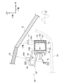
- FIG. 1 is a plan view of a vehicle, to which an antenna device with a mounting member according to the first embodiment is attached, viewed from a vertical direction;
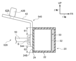
- FIG. FIG. 2 is an exploded cross-sectional view showing a state in which the antenna device with a mounting member according to the first embodiment is mounted on a windshield, and shows a cross section taken along line AA of FIG. 1;
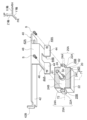
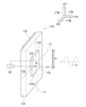
- FIG. 2 is an exploded perspective view showing the antenna device with a mounting member according to the first embodiment as seen obliquely from the rear;
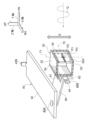
- 1 is a perspective view of an antenna device with a mounting member according to a first embodiment;
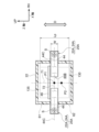
- FIG. FIG. 2 is a plan view showing the antenna according to the first embodiment as seen from the plate thickness direction of the radiation plate;
- FIG. 2 is a plan view showing the antenna device with a mounting member according to the first embodiment, viewed from the plate thickness direction of the radiation plate;
- FIG. 4 is a cross-sectional view showing an antenna device of a comparative example/reference example as viewed from the side, and shows an antenna device with a mounting member serving as a comparative example;
- FIG. 4 is a cross-sectional view showing an antenna device of a comparative example/reference example as viewed from the side, and shows an antenna device without a mounting member serving as a reference example;
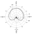
- FIG. 5 is an analysis diagram showing analysis results of directivity characteristics;
- FIG. 2 is an exploded cross-sectional view showing a state in which the antenna device with a mounting member according to the second embodiment is mounted on a windshield, and shows a cross section taken along line AA of FIG. 1;
- FIG. 2 is an exploded cross-sectional view showing a state in which the antenna device with a mounting member according to the third embodiment is mounted on a windshield, and shows a cross section taken along line AA in FIG. 1; It is a perspective view which shows the antenna based on 4th Embodiment seen from diagonally forward.
- FIG. 11 is a plan view showing an antenna device with a mounting member according to a fourth embodiment, viewed from the plate thickness direction of the radiation plate;
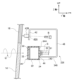
- FIG. 2 is an exploded cross-sectional view showing a state in which an antenna device with a mounting member according to another embodiment is mounted on a rear glass, and shows a BB cross section in FIG. 1;
- the X-axis shown as appropriate in each drawing is parallel to the vehicle width direction
- the Y-axis is parallel to the vehicle front-rear direction
- the Z-axis is parallel to the vehicle vertical direction.
- Arrow FR indicates the front in the vehicle longitudinal direction
- arrow UP indicates the upper side in the vehicle vertical direction
- arrow RH indicates the right side in the vehicle width direction.
- the XY plane is a plane passing through the X and Y axes
- the XZ plane is a plane passing through the X and Z axes
- the YZ plane is a plane passing through the Y and Z axes.
- the vehicle 10 is positioned on a horizontal plane, the vertical direction of the vehicle matches the vertical direction, the XY plane matches the horizontal plane, and the vertical direction corresponds to the normal direction to the horizontal plane. Also, the direction in which the vertically polarized wave Q oscillates is defined as the oscillation direction D. As shown in FIG. Also, in each figure, only the radiation plate 32 of the antenna 30 is shown for convenience, and other configurations are appropriately omitted.
- FIG. 1 is a plan view of a vehicle on which an antenna device 28 with a mounting member is mounted, viewed from the vertical direction.
- a vehicle 10 includes a windshield 12 as a glass plate and a rear glass 14 .
- the windshield 12 is attached to a metal frame (for example, a metal flange) 16 of the vehicle body with an adhesive such as urethane resin.
- the antenna device 28 (128, 228) with the mounting member is provided at the center in the vehicle width direction, but is offset from the center in the vehicle width direction (X-axis direction). It may be attached near the top of the shield 12 .
- an antenna device 328 with a mounting member may also be mounted in the vicinity of the upper portion of the rear glass 14 shifted in the vehicle width direction (X-axis direction) from the center in the vehicle width direction.
- the mounting member-equipped antenna device 328 the mounting member-equipped antenna device 28 of the present embodiment (mounting member-equipped antenna devices 128 and 228 to be described later) may be attached. That is, the mounting member-equipped antenna device 28 is preferably attached to at least one of the vicinity of the upper portion of the windshield 12 and the vicinity of the upper portion of the rear glass 14 .
- the antenna device 28 with mounting member will be described as being mounted near the top of the windshield 12 .
- FIG. 2 is an exploded cross-sectional view including the mounting member-equipped antenna device 28 taken along line AA of FIG. 1, and FIG. 3 is an exploded perspective view showing the mounting member-equipped antenna device 28 as seen obliquely from the rear.
- the mounting member-equipped antenna device 28 includes an antenna 30, a housing portion 20 that houses the antenna 30, a mounting member 40 that mounts the housing portion 20 to the metal frame 16 of the vehicle 10, and is attached to a vehicle body such as a metal frame 16 by bolts B as fastening members.
- the mounting member 40 may be attached to the metal frame 16 with weld bolts and nuts welded to the metal frame 16 .
- FIG. 4 is a perspective view showing the mounting member-equipped antenna device 28, and FIG. 5 is a plan view of the antenna 30 viewed from the plate thickness direction of the radiation plate 32.
- the antenna 30 is a vertically polarized wave (an example of a linearly polarized wave) Q of 5.8 GHz band or 5.9 GHz band used in vehicle-to-vehicle communication and road-to-vehicle communication, for example. can be applied as a V2X antenna for transmitting and receiving.
- 4 is shown without the coaxial cable 50 for the sake of simplification, for example, as shown in FIG. , and its end is placed in the housing portion 20 .
- the antenna 30 illustrated in FIGS. 4 and 5 is a slot antenna applicable to V2X antennas.
- the antenna 30 has a radiation plate (radiation conductor) 32.
- a radiation plate (radiation conductor) 32 As shown in FIGS. A front surface of the radiation plate 32 in the vehicle front-rear direction constitutes a radiation surface 32A.
- the radiation surface 32A radiates, for example, vertically polarized waves Q of 5.8 GHz band or 5.9 GHz band used in V2X.
- the radiation plate 32 has a slot 32B formed as an opening that divides at least part of the radiation surface 32A into a surface portion 35 and a surface portion 36 .
- the slot 32B extends in the extending direction of the second straight line 72 .
- the surface portion 35 is a conductive portion located on the positive side of the slot 32B in the Z-axis direction.
- the surface portion 36 is a conductive portion located on the negative side of the slot 32B in the Z-axis direction.
- the surface portion 35 has a feeding point P2 and the surface portion 36 has a feeding point P3.
- the openings may extend obliquely at an acute angle of more than 0°.
- a pair of feeding points P2 and P3 are locations where the coaxial cable 50 is electrically connected.
- Feeding point P2 is electrically connected to the ground portion of coaxial cable 50 .
- Feeding point P3 is electrically connected to the signal line of coaxial cable 50 .
- the feeding point P2 may be electrically connected to the signal line of the coaxial cable 50. In this case, the feeding point P3 is electrically connected to the ground portion of the coaxial cable 50.
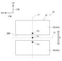
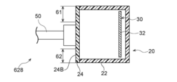
- FIG. 6 is a plan view showing the mounting member-equipped antenna device 28 as seen from the thickness direction of the radiation plate 32 on the side opposite to the radiation surface 32A side.
- a straight line that passes through the center of gravity P1 of the radiation plate 32 and is the vibration direction D of the vertically polarized wave Q when viewed from the plate thickness direction of the radiation plate 32 is called a first straight line 71.
- a straight line that is orthogonal to the first straight line 71 and passes through the center of gravity P1 of the radiation plate 32 is defined as a second straight line 72 .
- the feeding point P2 and the feeding point P3 of the antenna 30 are located on the first straight line 71 at positions different from the center of gravity P1 of the radiation plate 32 .
- the first straight line 71 can be a straight line passing through the center of gravity P1 of the radiation plate 32 and the feeding point P2 or the feeding point P3 when viewed from the thickness direction of the radiation plate 32 .
- the first straight line 71 can be a straight line extending in a direction perpendicular to the longitudinal direction of the slot 32B.
- the slot 32B may be arranged to extend in the vehicle width direction (X-axis direction) while deviating from the second straight line in the Z-axis direction. may match. Even in that case, the center of gravity P1, the feeding point P2, and the feeding point P3 are arranged on the first straight line 71.
- the housing portion 20 is made of resin, for example, and is formed into a box shape by a case portion 22 and a cover portion 24 .
- the case portion 22 is formed in, for example, a box shape with an open rear surface in the vehicle front-rear direction, and the antenna 30 is housed inside the case portion 22 .
- Convex portions 22A projecting outward in the vehicle width direction may be formed on both side surfaces of the case portion 22 in the vehicle width direction. As shown in FIG. 6 , the convex portion 22A protrudes along the second straight line 72 when viewed from the plate thickness direction of the radiation plate 32 .
- the case part 22 may be formed in a box shape with an open surface on the front side of the vehicle, and may have a part that is not partially covered without being limited to the structure that completely covers the antenna 30 .
- the cover portion 24 is formed in a plate shape and is positioned on the opposite side of the radiation plate 32 of the antenna 30 from the radiation surface 32A so as to cover the opening of the case portion 22. It is attached to the case part 22 .
- Convex portions 24A projecting outward in the vehicle width direction are formed on both side surfaces of the cover portion 24 in the vehicle width direction. As shown in FIG. 6 , the convex portion 24A protrudes along the second straight line 72 when viewed from the plate thickness direction of the radiation plate 32 . 22 A of convex parts and 24 A of convex parts comprise 25 A of protrusion parts of the accommodating part 20. As shown in FIG.
- the projecting portion 25A is formed with a mounting hole 25B as a mounting portion for mounting the fixing portion 44 to the housing portion 20.
- the fixing portion 44 is attached to the housing portion 20 by fastening the cover portion 24 and the fixing portion 44 together with screws S as metal fastening members in the attachment holes 25B.
- the attachment between the fixing portion 44 and the housing portion 20 is not limited to fixing with screws S, and various fixing structures can be adopted as long as they can be fixed mechanically.
- a cylindrical boss 24C extending rearward of the vehicle may be formed on the rear surface 24B of the cover portion 24 in the vehicle front-rear direction.
- An opening 24D inside the boss 24C is formed so as to pass through the cover portion 24.
- One end of a coaxial cable 50 as a feeder line is inserted into the opening 24D and electrically connected to the feeder points P2 and P3.
- the other end of coaxial cable 50 is connected to a control device that controls signals transmitted and received by antenna 30 .
- the opening provided in the back surface 24B of the cover part 24 may have any shape, and the presence or absence of the boss 24C is not a question.
- the feed line is not limited to coaxial cable, strip line, Various transmission lines for high frequency signal communication can be used such as microstripline, coplanar waveguide, GCPW (coplanar waveguide with ground plane), coplanar strip, slotline, waveguide.
- GCPW coplanar waveguide with ground plane
- coplanar strip slotline
- waveguide waveguide
- the mounting member 40 connects the housing portion 20 and the metal frame 16 of the vehicle 10 .
- the mounting member 40 is made of metal and includes a mounting portion 42 , a fixing portion 44 , an extending portion 46 and a connecting portion 48 .
- the mounting member 40 may be formed by mechanically joining multiple kinds of metals or by welding. Furthermore, the mounting member 40 may partially contain resin when a plurality of materials including metal are joined together. However, from the viewpoint of obtaining high rigidity, it is preferable that the mounting member 40 is made of metal and integrally formed. Hereinafter, unless otherwise specified, the mounting member 40 is assumed to be integrally formed of metal.
- the mounting portion 42 is formed at one end of the mounting member 40 .
- the mounting portion 42 is formed in a long rectangular plate shape extending in the vehicle width direction.
- the mounting portion 42 may include a through hole 42A penetrating in the plate thickness direction, and an extension portion 42B extending substantially upward from the side surface of the mounting portion 42 .
- the through-hole 42A is formed on the right side of the extending portion 46 in the vehicle width direction. As shown in FIG. 2, the mounting member 40 is mounted to the metal frame 16 of the vehicle 10 by means of bolts B as fastening members inserted into the through holes 42A.
- the through-hole 42A may be formed on the left side of the extending portion 46 in the vehicle width direction, or may be formed on both sides in the vehicle width direction.
- the extending portion 42B abuts on a convex portion (not shown) of the metal frame 16, thereby facilitating the positioning of the mounting member 40 with respect to the vehicle body.
- the fixing portion 44 is formed at the other end of the mounting member 40 .
- the fixed portion 44 is formed so as to extend in the vertical direction (Z-axis direction).
- FIG. 2 shows an example in which the case portion 22 has a rectangular cross section, and the fixed portion 44 is substantially parallel to the radiation surface 32A of the radiation plate 32 in the cross section of the case portion 22 .
- the case portion 22 may have a shape in which the fixed portion 44 and the radiation surface 32A are not parallel to each other in cross section, instead of a rectangular parallelepiped. A range of 15° is sufficient. Further, as shown in FIGS.
- the fixing portion 44 is formed in a long shape extending in the vehicle width direction, particularly in a long rectangular plate shape, but this shape can be arbitrarily designed.
- the longitudinal direction of the fixed portion 44 is preferably arranged along the extending direction of the second straight line 72 .
- through holes 44A penetrating in the plate thickness direction are formed in the vicinity of both ends in the longitudinal direction of the fixing portion 44 .
- One through hole 44A is formed at a position corresponding to one mounting hole 25B, and the other through hole 44A is formed at a position corresponding to the other mounting hole 25B.
- the fixing portion 44 is attached to the mounting hole 25B with a screw S while being in contact with the rear surface 24B of the accommodating portion 20, which is on the opposite side of the radiation plate 32 from the radiation surface 32A. As a result, the cover portion 24 and the fixed portion 44 are fastened together, and the fixed portion 44 is attached to the housing portion 20 .
- the fixed portion 44 when viewed from the plate thickness direction of the radiation plate 32, the fixed portion 44 is arranged such that the longitudinal axis 44C of the fixed portion 44 overlaps along the second straight line 72. In other words, when viewed from the thickness direction of the radiation plate 32 , the fixed portion 44 is preferably arranged such that the longitudinal axis 44 ⁇ /b>C of the fixed portion 44 coincides with the second straight line 72 .
- the fixed portion 44 may be arranged such that the longitudinal axis 44 ⁇ /b>C of the fixed portion 44 does not overlap the second straight line 72 .
- the fixing portion 44 only needs to be arranged so as to overlap at least the second straight line 72, and even if the second straight line 72 and the axis 44C do not completely coincide, It is preferable if these are in a parallel positional relationship.
- the fixing portion 44 is formed symmetrically with respect to the second straight line 72 when viewed from the plate thickness direction of the radiation plate 32, the antenna 30 can secure a desired antenna gain as will be described later. , it becomes easier to secure the desired directivity. Furthermore, when viewed from the plate thickness direction of the radiation plate 32 , it is more preferable that the fixed portion 44 is formed line-symmetrically with respect to the first straight line 71 .
- the fixed part 44 may have an opening 44B opening in the plate thickness direction near the center of gravity P1 of the radiation plate 32 .
- the opening 44B is preferably a through hole or notch larger than the outer diameter of the coaxial cable 50 .
- the structure is such that the coaxial cable 50 is easily connected to the antenna 30 through the opening 44B and the rear surface 24B.
- the fixing portion 44 may not have the opening portion 44B.
- the coaxial cable 50 may pass through a through hole (not shown) from above the housing portion 20 (in the direction along the negative Z-axis direction). You may connect to the antenna 30 via.
- the fixing portion 44 when viewed from the plate thickness direction of the radiation plate 32, has a first region 61 formed on the rear surface 24B on one side in the extending direction of the first straight line 71. and the second region 62 formed on the rear surface 24B on the other side in the extending direction of the first straight line 71 .
- the fixed portion 44 when viewed from the plate thickness direction of the radiation plate 32, has the first region 61 and the second region 61 on both sides in the extending direction of the first straight line 71 (both sides in the width direction of the fixed portion 44) on the rear surface 24B. region 62 .
- the width W of the fixing portion 44 along the first straight line 71 is formed to be narrower than the width LS along the first straight line 71 of the radiation plate 32 .
- the width W of the fixing portion 44 is not limited to a constant width, and may have different widths.
- the width W of the fixed portion 44 along the first straight line 71 and the width L S of the radiation plate 32 along the first straight line 71 preferably satisfy the following formula (1a), and preferably satisfy formula (1b), More preferably, the formula (1c) is satisfied. If W/L S is less than 0.01, the fixing strength between the fixing portion 44 and the housing portion 20 may be weak and unstable. Moreover, when W/L S exceeds 0.75, the antenna gain of the antenna 30 may decrease. 0.01 ⁇ W/ LS ⁇ 0.75 (1a) 0.05 ⁇ W/L S ⁇ 0.65 (1b) 0.10 ⁇ W/ LS ⁇ 0.50 (1c)
- the extending portion 46 extends from the upper end of the fixed portion 44 in the vertical direction of the vehicle in a direction away from the radiation plate 32 .
- the extending portion 46 extends away from the radiating plate 32 so as not to contact the rear surface 24B.
- the extending portion 46 is formed extending rearward of the vehicle from the upper end of the fixing portion 44 in the vertical direction of the vehicle.
- the extending portion 46 is formed so as not to contact the first region 61 and the second region 62 .
- the extending portion 46 may be formed so as to extend in a direction away from the radiation plate 32 from the lower end of the fixed portion 44 in the vertical direction of the vehicle or from an arbitrary position between the upper end and the lower end.
- the mounting member 40 is formed in a substantially L shape by the extending portion 46 and the fixing portion 44, but the shape is not limited to a substantially L shape.
- the extending portion 46 may be formed in a substantially T shape extending from between the upper end and the lower end of the fixed portion 44 in the vertical direction of the vehicle.
- the width of the extending portion 46 in the vehicle width direction is not particularly limited as long as the desired rigidity of the mounting member 40 is obtained.
- the connecting portion 48 connects one end of the extending portion 46 on the rear side in the vehicle front-rear direction and one end of the mounting portion 42 on the rear side in the vehicle front-rear direction.
- the width of the connecting portion 48 in the vehicle width direction is not particularly limited as long as the desired rigidity of the mounting member 40 is obtained.
- the mounting member 40 is formed in a substantially U shape by the mounting portion 42, the extending portion 46, and the connecting portion 48, but may be formed in a substantially J shape.
- the mounting member-equipped antenna device 28 configured in this manner is mounted on the metal frame 16 so that the angle ⁇ of the radiation surface 32A with respect to the vertical direction is within ⁇ 15°.
- the mounting member-equipped antenna device 28 is mounted on the metal frame 16 so that the first straight line 71 is within a range of ⁇ 15° with respect to the vertical direction of the vehicle.
- the mounting member-equipped antenna device 28 is mounted on the metal frame 16 such that the radiation surface 32A of the radiation plate 32 is separated from the windshield 12 .
- the angle ⁇ of the radiation surface 32A with respect to the vertical direction is preferably within ⁇ 10°, more preferably within ⁇ 5°, further preferably within ⁇ 3°, particularly preferably within ⁇ 1°, and most preferably 0°.
- the antenna device 28 with mounting member may also be mounted near the rear glass 14 .
- the antenna device 28 with mounting member is arranged in the vehicle interior, if it is arranged in a region where there is no conductor (conductive wire) such as a defogger (heating wire) formed on the main surface of the rear window 14, This is preferable because it makes it difficult for the antenna gain to decrease.
- conductive wire conductive wire
- defogger heating wire
- FIG. 7A is a cross-sectional view of an antenna device with a mounting member serving as a comparative example
- FIG. 7B is a cross-sectional view of an antenna device without a mounting member serving as a reference example.
- the antenna device 28 with a mounting member of "Example 1" which is an example of the first embodiment
- the antenna device with a mounting member 528 of "Example 2" as a comparative example and the “Example 3” and an antenna device 628 without mounting members were prepared.
- 7A and 7B detailed illustration of the connection between the coaxial cable 50 and the antenna 30 is omitted.
- the width W of the fixing portion 44 along the first straight line 71 is 10.0 mm
- the width L S of the radiation plate 32 along the first straight line 71 is 14 mm. .8 mm.
- the fixed portion 44 is arranged such that the longitudinal axis 44 ⁇ /b>C of the fixed portion 44 coincides with the second straight line 72 .
- extension 46 (shown in FIG. 2) includes mounting member 40 extending away from radiation plate 32 at an angle of approximately 90° to back surface 24B.
- An antenna device 528 with a mounting member of "Example 2", which is a comparative example, is configured such that the fixing portion 544 is in complete contact with the first region 61 formed on the rear surface 24B of the housing portion 20, as shown in FIG. 7A. is formed in
- the mounting member 540 is formed in a substantially L shape by the mounting portion 42 and the fixing portion 544 in a cross section along the YZ plane.
- An antenna device 628 without a mounting member of "Example 3", which is a reference example, is a model that does not have a fixing portion on the rear surface 24B of the housing portion so that it can be closed in FIG. 7B.
- the directivity analysis of the vertically polarized wave Q of 5.9 GHz in the horizontal plane was performed for the antenna device 28 with the mounting member, the antenna device 528 with the mounting member, and the antenna device 628 without the mounting member.
- FIG. 8 is a graph showing the directivity characteristics of the horizontal plane of each of the antenna devices of "Example 1" to “Example 3" when viewed from the vertical direction of the vehicle.
- the antenna device 628 without the mounting member of “Example 3”, which is a reference example has substantially the same size in directions of ⁇ 90° left and right with the front of the vehicle as the center. It can be seen that a small antenna gain is obtained, ie excellent directivity in a given angular range in the horizontal plane.
- the antenna device 28 with a mounting member according to the embodiment "Example 1" also has substantially the same size in directions of ⁇ 90° to the left and right with respect to the front of the vehicle. It can be seen that a small antenna gain is obtained, ie excellent directivity in a given angular range in the horizontal plane. Thus, the antenna device 28 with mounting member of the embodiment can obtain substantially the same antenna gain and directivity as the antenna device 628 without the mounting member of the reference example.
- the mounting member-equipped antenna device 528 of "Example 2" which is a comparative example, has a right side (RH) and a left side (LH) of the vehicle compared to “Example 1". ), the antenna gain is reduced and the directivity is disturbed. From this, the antenna device with mounting member 28 of "Example 1", which is an embodiment, can obtain a desired antenna gain and excellent directivity over a predetermined angle range (from LH side to FR side to RH side). .
- the fixing part 44 metal particularly by making the mounting member 40 integral with the metal, the housing part 20 is firmly fixed to the mounting member 40 . Therefore, the mounting member-equipped antenna device (antenna 30 ) can be stably mounted on the vehicle 10 .
- the fixing portion 44 is arranged between the first region 61 and the second region 62 .
- a first region 61 and a second region 62 are formed on the rear surface 24B of the rear surface 24B, where the metal fixing portion 44 is not arranged. That is, the antenna device 28 with a mounting member has a metal fixing portion at the open end where an electric field becomes strong when a current is applied to the antenna 30 in the vibration direction D of the vertically polarized wave Q by transmitting and receiving the vertically polarized wave Q. 44 is not formed.
- the antenna device 28 with a mounting member changes in the transmission/reception characteristics of the vertically polarized wave Q due to the metal fixing portion 44 are suppressed, and the antenna 30 can be stably mounted on the vehicle 10, and a decrease in antenna gain can be suppressed. , and by extension, the desired antenna directivity can be ensured.
- the fixing portion 44 is arranged so that the longitudinal axis 44C of the fixing portion 44 overlaps the second straight line 72 . Accordingly, in the extending direction of the first straight line 71, the first region 61 and the second region 62 where the metal fixing portion 44 is not arranged have substantially the same size. Furthermore, the region where the first region 61 and the radiation plate 32 as the conductor of the antenna 30 overlap and the region where the second region 62 and the radiation plate 32 as the conductor of the antenna 30 overlap have substantially the same shape and area. is.
- the change in the transmission/reception characteristics of the vertically polarized wave Q due to the metal fixing portion 44 can be further suppressed, the decrease in antenna gain can be further suppressed, and the desired antenna directivity can be ensured.
- the width W (of the first straight line 71) of the fixed part 44 is set so as to satisfy the above formula (1a).
- the fixed portion 44 and the housing portion 20 are connected to each other by forming a mounting hole 25B for mounting the fixed portion 44 to the housing portion 20 via a metal screw S in the projecting portion 25A. It is attached at a position away from 32. Therefore, the antenna device 28 with a mounting member can suppress a change in the transmission/reception characteristics of the vertically polarized wave Q due to the metal screw S, can suppress a decrease in antenna gain, and can ensure stable directivity.
- the mounting member-equipped antenna device 28 is located on both sides in the width direction of the metal fixing portion 44, and the first region 61 where the fixing portion 44 is not arranged. and the second region 62 have substantially the same size. Therefore, in the antenna device 28 with the mounting member, the change in the transmission/reception characteristics of the vertically polarized wave Q due to the metal fixing portion 44 is suppressed, the decrease in the antenna gain can be further suppressed, and the stable directivity can be ensured.
- the fixed portion 44 By forming the opening 44B in the fixed portion 44, the fixed portion 44 has a space for electrically connecting the coaxial cable 50 to the feeding point P2 and the feeding point P3. Therefore, it becomes easier to connect the coaxial cable 50 to a predetermined position.
- the mounting member-equipped antenna device 28 may further include a connector (not shown) for fixing the coaxial cable 50 and connecting it to the feeding point P2 and the feeding point P3.
- the mounting member 40 is made of metal, so that the housing portion 20 is firmly fixed to the vehicle 10 by the mounting member 40 . Therefore, the antenna 30 is stably attached to the vehicle 10 .
- the mounting member 40 of the mounting member-equipped antenna device 28 is integrally formed of metal, high rigidity can be obtained, so that the antenna 30 can be stably mounted at a desired position and posture.
- the antenna 30 of the mounting member-equipped antenna device 28 is attached to the vehicle 10 via the metal extending portion 46 , the antenna 30 can be firmly fixed to the vehicle 10 . Moreover, since the extension part 46 extends in the direction away from the radiation plate 32, the antenna device 28 with the mounting member suppresses changes in the transmission/reception characteristics of the vertically polarized wave Q due to the extension part 46 made of metal, thereby preventing a decrease in antenna gain. It can be suppressed, and by extension, stable directivity can be ensured.
- the mounting member-equipped antenna device 28 is provided so that the radiation surface 32A is within ⁇ 15° with respect to the vertical direction, so that the radiation surface 32A is oriented substantially horizontally. Therefore, the radiation surface 32A can transmit and receive the vertically polarized wave Q propagated substantially horizontally.
- An antenna device with a mounting member and a mounting structure for the antenna device of the second embodiment differ from those of the first embodiment in that the structure of the mounting member is different.
- the same terms or symbols will be used to describe the same or equivalent parts as those described in the first embodiment, and descriptions of the same configurations and effects as in the above embodiment will be omitted.
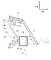
- FIG. 9 is an exploded cross-sectional view including the mounting member attached antenna device 128 taken along line AA of FIG. As shown in FIG. 9, the mounting member-equipped antenna device 128 has a mounting member 140 integrally formed of metal.
- the extending portion 146 is formed so as to extend away from the radiation plate 32 from the upper end of the fixed portion 44 in the vertical direction of the vehicle so as not to contact the back surface 24B.
- the extending portion 146 may be formed by extending from the lower end of the fixed portion 44 in the vehicle vertical direction or from between the upper and lower ends of the fixed portion 44 in the vehicle vertical direction in a direction away from the radiation plate 32 .
- the extending portion 146 is formed by extending obliquely upward and rearward from the vehicle 10 from the upper end of the fixed portion 44 in the vertical direction of the vehicle.
- the extending portion 146 is formed so as not to contact the first region 61 and the second region 62 .
- the installation angle of the windshield 12 is, for example, 23° with respect to the horizontal plane (XY plane) in a sedan type vehicle, and is, for example, 50° with respect to the horizontal plane in a wagon type light vehicle.
- the mounting angle of the rear glass 14 is, for example, 18 degrees with respect to the horizontal plane in a sedan type vehicle, and is, for example, 45 degrees with respect to a horizontal plane in a hatchback type vehicle.
- the antenna device 128 with mounting member can adjust the angle ⁇ 1 formed by the extending portion 146 and the radiation surface 32A within the range of 20° to 160° according to the mounting angle of the windshield 12 and the rear glass 14.
- the angle ⁇ 1 It can also be called the angle formed by the portion 146 and the fixed portion 44 .
- the angle ⁇ 2 of the direction in which the extending portion 146 extends with respect to the horizontal plane is adjusted, for example, within the range of ⁇ 30° to 70°. can.
- the extending portion 146 made of metal can be separated from the first region 61 and the second region 62. placed apart. Therefore, in the antenna device 128 with a mounting member, a change in the transmission/reception characteristics of the vertically polarized wave Q due to the metal extending portion 146 can be suppressed, a decrease in antenna gain can be suppressed, and a stable directivity can be ensured.
- ⁇ 1 may be in the range of 90° to 135°, or may be in the range of 45° to 90°.
- the extending direction of the extending portion 146 is in the range of -30° to 70° with respect to the horizontal plane, the extending portion 146 made of metal can be positioned between the first region 61 and the second region. 62. Therefore, in the antenna device 128 with a mounting member, a change in the transmission/reception characteristics of the vertically polarized wave Q due to the metal extending portion 146 can be suppressed, a decrease in antenna gain can be suppressed, and a stable directivity can be ensured.
- ⁇ 2 may be in the range of 0° to 45°, or may be in the range of -30° to 0°.
- the antenna device with a mounting member and the mounting structure of the antenna device of the third embodiment differ from the antenna device with the mounting member and the mounting structure of the antenna device of the above embodiments in that the configuration of the mounting member is different.
- the same terms or symbols will be used to describe the same or equivalent portions as those described in the above embodiment, and the description of the same configuration and effects as those in the above embodiment will be omitted.
- FIG. 10 is an exploded cross-sectional view including the mounting member attached antenna device 228 taken along line AA of FIG.
- a mounting member 240 of an antenna device 228 with a mounting member is integrally formed of metal and is composed of a mounting portion 42, a fixing portion 44, an extending portion 246, and a connecting portion 48. ing.
- the extending portion 246 is formed so as to extend away from the radiation plate 32 from the lower end of the fixing portion 44 in the vertical direction of the vehicle so as not to contact the back surface 24B.
- the extending portion 246 is formed by extending obliquely downward and rearward of the vehicle 10 from the lower end of the fixed portion 44 in the vertical direction of the vehicle.
- the extending portion 246 is formed so as not to contact the first region 61 and the second region 62 .
- the angle ⁇ 3 formed by the extending portion 246 and the radiation surface 32A can be adjusted within the range of 20° to 160°.
- the angle ⁇ 3 is It can also be called the angle formed by the portion 246 and the fixing portion 44 .
- the angle ⁇ 4 of the extending direction of the extending portion 246 with respect to the horizontal plane can be adjusted within a range of ⁇ 30° to 70° when the mounting member 240 is attached to the metal frame 16 .
- ⁇ 4 is a negative angle with respect to the horizontal plane when the direction in which the extending portion 246 separates from the fixing portion 44B is the depression angle direction, and when the direction in which the extending portion 246 separates from the fixing portion 44B is in the elevation direction. is an angle with a positive sign.
- the metal extending portion 246 of the mounting member-equipped antenna device 228 can It is arranged away from the first region 61 and the second region 62 . Therefore, in the antenna device 228 with the mounting member, the change in the transmission/reception characteristics of the vertically polarized wave Q due to the metal extending portion 346 can be suppressed, the decrease in the antenna gain can be suppressed, and the stable directivity can be ensured.
- ⁇ 3 may be in the range of 90° to 135°, or may be in the range of 45° to 90°.
- the extending direction of the extending portion 246 is in the range of -30° to 70° with respect to the horizontal plane, the extending portion 246 made of metal can be divided into the first region 61 and the second region. 62. Therefore, in the antenna device 228 with a mounting member, changes in the transmission/reception characteristics of the vertically polarized wave Q due to the metal extending portion 246 can be suppressed, a decrease in antenna gain can be suppressed, and stable directivity can be ensured.
- ⁇ 4 may be in the range of 0° to 45°, or may be in the range of -30° to 0°.
- the antenna device with a mounting member and the mounting structure of the antenna device of the fourth embodiment differ from the antenna device with the mounting member and the mounting structure of the antenna device of the above-described embodiments in that the configuration of the antenna is different.
- FIG. 11 is a perspective view of the antenna 130.
- the antenna 130 is a patch antenna (microstrip antenna) including a radiation plate (radiation conductor) 132, a dielectric base 134, a ground conductor plate 135, and a connection conductor 136. be.
- the dielectric base material 134 is a dielectric layer containing a dielectric as a main component.
- a radiation plate 132 is provided on the surface (first main surface) of the dielectric base material 134 . Radiating plate 132 functions as a radiating element of antenna 130 .
- a ground conductor plate 135 is provided on the back surface (second main surface) of the dielectric base material 134 . The ground conductor plate 135 is connected to the covered ground wire of the coaxial cable 50 .
- connection conductor 136 connects the feeding point P2 of the radiation plate 132 and the signal line (core line) of the coaxial cable 50 . Note that the connection conductor 136 does not contact the ground conductor plate 135 .
- a front surface of the radiation plate 132 in the vehicle front-rear direction constitutes a radiation surface 132A.
- the radiation surface 132A radiates a vertically polarized wave Q of 5.8 GHz band or 5.9 GHz band used in vehicle-to-vehicle communication, road-to-vehicle communication, and the like.
- the antenna 130 includes a ground conductor plate 135 with a dielectric substrate 134 interposed therebetween on the side opposite to the side on which the radiation surface 132A is arranged with respect to the radiation plate 132 .
- the feeding point P2 of the antenna 130 is located on the first straight line 71 at a position different from the center of gravity P1 of the radiation plate 132.
- the width W of the fixing portion 44 in the extending direction of the first straight line 71 is formed to be narrower than the width LP of the ground conductor plate 135 in the extending direction of the first straight line 71 .
- FIG. 12 is a plan view showing the antenna device with the mounting member as seen from the thickness direction of the radiation plate 132 on the side opposite to the radiation surface 132A side.
- the fixing portion 44 is arranged such that the longitudinal axis 44 C of the fixing portion 44 overlaps the second straight line 72 . Accordingly, in the extending direction of the first straight line 71, the first region 61 and the second region 62 where the metal fixing portion 44 is not arranged have substantially the same size.
- the width W of the fixing portion 44 in the extending direction of the first straight line 71 and the width LP of the ground conductor plate 135 in the extending direction of the first straight line 71 preferably satisfy the following formula (2a), and satisfy formula (2b). Then, it is preferable, and it is more preferable to satisfy the formula (2c). If W/L P is less than 0.01, the fixing strength between the fixing portion 44 and the housing portion 20 may be weak and unstable. Moreover, when W/L P exceeds 0.75, the antenna gain of the antenna 130 may decrease.
- the antenna 130 may further include a parasitic conductor plate (not shown).
- a non-feeding conductor plate is a conductor that is not connected to (the conductor of the ground potential of) a power supply line, a ground line, or the like of a transmission line.
- the parasitic conductor plate may be arranged, for example, on the main surface of the dielectric substrate 134 on the side where the radiating plate 132 is arranged so as not to overlap the radiating plate 132 . Also, one or two parasitic conductor plates may be provided.
- the antenna 130 When two parasitic conductive plates are provided, one on each side of the first straight line 71 may be arranged in a shape symmetrical with respect to the first straight line 71 .
- the parasitic conductor plate has a quadrangular (for example, rectangular) outer edge extending in the vibration direction D of the vertically polarized wave Q, the antenna 130 extends in the LH-FR-RH direction (see FIG. 8). Good directivity is likely to be obtained in the angle range of the horizontal plane (angle range of 180°).
- the antenna device with a mounting member according to the fourth embodiment can be firmly attached to the vehicle body with high rigidity. In addition, it is possible to suppress a decrease in antenna gain, thereby ensuring stable directivity.
- the antenna device with a mounting member and the antenna device have been described above based on the above embodiments. However, the specific configuration is not limited to these embodiments, and design changes and the like are permitted as long as they do not depart from the gist of the inventions according to the claims.
- FIG. 13 is an exploded cross-sectional view including the mounting member attached antenna device 328 taken along BB in FIG.
- the mounting member-equipped antenna device 328 may be mounted on the rear glass 14 near the interior side of the vehicle.
- the extending portion 346 may be formed, for example, by extending from the lower end of the fixed portion 44 in the vehicle up-down direction (vertical direction) toward the front of the vehicle (inside the vehicle compartment).
- the connecting portion 48 may be formed in a substantially L shape in a cross section along the YZ plane.
- the antenna device 328 with mounting member 328 may be mounted near the top of the windshield 12 .
- one antenna device with a mounting member is mounted near the windshield 12 of the vehicle 10 .
- one or more antenna devices with mounting members may be mounted near the windshield 12 and near the rear glass 14 of the vehicle 10, or may be mounted at other locations.
- an example in which the accommodating portion 20 is provided with the protruding portion 25A is shown.
- the accommodation portion may not have a protrusion.
- an attachment portion for attaching the fixing portion 44 to the housing portion 20 may be provided inside the outer edge of the rear surface 24B of the housing portion 20 .
- the housing portion 20 houses the entire antenna 30 .
- the accommodation portion may accommodate at least part of the antenna.
- the mounting member 40 is formed in a substantially U shape by the mounting portion 42, the extending portion 46, and the connecting portion 48 in the YZ plane cross section.
- the attachment member may be formed in a crank shape by the attachment portion, the extension portion, and the connection portion in the cross section along the YZ plane, or may have another shape.
- the antennas 30 and 130 are antennas for transmitting and receiving vertically polarized waves Q in the 5.8 GHz band or 5.9 GHz band used in vehicle-to-vehicle communication and road-to-vehicle communication.
- the antenna may be an antenna that transmits and receives vertically polarized waves in other frequency bands.
- the antenna may be an antenna that transmits and receives horizontally polarized waves (an example of linearly polarized waves).
- the mounting member 40 is made of metal and is integrally formed. However, it is sufficient that at least the fixing portion 44 of the mounting member is made of metal. Also, the mounting member may be partially formed separately.
- the number of attachment portions for attaching the fixing portion 44 to the housing portion 20 may be one or three or more.
- the antennas 30 and 130 are V2X antennas.
- various antennas such as an antenna for receiving broadcast radio waves, an ITS antenna, and a 1.2 GHz band antenna can be applied.
- the disclosure of Japanese Patent Application No. 2021-202862 filed on December 14, 2021 is incorporated herein by reference in its entirety.
Landscapes
- Engineering & Computer Science (AREA)
- Remote Sensing (AREA)
- Details Of Aerials (AREA)
- Support Of Aerials (AREA)
Priority Applications (2)
| Application Number | Priority Date | Filing Date | Title |
|---|---|---|---|
| JP2023567763A JPWO2023112866A1 (enExample) | 2021-12-14 | 2022-12-09 | |
| US18/739,467 US20240332811A1 (en) | 2021-12-14 | 2024-06-11 | Antenna device with attachment member and attachment structure for antenna device |
Applications Claiming Priority (2)
| Application Number | Priority Date | Filing Date | Title |
|---|---|---|---|
| JP2021202862 | 2021-12-14 | ||
| JP2021-202862 | 2021-12-14 |
Related Child Applications (1)
| Application Number | Title | Priority Date | Filing Date |
|---|---|---|---|
| US18/739,467 Continuation US20240332811A1 (en) | 2021-12-14 | 2024-06-11 | Antenna device with attachment member and attachment structure for antenna device |
Publications (1)
| Publication Number | Publication Date |
|---|---|
| WO2023112866A1 true WO2023112866A1 (ja) | 2023-06-22 |
Family
ID=86774713
Family Applications (1)
| Application Number | Title | Priority Date | Filing Date |
|---|---|---|---|
| PCT/JP2022/045566 Ceased WO2023112866A1 (ja) | 2021-12-14 | 2022-12-09 | 取付部材付きアンテナ装置及びアンテナ装置の取付構造 |
Country Status (3)
| Country | Link |
|---|---|
| US (1) | US20240332811A1 (enExample) |
| JP (1) | JPWO2023112866A1 (enExample) |
| WO (1) | WO2023112866A1 (enExample) |
Citations (3)
| Publication number | Priority date | Publication date | Assignee | Title |
|---|---|---|---|---|
| JP2001203520A (ja) * | 2000-01-24 | 2001-07-27 | Denso Corp | 車載通信装置用のアンテナユニット |
| WO2018147258A1 (ja) * | 2017-02-10 | 2018-08-16 | 株式会社ヨコオ | アンテナ取付装置 |
| JP2019075644A (ja) * | 2017-10-13 | 2019-05-16 | 株式会社ヨコオ | パッチアンテナおよび車載用アンテナ装置 |
-
2022
- 2022-12-09 JP JP2023567763A patent/JPWO2023112866A1/ja active Pending
- 2022-12-09 WO PCT/JP2022/045566 patent/WO2023112866A1/ja not_active Ceased
-
2024
- 2024-06-11 US US18/739,467 patent/US20240332811A1/en active Pending
Patent Citations (3)
| Publication number | Priority date | Publication date | Assignee | Title |
|---|---|---|---|---|
| JP2001203520A (ja) * | 2000-01-24 | 2001-07-27 | Denso Corp | 車載通信装置用のアンテナユニット |
| WO2018147258A1 (ja) * | 2017-02-10 | 2018-08-16 | 株式会社ヨコオ | アンテナ取付装置 |
| JP2019075644A (ja) * | 2017-10-13 | 2019-05-16 | 株式会社ヨコオ | パッチアンテナおよび車載用アンテナ装置 |
Also Published As
| Publication number | Publication date |
|---|---|
| JPWO2023112866A1 (enExample) | 2023-06-22 |
| US20240332811A1 (en) | 2024-10-03 |
Similar Documents
| Publication | Publication Date | Title |
|---|---|---|
| US11069961B2 (en) | Antenna device having an antenna element coupled at a notch of a ground conductor thereof | |
| US11476565B2 (en) | Patch antenna and antenna device for vehicle | |
| CN108475851B (zh) | 具有天线装置的机动车 | |
| CN105026213B (zh) | 窗框架 | |
| JP2019068124A (ja) | パッチアンテナ及びアンテナ装置 | |
| JPWO2019124518A1 (ja) | 車載用アンテナ装置 | |
| CN107978844A (zh) | 车辆用天线以及带天线的窗玻璃 | |
| US12463330B2 (en) | Antenna device for a vehicle | |
| JP2017168938A (ja) | 車載用アンテナ装置 | |
| US11962076B2 (en) | Antenna device | |
| WO2023112866A1 (ja) | 取付部材付きアンテナ装置及びアンテナ装置の取付構造 | |
| CN113745811A (zh) | 天线装置 | |
| CN218160806U (zh) | 贴片天线以及天线装置 | |
| JP6035170B2 (ja) | 窓フレーム | |
| JP2008135931A (ja) | Etc用車載アンテナ及びアンテナの指向性設定方法 | |
| US20240347899A1 (en) | Antenna device and vehicle antenna device | |
| JP6756868B2 (ja) | アンテナ装置 | |
| JP7015359B2 (ja) | アンテナ装置 | |
| US20240405404A1 (en) | Connection terminal and antenna device | |
| JP2015195574A (ja) | 自動車用ガラスアンテナ | |
| WO2023100908A1 (ja) | アンテナ装置及び車両用アンテナ装置 | |
| JP2010068473A (ja) | 統合アンテナ、及び車載端末装置 | |
| CN118435462A (zh) | 贴片天线以及天线装置 | |
| WO2024176729A1 (ja) | アンテナ及びアンテナの製造方法 | |
| WO2024116430A1 (ja) | アンテナ装置 |
Legal Events
| Date | Code | Title | Description |
|---|---|---|---|
| 121 | Ep: the epo has been informed by wipo that ep was designated in this application |
Ref document number: 22907393 Country of ref document: EP Kind code of ref document: A1 |
|
| WWE | Wipo information: entry into national phase |
Ref document number: 2023567763 Country of ref document: JP |
|
| NENP | Non-entry into the national phase |
Ref country code: DE |
|
| 122 | Ep: pct application non-entry in european phase |
Ref document number: 22907393 Country of ref document: EP Kind code of ref document: A1 |