WO2023112846A1 - 炭化水素系化合物の製造装置及び製造方法 - Google Patents
炭化水素系化合物の製造装置及び製造方法 Download PDFInfo
- Publication number
- WO2023112846A1 WO2023112846A1 PCT/JP2022/045409 JP2022045409W WO2023112846A1 WO 2023112846 A1 WO2023112846 A1 WO 2023112846A1 JP 2022045409 W JP2022045409 W JP 2022045409W WO 2023112846 A1 WO2023112846 A1 WO 2023112846A1
- Authority
- WO
- WIPO (PCT)
- Prior art keywords
- hydrocarbon
- based compound
- cathode
- producing
- gas
- Prior art date
- Legal status (The legal status is an assumption and is not a legal conclusion. Google has not performed a legal analysis and makes no representation as to the accuracy of the status listed.)
- Ceased
Links
Images

Classifications
-
- C—CHEMISTRY; METALLURGY
- C07—ORGANIC CHEMISTRY
- C07C—ACYCLIC OR CARBOCYCLIC COMPOUNDS
- C07C1/00—Preparation of hydrocarbons from one or more compounds, none of them being a hydrocarbon
- C07C1/02—Preparation of hydrocarbons from one or more compounds, none of them being a hydrocarbon from oxides of a carbon
-
- C—CHEMISTRY; METALLURGY
- C07—ORGANIC CHEMISTRY
- C07C—ACYCLIC OR CARBOCYCLIC COMPOUNDS
- C07C9/00—Aliphatic saturated hydrocarbons
- C07C9/02—Aliphatic saturated hydrocarbons with one to four carbon atoms
- C07C9/04—Methane
-
- C—CHEMISTRY; METALLURGY
- C25—ELECTROLYTIC OR ELECTROPHORETIC PROCESSES; APPARATUS THEREFOR
- C25B—ELECTROLYTIC OR ELECTROPHORETIC PROCESSES FOR THE PRODUCTION OF COMPOUNDS OR NON-METALS; APPARATUS THEREFOR
- C25B11/00—Electrodes; Manufacture thereof not otherwise provided for
- C25B11/02—Electrodes; Manufacture thereof not otherwise provided for characterised by shape or form
- C25B11/03—Electrodes; Manufacture thereof not otherwise provided for characterised by shape or form perforated or foraminous
- C25B11/031—Porous electrodes
- C25B11/032—Gas diffusion electrodes
-
- C—CHEMISTRY; METALLURGY
- C25—ELECTROLYTIC OR ELECTROPHORETIC PROCESSES; APPARATUS THEREFOR
- C25B—ELECTROLYTIC OR ELECTROPHORETIC PROCESSES FOR THE PRODUCTION OF COMPOUNDS OR NON-METALS; APPARATUS THEREFOR
- C25B11/00—Electrodes; Manufacture thereof not otherwise provided for
- C25B11/04—Electrodes; Manufacture thereof not otherwise provided for characterised by the material
- C25B11/051—Electrodes formed of electrocatalysts on a substrate or carrier
- C25B11/052—Electrodes comprising one or more electrocatalytic coatings on a substrate
-
- C—CHEMISTRY; METALLURGY
- C25—ELECTROLYTIC OR ELECTROPHORETIC PROCESSES; APPARATUS THEREFOR
- C25B—ELECTROLYTIC OR ELECTROPHORETIC PROCESSES FOR THE PRODUCTION OF COMPOUNDS OR NON-METALS; APPARATUS THEREFOR
- C25B13/00—Diaphragms; Spacing elements
- C25B13/04—Diaphragms; Spacing elements characterised by the material
- C25B13/05—Diaphragms; Spacing elements characterised by the material based on inorganic materials
- C25B13/07—Diaphragms; Spacing elements characterised by the material based on inorganic materials based on ceramics
-
- C—CHEMISTRY; METALLURGY
- C25—ELECTROLYTIC OR ELECTROPHORETIC PROCESSES; APPARATUS THEREFOR
- C25B—ELECTROLYTIC OR ELECTROPHORETIC PROCESSES FOR THE PRODUCTION OF COMPOUNDS OR NON-METALS; APPARATUS THEREFOR
- C25B3/00—Electrolytic production of organic compounds
- C25B3/01—Products
- C25B3/03—Acyclic or carbocyclic hydrocarbons
-
- C—CHEMISTRY; METALLURGY
- C25—ELECTROLYTIC OR ELECTROPHORETIC PROCESSES; APPARATUS THEREFOR
- C25B—ELECTROLYTIC OR ELECTROPHORETIC PROCESSES FOR THE PRODUCTION OF COMPOUNDS OR NON-METALS; APPARATUS THEREFOR
- C25B3/00—Electrolytic production of organic compounds
- C25B3/20—Processes
- C25B3/25—Reduction
- C25B3/26—Reduction of carbon dioxide
-
- C—CHEMISTRY; METALLURGY
- C25—ELECTROLYTIC OR ELECTROPHORETIC PROCESSES; APPARATUS THEREFOR
- C25B—ELECTROLYTIC OR ELECTROPHORETIC PROCESSES FOR THE PRODUCTION OF COMPOUNDS OR NON-METALS; APPARATUS THEREFOR
- C25B9/00—Cells or assemblies of cells; Constructional parts of cells; Assemblies of constructional parts, e.g. electrode-diaphragm assemblies; Process-related cell features
-
- C—CHEMISTRY; METALLURGY
- C25—ELECTROLYTIC OR ELECTROPHORETIC PROCESSES; APPARATUS THEREFOR
- C25B—ELECTROLYTIC OR ELECTROPHORETIC PROCESSES FOR THE PRODUCTION OF COMPOUNDS OR NON-METALS; APPARATUS THEREFOR
- C25B9/00—Cells or assemblies of cells; Constructional parts of cells; Assemblies of constructional parts, e.g. electrode-diaphragm assemblies; Process-related cell features
- C25B9/17—Cells comprising dimensionally-stable non-movable electrodes; Assemblies of constructional parts thereof
- C25B9/19—Cells comprising dimensionally-stable non-movable electrodes; Assemblies of constructional parts thereof with diaphragms
- C25B9/23—Cells comprising dimensionally-stable non-movable electrodes; Assemblies of constructional parts thereof with diaphragms comprising ion-exchange membranes in or on which electrode material is embedded
Definitions
- the present invention relates to an apparatus and method for producing a hydrocarbon compound that synthesizes a hydrocarbon compound from H 2 O and CO 2 by energization, and in particular, to a production reaction of a hydrocarbon compound by ensuring gas diffusion of the produced gas.
- the present invention relates to an apparatus and method for producing a hydrocarbon-based compound, which can improve the efficiency of the production of the hydrocarbon-based compound and can maintain the equilibrium of the production reaction of the hydrocarbon-based compound in an advantageous state.
- Patent Document 1 a system using a methanation reaction using CO 2 , which is a cause of global warming, as a raw material has been proposed (for example, Patent Document 1).
- a water electrolysis system PCEC
- proton conductive ceramics for example, Non-Patent Document 1
- methane can be produced by simultaneously electrolyzing CO 2 on the cathode side.
- the efficiency of the production reaction of hydrocarbon compounds is improved by ensuring the gas diffusibility of the raw material CO 2 to the cathode and also the gas diffusivity of the produced gas. It is an object of the present invention to provide a hydrocarbon-based compound production apparatus capable of improving the reaction efficiency and maintaining the equilibrium of the hydrocarbon-based compound production reaction in a state favorable to the production of the hydrocarbon-based compound.
- the present invention was invented to solve the problems in the prior art as described above, and the apparatus and method for producing a hydrocarbon compound of the present invention include those configured as follows. .
- a hydrocarbon-based compound manufacturing apparatus for synthesizing a hydrocarbon-based compound from H 2 O and CO 2 by energization, an electrolytic cell having a fuel synthesis section including a cathode, a proton generation section including an anode, and an electrolyte membrane disposed between the cathode and the anode; a gas diffusion layer provided on a side of the cathode opposite to the side having the electrolyte membrane;
- An apparatus for producing a hydrocarbon-based compound comprising: a generated gas discharge section for discharging a generated gas generated in the fuel synthesizing section from the fuel synthesizing section.
- the diffusibility of CO 2 to the cathode is ensured, and the efficiency of the hydrocarbon-based compound production reaction is increased. can be done.
- the gas diffusion layer can also ensure the diffusibility of the generated gas, the generated gas can be easily discharged from the generated gas discharge part, and the equilibrium of the hydrocarbon compound generation reaction can be maintained. can be kept in favor of
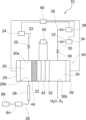
- FIG. 1 is a schematic diagram for explaining the configuration of a hydrocarbon-based compound production apparatus according to the present embodiment.
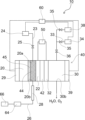
- FIG. 2 is a schematic diagram showing a modification of the hydrocarbon-based compound production apparatus of FIG.
- FIG. 3 is a schematic diagram for explaining the configuration of a hydrocarbon-based compound production apparatus according to another embodiment.
- FIG. 1 is a schematic diagram for explaining the configuration of a hydrocarbon-based compound production apparatus according to the present embodiment.
- hydrocarbon-based compound an example of producing methane (CH 4 ) as a fuel (also referred to as a “hydrocarbon-based compound” in this specification) is described.
- hydrocarbons including alcohols such as methanol and ethanol, aldehydes such as formaldehyde and acetaldehyde, carboxylic acids such as formic acid and acetic acid, and ethers such as dimethyl ether. It can also be applied to devices.
- the type of hydrocarbon compound to be produced can be selected, for example, by selecting the material of the cathode or adjusting the amounts of CO 2 and H 2 O supplied to the production apparatus. Hydrocarbon compounds can also be produced simultaneously.
- the hydrocarbon-based compound manufacturing apparatus 10 of the present embodiment includes a fuel synthesizing section 20 including a cathode 22, a proton generating section 30 including an anode 32, and between the cathode 22 and the anode 32 an electrolytic cell 40 having an electrolyte membrane 42 disposed thereon.
- the anode 32 and the cathode 22 are connected to a power source 50 and are configured such that current flows from the cathode 22 to the power source 50 and current flows from the power source 50 to the anode 32 .
- the electrolyte membrane 42 is not particularly limited as long as it is a membrane that has the property of allowing ions to pass through mainly as charge carriers, and has the property of preventing an electrical short circuit between the anode 32 and the cathode 22.
- Proton-conducting ceramics are preferably used as such a proton-conducting material.
- An H 2 O supply unit 34 for supplying H 2 O to the proton generation unit 30 is connected to the proton generation unit 30, while a cathode containing CO 2 in the fuel synthesis unit 20 is connected to the fuel synthesis unit 20.
- a cathode gas supply unit 24 for supplying gas is connected.
- the cathode gas supplied from the cathode gas supply unit 24 is not particularly limited as long as it contains at least CO2 . It may be a mixed gas with active gas, a mixed gas with NOx or CO, or air.
- Pressure regulating valves 35 and 25 are provided on the H 2 O supply path 33 from the H 2 O supply section 34 to the proton generation section 30 and on the cathode gas supply path 23 from the cathode gas supply section 24 to the fuel synthesis section 20, respectively. is provided.
- a check valve 36 is provided on the H 2 O supply path 33 from the H 2 O supply unit 34 to the proton generation unit 30 , and the H 2 O This prevents H 2 O from flowing back to the 2 O supply section 34 .
- the hydrocarbon-based compound manufacturing apparatus 10 of the present embodiment also includes a carrier gas supply unit 38 that supplies a carrier gas for transporting H 2 O supplied from the H 2 O supply unit 34 .
- a carrier gas supply unit 38 that supplies a carrier gas for transporting H 2 O supplied from the H 2 O supply unit 34 .
- a gas diffusion layer 44 is provided on the side of the cathode 22 opposite to the side having the electrolyte membrane 42 .
- the cathode 22 and the gas diffusion layer 44 are arranged in contact with each other, but they may be arranged apart, that is, a gap may be provided between the cathode 22 and the gas diffusion layer 44. .
- the gas diffusion layer 44 for example, a known gas diffusion layer may be used as long as it does not have electrical conductivity such as ceramics or metal oxide.
- electrical conductivity such as ceramics or metal oxide.
- silicate minerals such as cordierite, zeolite and diatomaceous earth, and metal oxides such as ceria, zirconia, alumina and titania can be used.
- the gas diffusion layer 44 has a porous structure including through-holes, and in particular, the porosity of the gas diffusion layer 44 is preferably 50% or more and 98% or less, and more preferably 60% or more and 90% or less. is more preferably 65% or more and 80% or less.
- a gas diffusion layer 44 contains ceramics.
- the thickness of the gas diffusion layer 44 is preferably 0.5 ⁇ m or more, more preferably 50 ⁇ m or more, and even more preferably 100 ⁇ m or more.
- the upper limit of the thickness of the gas diffusion layer 44 is not particularly limited, it is preferably 10 mm or less, more preferably 5 mm or less, and 1 mm or less from the viewpoint of device configuration and operability. is more preferred.
- the gas diffusion layer 44 is preferably in the form of a non-woven fabric. For example, it is possible to use a non-woven fabric obtained by processing oxides such as ceramic nanofibers.
- the cathode gas supplied from the cathode gas supply section 24 to the fuel synthesizing section 20 through the cathode gas supply path 23 is directly introduced into the gas diffusion layer 44 from the inlet 20a of the fuel synthesizing section 20.
- the cathode gas is supplied to the cathode 22 through the gas diffusion layer 44. For example, as shown in FIG. It doesn't matter if you do it.
- the cathode gas diffuses in the gas diffusion layer 44 and contacts the entire cathode surface. can be done. Therefore, the protons supplied to the fuel synthesizing section 20 via the electrolyte membrane 42 can be used for the reaction with high efficiency, so that the efficiency of the hydrocarbon-based compound generation reaction at the cathode 22 can be improved.
- the produced gas containing the hydrocarbon compound produced in the fuel synthesizing section 20 is discharged from the outlet 20b of the fuel synthesizing section 20 .
- the generated gas discharged from the outlet 20b of the fuel synthesizing unit 20 may contain, in addition to hydrocarbon compounds, CO 2 , CO, H 2 , H 2 O, etc. that have not undergone a generation reaction. .
- a product gas separation unit 64 that separates only methane from the product gas in the fuel synthesis unit 20 is provided in the outlet pipe 26 that is a product gas discharge unit connected to the outlet 20 b of the fuel synthesis unit 20 .
- the methane separated by the generated gas separation section 64 is recovered and stored in the CH 4 recovery section 66 .
- the generated gas separation unit 64 is configured to separate only methane, but the generated gas other than methane after separation can be discharged as it is. It is also possible to separate each component and reuse CO 2 and H 2 O contained in the generated gas.
- the generated gas is directly discharged from the gas diffusion layer 44 to the outlet pipe 26.
- the generated gas may be discharged from a position where the gas diffusion layer 44 does not exist.
- the generated gas by configuring the generated gas to be discharged to the outlet side pipe 26 via the gas diffusion layer 44, the diffusibility of the generated gas can be ensured, and the generated gas is discharged to the outlet side pipe 26. easier to be Therefore, the generated gas remaining in the fuel synthesizing section 20 can be reduced, and the equilibrium of the hydrocarbon-based compound generation reaction can be maintained in a state favorable to the generation of the hydrocarbon-based compound.
- the outlet pipe 26 is provided with cooling means 28 for cooling the produced gas flowing through the pipe.
- a cooling means 28 is provided downstream of the outlet 20b of the fuel synthesizing section 20 and upstream of the generated gas separating section 64, and the gas discharged from the fuel synthesizing section 20 is Water and methane are separated by cooling the product gas by cooling means 28 .
- the cooling means 28 is not particularly limited as long as it can cool the generated gas in the pipe through the outlet side pipe 26, and may be water-cooled or air-cooled.
- the fuel synthesizing section 20 and the proton generating section 30 are provided with a cathode gas heating section 29 and an H 2 O heating section 39, respectively.
- CO 2 and H 2 O are electrolyzed in the fuel synthesizing section 20 and the proton generating section 30, respectively, CO 2 and H 2 O are produced by heating with the cathode gas heating section 29 and the H 2 O heating section 39. electrolysis efficiency is improved.
- a cathode gas preheating unit for heating the cathode gas supplied from the cathode gas supply unit 24 to the fuel synthesizing unit 20, and a proton generating unit 30 from the H 2 O supply unit 34
- An H 2 O preheating section for heating the supplied H 2 O can also be provided, whereby the H 2 O can be supplied as low temperature steam.
- the discharge part 30b may be provided at any position as long as the gas in the proton generation part 30 can be discharged. Note that H 2 O that has not been electrolyzed is also discharged from the discharge part. Also, although not shown, for example, a path for the discharged H 2 O to flow from the discharge portion 30b to the H 2 O supply portion 34 may be provided and circulated, so that H 2 O can be reused.
- the hydrocarbon-based compound manufacturing apparatus 10 of the present embodiment includes a cathode gas supply unit 24, an H 2 O supply unit 34, a carrier gas supply unit 38, a cathode gas heating unit 29, an H 2 O heating unit 39, and an electric It has a control unit 60 that is physically connected.
- the controller 60 controls the amount of cathode gas supplied from the cathode gas supply unit 24, the amount of H 2 O supplied from the H 2 O supply unit 34, the amount of carrier gas supplied from the carrier gas supply unit 38, and the cathode gas heater. 29 and the H 2 O heating unit 39 are controlled.
- FIG. 3 is a schematic diagram for explaining the configuration of a hydrocarbon-based compound production apparatus according to another embodiment.
- the hydrocarbon compound production apparatus 10 shown in FIG. 3 basically has the same configuration as the hydrocarbon compound production apparatus 10 shown in FIGS. , and detailed description thereof is omitted.
- the hydrocarbon-based compound manufacturing apparatus 10 of the present embodiment includes a hydrogenation catalyst layer 45 on the surface of the gas diffusion layer 44 on the side not facing the cathode 22 .
- a hydrogenation catalyst layer 45 for example, transition metals such as Ni, Ru, Cu, Zn, Mn and Co, alkaline earth metals such as Mg and Ca, Na and Al can be used.
- the hydrogenation catalyst layer 45 can use these metals singly or as a composite oxide containing two or more elements.
- the hydrogenation catalyst layer 45 can perform a hydrogenation reaction of unreacted CO 2 contained in the cathode gas, that is, a reaction to produce a hydrocarbon-based compound. Since the activation energy required for the reaction can be lowered, the reaction efficiency of the reaction for producing the hydrocarbon-based compound can be further improved.
- the hydrophilicity/hydrophobicity of the gas diffusion layer 44 can be appropriately selected according to the device configuration and the hydrocarbon compound to be produced.
- the surface of the gas diffusion layer 44 on the cathode 22 side hydrophilic and the surface of the gas diffusion layer 44 on the hydrogenation catalyst layer 45 side hydrophobic, reaction inhibitors on the cathode 22 side It is possible to suppress the presence of water, and to prevent contact between unreacted cathode gas and water on the catalyst layer side, so that the reaction efficiency of the hydrocarbon-based compound generation reaction can be further improved. can.
- Manufacturing device 20 Fuel synthesizing unit 20a Fuel synthesizing unit inlet 20b Fuel synthesizing unit outlet 22 Cathode 23 Cathode gas supply path 24 Cathode gas supply unit 25 Pressure regulating valve 26 Outlet pipe 28 Cooling means 29 Cathode gas heating unit 30 Proton generating unit 30b Discharge part (proton generator exit) 32 anode 33 H 2 O supply path 34 H 2 O supply unit 35 pressure control valve 36 check valve 38 carrier gas supply unit 39 H 2 O heating unit 40 electrolytic cell 42 electrolyte membrane 44 gas diffusion layer 45 hydrogenation catalyst layer 50 power supply 60 control unit 64 generated gas separation unit 66 CH 4 recovery unit
Landscapes
- Chemical & Material Sciences (AREA)
- Organic Chemistry (AREA)
- Engineering & Computer Science (AREA)
- Chemical Kinetics & Catalysis (AREA)
- Electrochemistry (AREA)
- Materials Engineering (AREA)
- Metallurgy (AREA)
- Oil, Petroleum & Natural Gas (AREA)
- General Chemical & Material Sciences (AREA)
- Ceramic Engineering (AREA)
- Inorganic Chemistry (AREA)
- Electrolytic Production Of Non-Metals, Compounds, Apparatuses Therefor (AREA)
Abstract
[課題]原料であるCO2のカソードへのガス拡散性を確保するとともに、生成ガスのガス拡散性も確保することで、炭化水素系化合物の生成反応の効率を向上させるとともに、炭化水素系化合物の生成反応の平衡を、炭化水素系化合物の生成に有利な状態に保つことができる炭化水素系化合物の製造装置を提供する。 [解決手段]通電によりH2O及びCO2から炭化水素系化合物を合成する炭化水素系化合物の製造装置であって、カソードを含む燃料合成部と、アノードを含むプロトン発生部と、カソード及びアノード間に配置された電解質膜とを有する電解槽と、カソードの電解質膜を有する側とは反対側に設けられたガス拡散層と、燃料合成部において生成された生成ガスを、燃料合成部から排出する生成ガス排出部とを備える。
Description
本発明は、通電によりH2O及びCO2から炭化水素系化合物を合成する炭化水素系化合物の製造装置及び製造方法に関し、特に、生成ガスのガス拡散性を確保し炭化水素系化合物の生成反応の効率を向上させるとともに、炭化水素系化合物の生成反応の平衡を有利な状態に保つことができる炭化水素系化合物の製造装置及び製造方法に関する。
近年、環境問題への意識の高まりから、地球温暖化の原因であるCO2を原料としたメタネーション反応を利用したシステムが提案されている(例えば、特許文献1)。このようなメタネーションシステムのうち、プロトン伝導性セラミックスを用いた水電解システム(PCEC)(例えば、非特許文献1)では、アノード側でH2Oを電気分解することで、プロトン(H+)が電解質中を移動し、カソード側にH2が発生する。このとき、同時にカソード側でCO2を電気分解することで、メタンの生成が可能である。
李 坤朋、荒木 拓人、森 昌史、「プロトン伝導体/酸化物イオン伝導体形水蒸気電解による水素製造システムの効率検討」、燃料電池、一般社団法人燃料電池開発情報センター、令和2年7月30日、第20巻、第1号、p.76-83
このような、メタンの生成反応では、カソード側に副生成物として水が生成される。メタンの生成反応は平衡反応であるため、水の存在が反応の阻害となることが知られている。
また、生成されたメタンがカソード近辺に残留していると、同様に、残留するメタンの存在が反応の阻害となってしまう。
また、生成されたメタンがカソード近辺に残留していると、同様に、残留するメタンの存在が反応の阻害となってしまう。
本発明では、このような現状に鑑み、原料であるCO2のカソードへのガス拡散性を確保するとともに、生成ガスのガス拡散性も確保することで、炭化水素系化合物の生成反応の効率を向上させるとともに、炭化水素系化合物の生成反応の平衡を、炭化水素系化合物の生成に有利な状態に保つことができる炭化水素系化合物の製造装置を提供することを目的とする。
本発明は、上述するような従来技術における課題を解決するために発明されたものであって、本発明の炭化水素系化合物の製造装置及び製造方法は、以下のように構成されたものを含む。
[1] 通電によりH2O及びCO2から炭化水素系化合物を合成する炭化水素系化合物の製造装置であって、
カソードを含む燃料合成部と、アノードを含むプロトン発生部と、カソード及びアノード間に配置された電解質膜と、を有する電解槽と、
前記カソードの前記電解質膜を有する側とは反対側に設けられたガス拡散層と、
前記燃料合成部において生成された生成ガスを、前記燃料合成部から排出する生成ガス排出部と、を備える、炭化水素系化合物の製造装置。
カソードを含む燃料合成部と、アノードを含むプロトン発生部と、カソード及びアノード間に配置された電解質膜と、を有する電解槽と、
前記カソードの前記電解質膜を有する側とは反対側に設けられたガス拡散層と、
前記燃料合成部において生成された生成ガスを、前記燃料合成部から排出する生成ガス排出部と、を備える、炭化水素系化合物の製造装置。
[2] 前記ガス拡散層を、前記カソードと接して配置される、[1]に記載の炭化水素系化合物の製造装置。
[3] 前記ガス拡散層が、貫通孔を含む多孔質構造を有する、[1]または[2]に記載の炭化水素系化合物の製造装置。
[4] 前記ガス拡散層の空隙率が、50%以上98%以下である、[1]から[3]のいずれかに記載の炭化水素系化合物の製造装置。
[5] 前記ガス拡散層が、セラミックスを含む、[1]から[4]のいずれかに記載の炭化水素系化合物の製造装置。
[6] 前記ガス拡散層の厚みが、0.5μm以上である、[1]から[5]のいずれかに記載の炭化水素系化合物の製造装置。
[7] 前記ガス拡散層が、前記カソードと対向していない側の表面にCO2を水素化する水素化触媒層を備える、[1]から[6]のいずれかに記載の炭化水素系化合物の製造装置。
[8] 前記電解質膜が、プロトン伝導性材料を含む、[1]から[7]のいずれかに記載の炭化水素系化合物の製造装置。
[9] 前記プロトン伝導性材料が、プロトン伝導性セラミックスである、[8]に記載の炭化水素系化合物の製造装置。
[10] 前記生成ガス排出部が、冷却手段を有する、[1]から[9]のいずれかに記載の炭化水素系化合物の製造装置。
[11] [1]から[10]のいずれかの炭化水素系化合物の製造装置を用いて、炭化水素系化合物の製造を行う炭化水素系化合物の製造方法であって、
少なくともCO2を含むカソードガスを前記燃料合成部に供給し、かつ、H2Oを前記プロトン発生部に供給するとともに、
前記カソードと前記アノードとを通電する、炭化水素系化合物の製造方法。
少なくともCO2を含むカソードガスを前記燃料合成部に供給し、かつ、H2Oを前記プロトン発生部に供給するとともに、
前記カソードと前記アノードとを通電する、炭化水素系化合物の製造方法。
本発明によれば、カソードの電解質膜を有する側とは反対側にガス拡散層を備えることによって、カソードへのCO2の拡散性を確保し、炭化水素系化合物の生成反応の効率を上げることができる。
また、ガス拡散層によって、生成ガスの拡散性も確保することができるため、生成ガスが生成ガス排出部から排出されやすくなり、炭化水素系化合物の生成反応の平衡を、炭化水素系化合物の生成に有利な状態に保つことができる。
以下、本発明の実施の形態(実施例)を図面に基づいて、より詳細に説明する。
図1は、本実施形態における炭化水素系化合物の製造装置の構成を説明するための模式図である。
図1は、本実施形態における炭化水素系化合物の製造装置の構成を説明するための模式図である。
なお、本実施形態では、燃料(本明細書においては、「炭化水素系化合物」とも言う。)としてメタン(CH4)を製造する例を説明しているが、本発明はメタンやエタンなどの炭化水素に限られない。例えば、メタノールやエタノールなどのアルコール類、さらにはホルムアルデヒドやアセトアルデヒドなどのアルデヒド類、蟻酸や酢酸などのカルボン酸類、ジメチルエーテルなどのエーテル類などを含む、炭素と水素からなる炭化水素系化合物を製造する製造装置にも適用することが可能である。製造する炭化水素系化合物の種類は、例えば、カソードの材質を選択したり、製造装置に供給するCO2とH2Oの量を調整したりすることで選択することができ、二種類以上の炭化水素系化合物を同時に製造することもできる。
図1に示すように、本実施形態の炭化水素系化合物の製造装置10は、カソード22を含む燃料合成部20と、アノード32を含むプロトン発生部30と、カソード22とアノード32との間に配置された電解質膜42と、を有する電解槽40を有する。
アノード32とカソード22は、電源50に接続されており、カソード22から電源50へ電流が流れ出すとともに、電源50からアノード32へ電流が流れ込むように構成されている。
電解質膜42は、主に電荷キャリアとしてイオンを通す性質を有する膜であって、アノード32とカソード22とが電気的に短絡しないような性質を有していれば、特に限定されるものではないが、例えば、プロトン伝導性材料を含む電解質膜42とすることができる。このように、電解質膜42がプロトン伝導性材料を含むことにより、アノード32を含むプロトン発生部30においてH2Oが電気分解されることで生成されたプロトンは、この電解質膜42を通過してカソード22に移動する。このようなプロトン伝導性材料としては、プロトン伝導性セラミックスを用いることが好ましい。
また、プロトン発生部30には、プロトン発生部30にH2Oを供給するH2O供給部34が接続され、一方で、燃料合成部20には、燃料合成部20にCO2を含むカソードガスを供給するカソードガス供給部24が接続されている。カソードガス供給部24から供給するカソードガスは、少なくともCO2を含むガスであれば、特に限定されるものではないが、例えば、CO2のみからなるガスでもよいし、N2やArなどの不活性ガスとの混合ガスや、NOxやCOとの混合ガスであってもよいし、また、空気であってもよい。
H2O供給部34からプロトン発生部30へのH2O供給経路33上及びカソードガス供給部24から燃料合成部20へのカソードガス供給経路23上には、それぞれ圧力調整弁35,25が設けられている。また、H2O供給部34からプロトン発生部30へのH2O供給経路33上には、逆止弁36が設けられており、プロトン発生部30の圧力上昇により、プロトン発生部30からH2O供給部34へとH2Oが逆流してしまうことを防止している。
また、本実施形態の炭化水素系化合物の製造装置10は、H2O供給部34から供給されるH2Oを搬送するキャリアガスを供給するキャリアガス供給部38を備えている。
このようにキャリアガスによってH2Oを搬送するように構成することで、例えば、ガスクロマトグラフやマスフローメーターなどの分析機器や測定器を用いて、プロトン発生部30へ供給するH2Oの供給量を正確に把握することが可能である。すなわち、上記の分析機器や測定器から得られる値を基に、H2O供給部34からプロトン発生部30へ供給するH2Oの供給量の制御をより正確に行うことが可能となる。
このようにキャリアガスによってH2Oを搬送するように構成することで、例えば、ガスクロマトグラフやマスフローメーターなどの分析機器や測定器を用いて、プロトン発生部30へ供給するH2Oの供給量を正確に把握することが可能である。すなわち、上記の分析機器や測定器から得られる値を基に、H2O供給部34からプロトン発生部30へ供給するH2Oの供給量の制御をより正確に行うことが可能となる。
また、カソード22の電解質膜42を有する側とは反対側にガス拡散層44が設けられている。なお、本実施形態において、カソード22とガス拡散層44とは、接して配置されているが、離間して配置、すなわち、カソード22とガス拡散層44との間に隙間を設けても構わない。
ガス拡散層44としては、例えば、セラミックスや金属酸化物など導電性を有さないものであれば、既知のガス拡散層を用いてもよい。例えば、コージェライト、ゼオライト、珪藻土などのケイ酸塩鉱物や、セリア、ジルコニア、アルミナ、チタニアなどの金属酸化物を用いることができる。好ましくは、貫通孔を含む多孔質構造を有するガス拡散層44であり、特に、ガス拡散層44の空隙率が、50%以上98%以下であることが好ましく、60%以上90%以下であることがより好ましく、65%以上80%以下であることがさらに好ましい。
また、このようなガス拡散層44としては、特に、セラミックスを含むことが好ましい。
また、ガス拡散層44の厚みは、0.5μm以上とすることが好ましく、50μm以上とすることがより好ましく、100μm以上とすることがさらに好ましい。ガス拡散層44の厚みの上限値は、特に限定されるものではないが、装置構成や操作性の観点から、10mm以下とすることが好ましく、5mm以下とすることがより好ましく、1mm以下とすることがさらに好ましい。
なお、ガス拡散層44としては、不織布状であることが好ましく、例えば、セラミックスナノファイバなどの酸化物を不織布状に加工したものを用いることもできる。
また、ガス拡散層44の厚みは、0.5μm以上とすることが好ましく、50μm以上とすることがより好ましく、100μm以上とすることがさらに好ましい。ガス拡散層44の厚みの上限値は、特に限定されるものではないが、装置構成や操作性の観点から、10mm以下とすることが好ましく、5mm以下とすることがより好ましく、1mm以下とすることがさらに好ましい。
なお、ガス拡散層44としては、不織布状であることが好ましく、例えば、セラミックスナノファイバなどの酸化物を不織布状に加工したものを用いることもできる。
なお、本実施形態では、カソードガス供給経路23を介してカソードガス供給部24から燃料合成部20に供給されるカソードガスは、燃料合成部20の入口20aからガス拡散層44に直接導入されるように構成されているが、カソードガスがガス拡散層44を介してカソード22に供給されていればよく、例えば、図2に示すように、ガス拡散層44が存在しない位置にカソードガスを導入するようにしても構わない。
このように、カソードガスを、ガス拡散層44を介してカソード22に供給されるようにすることによって、カソードガスがガス拡散層44内を拡散し、カソード表面全体に接触するように構成することができる。このため、電解質膜42を介して燃料合成部20に供給されたプロトンを高効率に反応に利用できることから、カソード22における炭化水素系化合物の生成反応の効率を向上させることができる。
燃料合成部20において生成された炭化水素系化合物を含む生成ガスは、燃料合成部20の出口20bから排出される。なお、燃料合成部20の出口20bから排出される生成ガスには、炭化水素系化合物の他に、生成反応が生じなかったCO2やCO、H2、H2Oなどが含まれる場合がある。
また、燃料合成部20の出口20bに接続された生成ガス排出部である出口側配管26には、燃料合成部20における生成ガスからメタンのみを分離する生成ガス分離部64が設けられている。生成ガス分離部64で分離されたメタンは、CH4回収部66において回収・貯蔵される。
なお、本実施形態においては、生成ガス分離部64において、メタンのみを分離するように構成しているが、分離後のメタン以外の生成ガスはそのまま排出することもできるし、例えば、生成ガスを成分毎に分離し、生成ガスに含まれるCO2やH2Oを再利用するように構成することもできる。
なお、本実施形態では、生成ガスが、ガス拡散層44から出口側配管26に直接排出されるように構成されているが、カソード22において生成された生成ガスがガス拡散層44を介して出口側配管26に排出されていればよく、例えば、図2に示すように、ガス拡散層44が存在しない位置から生成ガスを排出するようにしても構わない。
このように、生成ガスを、ガス拡散層44を介して出口側配管26に排出するように構成することによって、生成ガスの拡散性を確保することができ、生成ガスが出口側配管26に排出されやすくなる。このため、燃料合成部20内に残留する生成ガスを減らすことができ、炭化水素系化合物の生成反応の平衡を、炭化水素系化合物の生成に有利な状態に保つことができる。
また、出口側配管26には、配管内を流通する生成ガスを冷却する冷却手段28が設けられている。具体的には、出口側配管26において、燃料合成部20の出口20bの下流側、かつ、生成ガス分離部64の上流側に冷却手段28が設けられており、燃料合成部20から排出された生成ガスを冷却手段28によって冷却することにより、水とメタンを分離させている。なお、冷却手段28としては、出口側配管26を介して配管内の生成ガスを冷却可能なものであれば、特に限定されるものではなく、水冷であっても空冷であっても構わない。
また、燃料合成部20及びプロトン発生部30には、それぞれ、カソードガス加熱部29及びH2O加熱部39を備えている。燃料合成部20及びプロトン発生部30において、それぞれ、CO2及びH2Oを電気分解する際に、カソードガス加熱部29及びH2O加熱部39によって加熱することによって、CO2及びH2Oの電解効率が向上する。
なお、図1には図示していないが、カソードガス供給部24から燃料合成部20に供給されるカソードガスを加熱するカソードガス予備加熱部や、H2O供給部34からプロトン発生部30に供給されるH2Oを加熱するH2O予備加熱部を備えることもでき、これによりH2Oを低温水蒸気として供給することができる。
このようにカソードガス予備加熱部やH2O予備加熱部を設けて、カソードガスやH2Oを、燃料合成部20やプロトン発生部30に導入する前に加熱しておくことによって、燃料合成部20における炭化水素系化合物の生成反応の反応効率を向上させたり、プロトン発生部30におけるH2Oの電解効率を向上させたりすることができる。
プロトン発生部30においてH2Oを電気分解することにより生じたO2は、プロトン発生部30の排出部30bから排出される。排出部30bは、プロトン発生部30内のガスが排出できる位置であれば、どの位置に設けても構わない。なお、電気分解されなかったH2Oも同様に排出部から排出される。また、図示しないが、排出されたH2Oが、例えば、排出部30bからH2O供給部34まで流れる経路を設けて循環させ、H2Oを再利用可能な構成にすることもできる。
また、本実施形態の炭化水素系化合物の製造装置10は、カソードガス供給部24、H2O供給部34、キャリアガス供給部38、カソードガス加熱部29、H2O加熱部39とそれぞれ電気的に接続された制御部60を備えている。
制御部60は、カソードガス供給部24からのカソードガスの供給量、H2O供給部34からのH2Oの供給量、キャリアガス供給部38からのキャリアガスの供給量、カソードガス加熱部29の発熱量、H2O加熱部39の発熱量をそれぞれ制御するように構成される。
図3は、別の実施形態における炭化水素系化合物の製造装置の構成を説明するための模式図である。
図3に示す炭化水素系化合物の製造装置10は、基本的には、図1,2に示す炭化水素系化合物の製造装置10と同様な構成であり、同様な構成要素には、同じ符合を付して、その詳細な説明を省略する。
図3に示す炭化水素系化合物の製造装置10は、基本的には、図1,2に示す炭化水素系化合物の製造装置10と同様な構成であり、同様な構成要素には、同じ符合を付して、その詳細な説明を省略する。
本実施形態の炭化水素系化合物の製造装置10は、ガス拡散層44が、カソード22と対向していない側の表面に水素化触媒層45を備えている。水素化触媒層45には、例えば、Ni、Ru、Cu、Zn、Mn、Coなどの遷移金属や、Mg、Caなどのアルカリ土類金属、また、NaやAlを用いることができる。水素化触媒層45は、これらの金属を単体で用いることもできるし、2種以上の元素を含む複合酸化物として用いることもできる。
このようにガス拡散層44の表面に水素化触媒層45を備えることによって、水素化触媒層が、カソードガスに含まれる未反応のCO2の水素化反応、すなわち、炭化水素系化合物の生成反応に必要な活性化エネルギーを下げることができるため、炭化水素系化合物の生成反応の反応効率をより向上させることができる。
ガス拡散層44の親疎水性は、装置構成や製造する炭化水素系化合物に応じて適宜選択することができる。例えば、本実施形態では、ガス拡散層44のカソード22側の表面を親水性とし、ガス拡散層44の水素化触媒層45側の表面を疎水性とすることによって、カソード22側に反応阻害物である水が存在することを抑制し、触媒層側で未反応のカソードガスと水が接触しないように構成することができるため、炭化水素系化合物の生成反応の反応効率をより向上させることができる。
以上、本発明の好ましい実施形態について説明したが、本発明はこれに限定されることはなく、本発明の目的を逸脱しない範囲で種々の変更が可能である。例えば、図3のみに配置されている機能を一部選択して図1や図2の装置に組み込むこともできる。
10 製造装置
20 燃料合成部
20a 燃料合成部入口
20b 燃料合成部出口
22 カソード
23 カソードガス供給経路
24 カソードガス供給部
25 圧力調整弁
26 出口側配管
28 冷却手段
29 カソードガス加熱部
30 プロトン発生部
30b 排出部(プロトン発生部出口)
32 アノード
33 H2O供給経路
34 H2O供給部
35 圧力調整弁
36 逆止弁
38 キャリアガス供給部
39 H2O加熱部
40 電解槽
42 電解質膜
44 ガス拡散層
45 水素化触媒層
50 電源
60 制御部
64 生成ガス分離部
66 CH4回収部
20 燃料合成部
20a 燃料合成部入口
20b 燃料合成部出口
22 カソード
23 カソードガス供給経路
24 カソードガス供給部
25 圧力調整弁
26 出口側配管
28 冷却手段
29 カソードガス加熱部
30 プロトン発生部
30b 排出部(プロトン発生部出口)
32 アノード
33 H2O供給経路
34 H2O供給部
35 圧力調整弁
36 逆止弁
38 キャリアガス供給部
39 H2O加熱部
40 電解槽
42 電解質膜
44 ガス拡散層
45 水素化触媒層
50 電源
60 制御部
64 生成ガス分離部
66 CH4回収部
Claims (11)
- 通電によりH2O及びCO2から炭化水素系化合物を合成する炭化水素系化合物の製造装置であって、
カソードを含む燃料合成部と、アノードを含むプロトン発生部と、カソード及びアノード間に配置された電解質膜と、を有する電解槽と、
前記カソードの前記電解質膜を有する側とは反対側に設けられたガス拡散層と、
前記燃料合成部において生成された生成ガスを、前記燃料合成部から排出する生成ガス排出部と、を備える、炭化水素系化合物の製造装置。 - 前記ガス拡散層が、前記カソードと接して配置される、請求項1に記載の炭化水素系化合物の製造装置。
- 前記ガス拡散層が、貫通孔を含む多孔質構造を有する、請求項1に記載の炭化水素系化合物の製造装置。
- 前記ガス拡散層の空隙率が、50%以上98%以下である、請求項1に記載の炭化水素系化合物の製造装置。
- 前記ガス拡散層が、セラミックスを含む、請求項1に記載の炭化水素系化合物の製造装置。
- 前記ガス拡散層の厚みが、0.5μm以上である、請求項1に記載の炭化水素系化合物の製造装置。
- 前記ガス拡散層が、前記カソードと対向していない側の表面にCO2を水素化する水素化触媒層を備える、請求項1に記載の炭化水素系化合物の製造装置。
- 前記電解質膜が、プロトン伝導性材料を含む、請求項1に記載の炭化水素系化合物の製造装置。
- 前記プロトン伝導性材料が、プロトン伝導性セラミックスである、請求項8に記載の炭化水素系化合物の製造装置。
- 前記生成ガス排出部が、冷却手段を有する、請求項1に記載の炭化水素系化合物の製造装置。
- 請求項1から10のいずれか一項に記載の炭化水素系化合物の製造装置を用いて、炭化水素系化合物の製造を行う炭化水素系化合物の製造方法であって、
少なくともCO2を含むカソードガスを前記燃料合成部に供給し、かつ、H2Oを前記プロトン発生部に供給するとともに、
前記カソードと前記アノードとを通電する、炭化水素系化合物の製造方法。
Applications Claiming Priority (2)
| Application Number | Priority Date | Filing Date | Title |
|---|---|---|---|
| JP2021-204311 | 2021-12-16 | ||
| JP2021204311 | 2021-12-16 |
Publications (1)
| Publication Number | Publication Date |
|---|---|
| WO2023112846A1 true WO2023112846A1 (ja) | 2023-06-22 |
Family
ID=86774637
Family Applications (1)
| Application Number | Title | Priority Date | Filing Date |
|---|---|---|---|
| PCT/JP2022/045409 Ceased WO2023112846A1 (ja) | 2021-12-16 | 2022-12-09 | 炭化水素系化合物の製造装置及び製造方法 |
Country Status (1)
| Country | Link |
|---|---|
| WO (1) | WO2023112846A1 (ja) |
Citations (4)
| Publication number | Priority date | Publication date | Assignee | Title |
|---|---|---|---|---|
| KR20110113003A (ko) * | 2010-04-08 | 2011-10-14 | 전남대학교산학협력단 | 메탄-산소 발생 장치 및 이를 이용한 이산화탄소와 물로부터 메탄과 산소를 제조하는 방법 |
| JP2013119556A (ja) * | 2011-12-06 | 2013-06-17 | Mitsubishi Heavy Ind Ltd | 燃料製造方法及び燃料製造装置 |
| WO2019048016A1 (en) * | 2017-09-07 | 2019-03-14 | Danmarks Tekniske Universitet | PROCESS AND APPARATUS FOR PRODUCTION OF METHANE |
| JP2020147776A (ja) * | 2019-03-12 | 2020-09-17 | 国立大学法人長岡技術科学大学 | 二酸化炭素還元装置及び二酸化炭素還元方法 |
-
2022
- 2022-12-09 WO PCT/JP2022/045409 patent/WO2023112846A1/ja not_active Ceased
Patent Citations (4)
| Publication number | Priority date | Publication date | Assignee | Title |
|---|---|---|---|---|
| KR20110113003A (ko) * | 2010-04-08 | 2011-10-14 | 전남대학교산학협력단 | 메탄-산소 발생 장치 및 이를 이용한 이산화탄소와 물로부터 메탄과 산소를 제조하는 방법 |
| JP2013119556A (ja) * | 2011-12-06 | 2013-06-17 | Mitsubishi Heavy Ind Ltd | 燃料製造方法及び燃料製造装置 |
| WO2019048016A1 (en) * | 2017-09-07 | 2019-03-14 | Danmarks Tekniske Universitet | PROCESS AND APPARATUS FOR PRODUCTION OF METHANE |
| JP2020147776A (ja) * | 2019-03-12 | 2020-09-17 | 国立大学法人長岡技術科学大学 | 二酸化炭素還元装置及び二酸化炭素還元方法 |
Non-Patent Citations (1)
| Title |
|---|
| XIE KUI, ZHANG YAOQING, MENG GUANGYAO, IRVINE JOHN T. S.: "Electrochemical reduction of CO2 in a proton conducting solid oxide electrolyser", JOURNAL OF MATERIALS CHEMISTRY, ROYAL SOCIETY OF CHEMISTRY, GB, vol. 21, no. 1, 1 January 2011 (2011-01-01), GB , pages 195 - 198, XP093071464, ISSN: 0959-9428, DOI: 10.1039/C0JM02205E * |
Similar Documents
| Publication | Publication Date | Title |
|---|---|---|
| JP7771099B2 (ja) | 電解槽出力における高濃度の多電子生成物またはcoのためのシステムおよび方法 | |
| US12516424B2 (en) | Electrolyzer and method of use | |
| KR102275277B1 (ko) | 수소 시스템 및 작동 방법 | |
| CN117597471A (zh) | 碳氧化物电解装置的恢复工序 | |
| WO2023239426A2 (en) | Systems and methods for ethylene production | |
| CN109563634B (zh) | 氢处理装置 | |
| JP2012153965A (ja) | 高圧水電解装置の運転方法 | |
| US20250109513A1 (en) | Electrochemical cox reduction and hydrogen oxidation reactor | |
| JPWO2020071376A1 (ja) | 電気化学触媒、集積体、電気化学反応器、炭化水素生成システムおよび炭化水素の生成方法 | |
| CN101111963B (zh) | 独立型氢制造系统 | |
| US7638226B2 (en) | Apparatus and method for controlling kinetic rates for internal reforming of fuel in solid oxide fuel cells | |
| CN107913653B (zh) | 一种电化学加氢装置及方法 | |
| WO2023112846A1 (ja) | 炭化水素系化合物の製造装置及び製造方法 | |
| EP2246295A1 (en) | Hydrogen supply device | |
| CN217881590U (zh) | 一种甲醇重整及固体氧化物结合的氢燃料电池系统 | |
| CN100558630C (zh) | 氢供给系统 | |
| CN103764876A (zh) | 用于储存分子氧和/或分子氢的装置及相关燃料电池系统 | |
| WO2023017755A1 (ja) | 炭化水素系化合物の製造装置及び製造方法 | |
| US6833167B2 (en) | Methanol fuel cell comprising a membrane which conducts metal cations |
Legal Events
| Date | Code | Title | Description |
|---|---|---|---|
| 121 | Ep: the epo has been informed by wipo that ep was designated in this application |
Ref document number: 22907373 Country of ref document: EP Kind code of ref document: A1 |
|
| NENP | Non-entry into the national phase |
Ref country code: DE |
|
| 122 | Ep: pct application non-entry in european phase |
Ref document number: 22907373 Country of ref document: EP Kind code of ref document: A1 |
|
| NENP | Non-entry into the national phase |
Ref country code: JP |