WO2023112490A1 - ワークの切断方法及びワイヤソー - Google Patents
ワークの切断方法及びワイヤソー Download PDFInfo
- Publication number
- WO2023112490A1 WO2023112490A1 PCT/JP2022/039588 JP2022039588W WO2023112490A1 WO 2023112490 A1 WO2023112490 A1 WO 2023112490A1 JP 2022039588 W JP2022039588 W JP 2022039588W WO 2023112490 A1 WO2023112490 A1 WO 2023112490A1
- Authority
- WO
- WIPO (PCT)
- Prior art keywords
- cutting
- wire
- bobbin
- fixed abrasive
- abrasive wire
- Prior art date
- Legal status (The legal status is an assumption and is not a legal conclusion. Google has not performed a legal analysis and makes no representation as to the accuracy of the status listed.)
- Ceased
Links
Images


Classifications
-
- B—PERFORMING OPERATIONS; TRANSPORTING
- B24—GRINDING; POLISHING
- B24B—MACHINES, DEVICES, OR PROCESSES FOR GRINDING OR POLISHING; DRESSING OR CONDITIONING OF ABRADING SURFACES; FEEDING OF GRINDING, POLISHING, OR LAPPING AGENTS
- B24B27/00—Other grinding machines or devices
- B24B27/06—Grinders for cutting-off
-
- B—PERFORMING OPERATIONS; TRANSPORTING
- B28—WORKING CEMENT, CLAY, OR STONE
- B28D—WORKING STONE OR STONE-LIKE MATERIALS
- B28D5/00—Fine working of gems, jewels, crystals, e.g. of semiconductor material; apparatus or devices therefor
- B28D5/04—Fine working of gems, jewels, crystals, e.g. of semiconductor material; apparatus or devices therefor by tools other than rotary type, e.g. reciprocating tools
-
- H—ELECTRICITY
- H10—SEMICONDUCTOR DEVICES; ELECTRIC SOLID-STATE DEVICES NOT OTHERWISE PROVIDED FOR
- H10P—GENERIC PROCESSES OR APPARATUS FOR THE MANUFACTURE OR TREATMENT OF DEVICES COVERED BY CLASS H10
- H10P52/00—Grinding, lapping or polishing of wafers, substrates or parts of devices
-
- Y—GENERAL TAGGING OF NEW TECHNOLOGICAL DEVELOPMENTS; GENERAL TAGGING OF CROSS-SECTIONAL TECHNOLOGIES SPANNING OVER SEVERAL SECTIONS OF THE IPC; TECHNICAL SUBJECTS COVERED BY FORMER USPC CROSS-REFERENCE ART COLLECTIONS [XRACs] AND DIGESTS
- Y02—TECHNOLOGIES OR APPLICATIONS FOR MITIGATION OR ADAPTATION AGAINST CLIMATE CHANGE
- Y02P—CLIMATE CHANGE MITIGATION TECHNOLOGIES IN THE PRODUCTION OR PROCESSING OF GOODS
- Y02P70/00—Climate change mitigation technologies in the production process for final industrial or consumer products
- Y02P70/10—Greenhouse gas [GHG] capture, material saving, heat recovery or other energy efficient measures, e.g. motor control, characterised by manufacturing processes, e.g. for rolling metal or metal working
Definitions
- the present invention relates to a work cutting method using a wire saw, and a wire saw.
- Wire saws have been known as a means of cutting wafers from silicon ingots and compound semiconductor ingots.
- a wire row is formed by winding a large number of cutting wires around a plurality of rollers. By cutting and feeding the work with respect to the row, the work is simultaneously cut at each wire position (see Patent Document 1).
- FIG. 4 shows an outline of an example of a conventional general wire saw.
- this wire saw 101' mainly includes a wire 102' (high-tensile steel wire) for cutting the work w, a grooved roller 103 around which the wire 102' is wound, and a tension force of the wire 102'. , a mechanism 105 for sending the work w to be cut downward, and a mechanism 106' for supplying slurry during cutting.
- a wire 102' high-tensile steel wire
- a wire 102' is let out from a first bobbin 107, which is one of the wire reels, passes through a traverser 108, a tension adjusting mechanism 104, and a pulley 109, and is wound around a grooved roller 103 about 300 to 500 times.
- the grooved roller 103 is a roller in which polyurethane resin is press-fitted around a steel cylinder and grooves are cut on the surface thereof at a substantially constant pitch. , it can be driven in one direction or in a reciprocating direction at a predetermined cycle.
- the first bobbin 107 and the second bobbin 107' are rotationally driven by wire reel drive motors 111 and 111' to control the speed of the grooved roller drive motor 110 and the speed of the wire reel drive motors 111 and 111', respectively. By doing so, the tension applied to the wire 102' can be adjusted.
- the work W When cutting the work w, the work W is held and relatively pushed down by the mechanism 105 for sending the work w downward, and is sent out to the wire row composed of the wire 102 ′ wound around the grooved roller 103 .
- Cutting with a fixed abrasive wire causes less damage to the front and back surfaces of the wafer, so it has the advantage of removing these damages and reducing the machining allowance in the post-process. In order to make the most of this advantage, it is necessary to reduce the variation in the thickness of the wafers to be cut.
- Patent Document 2 when cutting a work (workpiece) with a fixed abrasive wire saw, after cutting the work by continuously sending out a wire, the same work is wound in a backward direction with a length shorter than the length that was sent out. is cut, and this process is repeated to cut one workpiece.
- Patent Document 3 in a wire saw using free abrasive grains, when reusing a wire that has been used for cutting once, the wire tension is set to 87 to 95% of the previous time and the new wire supply amount is set to 125% or more to prevent disconnection and warp. A cutting method that suppresses deterioration is described
- Patent Document 4 when cutting a workpiece with a fixed abrasive wire saw, the thickness of the wafer after cutting is measured from one end to the other end of the ingot with respect to the reference thickness variation, and the thickness variation is calculated.
- a method for controlling the cutting process is described in which the difference between the reference thickness variation and the calculated thickness variation is compared to determine whether the cutting process is normal or abnormal.
- the present invention has been made in view of the above-described problems, and includes a method for cutting a workpiece using a fixed abrasive wire that can suppress unevenness in the thickness of a wafer cut out from the workpiece, and a method that can suppress unevenness in the thickness of the wafer cut out from the workpiece.
- the object is to provide a wire saw.
- a fixed abrasive wire having abrasive grains fixed to the surface is wound around a plurality of grooved rollers to form a wire row, and the fixed abrasive wire is stretched in the axial direction.
- a work cutting method using a wire saw in which a cylindrical work is pressed against the wire row relatively from the radial direction of the cylindrical work and cut and fed to cut the cylindrical work into wafers while reciprocating the work.
- the reciprocating movement of the fixed abrasive wire is a second bobbin that collects the portion used for cutting the fixed abrasive wire from the first bobbin that stores the unused portion of the fixed abrasive wire.
- part of the fixed abrasive wire used for cutting the first cylindrical work is unwound from the second bobbin toward the first bobbin,
- the cutting of the second cylindrical workpiece can be started at the portion of the fixed abrasive wire that has been used once.
- the distance of the fixed abrasive wire rewound from the second bobbin toward the first bobbin is L1
- D1 be the diameter of the second cylindrical workpiece
- the cutting from the first bobbin to the second bobbin is performed until the cutting feed distance to the second cylindrical work becomes D1 ⁇ 1/6.
- the distance of the fixed abrasive wire sent in the direction is S1, S2 the distance of the fixed abrasive wire sent in the direction from the first bobbin to the second bobbin until the cutting feed distance to the second cylindrical work becomes D1 ⁇ 1/2
- S1 ⁇ L1 ⁇ S2 the distance of the fixed abrasive wire sent in the direction from the first bobbin to the second bobbin until the cutting feed distance to the second cylindrical work becomes D1 ⁇ 1/2
- a wire row is formed by winding a fixed abrasive wire having abrasive grains fixed to its surface around a plurality of grooved rollers, and while reciprocating the fixed abrasive wire in the axial direction,
- the wire saw recovers the part used for cutting the fixed abrasive wire from the first bobbin storing the unused part of the fixed abrasive wire by the reciprocating movement of the fixed abrasive wire.
- the wire saw After finishing cutting the first cylindrical work, the wire saw cuts a part of the fixed abrasive wire used for cutting the first cylindrical work from the second bobbin toward the first bobbin.
- controller to start cutting a second cylindrical workpiece while feeding the unwound portion of the fixed abrasive wire in the direction from the first bobbin to the second bobbin.
- the controller L1 is the distance of the fixed abrasive wire unwound from the second bobbin toward the first bobbin
- D1 be the diameter of the second cylindrical workpiece
- S1 is the distance of the fixed abrasive wire sent in the direction from the first bobbin to the second bobbin until the cutting feed distance to the second cylindrical work reaches D1 ⁇ 1/6.
- S2 the distance of the fixed abrasive wire sent in the direction from the first bobbin to the second bobbin until the cutting feed distance to the second cylindrical work becomes D1 ⁇ 1/2
- the wire saw is controlled so as to rewind the fixed abrasive wire under the condition that S1 ⁇ L1 ⁇ S2.
- the work cutting method of the present invention it is possible to prevent the thickness of the wafer at the start of cutting from becoming small, and as a result, it is possible to suppress the thickness unevenness of the wafer cut out from the work. Wafers with small thickness unevenness can reduce the machining allowance in post-processes.
- the wire saw of the present invention it is possible to prevent the thickness of the wafer at the beginning of cutting from becoming small, and as a result, it is possible to suppress unevenness in the thickness of the wafer cut out from the workpiece. Wafers with small thickness unevenness can reduce the machining allowance in post-processes.
- FIG. 2 is a diagram showing the details of a mechanism for sending out the workpiece shown in FIG. 1 downward; 5 is a graph showing variations in thickness of wafers cut from workpieces in Comparative Example and Examples 1 to 5.
- FIG. It is a schematic diagram showing an example of a conventional wire saw.
- FIG. 5 is a diagram showing the details of a mechanism for sending out the workpiece shown in FIG. 4 downward;
- the present inventors found that after cutting the first cylindrical work with the fixed abrasive wire, part of the fixed abrasive wire used for cutting the first cylindrical work When cutting the second cylindrical work with the fixed abrasive wire, sending the unwound portion of the fixed abrasive wire in the forward direction while starting cutting the second cylindrical work, It is possible to start cutting the second cylindrical work with the part of the fixed abrasive wire that has been used once, and it is possible to prevent the thickness of the wafer at the start of cutting from becoming small, and as a result, the thickness of the wafer cut out from the work can be reduced.
- the inventors have found that samurai can be suppressed, and completed the present invention.
- a fixed abrasive wire having abrasive grains fixed to the surface is wound around a plurality of grooved rollers to form a wire row, and while the fixed abrasive wire is reciprocated in the axial direction,
- the reciprocating movement of the fixed abrasive wire is a second bobbin that collects the portion used for cutting the fixed abrasive wire from the first bobbin that stores the unused portion of the fixed abrasive wire.
- a fixed abrasive wire having abrasive grains adhered to the surface is wound around a plurality of grooved rollers to form a wire row, and while the fixed abrasive wire is reciprocated in the axial direction,
- a wire saw for cutting the cylindrical work into wafers by pressing the cylindrical work against the wire row relatively from the radial direction of the cylindrical work and cutting and feeding the wire row The wire saw recovers the part used for cutting the fixed abrasive wire from the first bobbin storing the unused part of the fixed abrasive wire by the reciprocating movement of the fixed abrasive wire.
- a wire saw characterized by comprising:
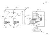
- FIG. 1 schematically shows an example of the wire saw of the present invention. Wire saw 101 shown in FIG. are doing.
- the wire saw 101 shown in FIG. 1 includes tension adjusting mechanisms 104 and 104', a mechanism 105 for sending out a work downward, a coolant supply mechanism 106, traversers 108 and 108', pulleys 109 and 109', a grooved roller drive motor 110, and a wire reel.
- Drive motors 111 and 111' are also provided as optional components of the wire saw 101 of the present invention.
- the fixed abrasive wire 102 is a wire with abrasive grains fixed to its surface. As shown in FIG. 1, the fixed abrasive wire 102 is let out from a first bobbin 107, which is one of the wire reels, passes through a traverser 108, a tension adjustment mechanism 104, a pulley 109, and onto two grooved rollers 103. After being wound up to about 500 times, it passes through a pulley 109', another tension adjusting mechanism 104', a traverser 108', and is wound on a second bobbin 107' which is another wire reel. Thus, in the wire saw 101, the fixed abrasive wire 102 is wound around a plurality of grooved rollers 103 to form a wire row.
- the first bobbin 107 stores unused portions of the fixed abrasive wire 102 .
- a second bobbin 107 ′ collects the portion used for cutting the fixed abrasive wire 102 .
- the first bobbin 107 and the second bobbin 107' are rotationally driven by wire reel drive motors 111 and 111' to control the speed of the grooved roller drive motor 110 and the speed of the wire reel drive motors 111 and 111', respectively. By doing so, the tension applied to the fixed abrasive wire 102 can be adjusted.
- the cylindrical work w When cutting the cylindrical work w, the cylindrical work w is held by the mechanism 105 for sending the cylindrical work w downward, and is relatively pushed down from the radial direction I of the cylindrical work w, and wound around the grooved roller 103. A wire train of wires 102 is fed out.
- the wire saw 101 of the present invention was used to cut the fixed abrasive wire 102 from the first bobbin 107 storing the unused portion of the fixed abrasive wire 102 by the reciprocating movement of the fixed abrasive wire 102.
- the fixed abrasive wire 102 is configured to travel back and forth in the direction (advance direction F shown in FIG. 2) toward the second bobbin 107' from which the portion is recovered. More specifically, in the reciprocating running that repeats the feeding of the fixed abrasive wire 102 in the forward direction F shown in FIG. is larger than the amount of retraction in the retraction direction B, and as a result, the fixed abrasive wire 102 is sent in the direction F toward the second bobbin 107' from the first bobbin 107. .
- the controller 115 provided in the wire saw 101 of the present invention transfers part of the fixed abrasive wire 102 used for cutting the first cylindrical work to the second bobbin after finishing cutting the first cylindrical work. 107' toward the first bobbin 107 (in retraction method B shown in FIG. 2), and the unwound portion of the fixed abrasive wire 102 in a direction from the first bobbin 107 toward the second bobbin 107'. It is configured to be controlled to start cutting the second cylindrical work while feeding in the forward direction F shown in FIG. 2 .
- the controller 115 controls the operations of the wire reel drive motors 111 and 111' and the grooved roller drive motor 110 via wires 116, 117 and 118. Thereby, as described above, the controller 115 unwinds part of the fixed abrasive wire 102 used for cutting the first cylindrical workpiece in the backward direction B, and moves the unwound portion of the fixed abrasive wire 102 forward. While feeding in the direction F, it is controlled to start cutting the second cylindrical work.
- the work cutting method of the present invention can be performed using, for example, the wire saw of the present invention, but it can also be performed with devices other than the wire saw of the present invention.
- the work cutting method of the present invention includes a step of cutting the first cylindrical work w with the fixed abrasive wire 102 .
- the fixed abrasive wire 102 is reciprocated in the axial direction while the first cylindrical workpiece w is relatively fixed in the radial direction I as shown in FIG.
- the first cylindrical workpiece w is cut into wafers by pressing against the wire row of the abrasive grain wire 102 and cutting and feeding.
- the reciprocating movement of the fixed abrasive wire is performed by sending the fixed abrasive wire 102 in the direction (advance direction F shown in FIG. 2) from the first bobbin 107 to the second bobbin 107'. It is a round trip.
- part of the fixed abrasive wire 102 used for cutting the first cylindrical work w is cut into the second from the first bobbin 107' toward the first bobbin 107 (ie, in the backward direction B).
- This rewinding can be performed, for example, by using the controller 115 to further control the operation of the grooved drive roller 110 in addition to the wire reel drive motors 111 and 111'.
- the work cutting method of the present invention includes a step of cutting the second cylindrical work w with the fixed abrasive wire 102 after the unwinding step.
- the unwound portion of the fixed abrasive wire 102 is fed in the direction (advance direction) F toward the second bobbin 107' from the first bobbin 107 to start cutting the second cylindrical workpiece w. .
- Feeding of the fixed abrasive wire 102 in cutting the second workpiece can also be performed by using the controller 115 to further control the operation of the grooved drive roller 110 in addition to the wire reel drive motors 111 and 111'.
- the cutting of the second cylindrical work can be started at the portion of the fixed abrasive wire 102 that has been used once, and the thickness of the wafer at the start of cutting can be reduced. can be prevented, and as a result, thickness unevenness of the wafer cut out from the workpiece w can be suppressed.
- the part used once after reciprocating travel is not reused, but thrown away. rice field. Therefore, conventionally, as in the present invention, the part of the fixed abrasive wire used for cutting one work is rewound, and when cutting the other work, the rewound part is sent forward and cut. was not done.
- L1 is the distance of the fixed abrasive wire 102 sent in the backward direction B to be unwound from the second bobbin 107 ′ toward the first bobbin 107 in the unwinding process.
- the diameter of the second cylindrical work w is set to D1
- the cutting feed distance to the second cylindrical work w becomes D1 ⁇ 1/6.
- S2 is the fixed abrasive wire 102 sent in the forward direction F from the first bobbin 107 to the second bobbin 107 ′ until the cutting feed distance to the second cylindrical work becomes D1 ⁇ 1/2. Distance.
- the thickness is the thinnest at the beginning of cutting, and the thickness changes sharply (gets thicker) as the cutting position changes.
- the inventors found that the thickness change when cutting and feeding from the start of cutting to 1/6 of the diameter of the cylindrical work (50 mm in the case of an ingot with a diameter of 300 mm) accounted for about 50% of the total thickness change. found to occupy. Based on this knowledge, as a result of examination, by performing the unwinding process under the condition of S1 ⁇ L1 ⁇ S2, it is possible to reliably perform the portion where the thickness change is large in the portion of the fixed abrasive wire 102 that has been used once. As a result, it was found that the thickness unevenness of the wafer cut out from the workpiece w can be suppressed more reliably.
- the controller 115 can control the rewinding process under the condition that S1 ⁇ L1 ⁇ S2. Therefore, it is preferable that the controller 115 controls the wire saw 101 so as to unwind the fixed abrasive wire 102 under the condition that S1 ⁇ L1 ⁇ S2.
- Examples 1 to 5 In Examples 1 to 5, the wire saws shown in FIGS. 1 and 2 were used, and under the conditions shown in Table 1 below, the step of cutting the first cylindrical work and the step of cutting the second cylindrical work were performed. .
- the distance L1 by which the fixed abrasive wire was rewound in the rewinding process of Examples 1 to 5 is the feed distance for cutting into the second cylindrical work, which is the diameter D1 of the second cylindrical work. 1/10, 1/8, 1/6, 1/4 and 1/2 of .
- Table 2 and FIG. 3 show the thickness variation of the wafers cut out from the first cylindrical workpiece and the second cylindrical workpiece in Examples 1 to 5 and the comparative example. is shown as a relative value calculated with 100.
- Examples 3 to 5 are examples in which the rewinding process was performed under the conditions of S1 ⁇ L1 ⁇ S2.
- S1 is the amount of wire used until the cutting feed distance to the second cylindrical work becomes 1/6 of the diameter D1 of the second cylindrical work
- S2 is the cutting to the second cylindrical work. This is the amount of wire used until the feeding distance becomes 1/2 the diameter D1 of the second cylindrical work.
- the present invention is not limited to the above embodiments.
- the above-described embodiment is an example, and any device having substantially the same configuration as the technical idea described in the claims of the present invention and exhibiting the same effect is the present invention. included in the technical scope of
Landscapes
- Engineering & Computer Science (AREA)
- Mechanical Engineering (AREA)
- Finish Polishing, Edge Sharpening, And Grinding By Specific Grinding Devices (AREA)
- Processing Of Stones Or Stones Resemblance Materials (AREA)
- Mechanical Treatment Of Semiconductor (AREA)
Abstract
本発明は、ワイヤソーによるワーク切断方法であって、第一の円柱形ワークを固定砥粒ワイヤで切断する工程と、第一の円柱形ワークを切断する工程の終了後に、第一の円柱形ワークの切断に用いた固定砥粒ワイヤの一部を、第二のボビンから第一のボビンに向かって巻き戻す工程と、巻き戻す工程の後に、第二の円柱形ワークを固定砥粒ワイヤで切断する工程とを含み、第二の円柱形ワークを切断する工程では、固定砥粒ワイヤの巻き戻した部分を第一のボビンから第二のボビンに向かう方向に送りながら第二の円柱形ワークの切断を開始するワーク切断方法である。これにより、ワークから切り出すウェーハの厚さむらを抑制できる固定砥粒ワイヤによるワークの切断方法、及びワークから切り出すウェーハの厚さむらを抑制できるワイヤソーを提供できる。
Description
本発明は、ワイヤソーを使用したワークの切断方法、及びワイヤソーに関する。
従来、シリコンインゴットや化合物半導体インゴットなどからウェーハを切り出す手段として、ワイヤソーが知られている。このワイヤソーでは、複数のローラの周囲に切断用ワイヤが多数巻き掛けられることによりワイヤ列が形成されており、その切断用ワイヤが軸方向に往復駆動され、かつ、スラリが適宜供給されながら前記ワイヤ列に対してワークが切り込み送りされることにより、このワークが各ワイヤの位置で同時に切断されるようにしたものである(特許文献1参照)。
ここで、図4に、従来の一般的なワイヤソーの一例の概要を示す。図4に示すように、このワイヤソー101’は、主に、ワークwを切断するためのワイヤ102’(高張力鋼線)、ワイヤ102’を巻掛けた溝付きローラ103、ワイヤ102’の張力を調整する張力調整機構104、切断されるワークwを下方へ送り出す機構105、切断時にスラリを供給する機構106’で構成されている。
ワイヤ102’は、一方のワイヤリールである第一のボビン107から繰り出され、トラバーサ108、張力調整機構104、プーリー109を経て、溝付きローラ103に300~500回程度巻掛けられた後、プーリー109’、もう一方の張力調整機構104’、トラバーサ108’を経て、もう一方のワイヤリールである第二のボビン107’に巻き取られている。
また、溝付きローラ103は、鉄鋼製円筒の周囲にポリウレタン樹脂を圧入し、その表面に略一定のピッチで溝を切ったローラであり、巻掛けられたワイヤ102’が溝付きローラ駆動モータ110によって、一方向あるいは、予め定められた周期で往復方向に駆動できるようになっている。
第一のボビン107及び第二のボビン107’は、ワイヤリール駆動モータ111及び111’によって回転駆動され、溝付きローラ駆動モータ110の速度とワイヤリール駆動モータ111及び111’の速度とをそれぞれ制御することにより、ワイヤ102’にかかる張力を調整することが出来る。
また、図4のワークwを下方へ送り出す機構105は、図5のように、ワーク保持部112及びワークプレート113から構成されるワーク保持手段114を有しており、ワークプレート113には、ワークwに貼り付けられた接合部材(ビーム)120を介してワークwが接着される。
ワークw切断時には、ワークwを下方へ送り出す機構105によってワークWは保持されつつ相対的に押し下げられ、溝付ローラ103に巻きかけられたワイヤ102’からなるワイヤ列に対して送り出される。
このようなワイヤソー101’を用い、ワイヤ102’に張力調整機構104及び104’を用いて適当な張力をかけて、ワイヤリール駆動用モータ111及び111’によりワイヤ102’を図5に示す往復方向に走行させながら、スラリ供給機構106’から供給されたスラリを供給し、ワークwを下方へ送り出す機構105でワークwを図5に示すワーク送り方向に切り込み送りすることでワークを切断する。
一方、砥粒を含むスラリを使用せず、代わりにダイヤモンド砥粒等をワイヤの表面に固着した固定砥粒ワイヤを使用して、ワークを切断する方法も知られており、直径150mm程度以下の小直径インゴットの切断には一部で実用化している。
この固定砥粒ワイヤによる切断では、図4に示したワイヤソーの鋼線ワイヤの代わりに固定砥粒ワイヤを装着し、スラリを砥粒が含まれない冷却水などのクーラントに変えることで、一般的なワイヤソーをそのまま使用することができる。
固定砥粒ワイヤによる切断は、ウェーハ表裏面に導入されるダメージが小さいため、これらのダメージを除去する、後工程での取り代を削減できるという利点がある。この利点を最大限に生かすためには、切り出すウェーハの厚さばらつきを小さくする必要がある。
しかし、固定砥粒ワイヤによる切断では、ワーク切断開始時において、固定砥粒ワイヤの表面の砥粒の初期摩耗が大きいことと、砥粒の切れ味が十分でないためワイヤがワークの軸方向に振動することとから、切り始め部分のウェーハの厚さが薄くなり、ウェーハの厚さむら(TTV:Total Thickness Variation)が大きくなってしまうという問題があった。
特許文献2には、固定砥粒ワイヤソーによるワーク(被加工物)の切断時に、連続的にワイヤを送り出してワークを切断した後に、送り出した長さより短い長さを後退方向に巻き取りながら同じワークを切断し、これの工程を繰り返して1つのワークを切断する方法が記載されている。
特許文献3には、遊離砥粒によるワイヤソーにおいて、一度切断に使用したワイヤを再利用する際に、ワイヤ張力を前回の87~95%、新線供給量を125%以上とし、断線防止と反り悪化を抑制する切断方法が記載されている
特許文献4には、固定砥粒ワイヤソーのワーク切断時に、基準厚さバラツキに対して、切断後のウェーハのインゴットの一端から他端までのウェーハの厚さを測定し厚さバラツキを算出し、基準厚さバラツキと算出した厚さバラツキの差を比較して、正常か異常の判定を行う切断工程の管理方法が記載されている。
TTVが大きいウェーハをラップ、研磨加工する場合に種々の問題点があり、例えばラップ工程でウェーハの厚さ精度を出そうとすると、厚さが薄いウェーハに揃えるように加工するため、ウェーハのフラットネス精度が悪化する方向に進んで仕上り精度がよくならないという問題点がある。そのため、ワイヤソーによるワークの切断では、ワークから切り出すウェーハの厚さむらが小さいことが望まれる。
本発明は、前述のような問題に鑑みてなされたもので、ワークから切り出すウェーハの厚さむらを抑制できる固定砥粒ワイヤによるワークの切断方法、及びワークから切り出すウェーハの厚さむらを抑制できるワイヤソーを提供することを目的とする。
上記課題を解決するために、本発明では、表面に砥粒が固着された固定砥粒ワイヤを、複数の溝付ローラに巻きかけることによってワイヤ列を形成し、前記固定砥粒ワイヤを軸方向に往復走行させながら、円柱形ワークを前記円柱形ワークの径方向から相対的に前記ワイヤ列に対して押し当てて切り込み送りし、前記円柱形ワークをウェーハ状に切断するワイヤソーによるワーク切断方法であって、
前記固定砥粒ワイヤの前記往復走行は、前記固定砥粒ワイヤの未使用の部分を貯蔵している第一のボビンから、前記固定砥粒ワイヤの切断に使用した部分を回収する第二のボビンに向かう方向に、前記固定砥粒ワイヤを送っていく往復走行であり、
第一の円柱形ワークを前記固定砥粒ワイヤで切断する工程と、
前記第一の円柱形ワークを切断する工程の終了後に、前記第一の円柱形ワークの切断に用いた前記固定砥粒ワイヤの一部を、前記第二のボビンから前記第一のボビンに向かって巻き戻す工程と、
前記巻き戻す工程の後に、第二の円柱形ワークを前記固定砥粒ワイヤで切断する工程と
を含み、
前記第二の円柱形ワークを切断する工程では、前記固定砥粒ワイヤの前記巻き戻した部分を前記第一のボビンから前記第二のボビンに向かう前記方向に送りながら前記第二の円柱形ワークの切断を開始することを特徴とするワーク切断方法を提供する。
前記固定砥粒ワイヤの前記往復走行は、前記固定砥粒ワイヤの未使用の部分を貯蔵している第一のボビンから、前記固定砥粒ワイヤの切断に使用した部分を回収する第二のボビンに向かう方向に、前記固定砥粒ワイヤを送っていく往復走行であり、
第一の円柱形ワークを前記固定砥粒ワイヤで切断する工程と、
前記第一の円柱形ワークを切断する工程の終了後に、前記第一の円柱形ワークの切断に用いた前記固定砥粒ワイヤの一部を、前記第二のボビンから前記第一のボビンに向かって巻き戻す工程と、
前記巻き戻す工程の後に、第二の円柱形ワークを前記固定砥粒ワイヤで切断する工程と
を含み、
前記第二の円柱形ワークを切断する工程では、前記固定砥粒ワイヤの前記巻き戻した部分を前記第一のボビンから前記第二のボビンに向かう前記方向に送りながら前記第二の円柱形ワークの切断を開始することを特徴とするワーク切断方法を提供する。
第一の円柱形ワークを固定砥粒で切断した後に、第一の円柱形ワークの切断に用いた固定砥粒ワイヤの一部を第二のボビンから第一のボビンに向かって巻き戻し、第二の円柱形ワークを固定砥粒ワイヤで切断する際に、固定砥粒ワイヤの巻き戻した部分を第一のボビンから第二のボビンに向かう方向(前進方向)に送りながら第二の円柱形ワークの切断を開始することで、第二の円柱形ワークの切り始めを固定砥粒ワイヤの一度使用した部分で行うことができる。それにより、切り始めのウェーハ厚さが小さくなることを防ぐことができ、その結果、ワークから切り出すウェーハの厚さむらを抑制できる。
前記巻き戻す工程において、前記第二のボビンから前記第一のボビンに向かって巻き戻す前記固定砥粒ワイヤの距離をL1とし、
前記第二の円柱形ワークの直径をD1とし、
前記第二の円柱形ワークを切断する工程において、前記第二の円柱形ワークへの切り込み送り距離がD1×1/6になるまでに、前記第一のボビンから前記第二のボビンに向かう前記方向に送る前記固定砥粒ワイヤの距離をS1とし、
前記第二の円柱形ワークへの前記切り込み送り距離がD1×1/2になるまでに、前記第一のボビンから前記第二のボビンに向かう前記方向に送る前記固定砥粒ワイヤの距離をS2として、
S1≦L1≦S2になる条件で、前記巻き戻す工程を行うことが好ましい。
前記第二の円柱形ワークの直径をD1とし、
前記第二の円柱形ワークを切断する工程において、前記第二の円柱形ワークへの切り込み送り距離がD1×1/6になるまでに、前記第一のボビンから前記第二のボビンに向かう前記方向に送る前記固定砥粒ワイヤの距離をS1とし、
前記第二の円柱形ワークへの前記切り込み送り距離がD1×1/2になるまでに、前記第一のボビンから前記第二のボビンに向かう前記方向に送る前記固定砥粒ワイヤの距離をS2として、
S1≦L1≦S2になる条件で、前記巻き戻す工程を行うことが好ましい。
巻き戻す工程において巻き戻す固定砥粒ワイヤの距離L1をS1≦L1≦S2になる条件とすることで、ワークから切り出すウェーハの厚さむらをより確実に抑制できる。
また、本発明では、表面に砥粒が固着された固定砥粒ワイヤを、複数の溝付ローラに巻きかけることによってワイヤ列を形成し、前記固定砥粒ワイヤを軸方向に往復走行させながら、円柱形ワークを前記円柱形ワークの径方向から相対的に前記ワイヤ列に対して押し当てて切り込み送りし、前記円柱形ワークをウェーハ状に切断するワイヤソーであって、
前記ワイヤソーは、前記固定砥粒ワイヤの前記往復走行が、前記固定砥粒ワイヤの未使用の部分を貯蔵している第一のボビンから、前記固定砥粒ワイヤの切断に使用した部分を回収する第二のボビンに向かう方向に、前記固定砥粒ワイヤを送っていく往復走行となるように構成されており、
前記ワイヤソーは、第一の円柱形ワークの切断終了後に、前記第一の円柱形ワークの切断に用いた前記固定砥粒ワイヤの一部を、前記第二のボビンから前記第一のボビンに向かって巻き戻し、前記固定砥粒ワイヤの前記巻き戻した部分を前記第一のボビンから前記第二のボビンに向かう前記方向に送りながら第二の円柱形ワークの切断を開始するように制御するコントローラを具備するものであることを特徴とするワイヤソーを提供する。
前記ワイヤソーは、前記固定砥粒ワイヤの前記往復走行が、前記固定砥粒ワイヤの未使用の部分を貯蔵している第一のボビンから、前記固定砥粒ワイヤの切断に使用した部分を回収する第二のボビンに向かう方向に、前記固定砥粒ワイヤを送っていく往復走行となるように構成されており、
前記ワイヤソーは、第一の円柱形ワークの切断終了後に、前記第一の円柱形ワークの切断に用いた前記固定砥粒ワイヤの一部を、前記第二のボビンから前記第一のボビンに向かって巻き戻し、前記固定砥粒ワイヤの前記巻き戻した部分を前記第一のボビンから前記第二のボビンに向かう前記方向に送りながら第二の円柱形ワークの切断を開始するように制御するコントローラを具備するものであることを特徴とするワイヤソーを提供する。
このようなワイヤソーであれば、第二の円柱形ワークの切り始めを固定砥粒ワイヤの一度使用した部分で行うことができる。それにより、切り始めのウェーハ厚さが小さくなることを防ぐことができ、その結果、ワークから切り出すウェーハの厚さむらを抑制できるものとなる。
前記コントローラが、
前記第二のボビンから前記第一のボビンに向かって巻き戻す前記固定砥粒ワイヤの距離をL1とし、
前記第二の円柱形ワークの直径をD1とし、
前記第二の円柱形ワークへの切り込み送り距離がD1×1/6になるまでに、前記第一のボビンから前記第二のボビンに向かう前記方向に送る前記固定砥粒ワイヤの距離をS1とし、
前記第二の円柱形ワークへの前記切り込み送り距離がD1×1/2になるまでに、前記第一のボビンから前記第二のボビンに向かう前記方向に送る前記固定砥粒ワイヤの距離をS2として、
S1≦L1≦S2になる条件で前記固定砥粒ワイヤを巻き戻すように、前記ワイヤソーを制御するものであることが好ましい。
前記第二のボビンから前記第一のボビンに向かって巻き戻す前記固定砥粒ワイヤの距離をL1とし、
前記第二の円柱形ワークの直径をD1とし、
前記第二の円柱形ワークへの切り込み送り距離がD1×1/6になるまでに、前記第一のボビンから前記第二のボビンに向かう前記方向に送る前記固定砥粒ワイヤの距離をS1とし、
前記第二の円柱形ワークへの前記切り込み送り距離がD1×1/2になるまでに、前記第一のボビンから前記第二のボビンに向かう前記方向に送る前記固定砥粒ワイヤの距離をS2として、
S1≦L1≦S2になる条件で前記固定砥粒ワイヤを巻き戻すように、前記ワイヤソーを制御するものであることが好ましい。
このようなコントローラを具備したものであれば、ワークから切り出すウェーハの厚さむらをより確実に抑制できるものとなる。
以上のように、本発明のワーク切断方法であれば、切り始めのウェーハ厚さが小さくなることを防ぐことができ、その結果、ワークから切り出すウェーハの厚さむらを抑制できる。厚さむらの小さいウェーハであれば、後工程の取り代を削減することができる。
また、本発明のワイヤソーであれば、切り始めのウェーハ厚さが小さくなることを防ぐことができ、その結果、ワークから切り出すウェーハの厚さむらを抑制できるものとなる。厚さむらの小さいウェーハであれば、後工程の取り代を削減することができる。
上述のように、ワークから切り出すウェーハの厚さむらを抑制できる固定砥粒ワイヤによるワークの切断方法、及びワークから切り出すウェーハの厚さむらを抑制できるワイヤソーの開発が求められていた。
本発明者らは、上記課題について鋭意検討を重ねた結果、第一の円柱形ワークを固定砥粒ワイヤで切断した後に、第一の円柱形ワークの切断に用いた固定砥粒ワイヤの一部を巻き戻し、第二の円柱形ワークを固定砥粒ワイヤで切断する際に、固定砥粒ワイヤの巻き戻した部分を前進方向に送りながら第二の円柱形ワークの切断を開始することで、第二の円柱形ワークの切り始めを固定砥粒ワイヤの一度使用した部分で行うことができ、切り始めのウェーハ厚さが小さくなることを防ぐことができ、その結果、ワークから切り出すウェーハの厚さむらを抑制できることを見出し、本発明を完成させた。
即ち、本発明は、表面に砥粒が固着された固定砥粒ワイヤを、複数の溝付ローラに巻きかけることによってワイヤ列を形成し、前記固定砥粒ワイヤを軸方向に往復走行させながら、円柱形ワークを前記円柱形ワークの径方向から相対的に前記ワイヤ列に対して押し当てて切り込み送りし、前記円柱形ワークをウェーハ状に切断するワイヤソーによるワーク切断方法であって、
前記固定砥粒ワイヤの前記往復走行は、前記固定砥粒ワイヤの未使用の部分を貯蔵している第一のボビンから、前記固定砥粒ワイヤの切断に使用した部分を回収する第二のボビンに向かう方向に、前記固定砥粒ワイヤを送っていく往復走行であり、
第一の円柱形ワークを前記固定砥粒ワイヤで切断する工程と、
前記第一の円柱形ワークを切断する工程の終了後に、前記第一の円柱形ワークの切断に用いた前記固定砥粒ワイヤの一部を、前記第二のボビンから前記第一のボビンに向かって巻き戻す工程と、
前記巻き戻す工程の後に、第二の円柱形ワークを前記固定砥粒ワイヤで切断する工程と
を含み、
前記第二の円柱形ワークを切断する工程では、前記固定砥粒ワイヤの前記巻き戻した部分を前記第一のボビンから前記第二のボビンに向かう前記方向に送りながら前記第二の円柱形ワークの切断を開始することを特徴とするワーク切断方法である。
前記固定砥粒ワイヤの前記往復走行は、前記固定砥粒ワイヤの未使用の部分を貯蔵している第一のボビンから、前記固定砥粒ワイヤの切断に使用した部分を回収する第二のボビンに向かう方向に、前記固定砥粒ワイヤを送っていく往復走行であり、
第一の円柱形ワークを前記固定砥粒ワイヤで切断する工程と、
前記第一の円柱形ワークを切断する工程の終了後に、前記第一の円柱形ワークの切断に用いた前記固定砥粒ワイヤの一部を、前記第二のボビンから前記第一のボビンに向かって巻き戻す工程と、
前記巻き戻す工程の後に、第二の円柱形ワークを前記固定砥粒ワイヤで切断する工程と
を含み、
前記第二の円柱形ワークを切断する工程では、前記固定砥粒ワイヤの前記巻き戻した部分を前記第一のボビンから前記第二のボビンに向かう前記方向に送りながら前記第二の円柱形ワークの切断を開始することを特徴とするワーク切断方法である。
また、本発明は、表面に砥粒が固着された固定砥粒ワイヤを、複数の溝付ローラに巻きかけることによってワイヤ列を形成し、前記固定砥粒ワイヤを軸方向に往復走行させながら、円柱形ワークを前記円柱形ワークの径方向から相対的に前記ワイヤ列に対して押し当てて切り込み送りし、前記円柱形ワークをウェーハ状に切断するワイヤソーであって、
前記ワイヤソーは、前記固定砥粒ワイヤの前記往復走行が、前記固定砥粒ワイヤの未使用の部分を貯蔵している第一のボビンから、前記固定砥粒ワイヤの切断に使用した部分を回収する第二のボビンに向かう方向に、前記固定砥粒ワイヤを送っていく往復走行となるように構成されており、
前記ワイヤソーは、第一の円柱形ワークの切断終了後に、前記第一の円柱形ワークの切断に用いた前記固定砥粒ワイヤの一部を、前記第二のボビンから前記第一のボビンに向かって巻き戻し、前記固定砥粒ワイヤの前記巻き戻した部分を前記第一のボビンから前記第二のボビンに向かう前記方向に送りながら第二の円柱形ワークの切断を開始するように制御するコントローラを具備するものであることを特徴とするワイヤソーである。
前記ワイヤソーは、前記固定砥粒ワイヤの前記往復走行が、前記固定砥粒ワイヤの未使用の部分を貯蔵している第一のボビンから、前記固定砥粒ワイヤの切断に使用した部分を回収する第二のボビンに向かう方向に、前記固定砥粒ワイヤを送っていく往復走行となるように構成されており、
前記ワイヤソーは、第一の円柱形ワークの切断終了後に、前記第一の円柱形ワークの切断に用いた前記固定砥粒ワイヤの一部を、前記第二のボビンから前記第一のボビンに向かって巻き戻し、前記固定砥粒ワイヤの前記巻き戻した部分を前記第一のボビンから前記第二のボビンに向かう前記方向に送りながら第二の円柱形ワークの切断を開始するように制御するコントローラを具備するものであることを特徴とするワイヤソーである。
以下、本発明について図面を参照しながら詳細に説明するが、本発明はこれらに限定されるものではない。
(ワイヤソー)
図1に、本発明のワイヤソーの一例を概略的に示す。図1に示すワイヤソー101は、固定砥粒ワイヤ102と、複数(図1では2つ)の溝付きローラ103と、第一のボビン107と、第二のボビン107’と、コントローラ115とを具備している。
図1に、本発明のワイヤソーの一例を概略的に示す。図1に示すワイヤソー101は、固定砥粒ワイヤ102と、複数(図1では2つ)の溝付きローラ103と、第一のボビン107と、第二のボビン107’と、コントローラ115とを具備している。
図1に示すワイヤソー101は、張力調整機構104及び104’、ワークを下方へ送り出す機構105、クーラント供給機構106、トラバーサ108及び108’、プーリー109及び109’、溝付きローラ駆動モータ110、ワイヤリール駆動モータ111及び111’を、本発明のワイヤソー101の任意部材として、更に具備している。
固定砥粒ワイヤ102は、表面に砥粒が固着されているワイヤである。図1に示すように、固定砥粒ワイヤ102は、一方のワイヤリールである第一のボビン107から繰り出され、トラバーサ108、張力調整機構104、プーリー109を経て、2つの溝付きローラ103に300~500回程度巻掛けられた後、プーリー109’、もう一方の張力調整機構104’、トラバーサ108’を経て、もう一方のワイヤリールである第二のボビン107’に巻き取られている。これにより、ワイヤソー101では、固定砥粒ワイヤ102が、複数の溝付きローラ103に巻きかけられることにより、ワイヤ列を形成している。
第一のボビン107は、固定砥粒ワイヤ102の未使用部分を貯蔵するものである。第二のボビン107’は、固定砥粒ワイヤ102の切断に使用した部分を回収するものである。第一のボビン107及び第二のボビン107’は、ワイヤリール駆動モータ111及び111’によって回転駆動され、溝付きローラ駆動モータ110の速度とワイヤリール駆動モータ111及び111’の速度とをそれぞれ制御することにより、固定砥粒ワイヤ102にかかる張力を調整することが出来る。
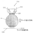
また、図1のワークwを下方へ送り出す機構105は、図2のように、ワーク保持部112及びワークプレート113から構成されるワーク保持手段114を有しており、ワークプレート113には、円柱形ワークwに貼り付けられた接合部材(ビーム)120を介して円柱形ワークwが接着される。
円柱形ワークw切断時には、円柱形ワークwを下方へ送り出す機構105によって円柱形ワークwは保持されつつ円柱形ワークwの径方向Iから相対的に押し下げられ、溝付ローラ103に巻きかけられたワイヤ102からなるワイヤ列に対して送り出される。
このようなワイヤソー101を用い、ワイヤ102に張力調整機構104及び104’を用いて適当な張力をかけて、ワイヤリール駆動用モータ111及び111’により固定砥粒ワイヤ102を往復方向に走行させながら、クーラント供給機構106からクーラントを供給し、ワークwを下方へ送り出す機構105でワークwを図2に示すワーク送り方向Iに切り込み送りすることでワークを切断する。
本発明のワイヤソー101は、固定砥粒ワイヤ102の上記往復走行が、固定砥粒ワイヤ102の未使用の部分を貯蔵している第一のボビン107から、固定砥粒ワイヤ102の切断に使用した部分を回収する第二のボビン107’に向かう方向(図2に示す前進方向F)に、固定砥粒ワイヤ102を送っていく往復走行となるように構成されている。より具体的には、図2に示す前進方向Fでの固定砥粒ワイヤ102の送りと、後退方向Bでの固定砥粒ワイヤ102の後退とを繰り返す往復走行において、前進方向Fでの前進量を後退方向Bでの後退量よりも大きくして、結果的に固定砥粒ワイヤ102が第一のボビン107から第二のボビン107’に向かう方向Fに送られていくように構成されている。
また、本発明のワイヤソー101が具備するコントローラ115は、第一の円柱形ワークの切断終了後に、第一の円柱形ワークの切断に用いた固定砥粒ワイヤ102の一部を、第二のボビン107’から第一のボビン107に向かって(図2に示す後退方法Bで)巻き戻し、固定砥粒ワイヤ102の巻き戻した部分を第一のボビン107から第二のボビン107’に向かう方向(図2に示す前進方向F)に送りながら第二の円柱形ワークの切断を開始するように制御するように構成されている。
図1に示すワイヤソー101では、コントローラ115が、配線116、117及び118を介して、ワイヤリール駆動モータ111及び111’、並びに溝付きローラ駆動モータ110の動作を制御する。それにより、コントローラ115が、上記の通り、第一の円柱形ワークの切断に用いた固定砥粒ワイヤ102の一部を後退方向Bに巻き戻し、固定砥粒ワイヤ102の巻き戻した部分を前進方向Fに送りながら第二の円柱形ワークの切断を開始するように制御する。
(ワーク切断方法)
本発明のワーク切断方法は、例えば、本発明のワイヤソーを用いて行うことができるが、本発明のワイヤソー以外の装置で行うこともできる。
本発明のワーク切断方法は、例えば、本発明のワイヤソーを用いて行うことができるが、本発明のワイヤソー以外の装置で行うこともできる。
以下、本発明のワーク切断方法の一例として、図1及び図2に示すワイヤソー101を用いた例を説明する。
本発明のワークの切断方法は、第一の円柱形ワークwを固定砥粒ワイヤ102で切断する工程を含む。
第一の円柱形ワークwを切断する工程では、固定砥粒ワイヤ102を軸方向に往復走行させながら、第一の円柱形ワークwを図2に示すようにその径方向Iから相対的に固定砥粒ワイヤ102のワイヤ列に対して押し当てて切り込み送りして、第一の円柱形ワークwをウェーハ状に切断する。
固定砥粒ワイヤの往復走行は、先に説明したように、第一のボビン107から第二のボビン107’に向かう方向(図2に示す前進方向F)に、固定砥粒ワイヤ102を送っていく往復走行である。
また、本発明のワークの切断方法は、第一の円柱形ワークwを切断する工程の終了後に、第一の円柱形ワークwの切断に用いた固定砥粒ワイヤ102の一部を、第二のボビン107’から第一のボビン107に向かって(すなわち、後退方向Bに)巻き戻す工程を含む。
この巻き戻しは、例えば、コントローラ115を用いて、ワイヤリール駆動モータ111及び111’に加え溝付き駆動ローラ110を更に動作制御して行うことができる。
そして、本発明のワークの切断方法は、巻き戻す工程の後に、第二の円柱形ワークwを前記固定砥粒ワイヤ102で切断する工程を含む。
この工程では、固定砥粒ワイヤ102の巻き戻した部分を第一のボビン107から第二のボビン107’に向かう方向(前進方向)Fに送りながら第二の円柱形ワークwの切断を開始する。
第二のワークの切断における固定砥粒ワイヤ102の送りも、コントローラ115を用いて、ワイヤリール駆動モータ111及び111’に加え溝付き駆動ローラ110を更に動作制御して行うことができる。
このような本発明のワークの切断方法によれば、第二の円柱形ワークの切り始めを固定砥粒ワイヤ102の一度使用した部分で行うことができ、切り始めのウェーハ厚さが小さくなることを防ぐことができ、その結果、ワークwから切り出すウェーハの厚さむらを抑制できる。
なお、固定砥粒ワイヤは使用することにより摩耗劣化しワイヤ径が小さくなるため、従来の固定砥粒ワイヤを用いた切断では、往復走行を経て一度使用した部分は、再使用せず、使い捨てていた。そのため、従来では、本発明のように、固定砥粒ワイヤのうち1つのワークの切断に使用した部分を巻き戻し、他のワークの切断の際に、巻き戻した部分を前進方向に送って切断を開始することは行なわれていなかった。
更に、巻き戻す工程を、S1≦L1≦S2になる条件で行うことが好ましい。ここで、L1は、巻き戻す工程において、第二のボビン107’から第一のボビン107に向かって巻き戻す後退方向Bに送る、固定砥粒ワイヤ102の距離である。S1は、第二の円柱形ワークwの直径をD1とし、第二の円柱形ワークwを切断する工程において、第二の円柱形ワークwへの切り込み送り距離がD1×1/6になるまでに、第一のボビン107から第二のボビン107’に向かう前進方向Fに送る、固定砥粒ワイヤ102の距離である。S2は、第二の円柱形ワークへの切り込み送り距離がD1×1/2になるまでに、第一のボビン107から第二のボビン107’に向かう前進方向Fに送る固定砥粒ワイヤ102の距離である。
固定砥粒ワイヤを用いたワーク切断では、切り始めが最も薄く、切断位置の変化に伴い厚さ急峻に変化していく(厚くなっていく)。
発明者らは、特に、切り始めから円柱状ワークの直径の1/6(直径300mmのインゴットの場合、50mm)まで切り込み送りした際の厚さ変化が、全体の厚さ変化の約50%を占めることを見出した。この知見に基づき、検討した結果、巻き戻す工程をS1≦L1≦S2になる条件で行うことで、厚さ変化が大きくなる部分を固定砥粒ワイヤ102の一度使用した部分で確実に行うことができ、その結果、ワークwから切り出すウェーハの厚さむらをより確実に抑制できることが分かった。
巻き戻す工程をS1≦L1≦S2になる条件で行うことは、例えばコントローラ115で制御することができる。そのため、コントローラ115は、S1≦L1≦S2になる条件で固定砥粒ワイヤ102を巻き戻すように、ワイヤソー101を制御するものであることが好ましい。
以下、実施例及び比較例を用いて本発明を具体的に説明するが、本発明はこれらに限定されるものではない。
(実施例1~5)
実施例1~5では、図1及び図2に示すワイヤソーを用い、以下の表1に示す条件で、第一の円柱形ワークの切断工程、及び第二の円柱形ワークの切断工程を行った。
実施例1~5では、図1及び図2に示すワイヤソーを用い、以下の表1に示す条件で、第一の円柱形ワークの切断工程、及び第二の円柱形ワークの切断工程を行った。
また、実施例1~5では、第一の円柱形ワーク切断工程後に、第一の円柱形ワークの切断に用いた固定砥粒ワイヤのうち以下の表2に示す距離L1だけ、第二のボビンから第一のボビンに巻き戻す工程を行い、次いで、固定砥粒ワイヤの巻き戻した部分を第一のボビンから第二のボビンに向かう方向に送りながら、第二の円柱状ワークの切断工程を開始した。
表2に示すように、実施例1~5の巻き戻す工程において固定砥粒ワイヤを巻き戻した距離L1は、第二の円柱形ワークへの切り込み送り距離が第二の円柱形ワークの直径D1の1/10、1/8、1/6、1/4及び1/2になるまでのワイヤ使用量と同じにした。
(比較例)
図1に示すコントローラ115の代わりに、第一の円柱形ワークの切断に用いた固定砥粒ワイヤの一部を巻き戻す制御を行う機能を持たないコントローラを具備したこと以外は図1に示したものと同様のワイヤソーを用いて、表1に示す条件で第一の円柱形ワーク及び第二の円柱形ワークの切断を順に行った。すなわち、比較例では、表2に示すように、第一の円柱形ワークの切断に用いた固定砥粒ワイヤを巻き戻さなかった。
図1に示すコントローラ115の代わりに、第一の円柱形ワークの切断に用いた固定砥粒ワイヤの一部を巻き戻す制御を行う機能を持たないコントローラを具備したこと以外は図1に示したものと同様のワイヤソーを用いて、表1に示す条件で第一の円柱形ワーク及び第二の円柱形ワークの切断を順に行った。すなわち、比較例では、表2に示すように、第一の円柱形ワークの切断に用いた固定砥粒ワイヤを巻き戻さなかった。
以下の表2、及び図3に、実施例1~5、並びに比較例において、第一の円柱形ワーク及び第二の円柱形ワークから切り出したウェーハの厚さばらつきを、比較例の厚さばらつきを100として算出した相対値として、合わせて示す。

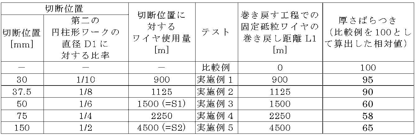
表2に示した結果から明らかなように、固定砥粒ワイヤの第一の円柱形ワークの切断に使用した一部を巻き戻し、固定砥粒の巻き戻した部分を第一のボビンから第二のボビンに向かう方向に送りながら第二の円柱状ワークの切断工程を開始した実施例1~5では、固定砥粒ワイヤの第一の円柱形ワークの切断に使用した一部を巻き戻さなかった比較例に比べ、ウェーハの厚さばらつきを小さくすることができ、ワークから切り出すウェーハの厚さむらを抑制できた。
また、巻き戻す工程での固定砥粒ワイヤの巻き戻し距離L1を、それぞれ1500mm、2250mm及び4500mmとした実施例3~5は、実施例1及び2よりもウェーハの厚さむらを更に抑制できた。実施例3~5は、巻き戻す工程を、S1≦L1≦S2になる条件で行った例である。S1は、第二の円柱形ワークへの切り込み送り距離が第二の円柱形ワークの直径D1の1/6になるまでのワイヤ使用量であり、S2は、第二の円柱形ワークへの切り込み送り距離が第二の円柱形ワークの直径D1の1/2になるまでのワイヤ使用量である。
なお、本発明は、上記実施形態に限定されるものではない。上記実施形態は例示であり、本発明の特許請求の範囲に記載された技術的思想と実質的に同一な構成を有し、同様な作用効果を奏するものは、いかなるものであっても本発明の技術的範囲に包含される。
Claims (4)
- 表面に砥粒が固着された固定砥粒ワイヤを、複数の溝付ローラに巻きかけることによってワイヤ列を形成し、前記固定砥粒ワイヤを軸方向に往復走行させながら、円柱形ワークを前記円柱形ワークの径方向から相対的に前記ワイヤ列に対して押し当てて切り込み送りし、前記円柱形ワークをウェーハ状に切断するワイヤソーによるワーク切断方法であって、
前記固定砥粒ワイヤの前記往復走行は、前記固定砥粒ワイヤの未使用の部分を貯蔵している第一のボビンから、前記固定砥粒ワイヤの切断に使用した部分を回収する第二のボビンに向かう方向に、前記固定砥粒ワイヤを送っていく往復走行であり、
第一の円柱形ワークを前記固定砥粒ワイヤで切断する工程と、
前記第一の円柱形ワークを切断する工程の終了後に、前記第一の円柱形ワークの切断に用いた前記固定砥粒ワイヤの一部を、前記第二のボビンから前記第一のボビンに向かって巻き戻す工程と、
前記巻き戻す工程の後に、第二の円柱形ワークを前記固定砥粒ワイヤで切断する工程と
を含み、
前記第二の円柱形ワークを切断する工程では、前記固定砥粒ワイヤの前記巻き戻した部分を前記第一のボビンから前記第二のボビンに向かう前記方向に送りながら前記第二の円柱形ワークの切断を開始することを特徴とするワーク切断方法。 - 前記巻き戻す工程において、前記第二のボビンから前記第一のボビンに向かって巻き戻す前記固定砥粒ワイヤの距離をL1とし、
前記第二の円柱形ワークの直径をD1とし、
前記第二の円柱形ワークを切断する工程において、前記第二の円柱形ワークへの切り込み送り距離がD1×1/6になるまでに、前記第一のボビンから前記第二のボビンに向かう前記方向に送る前記固定砥粒ワイヤの距離をS1とし、
前記第二の円柱形ワークへの前記切り込み送り距離がD1×1/2になるまでに、前記第一のボビンから前記第二のボビンに向かう前記方向に送る前記固定砥粒ワイヤの距離をS2として、
S1≦L1≦S2になる条件で、前記巻き戻す工程を行うことを特徴とする請求項1に記載のワーク切断方法。 - 表面に砥粒が固着された固定砥粒ワイヤを、複数の溝付ローラに巻きかけることによってワイヤ列を形成し、前記固定砥粒ワイヤを軸方向に往復走行させながら、円柱形ワークを前記円柱形ワークの径方向から相対的に前記ワイヤ列に対して押し当てて切り込み送りし、前記円柱形ワークをウェーハ状に切断するワイヤソーであって、
前記ワイヤソーは、前記固定砥粒ワイヤの前記往復走行が、前記固定砥粒ワイヤの未使用の部分を貯蔵している第一のボビンから、前記固定砥粒ワイヤの切断に使用した部分を回収する第二のボビンに向かう方向に、前記固定砥粒ワイヤを送っていく往復走行となるように構成されており、
前記ワイヤソーは、第一の円柱形ワークの切断終了後に、前記第一の円柱形ワークの切断に用いた前記固定砥粒ワイヤの一部を、前記第二のボビンから前記第一のボビンに向かって巻き戻し、前記固定砥粒ワイヤの前記巻き戻した部分を前記第一のボビンから前記第二のボビンに向かう前記方向に送りながら第二の円柱形ワークの切断を開始するように制御するコントローラを具備するものであることを特徴とするワイヤソー。 - 前記コントローラが、
前記第二のボビンから前記第一のボビンに向かって巻き戻す前記固定砥粒ワイヤの距離をL1とし、
前記第二の円柱形ワークの直径をD1とし、
前記第二の円柱形ワークへの切り込み送り距離がD1×1/6になるまでに、前記第一のボビンから前記第二のボビンに向かう前記方向に送る前記固定砥粒ワイヤの距離をS1とし、
前記第二の円柱形ワークへの前記切り込み送り距離がD1×1/2になるまでに、前記第一のボビンから前記第二のボビンに向かう前記方向に送る前記固定砥粒ワイヤの距離をS2として、
S1≦L1≦S2になる条件で前記固定砥粒ワイヤを巻き戻すように、前記ワイヤソーを制御するものであることを特徴とする請求項3に記載のワイヤソー。
Applications Claiming Priority (2)
| Application Number | Priority Date | Filing Date | Title |
|---|---|---|---|
| JP2021-203952 | 2021-12-16 | ||
| JP2021203952A JP2023089451A (ja) | 2021-12-16 | 2021-12-16 | ワークの切断方法及びワイヤソー |
Publications (1)
| Publication Number | Publication Date |
|---|---|
| WO2023112490A1 true WO2023112490A1 (ja) | 2023-06-22 |
Family
ID=86774419
Family Applications (1)
| Application Number | Title | Priority Date | Filing Date |
|---|---|---|---|
| PCT/JP2022/039588 Ceased WO2023112490A1 (ja) | 2021-12-16 | 2022-10-24 | ワークの切断方法及びワイヤソー |
Country Status (3)
| Country | Link |
|---|---|
| JP (1) | JP2023089451A (ja) |
| TW (1) | TW202327794A (ja) |
| WO (1) | WO2023112490A1 (ja) |
Citations (5)
| Publication number | Priority date | Publication date | Assignee | Title |
|---|---|---|---|---|
| JP2010105061A (ja) * | 2008-10-28 | 2010-05-13 | Yasunaga Corp | ワイヤソー装置 |
| JP2011020197A (ja) * | 2009-07-14 | 2011-02-03 | Shin Etsu Handotai Co Ltd | ワークの切断方法 |
| JP2015074037A (ja) * | 2013-10-07 | 2015-04-20 | 株式会社安永 | 固定砥粒ワイヤソー装置及びこれを用いたウエハの製造方法 |
| JP2017077594A (ja) * | 2015-10-20 | 2017-04-27 | 信越半導体株式会社 | ワークの切断方法及びワイヤソー |
| JP2018176301A (ja) * | 2017-04-04 | 2018-11-15 | 信越半導体株式会社 | ワークの切断方法 |
Family Cites Families (2)
| Publication number | Priority date | Publication date | Assignee | Title |
|---|---|---|---|---|
| JP3566449B2 (ja) * | 1996-03-27 | 2004-09-15 | 信越半導体株式会社 | ワイヤソーによるワーク切断方法 |
| JPH10329000A (ja) * | 1997-05-30 | 1998-12-15 | Nippei Toyama Corp | ワークの加工方法、ワイヤソー及び記録媒体 |
-
2021
- 2021-12-16 JP JP2021203952A patent/JP2023089451A/ja active Pending
-
2022
- 2022-10-24 WO PCT/JP2022/039588 patent/WO2023112490A1/ja not_active Ceased
- 2022-10-28 TW TW111141094A patent/TW202327794A/zh unknown
Patent Citations (5)
| Publication number | Priority date | Publication date | Assignee | Title |
|---|---|---|---|---|
| JP2010105061A (ja) * | 2008-10-28 | 2010-05-13 | Yasunaga Corp | ワイヤソー装置 |
| JP2011020197A (ja) * | 2009-07-14 | 2011-02-03 | Shin Etsu Handotai Co Ltd | ワークの切断方法 |
| JP2015074037A (ja) * | 2013-10-07 | 2015-04-20 | 株式会社安永 | 固定砥粒ワイヤソー装置及びこれを用いたウエハの製造方法 |
| JP2017077594A (ja) * | 2015-10-20 | 2017-04-27 | 信越半導体株式会社 | ワークの切断方法及びワイヤソー |
| JP2018176301A (ja) * | 2017-04-04 | 2018-11-15 | 信越半導体株式会社 | ワークの切断方法 |
Also Published As
| Publication number | Publication date |
|---|---|
| TW202327794A (zh) | 2023-07-16 |
| JP2023089451A (ja) | 2023-06-28 |
Similar Documents
| Publication | Publication Date | Title |
|---|---|---|
| JP7226286B2 (ja) | ワイヤソーの運転再開方法 | |
| US9776340B2 (en) | Method for slicing ingot and wire saw | |
| JP6402700B2 (ja) | ワークの切断方法及びワイヤソー | |
| US10029392B2 (en) | Method for slicing workpiece | |
| CN110461543B (zh) | 工件的切断方法 | |
| JP6969579B2 (ja) | ワークの切断方法及びワイヤソー | |
| JP5958430B2 (ja) | ワークの切断方法及びワイヤソー | |
| JP7020454B2 (ja) | ワークの切断方法及びワイヤソー | |
| JP2023089451A (ja) | ワークの切断方法及びワイヤソー | |
| JP6835213B2 (ja) | ワークの切断方法及び接合部材 | |
| JP6819621B2 (ja) | ワークの切断方法及びワイヤソー | |
| WO2016051668A1 (ja) | インゴットの切断方法 |
Legal Events
| Date | Code | Title | Description |
|---|---|---|---|
| 121 | Ep: the epo has been informed by wipo that ep was designated in this application |
Ref document number: 22907024 Country of ref document: EP Kind code of ref document: A1 |
|
| NENP | Non-entry into the national phase |
Ref country code: DE |
|
| 122 | Ep: pct application non-entry in european phase |
Ref document number: 22907024 Country of ref document: EP Kind code of ref document: A1 |