WO2023112306A1 - 走行制御方法及び移動体 - Google Patents
走行制御方法及び移動体 Download PDFInfo
- Publication number
- WO2023112306A1 WO2023112306A1 PCT/JP2021/046738 JP2021046738W WO2023112306A1 WO 2023112306 A1 WO2023112306 A1 WO 2023112306A1 JP 2021046738 W JP2021046738 W JP 2021046738W WO 2023112306 A1 WO2023112306 A1 WO 2023112306A1
- Authority
- WO
- WIPO (PCT)
- Prior art keywords
- wheels
- vehicle body
- wheel
- omnidirectional
- controlling
- Prior art date
- Legal status (The legal status is an assumption and is not a legal conclusion. Google has not performed a legal analysis and makes no representation as to the accuracy of the status listed.)
- Ceased
Links
Images


Classifications
-
- B—PERFORMING OPERATIONS; TRANSPORTING
- B60—VEHICLES IN GENERAL
- B60L—PROPULSION OF ELECTRICALLY-PROPELLED VEHICLES; SUPPLYING ELECTRIC POWER FOR AUXILIARY EQUIPMENT OF ELECTRICALLY-PROPELLED VEHICLES; ELECTRODYNAMIC BRAKE SYSTEMS FOR VEHICLES IN GENERAL; MAGNETIC SUSPENSION OR LEVITATION FOR VEHICLES; MONITORING OPERATING VARIABLES OF ELECTRICALLY-PROPELLED VEHICLES; ELECTRIC SAFETY DEVICES FOR ELECTRICALLY-PROPELLED VEHICLES
- B60L15/00—Methods, circuits, or devices for controlling the traction-motor speed of electrically-propelled vehicles
- B60L15/20—Methods, circuits, or devices for controlling the traction-motor speed of electrically-propelled vehicles for control of the vehicle or its driving motor to achieve a desired performance, e.g. speed, torque, programmed variation of speed
-
- Y—GENERAL TAGGING OF NEW TECHNOLOGICAL DEVELOPMENTS; GENERAL TAGGING OF CROSS-SECTIONAL TECHNOLOGIES SPANNING OVER SEVERAL SECTIONS OF THE IPC; TECHNICAL SUBJECTS COVERED BY FORMER USPC CROSS-REFERENCE ART COLLECTIONS [XRACs] AND DIGESTS
- Y02—TECHNOLOGIES OR APPLICATIONS FOR MITIGATION OR ADAPTATION AGAINST CLIMATE CHANGE
- Y02T—CLIMATE CHANGE MITIGATION TECHNOLOGIES RELATED TO TRANSPORTATION
- Y02T10/00—Road transport of goods or passengers
- Y02T10/60—Other road transportation technologies with climate change mitigation effect
- Y02T10/72—Electric energy management in electromobility
Definitions
- the present invention relates to a travel control method and a mobile object, and more particularly, a vehicle having a vehicle body supported by four omnidirectional wheels and driven in all directions in a travel plane by the four omnidirectional wheels.
- the present invention relates to a travel control method for controlling the travel of a body and a mobile body having left and right front and rear wheels, which are composed of four omnidirectional wheels that drive the vehicle body in all directions in a travel plane.
- a moving body equipped with a plurality of omniwheels has been known.
- the omniwheel may get caught on the step depending on the posture of the moving body when entering the step.
- Patent Document 1 discloses driving all four omni-wheels whose axles are perpendicular to each other to climb over a step. Specifically, in FIG. 6 of Patent Document 1, a moving body in which four omni wheels are arranged at equal intervals (at intervals of 90°) on the circumference is arranged in all directions of four driving wheels whose axles are perpendicular to each other. However, it is disclosed to climb over the step in a state of 45° to the step.
- Patent Document 1 it is necessary to temporarily stop and change the direction of the moving object when overcoming a step that exists in a direction other than the forward direction of the traveling direction.
- the mounting angle of the axle is changed so that the angle of the omnidirectional wheels such as four omni wheels with respect to the vehicle body is smaller than 45°, it is possible to move quickly in one direction, for example, in the front-rear direction.
- the component force of the propulsive force in the left-right direction becomes small, making it difficult to climb over a step on the side of the vehicle body.
- the vehicle has a vehicle body supported by four omnidirectional wheels that are individually rotationally driven by four drive units each having a motor, and travels by means of the four omnidirectional wheels.
- Left and right front wheels and rear wheels, which are composed of the four omnidirectional wheels, are attached to the vehicle body via respective axles at an angle that is greater than the component force of the four wheels.
- a traveling control method is provided, including controlling the rotational driving state of the four omnidirectional wheels so that the omnidirectional wheels run on the step one by one.
- a mobile body comprising four omnidirectional wheels for driving a vehicle body in all directions in a running plane, and comprising left and right front wheels and rear wheels, the four omnidirectional wheels.
- Four driving units each having a motor that rotates each axle of the wheels individually, a sensor that detects the surrounding situation in the moving direction of the vehicle body and outputs sensor information, information on the moving route and the sensor information and a control device for controlling the running of the moving body by controlling the driving of the four omnidirectional wheels via the four driving units, and the four omnidirectional wheels
- the left and right front and rear wheels are attached to the vehicle body via their respective axles at an angle such that the longitudinal component force of the maximum driving force generated in the vehicle is greater than the lateral component force of the maximum driving force.
- the control device causes the four omnidirectional wheels to ride on the step one by one when the step is overcome.
- a moving body that controls the rotational drive states of the four omnidirectional wheels via the four driving units, respectively.
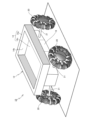
- FIG. 1 is a perspective view schematically showing a moving body according to one embodiment
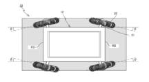
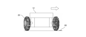
- FIG. FIG. 3 is a plan view of a moving body; It is a front view (a figure seen from the front) of a mobile.
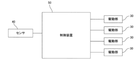
- 3 is a block diagram showing the configuration of a control system of a moving object
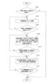
- FIG. 4 is a flow chart showing a processing algorithm executed by the CPU of the control device when implementing the first method
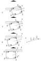
- FIGS. 6A to 6E are diagrams for explaining the first method.
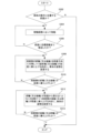
- FIG. 10 is a flow chart showing a processing algorithm executed by the CPU of the control device when implementing the second method
- FIGS. 8A to 8E are diagrams for explaining the second method.
- FIG. 11 is a flow chart showing a processing algorithm executed by the CPU of the control device when implementing the third method
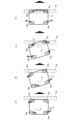
- FIG. FIGS. 10A to 10D are diagrams for explaining the third method.
- FIG. 1 schematically shows a perspective view of a mobile body 10 according to one embodiment
- FIG. 2 shows a plan view of the mobile body 10
- FIG. 3 shows a front view of the mobile body 10. (view from the front) are shown, respectively.
- the moving body 10 includes a vehicle body 12, four omnidirectional wheels 20 that support the vehicle body 12, and four driving units 30 that individually rotate and drive the four omnidirectional wheels 20 (not shown in FIG. 1, see FIG. 4). , a control device (not shown in FIG. 1, see FIG. 4) that controls the traveling of the moving body 10 by controlling sensors 40 (not shown in FIG. 1, see FIG. 4) mounted on the vehicle body and four driving units 30 ) 50, etc.
- an omnidirectional wheel (hereinafter also referred to as a wheel or drive wheel as appropriate) 20 is positioned along the circumference of a circle (having a radius smaller than the radius of the wheel) centered on the axle 21 of the omnidirectional wheel.
- a plurality of rotating bodies small wheels, for example, rollers
- the outer peripheral surface of each of the plurality of rotating bodies is arranged along the outer peripheral surface of the wheel. Movement of the wheel 20 in the direction perpendicular to the axle due to rotation about the axle 21 and movement of the wheel 20 in the direction parallel to the axle due to rotation of the rotating body are appropriately combined.
- the wheels 20 can move in all directions on the contact surface.
- an omnidirectional wheel is used as an example in this embodiment.
- the omnidirectional wheels 20 are not limited to omni wheels.
- the moving body 10 moves while rotating one or more of the four omniwheels (about the axle 21).
- the shape and configuration of the vehicle body 12 are not particularly limited.
- the use of the moving body 10 is not particularly limited.
- the vehicle body 12 has two parts: a main body part 14 having a thin rectangular parallelepiped outer shape and a motor housing part 16 integrally provided therebelow. ing.
- the main body 14 is, for example, a bottomed hollow member that is rectangular in plan view and has a rectangular top opening.
- a lid member 14c is inserted from above into the rectangular opening 14b of the body portion 14 .
- An elongated octagonal (oval or rectangular) opening (not shown) is formed in the front-rear direction of the vehicle body 12 (horizontal direction in FIG. 2) at the bottom of the main body 14, and a lid member 14c closes the opening. are placed.
- the motor housing portion 16 is an octagonal bottomed hollow member integrally provided on the lower surface of the main body portion 14 in a state surrounding the opening of the bottom portion of the main body portion 14 from below.
- Each of the four omniwheels 20 is connected to four drive units 30 (not shown in FIGS. 1 to 3, see FIG. 4) provided inside the motor housing unit 16, respectively.
- the four omniwheels 20 and the driving section 30 may be rigidly connected to the motor housing section 16, or may be flexibly connected via springs. In the latter case, a plurality of omniwheels 20 and drive units 30 may be integrally and flexibly connected, or four may be separately and flexibly connected (that is, four-wheel independent suspension).
- Each of the four driving units 30 has the same structure, and is mainly composed of motors having the same performance.
- the axles 21 of the four omniwheels 20 are respectively connected to the shafts of the motors of the four drive units 30 via couplings.
- Each of the four drive units 30 may have a non-excitation type brake as a brake. Further, each of the four drive units 30 may or may not have a speed reducer. Although not shown in FIGS. 1, 2, etc., all or part of the control device 50 that controls the driving of the drive unit 30 is mounted on the vehicle body 12. As shown in FIG. Also, a battery or the like that supplies electric power to the drive unit 30 may be mounted on the vehicle body 12 . Also, the drive unit 30 may be of any type as long as it can drive the omniwheel 20 .
- the motor accommodating portion 16 is actually formed with a plurality of heat exhaust openings (not shown) for releasing the heat generated by the motor to the outside.
- the motor housing portion 16 is not limited to a hollow member. Also good. For example, a four-wheel independent suspension configuration in which four separate housings (boxes) of the motor housing section 16 are provided and these housings are flexibly supported by springs may be employed.
- the four omniwheels 20 are attached to the vehicle body 12 in order to make the component force in the longitudinal direction of the resultant force of the propulsive force generated by the maximum generated torque of the four omniwheels 20 larger than the component force in the lateral direction.
- the angle ⁇ is set to about 15° as shown in FIG.
- reference numerals FB and RB indicate the front end and rear end of the vehicle body 12, respectively.
- the mounting angles .theta. of the four wheels are all set to be the same, but the present invention is not limited to this.
- the propulsive force generated by the wheels is actually determined by the torque generated by the wheels and the coefficient of dynamic friction between the wheels and the contact surface. It is assumed that the propulsive force (driving force) is generated by the wheels, and detailed description of the generation of the propulsive force is omitted. Further, hereinafter, the driving force generated by each of the four driving wheels 20, the resultant force of the driving forces generated by two or more driving wheels 20, or their component force in any direction will be referred to as the driving force for convenience. . Each wheel 20 generates a driving force (driving force) in a direction parallel to the axle 21 by rotating the small wheel.
- the step 60 may not be overcome by linear movement to the left as indicated by the white arrow.
- the constant height is determined by the size relationship between the diameter of the rotating body (roller, etc.) of the omniwheel 20 and the height of the step 60, the motor torque, the angle ⁇ , and the like.
- a step usually means a difference in height on a road surface such as a road. It includes not only the convex portion of the width but also the boundary portion between the low road surface and the uphill slope continuing to the road surface.
- a cable cover (wiring molding) having an arcuate cross section orthogonal to the longitudinal direction corresponds to the stepped portion of the present embodiment.
- the step may be, for example, a braille block.
- a step 60 that is above a certain height and is difficult to overcome by only linear movement to the side of the moving body will be taken up.
- the moving body 10 can move in any direction (inside the horizontal plane) on the road surface.
- FIG. 4 is a block diagram showing the configuration of the control system of the moving body 10. As shown in FIG. The control system in FIG. 4 is configured around a control device 50 .
- the control device 50 includes a CPU (Central Information Processing Unit), a read-only memory (ROM) that holds programs that run on the CPU, and a random access memory (RAM) that also functions as a work area for the CPU. ) and other general-purpose computers.
- the control system includes a sensor 40 connected to a control device 50, four drive units 30, and the like.
- the sensor information output from the sensor 40 is input to the control device 50 .
- the control device 50 individually controls the operations of the four drive units 30 based on the movement route information (how to acquire the movement route will be described later) and sensor information.
- the control device 50 appropriately rotates each of the four omniwheels 20 by individually controlling the operations of the four driving units 30 based on the movement route information and the sensor information, thereby moving the moving body 10 control the running behavior of the
- the sensor 40 is mounted on the vehicle body 12, and in this embodiment, an Intel RealSense 3D camera (trade name) is used as an example.
- This 3D camera includes an RGB camera, an infrared camera, and the like, and by capturing an image of the surroundings, it is possible to obtain not only conventional color information but also depth information, thereby enabling three-dimensional recognition.
- the sensor 40 other 3D cameras, radar ranging sensors capable of measuring the distance to surrounding objects, wireless communication devices that detect surrounding conditions by performing wireless communication with surrounding devices, etc., It is possible to use a pressure-sensitive sensor for detecting contact, a sensor for reading landmarks (markings) on the floor, and the like.
- the sensor 40 detects the surrounding conditions in the moving direction of the mobile body 10 and outputs sensor information.
- the sensor information includes, for example, both the result of measuring the distance to surrounding objects and the result of capturing an image of the surroundings.
- a plurality of types of sensors may be provided as the sensor 40 .
- the control device 50 includes a storage unit that stores map information, step information, and the like, and a processing unit that acquires movement routes, acquires sensor information, makes various judgments, controls the driving unit, and performs other processing.
- Map information and step information are preferably stored in a non-volatile recording medium such as a ROM, but may be stored in a volatile recording medium such as a RAM.
- Acquired information and/or generated information including acquired information is stored in a storage medium such as ROM and RAM.
- the process of storing information, etc. on a recording medium is not limited to a specific one.
- information or the like may be stored in the recording medium via a recording medium, or information or the like input via a communication line or the like or information input via an input device may be stored in the recording medium. It may be so arranged that it is stored by
- the map information is map information related to the area in which the moving body 10 moves, and is used to acquire the movement route described later.
- the CPU of the control device 50 may perform either route calculation by the node search method or route calculation by the state space search method when acquiring the movement route.
- the map information includes the nodes and links used in the node search. It may be map information in a format that allows node search.
- the map information may be information indicating the movable area of the moving body 10 .
- the map information indicating the movable area is information that can distinguish between an area in which the mobile body 10 can move and an area in which the mobile body 10 cannot move.
- the map information may be considered to be map information indicating pillars, walls, and the like, for example.
- the step information is step information of the area where the moving object 10 moves, and includes information about the position of the step in the area where the moving object 10 moves.
- the step information is information indicating the position of the step, the height from the moving road surface, the width, and the like. For example, it may be the terrain (information such as height and inclination) in the moving area, or it may indicate whether or not the moving object 10 can climb over it (for example, whether the height is less than a predetermined threshold). May contain information.
- As the step information only information related to steps that the moving object 10 can climb over may be included. It should be noted that it is also possible to regard a step as a kind of obstacle.
- the step information may be included in the sensor information output from the sensor 40, may be included in the map information, or may be included in both the sensor information and the map information. In this embodiment, for ease of explanation, it is assumed that step information is included in sensor information. Note that the step information included in the sensor information may include information about the relative distance (positional relationship) between the step and the moving object 10 . Instead of acquiring the relative distance between the moving body 10 and the step by the sensor 40, for example, based on the map information and the position information (current position) of the moving body 10, the relative positional relationship between the moving body 10 and the step You can get information.
- the CPU of the control device 50 acquires the movement route of the moving body 10.
- acquisition means acceptance of information input from an input device such as a keyboard, mouse, or touch panel, reception of information transmitted via a wired or wireless communication line, optical disk, magnetic disk, semiconductor memory, etc. It is a concept including obtaining information by receiving information read from a recording medium such as . Acquiring may include generating information by processing information.
- the CPU generates a moving route of the moving object 10 . For example, the CPU may generate a moving route based on information input by the user.
- the CPU may generate the movement route based on the map information and the positional information of the departure point and the positional information of the destination of the moving body 10 input by the user.
- As the positional information of the departure point and the positional information of the destination for example, information transmitted from an external device may be used, or the CPU may calculate these positional information based on predetermined conditions. You can do it. Further, for example, the CPU may generate a movement route based on the map information, the position information of the current value, and the position information of the destination.
- the CPU may use map information in which nodes and links are set in advance and may search for a moving route using various known algorithms. .
- a moving route connecting predetermined nodes is obtained.
- map information indicating the movable area of the moving body 10 may be used to search for the movement route using various known algorithms.
- a movement route is obtained so as to avoid obstacles in a space in which nodes and the like are not set in advance.
- the CPU may generate a route including direction information so that the front end of the moving body 10 faces the movement direction.
- the CPU may, for example, obtain the route by calculating the route, or by transmitting a route calculation instruction to a server or the like that calculates the route and receiving the route calculation result in response to the transmission. You can get the route. In the present embodiment, it is assumed that the route is generated by the CPU in the former case.
- the CPU acquires sensor information regarding the surrounding situation in the moving direction of the moving body 10 detected by the sensor 40 provided on the moving body 10 .
- the CPU determines whether or not there is a step in the moving direction of the moving body 10 .
- the CPU determines whether or not there is a step in the moving direction of the moving body 10 based on the acquired moving route and the step information included in the sensor information. By using such sensor information, it is possible to determine whether or not there is a step based on the actual surrounding conditions of the moving body 10 . Note that the CPU determines whether there is a step when the moving body 10 actually approaches the step by a predetermined distance, but the present invention is not limited to this.
- the CPU may determine whether there is a step in the moving direction of the moving body 10 based on step information included in the map information instead of the acquired sensor information. Also, the presence or absence of a step may be determined based on both map information and sensor information. Here, if there is a difference between the level difference information included in the map information and the level difference information acquired by the sensor 40, the level difference information included in the map information is updated based on the level difference information acquired by the sensor 40. Also good.
- the sensor information is used to determine whether there is a step. For example, information on at least one of the height of the step and the positional relationship with the step may be used for drive control of the moving body 10 .
- the CPU controls the running motion of the moving body 10 by driving the four drive units 30 and controlling the rotation of the four omniwheels 20 .
- the CPU controls each of the four drive units 30 so that the moving object 10 moves along the obtained moving route. That is, the CPU controls each of the four drive units 30 so that the moving body 10 moves along the acquired moving route.
- the CPU may be configured to acquire the current position and the attitude of the moving body 10 and move the moving body 10 while dynamically determining the movement direction.
- a sensor that acquires at least one of the current position and orientation of the moving body 10 may be configured integrally with the sensor 40 or may be provided separately from the sensor 40 .
- the CPU controls the rotation of each of the four omniwheels 20 by driving the four driving units 30, respectively, thereby adjusting the orientation of the vehicle body 12 (moving body 10), that is, the posture of the vehicle body 12 (moving body 10) with respect to the movement direction. set.
- the rotational drive states of the four omniwheels 20 are controlled via the four driving units 30 so that the four omniwheels 20 ride on the step 60 one by one.
- a method for overcoming a side step (steps on one of the right and left sides of the vehicle body 12) 60 of the moving body 10 according to the present embodiment, in which such an omni-wheel drive control method is adopted A specific example will be used for explanation.
- each of the four omniwheels 20 will be referred to as a right front wheel 20a, a right rear wheel 20b, a left front wheel 20c, and a left rear wheel 20d according to the mounting position with respect to the vehicle body 12.
- the drive units that rotationally drive the right front wheel 20a, right rear wheel 20b, left front wheel 20c, and left rear wheel 20d are referred to as drive units 30a, 30b, 30c, and 30d, respectively.
- the case of getting over a step 60 existing on the left side of the vehicle body 12 will be described.
- This first method is one aspect of a method in which two or more wheels are not allowed to climb over a step at the same time, and the wheels are climbed one by one by a combination of vehicle body rotation and straight movement. Specifically, the vehicle body is rotated so that the small wheels (rollers, rotating bodies) of the front wheels on the side of the step do not slip easily, and then the vehicle body moves linearly to ride on the step one by one (step climb).
- FIG. 5 is a flow chart showing the processing algorithm executed by the CPU in implementing the first method.
- step S102 it is determined whether the step is located on the side (right side or left side) of the vehicle body. If the determination in step S102 is negative, the step is located forward or rearward in the direction of travel, and the processing of this routine ends.
- step S102 determines whether the vehicle body 12 (moving body 10) is moving along the movement route until it approaches the step 60 to the target distance (steps S104, S106).
- the target distance is, for example, a predetermined distance for bringing the vehicle body 12 closer to the step 60 at a sufficient level.
- the movement is performed by the CPU controlling at least one of the drive units 30a to 30d based on information on the movement route and sensor information from the sensor 40 to control the front right wheel 20a, the rear right wheel 20b, and the left wheel. This is done by rotating at least one of the front wheel 20c and the left rear wheel 20d.
- FIG. 6A shows the vehicle body 12 (moving body 10) when approaching the step 60 located on the left side (one side) of the vehicle body 12 to the target distance.
- steps S108 and S110 the vehicle body 12 is rotated until the front wheel 20c on the side of the step 60 becomes parallel to the step 60, that is, until the small wheel (rotating body, roller) of the front wheel 20c on the side of the step 60 assumes a posture that makes it difficult to slip. is slightly driven forward, the front wheel 20c on the side of the step is directed in a direction parallel to the step to change the attitude of the vehicle body.
- FIGS. 6A and 6B show an example of posture change performed in steps S108 and S110.
- the left rear wheel 20d (the rear wheel on the side of the step) generates a driving force of a predetermined magnitude, and the driving force greater than that of the left rear wheel 20d is generated by the right front wheel 20a (the side of the step).
- the front wheels on the opposite side drive the vehicle body 12 in the direction of those driving forces, and generate a counterclockwise moment (for example, about the centroid) according to the difference between the two driving forces.
- the orientation of the vehicle body 12 is changed by rotating the vehicle body 12 to the left.
- the thrust of the left rear wheel 20d is made equal to the thrust of the right front wheel 20a.
- the front left wheel 20c (the front wheel on the side of the step) becomes parallel to the step 60 as shown in FIG. 6B, and the front left wheel 20c is pressed against the step.
- step S110 When the state shown in FIG. 6B is reached, the determination in step S110 is affirmative, and in steps S112 and S114, the posture is maintained until all four omniwheels 20 get over the step, and the predetermined position is reached. Move linearly to one side (left side) at speed (speed at which necessary and sufficient torque is generated).
- FIGS. 6(C) and 6(D) show how the vehicle body 12 changes position due to movement according to the loop processing of steps S112 and S114. As shown in these figures, the movement here involves moving the vehicle body 12 to the left with all of the right front wheel 20a, the right rear wheel 20b, the left front wheel 20c, and the left rear wheel 20d via the drive units 30a to 30d.
- vector AB+vector BC vector AC shown in FIG.
- the vehicle body 12 linearly moves to one side (left side).
- Vector AB magnitude 2F
- vector BC magnitude 2F
- a resultant force of driving force F is shown, and vector AC represents a resultant force of vector AB and vector BC.
- the vehicle body 12 moves in the direction of the resultant force AC (that is, leftward).
- step S114 the determination in step S114 is affirmative, and the series of processes of this routine ends.
- 6(A) to 6(D) illustrate the case where the left front wheel 20c, the left rear wheel 20d, the right front wheel 20a, and the right rear wheel 20b are sequentially driven over the step 60 one by one. However, as shown in parentheses in some steps of the flow chart of FIG. It's okay to get over it.
- This second method is another aspect of the method in which two or more wheels are not allowed to climb over a step at the same time, and the wheels are climbed one by one by a combination of vehicle body rotation and straight movement. . Specifically, the vehicle body is rotated so that the small wheels (rollers, rotating bodies) of the front wheels on the side of the step do not slip easily, and then the vehicle body moves linearly to ride on the step one by one (step climb).
- FIG. 7 is a flow chart showing the processing algorithm executed by the CPU in implementing the second method.
- step S202 it is determined whether or not the step is located on the side (right side or left side) of the vehicle body. If the determination in step S202 is negative, the step is located forward or rearward in the direction of travel, and the processing of this routine ends.
- step S202 determines whether the vehicle body 12 (moving body 10) continues to move along the movement route until it approaches the step 60 to the target distance (steps S204, S206).
- the target distance is, for example, a predetermined distance for bringing the vehicle body 12 closer to the step 60 at a sufficient level.
- the movement is performed by the CPU controlling at least one of the drive units 30a to 30d based on information on the movement route and sensor information from the sensor 40 to control the front right wheel 20a, the rear right wheel 20b, and the left wheel. This is done by rotating at least one of the front wheel 20c and the left rear wheel 20d.
- FIG. 8A shows the vehicle body 12 (moving body 10) when approaching the step 60 located on the left side (one side) of the vehicle body 12 to the target distance.
- steps S208 and S210 the vehicle body 12 is moved until the front wheel 20c on the side of the step 60 becomes parallel to the step 60, that is, until the small wheel (rotating body, roller) of the front wheel 20c on the side of the step 60 assumes a difficult-to-slip posture.
- the front wheel 20c on the side of the step 60 is directed in a direction parallel to the step, and the posture of the vehicle body to change
- FIGS. 8A and 8B show an example of posture change performed in steps S208 and S210.
- the left rear wheel 20d (rear wheel on the step side) generates a driving force of a predetermined magnitude, and the driving force larger than the left rear wheel 20d is applied to the right front wheel 20a (step difference side rear wheel). and the front wheels on the opposite side), and drives the vehicle body 12 in the direction of those driving forces, and generates a counterclockwise moment (for example, centered on the centroid) according to the difference between the two driving forces.
- the direction of the vehicle body 12 is changed by rotating the vehicle body 12 to the left by pressing.
- the driving force of the left rear wheel 20d is made equal to the driving force of the right front wheel 20a.
- step S210 the determination in step S210 is affirmative, and in steps S212 and S214, all the four omniwheels 20 maintain their attitudes until they get over the step and rotate at a predetermined speed (speed at which necessary and sufficient torque is generated). Move forward (or backward) in a straight line.
- FIGS. 8(B) to 8(D) show how the vehicle body 12 changes position due to movement according to the loop processing of steps S212 and S214.
- the movement here generates driving force of the same magnitude F1 (F1 may be the maximum magnitude Fmax ) at both the right front wheel 20a and the left rear wheel 20d,
- Vector DE (magnitude 2F1) represents the resultant force of driving forces (magnitude F1) generated by the front right wheel 20a and rear left wheel 20c
- vector EF magnitude 2F2
- vector DE indicates the resultant force of vector DE and vector EF.
- the vehicle body 12 moves in the direction of the resultant force EF (that is, forward).
- step S214 the determination in step S214 is affirmative, and the series of processes of this routine ends.
- 8(A) to 8(D) illustrate the case where the left front wheel 20c, the left rear wheel 20d, the right front wheel 20a, and the right rear wheel 20b are sequentially driven over the step 60 one by one.
- FIG. It is also possible to sequentially climb over the steps 60 while moving backward.
- This third method is one aspect of the method of climbing one wheel at a time by a combination of counterclockwise and clockwise rotations of the vehicle body without attempting to get over two or more wheels at the same time on a step. is. Specifically, while applying force toward the step, while rotating the vehicle body in the counterclockwise direction and the clockwise direction, the wheels are run on the step one by one (the step is climbed).
- FIG. 9 is a flow chart showing the processing algorithm executed by the CPU in implementing the third method.
- step S302 it is determined whether the step is located on the side (right side or left side) of the vehicle body. If the determination in step S302 is negative, the step is located forward or rearward in the direction of travel, and the processing of this routine ends.
- step S302 determines whether the vehicle body 12 (moving body 10) continues to move along the movement route until it approaches the step to the target distance (steps S304, S306).
- the target distance is, for example, a predetermined distance for bringing the vehicle body 12 closer to the step 60 at a sufficient level.
- the movement is performed by the CPU controlling at least one of the drive units 30a to 30d based on information on the movement route and sensor information from the sensor 40 to control the front right wheel 20a, the rear right wheel 20b, and the left wheel. This is done by rotating at least one of the front wheel 20c and the left rear wheel 20d.
- FIG. 10A shows the vehicle body 12 (moving body 10) approaching the step 60 located on the left side (one side) of the vehicle body 12 to the target distance.
- steps S308 and S310 the posture of the vehicle body is changed so that the front wheel on the step side runs over the step while urging the vehicle body in the direction of the step until the front wheel on the step side runs over the step.
- FIGS. 10A and 10B show an example of posture change performed in steps S308 and S310.
- the rear left wheel 20d (rear wheel on the side of the step) generates a predetermined amount of rearward driving force
- the front right wheel 20a and the rear right wheel 20b (on the side opposite to the step) are generated.
- the front and rear wheels) generate forward driving force of the same magnitude as the left rear wheel 20d.
- the left front wheel 20c (the front wheel on the side of the step) is pushed toward the step 60 by the component of the driving force generated by the right rear wheel 20b (the rear wheel on the side opposite to the step) in the direction toward the centroid of the vehicle body 12.
- the vehicle body 12 While exerting force, the vehicle body 12 is rotated to the left by generating a counterclockwise moment (for example, centered on the center of gravity) by driving forces respectively generated by the left rear wheel 20d, the right front wheel 20a, and the right rear wheel 20b. to change the direction of the vehicle body 12.
- step S310 the determination in step S310 is affirmative, and step S312 and step S312 are executed.
- step S314 the direction of the vehicle body is changed until the rear wheel on the side of the step (left rear wheel 20d) runs over the step 60 and the direction of the vehicle body 12 becomes parallel to the step.
- FIGS. 10(C) and 10(D) show how the position of the vehicle body 12 changes due to movement according to the loop processing of steps S312 and S314.
- the movement here is that the rear wheel (right rear wheel 20b) on the opposite side of the step 60 and the front wheel (left front wheel 20c) on the step are of the same size but opposite to each other.
- the remaining two driving wheels (the right front wheel 20a and the left rear wheel 20d) generate driving forces in the same direction (forward direction) smaller than these driving forces.
- the vehicle body 12 rotates clockwise due to the clockwise moment generated by the driving forces respectively generated by the right rear wheel 20b and the left front wheel 20c, and the resultant force of the driving forces generated by the right front wheel 20a and the left rear wheel 20d.
- the left front wheel 20c is prevented from slipping down the step during the posture change.
- FIG. 10(D) shows a state in which all the driving wheels 20a to 20d shift to a mode in which the vehicle body 12 is moved leftward at a predetermined speed immediately after the determination in step S314 is affirmative.
- the vehicle body 12 is rotated to the right and then to the left.
- the moving body 10 moves along the moving path, but the moving path is set so as to continue leftward movement. If so, after moving a predetermined distance in the left direction along the movement path, in the same procedure as the third method described above, rotate the vehicle body to the left (or right) and then to the right (or to the left).
- the right front wheel 20a and the right rear wheel 20b may be sequentially caused to climb over the step 60 one by one.
- the mobile body 10 and the travel control method thereof it is possible to respond to the desire to move quickly in a predetermined uniaxial direction (usually, in the longitudinal direction of the vehicle body), and to move the body in a straight line. Even if the step 60 is difficult to get over only by moving, it becomes possible to get over it by getting over it one by one.
- the information on the movement route acquired as described above is used.
- the obtained information may be used as movement route information.
- the sensor 40 can acquire the presence or absence of a step, the height of the step, the relative positional relationship (distance) between the moving body 10 and the step, and the like.
- a sensor may be used to acquire the height of the step (including the presence or absence of the step) and the relative positional relationship between the moving body 10 and the step.
- the information about the height of the step may include at least one of the width, length, extending direction, and the like of the step.
- the above-described first to third methods are examples of the travel control method when the moving body 10 climbs over a step on the side, and the travel control method when the moving body 10 climbs over a step according to the present embodiment is these. is not limited to For example, in the flowchart of FIG. 5 used to describe the first method described above, when the movement of the moving body 10 in step S104 is movement in the forward direction, the operation in step S108 is performed by at least four omniwheels 20. It is possible to start without making the forward direction component of one generated driving force zero (see FIG. 6(A)). In the case of FIG. 6A, the components in the forward direction of the drive forces generated by the right front wheel 20a and the left rear wheel 20d need not be zero.
- step S108 is made to zero the backward component of the driving force generated by the left front wheel 20c and the right rear wheel 20b. (see description "(or backward)" in step S108).
- the movement of the moving body 10 in step S104 may be lateral movement toward the step 60 or movement in the rotational direction. It is possible to start at least one of the two omniwheels 20 without zeroing the component of the driving force generated in its direction of travel. As can be seen by comparing the flow chart of FIG. 5 with the flow charts of FIGS.
- the same as the above embodiment is performed.
- the limit height of the step that can be climbed is higher. be able to overcome.
- the first omni wheel 20 that rides on the step first runs on the step so that the first omni wheel 20 is parallel to the step (that is, the small wheels of that omni wheel 20 are perpendicular to the step). If the rotational drive state of the four omniwheels 20 is controlled to start with the orientation of the vehicle body 12, the highest step can be climbed.
- the mounting angle ⁇ (the angle ⁇ shown in FIG. 2) of the four omniwheels 20 with respect to the vehicle body 12 is set to about 15 degrees as an example, but the mounting angle ⁇ is not limited to this, and may be 45 degrees. A smaller angle is better.
- the mounting angle ⁇ is more preferably about 10 degrees or more and 35 degrees or less.
Landscapes
- Engineering & Computer Science (AREA)
- Power Engineering (AREA)
- Transportation (AREA)
- Mechanical Engineering (AREA)
- Control Of Position, Course, Altitude, Or Attitude Of Moving Bodies (AREA)
Abstract
4つの駆動部によって個別に回転駆動される4つのオムニホイール(20a~20d)によって走行面内の全方向に駆動される移動体は、4つのオムニホイールで発生する最大駆動力の前後方向の分力が最大駆動力の左右方向の分力より大きくなるような角度で、左右の前輪及び後輪が、車体にそれぞれ取り付けられており、その移動体の走行制御方法は、段差(60)を乗り越えるに際して、4つのオムニホイールを1輪ずつ段差(60)に乗り上げるように、4つのオムニホイールの回転駆動状態を制御することを含む。
Description
本発明は、走行制御方法及び移動体に係り、さらに詳しくは、4つの全方向移動車輪によって支持された車体を有し、4つの全方向移動車輪によって走行面内の全方向に駆動される移動体の走行を制御する走行制御方法及び車体を走行面内の全方向に駆動する4つの全方向移動車輪から成る左右の前輪及び後輪を備える移動体に関する。
従来、複数のオムニホイール(登録商標)を備える移動体が知られている。この種の移動体においては、移動体が移動する路面上に段差があると、段差進入時の移動体の姿勢によっては、オムニホイールの段差への引っかかりが生じることがある。
かかる不都合に対処するため、判断部により移動体の移動方向において段差があると判断された場合に、複数のオムニホイールの全てを回転させて移動方向に移動体を移動させ、移動体を段差に進入させる回転制御部を備える制御装置と、該制御装置の制御に応じて前記複数のオムニホイールのそれぞれを回転させる駆動部と、を備える移動体」に関する提案が、最近なされている(例えば、特許文献1参照)。
特許文献1には、車軸が互いに直交している4つのオムニホイールの全てを駆動して段差を乗り越えることが開示されている。具体的には特許文献1の図6に、4つのオムニホイールが円周上に等間隔に(90°間隔で)配置された移動体が、互いに車軸が直交する4つの駆動輪の全ての向きが、段差に対して45°を成す状態で、段差を乗り越えることが開示されている。
しかるに、無人搬送車(Automatic Guided Vehicle)などの移動体では所定の一軸方向に速く動かしたいという要望があるが、特許文献1に開示される移動体は、このような用途には適していない。また、特許文献1では、進行方向の前方以外の方向に存在する段差を乗り越える際には、移動体を一旦停止して方向転換する必要がある。
この一方、4つのオムニホイールなどの全方向移動車輪の車体に対する角度が45°より小さくなるように車軸の取り付け角度を変更すれば、一方向、例えば前後方向に速く動かすことは可能になるが、取り付け角度によっては左右方向の推進力の分力が小さくなって車体の側方にある段差を乗り越えることが困難になる。
本発明の第1の態様によれば、モータをそれぞれ有する4つの駆動部によって個別に回転駆動される4つの全方向移動車輪によって支持された車体を有し、前記4つの全方向移動車輪によって走行面内の全方向に駆動される移動体の走行を制御する走行制御方法であって、前記4つの全方向移動車輪で発生する最大駆動力の前後方向の分力が前記最大駆動力の左右方向の分力より大きくなるような角度で、前記4つの全方向移動車輪から成る左右の前輪及び後輪が、前記車体にそれぞれの車軸を介して取り付けられており、段差を乗り越えるに際して、前記4つの全方向移動車輪を1輪ずつ前記段差に乗り上げるように、前記4つの全方向移動車輪の回転駆動状態を制御することを含む走行制御方法が、提供される。
本発明の第2の態様によれば、車体を走行面内の全方向に駆動する4つの全方向移動車輪から成る左右の前輪及び後輪を備える移動体であって、前記4つの全方向移動車輪のそれぞれの車軸を個別に回転駆動するモータをそれぞれ有する4つの駆動部と、前記車体の移動方向における周囲の状況を検知してセンサ情報を出力するセンサと、移動経路の情報と前記センサ情報とに基づいて、前記4つの駆動部を介して前記4つの全方向移動車輪の駆動を制御することで、前記移動体の走行を制御する制御装置と、を備え、前記4つの全方向移動車輪で発生する最大駆動力の前後方向の分力が前記最大駆動力の左右方向の分力より大きくなるような角度で、前記左右の前輪及び後輪が、前記車体にそれぞれの車軸を介して取り付けられており、前記制御装置は、前記移動経路の情報と前記センサ情報とに基づいて段差を確認したとき、前記段差を乗り越えるに際して、前記4つの全方向移動車輪を1輪ずつ前記段差に乗り上げるように、前記4つの全方向移動車輪の回転駆動状態を前記4つの駆動部をそれぞれ介して制御する移動体が、提供される。
以下、一実施形態について、図1~図10に基づいて説明する。
図1には、一実施形態に係る移動体10が斜視図にて概略的に示され、図2には、移動体10の平面図が示され、図3には、移動体10の正面図(前方から見た図)が、それぞれ示されている。
図1には、一実施形態に係る移動体10が斜視図にて概略的に示され、図2には、移動体10の平面図が示され、図3には、移動体10の正面図(前方から見た図)が、それぞれ示されている。
移動体10は、車体12、車体12を支持する4つの全方向移動車輪20、4つの全方向移動車輪20を個別に回転駆動する4つの駆動部30(図1では不図示、図4参照)、車体に搭載されたセンサ40(図1では不図示、図4参照)及び4つの駆動部30を制御して、移動体10の走行を制御する制御装置(図1では不図示、図4参照)50、等を備えている。
ここで、全方向移動車輪(以下、適宜、車輪又は駆動輪とも呼ぶ)20は、その全方向移動車輪の車軸21を中心とする円(車輪の半径より小さい半径を有する)の円周に沿って配置された軸を中心にそれぞれ回転する回転体(小輪、例えばローラなど)が、車軸21周りに複数配置され、その複数の回転体それぞれの外周面が車輪の外周面に沿って配置されるように構成された回転体付き車輪であり、車軸21を中心とする回転による車軸直交方向への車輪20の移動と回転体の回転よる車軸平行方向への車輪20の移動とが適宜組み合わされることにより、車輪20の接地面における全方向への移動が可能となっている。全方向移動車輪20としては、本実施形態では、一例としてオムニホイールが用いられているので、以下、全方向移動車輪20をオムニホイール20とも表記する。ただし、全方向移動車輪20は、オムニホイールに限られるものではない。
移動体10は、4つのオムニホイールの1つ以上を(車軸21を中心として)回転させながら移動する。なお、本実施形態に係る移動体10は、4つのオムニホイール20を用いて移動するものであれば、車体12の形状、構成などは特に問わない。また、移動体10の用途なども特に問わない。
一例として、車体12は、図1に示されるように、厚さの薄い直方体状の外形を有する本体部14と、その下方に一体的に設けられたモータ収容部16との2部分を有している。
本体部14は、一例として、上面が矩形に開口した平面視矩形の有底の中空部材から成る。本体部14の矩形開口14bの内部には上方から蓋部材14cが挿入されている。本体部14の底部には、車体12の前後方向(図2の左右方向)に細長い八角形(楕円形あるいは矩形)の開口(不図示)が形成されおり、該開口を塞ぐように蓋部材14cが配置されている。
モータ収容部16は、本体部14底部の開口を下方から取り囲む状態で本体部14の下面に一体的に設けられた平面視(上方から見て)八角形の有底の中空部材から成る。
4つのオムニホイール20それぞれは、モータ収容部16の内部に設けられた4つの駆動部30(図1~図3等では不図示、図4参照)にそれぞれ接続されている。ここで、4つのオムニホイール20と駆動部30は、モータ収容部16に剛に接続されていても良いし、バネを介して柔に接続されていても良い。後者の場合に複数のオムニホイール20と駆動部30が一体となって柔に接続されていても良いし、4つが別々に柔に接続(すなわち、4輪独立懸架)されていても良い。4つの駆動部30のそれぞれは、同一構造を有しており、同一性能を有するモータを中心として構成されている。4つのオムニホイール20それぞれの車軸21は、4つの駆動部30それぞれのモータの軸にカップリングをそれぞれ介して接続されている。4つの駆動部30それぞれは、ブレーキとして無励磁作動形ブレーキを有していても良い。また、4つの駆動部30それぞれは、減速機を備えていても良いし、備えていなくても良い。なお、図1、図2等では図示していないが、駆動部30の駆動を制御する制御装置50の全部又は一部は、車体12に搭載されている。また、駆動部30に電力を供給するバッテリー等が、車体12に搭載されていても良い。また、駆動部30は、オムニホイール20を駆動できるものであれば、どのようなものであっても良い。
なお、モータ収容部16には、実際には、モータの発熱を外部に逃がすための排熱用の開口(不図示)が複数形成されている。また、モータ収容部16は中空部材に限られるものではなく、例えば本体部14の下面に設けられた複数本の支持部材によって吊り下げられた板部材を含むフレーム構造によってモータ収容部を構成しても良い。例えば、モータ収容部16のハウジング(箱)が4つ別々にあり、それらのハウジングをバネで柔に支持する、4輪独立懸架の構成であっても良い。
移動体10では、4つのオムニホイール20の最大発生トルクによる推進力の合力の前後方向の分力を、その左右方向の分力に比べて大きくするために、4つのオムニホイールの車体12に対する取り付け角度θを、図2に示されるように、15°程度に設定している。これにより、移動体10は、左右方向に比べて前後方向に各段速く走行できる。図2において、符号FB、RBは、車体12の前端、後端を、それぞれ示す。本実施形態では、4輪の取り付け角度θを全て同じに設定しているが、これに限られるものではない。
なお、車輪で発生する推進力は、実際には、車輪の発生トルク及び車輪と接地面との間の動摩擦係数などによって定まるものであるが、本明細書では、回転に伴う車輪の発生トルクによって推進力(駆動力)が、その車輪で発生するものとし、推進力の発生についての詳細は説明を省略する。また、以下においては、4つの駆動輪20それぞれで発生する推進力あるいは2つ以上の駆動輪20で発生する推進力の合力、又はそれらの任意の方向の分力を、便宜上、駆動力と呼ぶ。なお、それぞれの車輪20は、小輪の回転によって、車軸21と平行な方向の推進力(駆動力)を発生する。
ところで、移動体10は、図3の正面図(前方から見た図)に示されるように、移動体10の左側に例えばケーブルカバーなどの段差60があり、その段差60の高さがある一定の高さ以上であると、白抜き矢印で示される左側方への直線的な移動では、その段差60を乗り越えられないことが生じる。ここで、その一定の高さは、オムニホイール20の回転体(ローラなど)の直径と段差60の高さとの大小関係、及びモータトルク、角度θなどによって定まる。なお、段差とは、通常、道路などの路面に出来た高低差を意味するが、本実施形態で問題とする段差60は、移動体10の走行路面上で低い路面より所定高さ以上高い所定幅の凸部は勿論、低い路面と該路面に連続する上り斜面との境界部分をも含む。本実施形態で問題とする段差には、例えば長手方向に直交する断面が円弧状を有するケーブルカバー(配線モール)などが該当する。この他、段差は、例えば点字ブロックなどであっても良い。また、以下の説明では、一定高さ以上で移動体の側方への直線的な移動のみでは乗り越え困難な段差60を取り上げる。
移動体10は、1つ以上のオムニホイール20を同時に駆動させることで、走行路面上のどの方向(水平面内方向)にも移動できる。
移動体10は、1つ以上のオムニホイール20を同時に駆動させることで、走行路面上のどの方向(水平面内方向)にも移動できる。
図4には、移動体10の制御系の構成がブロック図にて示されている。図4の制御系は、制御装置50を中心として構成されている。制御装置50は、CPU(中央情報処理装置)とCPU上で動作するプログラムを保持する役目などを有するリード・オンリ・メモリ(ROM)とCPUのワークエリアとしても機能するランダム・アクセス・メモリ(RAM)などからなる汎用のコンピュータである。
制御系は、制御装置50に接続されたセンサ40及び4つの駆動部30等を備えている。
制御系は、制御装置50に接続されたセンサ40及び4つの駆動部30等を備えている。
制御装置50には、センサ40から出力されたセンサ情報が入力される。また、制御装置50は、移動経路の情報(移動経路の取得方法などについては後述する)とセンサ情報とに基づいて、4つの駆動部30の動作を個別に制御する。換言すると、制御装置50は、移動経路の情報とセンサ情報とに基づいて、4つの駆動部30の動作を個別に制御することにより4つのオムニホイール20のそれぞれを適宜回転させて、移動体10の走行動作を制御する。
センサ40は、車体12に搭載され、本実施形態では、一例としてインテル社のRealSense3Dカメラ(商品名)が用いられている。この3Dカメラは、RGBカメラ及び赤外線カメラ等を含み、周囲の画像を撮影することで、従来の色情報のほかに奥行きの情報を取得でき、3次元での認識が可能である。なお、センサ40としては、その他の3Dカメラ、周囲の物体との距離を測定可能なレーダ測距センサ、周囲の装置等と無線通信を行うことにより周囲の状況を検知する無線通信装置、物体との接触を検知する感圧センサ、床面のランドマーク(マーキング)読み取るセンサなどを用いることが可能である。
センサ40は、移動体10の移動方向における周囲の状況を検知して、センサ情報を出力する。センサ情報は、例えば、周囲の物体までの距離の測定結果及び周囲の画像の撮影結果の両者を含む。センサ40として複数種類のセンサが設けられていても良い。
本実施形態では、制御装置50は、地図情報及び段差情報などを格納する格納部と、移動経路の取得、センサ情報の取得、各種判断、及び駆動部の制御その他の処理を行う処理部との役目を有する。地図情報及び段差情報などはROMなどの不揮発性の記録媒体に記憶すると良いが、RAMなどの揮発性の記録媒体に記憶しても良い。ROM、RAM等の記憶媒体には、地図情報及び段差情報などの取得された情報などを含む、取得された情報及び/又は生成された情報などが格納される。
記録媒体に情報等が記憶される過程は、特定のものに限られない。例えば、記録媒体を介して情報等が記録媒体で記憶されるようになっていても良いし、通信回線等を介して入力された情報等又は入力デバイスを介して入力された情報等が記録媒体で記憶されるようになっていても良い。
地図情報は、移動体10が移動する領域に関する地図情報であり、後述する移動経路の取得に用いられる。制御装置50のCPUは、移動経路の取得に際して、ノード探索法による経路の演算及び状態空間探索法による経路の演算のいずれを行っても良い。例えば、ノード探索法による経路の演算が行われる場合には、地図情報には、ノード探索で用いられるノードやリンクが含まれていることが好適である。ノード探索を行うことができる種類のフォーマットの地図情報であっても良い。また、状態空間探索法による経路の演算が行われる場合には、地図情報は、移動体10の移動可能領域を示す情報であっても良い。移動可能領域を示す地図情報は、ある領域において移動体10が移動できる領域と、移動できない領域とを区別可能な情報であり、例えば、移動体10の移動領域における障害物の領域を示す情報であっても良く、移動体10の移動領域における移動体10が通行可能な領域を示す情報であっても良い。障害物の領域は、例えば、障害物の位置と大きさとによって示されても良く、障害物の境界線や輪郭線によって示されても良い。障害物とは、移動体10が移動する領域に継続的又は一時的に存在する、移動体10の移動の障害となるものであり、例えば、柱や壁、載置物等であっても良い。したがって、その地図情報は、例えば、柱や壁等を示す地図の情報であると考えても良い。
段差情報とは、移動体10が移動する領域の段差情報であり、移動体10が移動する領域における段差の位置に関する情報を含む。段差情報とは、段差の位置、移動路面からの高さ、幅等を示す情報である。例えば、移動する領域にある地形(高低や傾斜などの情報)であっても良いし、移動体10が乗り越えられるか否か(例えば、所定の閾値未満の高さであるか否か)を示す情報が含まれていても良い。段差情報として、移動体10が乗り越えられる段差に関する情報のみが含まれていても良い。なお、段差を、障害物の一種として捉えることも可能である。段差情報は、センサ40から出力されるセンサ情報に含まれるものであっても良く、地図情報に含まれるものであっても良く、あるいは、センサ情報と地図情報の両方に含まれるものでも良いが、本実施形態では、説明を容易にするため、段差情報はセンサ情報に含まれるものとする。なお、センサ情報に含まれる段差情報は、段差と移動体10との相対的な距離(位置関係)に関する情報を含んでも良い。センサ40によって移動体10と段差との相対的な距離を取得する代わりに、例えば地図情報と移動体10の位置情報(現在位置)に基づいて移動体10と段差との相対的な位置関係に関する情報を取得しても良い。
前述したように、制御装置50のCPU(以下、単にCPUと表記する)は、移動体10の移動経路を取得する。本明細書において、取得とは、キーボード、マウス、あるいはタッチパネルなどの入力デバイスから入力された情報の受け付け、有線もしくは無線の通信回線を介して送信された情報の受信、光ディスクや磁気ディスク、半導体メモリなどの記録媒体から読み出された情報の受け付けなどにより情報を得ることを含む概念である。取得には、情報処理を行うことにより情報を生成することが含まれていても良い。本実施形態において、CPUは、移動体10の移動経路を生成する。例えば、CPUは、ユーザから入力された情報に基づいて、移動経路を生成しても良い。CPUは、地図情報と、ユーザから入力された移動体10の出発地の位置情報及び目的地の位置情報とに基づいて、移動経路を生成しても良い。出発地の位置情報、目的地の位置情報としては、例えば、外部の装置から送信されたものを用いるようにしても良いし、所定の条件に基づいて、CPUがこれらの位置情報を算出するようにしても良い。また、例えば、CPUは、地図情報と、現在値の位置情報及び目的地の位置情報とに基づいて、移動経路を生成しても良い。
なお、CPUは、例えばノード探索法によって経路探索を行う場合には、あらかじめノードやリンクの設定されている地図情報を用いて、種々の公知のアルゴリズムを用いて移動経路の探索を行っても良い。ノード探索法では、予め定められたノードをつなげた移動経路が取得されることになる。また、例えば状態空間探索法によって経路探索を行う場合には、移動体10の移動可能領域を示す地図情報を用いて、種々の公知のアルゴリズムを用いて移動経路の探索を行っても良い。状態空間探索法では、あらかじめノード等の設定されていない空間において、障害物を回避するように移動経路が取得されることになる。また、例えば、CPUは、移動体10の前端が移動方向を向くように方向情報を含む経路を生成しても良い。なお、CPUは、例えば、経路を演算することによって取得しても良いし、経路を演算するサーバ等に経路の演算の指示を送信し、その送信に応じて経路の演算結果を受信することによって経路を取得しても良い。本実施形態では、前者の場合、すなわちCPUによって経路の生成が行われるものとする。
また、CPUは、移動体10に設けられているセンサ40により検知された移動体10の移動方向における周囲の状況に関するセンサ情報を取得する。
また、CPUは、移動体10の移動方向における段差の有無を判断する。本実施形態において、CPUは、取得された移動経路と、センサ情報に含まれる段差情報とに基づいて、移動体10の移動方向における段差の有無を判断する。このようなセンサ情報を利用することにより、実際の移動体10の周囲の状況に基づいて段差の有無に関する判断を行うことができる。なお、CPUは、段差有無の判断を、現実に移動体10が段差に所定距離まで近づいたときに段差があると判断するようにしているが、これに限られない。
なお、CPUは、取得されたセンサ情報の代わりに、地図情報に含まれる段差情報に基づいて、移動体10の移動方向における段差の有無を判断しても良い。また、地図情報とセンサ情報の両方に基づいて段差の有無を判断しても良い。ここで、地図情報に含まれる段差情報と、センサ40によって取得される段差情報とに差異がある場合は、センサ40によって取得される段差情報に基づいて地図情報に含まれる段差情報を更新しても良い。なお、本実施形態ではセンサ情報を段差の有無の判断に用いるものとしたが、センサ40によって移動体10と段差との相対的な位置関係に関する情報を取得可能とし、段差の有無の判断以外、例えば移動体10の駆動制御に段差の高さ及び段差との位置関係の少なくとも一方の情報を用いても良い。
さらに、CPUは、4つの駆動部30それぞれを駆動させて4つのオムニホイール20それぞれの回転を制御することにより、移動体10の走行動作を制御する。本実施形態において、CPUは、移動体10が取得された移動経路を移動するように4つの駆動部30のそれぞれを制御する。すなわち、CPUは、取得された移動経路を移動体10が移動するように、4つの駆動部30それぞれを制御する。なお、CPUは、現在位置と移動体10の姿勢とを取得し、動的に移動方向を決定しながら移動体10を移動させるように構成されていても良い。移動体10の現在位置と姿勢との少なくとも一方を取得するセンサは、センサ40と一体に構成しても良いし、センサ40と分離して設けても良い。
CPUは、4つの駆動部30それぞれを駆動させて4つのオムニホイール20それぞれの回転を制御することにより、車体12(移動体10)の向き、すなわち移動方向に対する車体12(移動体10)の姿勢を設定する。
本実施形態では、移動体10では、CPUは、移動経路(算出又は取得した移動経路)の情報とセンサ情報(および/または地図情報に含まれる段差情報)とに基づいて段差を確認したとき、その段差を乗り越えるに際して、4つのオムニホイール20を1輪ずつ段差60に乗り上げるように、4つのオムニホイール20の回転駆動状態を4つの駆動部30をそれぞれ介して制御する。以下、このようなオムニホイールの駆動制御方法が採用された、本実施形態に係る移動体10の側方段差(車体12の右側及び左側の一方の側にある段差)60の乗り超え方法について、具体例を用いて説明する。以下では、説明の便宜上、4つのオムニホイール20のそれぞれを、車体12に対する取り付け位置に応じて右前輪20a、右後輪20b、左前輪20c、左後輪20dと表記し、これに対応して右前輪20a、右後輪20b、左前輪20c、左後輪20dのそれぞれを回転駆動する駆動部を、駆動部30a、駆動部30b、駆動部30c、駆動部30dと表記する。以下では、車体12の左側に存在する段差60を乗り超える場合について説明する。
《第1の方法》
この第1の方法は、段差に対して、同時に2つ以上の車輪を乗り越えさせようとせず、車体の回転と直進移動の組み合わせによって、1つずつ車輪を登らせる方法の一態様である。具体的には、段差に対して、段差側の前輪の小輪(ローラ、回転体)が滑りづらい姿勢に車体を回転させてから、車体の直線的な移動によって1輪ずつ段差に乗り上げる(段差を登る)。
この第1の方法は、段差に対して、同時に2つ以上の車輪を乗り越えさせようとせず、車体の回転と直進移動の組み合わせによって、1つずつ車輪を登らせる方法の一態様である。具体的には、段差に対して、段差側の前輪の小輪(ローラ、回転体)が滑りづらい姿勢に車体を回転させてから、車体の直線的な移動によって1輪ずつ段差に乗り上げる(段差を登る)。
第1の方法について、図5のフローチャートに基づいて、かつ図6(A)~図6(E)を参照しつつ、説明する。図5は、第1の方法を実施するに際し、CPUによって実行される処理アルゴリズムを示すフローチャートである。
図5のフローチャートで示される処理アルゴリズムは、CPUが、移動体10の移動経路に沿った移動中に移動経路の情報とセンサ40からのセンサ情報とに基づいて、走行路上の段差を確認したときにスタートする。
ステップS102では、その段差は、車体の側方(右側又は左側)に位置する段差であるか否かを判断する。このステップS102における判断が否定された場合には、段差が進行方向前方又は後方に存在する段差であるため、本ルーチンの処理を終了する。
この一方、ステップS102における判断が肯定された場合には、車体12(移動体10)が段差60に目標距離まで接近するまで移動経路に沿った移動を続行する(ステップS104、S106)。ここで、目標距離とは、例えば車体12を十分なレベルで段差60に接近させるために予め定めた距離である。また、ここでの移動は、移動経路の情報とセンサ40からのセンサ情報とに基づいて、CPUが、駆動部30a~30dの少なくとも1つを制御して右前輪20a、右後輪20b、左前輪20c、左後輪20dの少なくとも1つを回転駆動することで行われる。
そして、車体12が車体側方の一側にある段差60に目標距離まで接近すると、ステップS106の判断が肯定され、ステップS108に進む。図6(A)には、車体12の左側(一側)に位置する段差60に目標距離まで接近した時の車体12(移動体10)が示されている。
ステップS108及びステップS110では、段差60側の前輪20cが段差60に対して平行になるまで、すなわち段差60側の前輪20cの小輪(回転体、ローラ)が滑りづらい姿勢になるまで、車体12を僅かに前方に駆動しつつ段差側の前輪20cが段差に対して平行になる向きに向けて、車体の姿勢を変更する。図6(A)及び図6(B)には、ステップS108及びステップS110で行われる姿勢の変更の一例が示されている。まず、図6(A)に示されるように左後輪20d(段差側の後輪)で所定大きさの駆動力を発生するとともに、左後輪20dより大きな駆動力を右前輪20a(段差と反対側の前輪)で発生し、それらの駆動力の方向に車体12を駆動するとともに、両駆動力の差に応じた反時計回り方向のモーメント(例えば図心を中心とする)を発生させて車体12を左回転させることで車体12の向きを変更する。そして、左前輪20c(段差側の前輪)が段差60に対して平行になる直前に左後輪20dの推力を右前輪20aの推力と同じ大きさにする。これにより、図6(B)に示されるように左前輪20c(段差側の前輪)が段差60に対して平行になるとともに、左前輪20cが段差に押し付けられる。
図6(B)に示される状態になったときに、ステップS110における判断が肯定され、ステップS112及びステップS114において、4つのオムニホイール20の全てが段差を乗り越えるまでその姿勢を維持して所定の速度(必要十分なトルクを発生した速度)で一側(左側)に直線移動する。図6(C)及び図6(D)には、ステップS112及びステップS114のループの処理に従う移動による車体12の位置変化の様子が示されている。これらの図に示されるように、ここでの移動は、駆動部30a~30dを介して右前輪20a、右後輪20b、左前輪20c、左後輪20dの全てで車体12を左側へ移動させる、同じ大きさFの駆動力(Fは例えば最大大きさFmaxでも良い)を発生することで行われる。すなわち図6(E)に示される、ベクトルAB+ベクトルBC=ベクトルACから明らかなように、右前輪20a、右後輪20b、左前輪20c、左後輪20dでそれぞれ発生する駆動力Fの合力によって車体12は、一側(左側)に直線移動する。なお、ベクトルAB(大きさ2F)は左前輪20c及び右後輪20bでそれぞれ発生する駆動力Fの合力を示し、ベクトルBC(大きさ2F)は右前輪20a及び左後輪20dでそれぞれ発生する駆動力Fの合力を示し、ベクトルACは、ベクトルABとベクトルBCの合力を示す。この合力ACの方向(すなわち、左方向)へ車体12は移動する。
そして、一側の前輪(左前輪20c)、一側の後輪(左後輪20d)、他側(進行方向後側)の前輪(右前輪20a)の順に1輪ずつ段差60を通過した後、他側の後輪(右後輪20b)が段差60を通過すると、ステップS114における判断が肯定され、本ルーチンの一連の処理を終了する。
なお、図6(A)~図6(D)では、左前輪20c、左後輪20d、右前輪20a、右後輪20bの順番で1輪ずつ、段差60を順次乗り越える場合について図示しているが、図5のフローチャートの一部の複数のステップにかっこ書きで示されるように、左後輪20d、左前輪20c、右後輪20b、右前輪20aの順番で1輪ずつ、段差60を順次乗り越えることとしても良い。
なお、図6(A)~図6(D)では、左前輪20c、左後輪20d、右前輪20a、右後輪20bの順番で1輪ずつ、段差60を順次乗り越える場合について図示しているが、図5のフローチャートの一部の複数のステップにかっこ書きで示されるように、左後輪20d、左前輪20c、右後輪20b、右前輪20aの順番で1輪ずつ、段差60を順次乗り越えることとしても良い。
《第2の方法》
この第2の方法は、段差に対して、同時に2つ以上の車輪を乗り越えさせようとせず、車体の回転と直進移動の組み合わせによって、1つずつ車輪を登らせる方法の別の一態様である。具体的には、段差に対して、段差側の前輪の小輪(ローラ、回転体)が滑りづらい姿勢に車体を回転させてから、車体の直線的な移動によって1輪ずつ段差に乗り上げる(段差を登る)。
この第2の方法は、段差に対して、同時に2つ以上の車輪を乗り越えさせようとせず、車体の回転と直進移動の組み合わせによって、1つずつ車輪を登らせる方法の別の一態様である。具体的には、段差に対して、段差側の前輪の小輪(ローラ、回転体)が滑りづらい姿勢に車体を回転させてから、車体の直線的な移動によって1輪ずつ段差に乗り上げる(段差を登る)。
第2の方法について、図7のフローチャートに基づいて、かつ図8(A)~図8(E)を参照しつつ、説明する。図7は、第2の方法を実施するに際し、CPUによって実行される処理アルゴリズムを示すフローチャートである。
図7のフローチャートで示される処理アルゴリズムは、CPUが、移動体10の移動経路に沿った移動中に移動経路の情報とセンサ40からのセンサ情報とに基づいて、走行路上の段差を確認したときにスタートする。
ステップS202では、その段差は、車体の側方(右側又は左側)に位置する段差であるか否かを判断する。このステップS202における判断が否定された場合には、段差が進行方向前方又は後方に存在する段差であるため、本ルーチンの処理を終了する。
この一方、ステップS202における判断が肯定された場合には、車体12(移動体10)が段差60に目標距離まで接近するまで移動経路に沿った移動を続行する(ステップS204、S206)。ここで、目標距離とは、例えば車体12を十分なレベルで段差60に接近させるために予め定めた距離である。また、ここでの移動は、移動経路の情報とセンサ40からのセンサ情報とに基づいて、CPUが、駆動部30a~30dの少なくとも1つを制御して右前輪20a、右後輪20b、左前輪20c、左後輪20dの少なくとも1つを回転駆動することで行われる。
そして、車体12が車体の側方の一側にある段差60に目標距離まで接近すると、ステップS206の判断が肯定され、ステップS208に進む。図8(A)には、車体12の左側(一側)に位置する段差60に目標距離まで接近した時の車体12(移動体10)が示されている。
ステップS208及びステップS210では、段差60側の前輪20cが段差60に対して平行になるまで、すなわち段差60側の前輪20cの小輪(回転体、ローラ)が滑りづらい姿勢になるまで、車体12を段差側の後輪20d及び反対側の前輪20aが発生する駆動力(推進力)の方向に駆動しつつ段差60側の前輪20cが段差に対して平行になる向きに向けて、車体の姿勢を変更する。図8(A)及び図8(B)には、ステップS208及びステップS210で行われる姿勢の変更の一例が示されている。まず、図8(A)に示されるように左後輪20d(段差側の後輪)で所定の大きさの駆動力を発生するとともに、左後輪20dより大きな駆動力を右前輪20a(段差と反対側の前輪)で発生し、それらの駆動力の方向に車体12を駆動するとともに、両駆動力の差に応じた反時計回り方向のモーメント(例えば図心を中心とする)を発生させて車体12を左回転させることで車体12の向きを変更する。そして、左前輪20c(段差側の前輪)が段差60に対して平行になると同時又はその直前に左後輪20dの駆動力を右前輪20aの駆動力と同じ大きさにする。これにより、図8(B)に示されるように左前輪20c(段差側の前輪)が段差60に対して平行になるとともに、左前輪20cが段差に押し付けられる。このとき、ステップS210における判断が肯定され、ステップS212及びステップS214において、4つのオムニホイール20の全てが段差を乗り越えるまでその姿勢を維持して所定の速度(必要十分なトルクを発生した速度)で前方(又は後方)に直線移動する。図8(B)~図8(D)には、ステップS212及びステップS214のループの処理に従う移動による車体12の位置変化の様子が示されている。これらの図に示されるように、ここでの移動は、右前輪20a及び左後輪20dでともに同じ大きさF1(F1は最大の大きさFmaxでも良い)の駆動力を発生し、これと同時に、右後輪20b及び左前輪20cでF1より小さい大きさF2の駆動力を発生することで行われる。すなわち図8(E)に示される、ベクトルDE+ベクトルEF=ベクトルDFから明らかなように、右前輪20a、右後輪20b、左前輪20c、左後輪20dの駆動力の合力によって車体12は、前方に直線移動する。なお、ベクトルDE(大きさ2F1)は右前輪20a及び左後輪20cでそれぞれ発生する駆動力(大きさF1)の合力を示し、ベクトルEF(大きさ2F2)は左前輪20c及び右後輪20bでそれぞれ発生する駆動力(大きさF2)の合力を示し、ベクトルDEは、ベクトルDEとベクトルEFの合力を示す。この合力EFの方向(すなわち、前方)へ車体12は移動する。
そして、一側の前輪(左前輪20c)、一側の後輪(左後輪20d)、他側の前輪(右前輪20a)の順に1輪ずつ段差60を通過した後、他側後輪(右後輪20b)が段差60を通過すると、ステップS214における判断が肯定され、本ルーチンの一連の処理を終了する。
なお、図8(A)~図8(D)には、左前輪20c、左後輪20d、右前輪20a、右後輪20bの順番で1輪ずつ、段差60を順次乗り越える場合について図示されているが、図5のフローチャートの一部の複数のステップにかっこ書きで示されるように、左後輪20d、左前輪20c、右後輪20b、右前輪20aの順番で1輪ずつ、移動体を後方に移動させながら段差60を順次乗り越えることとしても良い。
なお、図8(A)~図8(D)には、左前輪20c、左後輪20d、右前輪20a、右後輪20bの順番で1輪ずつ、段差60を順次乗り越える場合について図示されているが、図5のフローチャートの一部の複数のステップにかっこ書きで示されるように、左後輪20d、左前輪20c、右後輪20b、右前輪20aの順番で1輪ずつ、移動体を後方に移動させながら段差60を順次乗り越えることとしても良い。
《第3の方法》
この第3の方法は、段差に対して、同時に2つ以上の車輪を乗り越えさせようとせず、車体の反時計回り回転と時計回り回転の組み合わせによって、1つずつ車輪を登らせる方法の一態様である。具体的には、段差に向かって力を掛けつつ、車体を反時計回り方向と時計回り方向に回転させながら、1輪ずつ段差に乗り上げさせる(段差を登らせる)。
この第3の方法は、段差に対して、同時に2つ以上の車輪を乗り越えさせようとせず、車体の反時計回り回転と時計回り回転の組み合わせによって、1つずつ車輪を登らせる方法の一態様である。具体的には、段差に向かって力を掛けつつ、車体を反時計回り方向と時計回り方向に回転させながら、1輪ずつ段差に乗り上げさせる(段差を登らせる)。
第3の方法について、図9のフローチャートに基づいて、かつ図10(A)~図10(D)を参照しつつ、説明する。図9は、第3の方法を実施するに際し、CPUによって実行される処理アルゴリズムを示すフローチャートである。
図9のフローチャートで示される処理アルゴリズムは、CPUが、移動体10の移動経路に沿った移動中に移動経路の情報とセンサ40からのセンサ情報とに基づいて、走行路上の段差を確認したときにスタートする。
ステップS302では、その段差は、車体の側方(右側又は左側)に位置する段差であるか否かを判断する。このステップS302における判断が否定された場合には、段差が進行方向前方又は後方に存在する段差であるため、本ルーチンの処理を終了する。
この一方、ステップS302における判断が肯定された場合には、車体12(移動体10)が段差に目標距離まで接近するまで移動経路に沿った移動を続行する(ステップS304、S306)。ここで、目標距離とは、例えば車体12を十分なレベルで段差60に接近させるために予め定めた距離である。また、ここでの移動は、移動経路の情報とセンサ40からのセンサ情報とに基づいて、CPUが、駆動部30a~30dの少なくとも1つを制御して右前輪20a、右後輪20b、左前輪20c及び左後輪20dの少なくとも1つを回転駆動することで行われる。
そして、車体12が車体側方の一側にあるその段差に目標距離まで接近すると、ステップS306の判断が肯定され、ステップS308に進む。図10(A)には、車体12の左側(一側)に位置する段差60に目標距離まで接近した車体12(移動体10)が示されている。
ステップS308及びステップS310では、段差側の前輪が段差に乗り上げるまで、車体を段差方向に付勢しつつ段差側の前輪が段差に乗り上げる向きに、車体の姿勢を変更する。図10(A)及び図10(B)には、ステップS308及びステップS310で行われる姿勢の変更の一例が示されている。まず、図10(A)に示されるように左後輪20d(段差側の後輪)で所定大きさの後向きの駆動力を発生し、右前輪20a及び右後輪20b(段差と反対側の前後輪)で左後輪20dと同じ大きさの前向きの駆動力を発生する。これにより、右後輪20b(段差と反対側の後輪)で発生した駆動力の車体12の図心に向かう方向の分力により左前輪20c(段差側の前輪)を段差60に向かって付勢しつつ、左後輪20d、右前輪20a及び右後輪20bでそれぞれ発生した駆動力によって反時計回り方向のモーメント(例えば図心を中心とする)を発生させて車体12を左回転させることで車体12の向きを変更する。
そして、図10(B)に示されるように左前輪20c(段差側の前輪)が、段差60に対して平行になるとともに段差60に乗り上げると、ステップS310における判断が肯定され、ステップS312及びステップS314において、段差側の後輪(左後輪20d)が段差60に乗り上げて車体12の向きが段差に平行になるまで、車体の向きを変更する。図10(C)及び図10(D)には、ステップS312及びステップS314のループの処理に従う移動による車体12の位置変化の様子が示されている。
図10(C)に示されるように、ここでの移動は、段差60と反対側の後輪(右後輪20b)と段差上にある前輪(左前輪20c)とに互いに逆向きの同じ大きさの駆動力を発生させるとともに、これらの駆動力より小さな大きさの互いに同じ向き(前向き)の駆動力を残りの2つの駆動輪(右前輪20aと左後輪20d)に発生させることで行われる。これにより、右後輪20bと左前輪20cとでそれぞれ発生する駆動力によって生じる時計回りのモーメントによって、車体12は、右回転するとともに、右前輪20aと左後輪20dで発生する駆動力の合力によって、姿勢変更中に左前輪20cが段差から滑り落ちるのが防止される。
そして、図10(D)に示されるように、段差側の後輪(左後輪20d)が段差60に乗り上げて車体12の向きが段差に平行になると、ステップS314における判断が肯定され、本ルーチンの一連の処理を終了する。図10(D)では、ステップS314における判断が肯定された直後に全ての駆動輪20a~20dが、車体12を左方向に所定速度で移動させるモードに移行した状態が示されている。
なお、図10(A)~図10(D)には、車体12を左回転させた後に右回転させることで、段差側の前輪(左前輪20c)、段差側の後輪(左後輪20d)の順に、段差60に乗り上げる場合について図示されているが、これに限らず、図9のフローチャートの一部の複数のステップにかっこ書きで示されるように、段差側の後輪(左後輪20d)、段差側の前輪(左前輪20c)の順に、段差60に乗り上げさせても良い。この場合、車体12を右回転させた後に左回転させることになる。
なお、図10(A)~図10(D)には、車体12を左回転させた後に右回転させることで、段差側の前輪(左前輪20c)、段差側の後輪(左後輪20d)の順に、段差60に乗り上げる場合について図示されているが、これに限らず、図9のフローチャートの一部の複数のステップにかっこ書きで示されるように、段差側の後輪(左後輪20d)、段差側の前輪(左前輪20c)の順に、段差60に乗り上げさせても良い。この場合、車体12を右回転させた後に左回転させることになる。
この第3の方法では、図10(D)の状態以後は、移動体10は、その移動経路に従った移動が行われるが、左方向移動を続行して行うように移動経路が設定されている場合には、その移動経路に沿って左方向に所定距離移動した後、上述の第3の方法と同様の手順で、車体の左回転(又は右回転)及びこれに続く右回転(又は左回転)により、右前輪20a及び右後輪20bを順次1輪ずつ段差60を乗り越えさせても良い。
以上詳細に説明したように、本実施形態に係る移動体10及びその走行制御方法によると、所定の一軸方向(通常、車体の前後方向)に速く動かしたいという要望に応えることができるとともに、直線移動のみでは乗り越えることが困難な段差60であっても、1輪ずつ乗り越えることで、乗り越えることが可能になる。なお、本実施形態では前述のように取得した移動経路の情報を用いるものとしたが、センサ40によって移動体10と段差との相対的な距離(位置関係)に関する情報を取得可能とし、この取得した情報を、移動経路の情報として用いても良い。また、本実施形態ではセンサ40が段差の有無、段差の高さ、移動体10と段差との相対的な位置関係(距離)などを取得可能としたが、単一のセンサではなく、例えば異なるセンサを用いて、段差の高さ(段差の有無を含む)と、移動体10と段差との相対的な位置関係をそれぞれ取得可能としても良い。段差の高さに関する情報は、段差の幅,長さ、延設方向などの少なくとも1つを含んでいても良い。
なお、上述した第1から第3の方法は、移動体10の側方段差乗り越えに際しての走行制御方法の一例であり、本実施形態に係る移動体10の段差の乗り越えに際しての走行制御方法がこれらに限られるものではない。
例えば、前述の第1の方法の説明に用いた図5のフローチャートにおいて、ステップS104における移動体10の移動が、前進方向の移動である場合、ステップS108における動作を、4つのオムニホイール20の少なくとも1つの発生する駆動力の前進方向の成分をゼロにすることなく開始することができる(図6(A)参照)。図6(A)の場合は、右前輪20aと左後輪20dとでそれぞれ発生する駆動力の前進方向の成分をゼロにしなくても良い。また、ステップ104における移動体10の移動が、後進方向の移動である場合、ステップS108における動作を、左前輪20cと右後輪20bとでそれぞれ発生する駆動力の後進方向の成分をゼロにすることなく開始することができる(ステップS108中の記載「(又は後方)」を参照)。ステップS108の動作を、4つのオムニホイール20全ての回転を一旦停止した後に開始することは勿論可能である。また、ステップS104における移動体10の移動は、段差60に向かっての側方移動、あるいは回転方向の移動であっても良く、これらの方向の移動であっても、ステップS108における動作を、4つのオムニホイール20の少なくとも1つの発生する駆動力のその進行方向の成分をゼロにすることなく開始することは可能である。ここで説明した事柄は、図5のフローチャートと、図7、図9のフローチャートとを比較すれば明らかなように、前述の第2の方法、第3の方法においても、ほぼそのまま当てはまる。
これまでは、車体12の側方にある段差60を乗り越える場合について説明したが、本実施形態に係る移動体10では、制御装置50(CPU)は、走行時に取得又は算出した(既知の)移動経路の情報とセンサ情報とに基づいて車体12の周辺の段差(側方は勿論、側方以外の前方又は後方に存在する段差をも含む)を確認したとき、その段差を乗り越えるに際して、4つのオムニホイール20を1つ(1輪)ずつ段差に乗り上げるように、4つのオムニホイール20の回転駆動状態を4つの駆動部30をそれぞれ介して制御すれば良い。例えば、進行方向の前方に存在する段差を乗り越える場合を考えると、車体12の向きを段差に対して直交させた状態で前方方向に直進移動する場合と比較して、上記実施形態と同様にして4つのオムニホイール20を、順に1つずつ段差に乗り上げるようにする場合の方が、乗り上げ可能な段差の限界高さが高くなる、すなわち前者に比べて後者の方法の方が、より高い段差を乗り越えることが可能になる。特に、最初に段差に乗り上げる第1番目のオムニホイール20の段差への乗り上げが、第1番目のオムニホイール20が段差に平行となる(すなわち、そのオムニホイール20の小輪が段差に直交する)車体12の向きで開始されるように、4つのオムニホイール20の回転駆動状態を制御する場合には、最も高い段差の乗り越えが可能になる。
なお、上記実施形態では4つのオムニホイール20の車体12に対する取り付け角度θ(図2に示される角度θ)を一例として15度程度に設定したが、これに限らず、取り付け角度θは、45度より小さい角度であれば良い。特に、車体の前後方向の高速駆動に加えて段差の乗り上げ性能を所定レベル以上に維持する観点からは、取り付け角度θは、10度以上35度以下程度の角度がより好ましい。
10…移動体、12…車体、20…オムニホイール(全方向移動車輪)、30…駆動部、40…センサ、50…制御装置。
Claims (20)
- モータをそれぞれ有する4つの駆動部によって個別に回転駆動される4つの全方向移動車輪によって支持された車体を有し、前記4つの全方向移動車輪によって走行面内の全方向に駆動される移動体の走行を制御する走行制御方法であって、
前記4つの全方向移動車輪で発生する最大駆動力の前後方向の分力が前記最大駆動力の左右方向の分力より大きくなるような角度で、前記4つの全方向移動車輪から成る左右の前輪及び後輪が、前記車体にそれぞれの車軸を介して取り付けられており、
段差を乗り越えるに際して、前記4つの全方向移動車輪を1輪ずつ前記段差に乗り上げるように、前記4つの全方向移動車輪の回転駆動状態を制御することを含む走行制御方法。 - 請求項1に記載の走行制御方法において、
前記4つの全方向移動車輪の乗り越え対象である前記段差は、前記車体の右側及び左側の一方の側にある段差である走行制御方法。 - 請求項1又は2に記載の走行制御方法において、
前記制御することでは、前記段差を乗り越えるに際して、前記車体の右側及び左側の一方の側の前輪及び後輪が、他方の側の前輪及び後輪より先に前記段差に乗り上げるように、前記4つの全方向移動車輪の回転駆動状態を制御する走行制御方法。 - 請求項3に記載の走行制御方法において、
前記制御することでは、前記車体の時計回り及び反時計回りのうちの所定の一方回りの回転と、直線移動とにより、前記一方の側の前輪及び後輪の前記他方の側の前輪及び後輪に先立つ前記段差乗り上げが実現するように前記4つの全方向移動車輪の回転駆動状態を制御する走行制御方法。 - 請求項3又は4に記載の走行制御方法において、
前記制御することでは、前記一方の側の前輪及び後輪を、他方の側の前輪及び後輪より先に前記段差に乗り上げさせるに際し、前記一方の側の前輪及び後輪の一方が前記段差に平行になる向きに前記車体が向くように前記4つの全方向移動車輪の回転駆動状態を制御した後、このときの車体の向きを維持したまま前記車体を前記一方の側に向かって走行するように前記4つの全方向移動車輪の回転駆動状態を制御する走行制御方法。 - 請求項3又は4に記載の走行制御方法において、
前記制御することでは、前記一方の側の前輪及び後輪を、他方の側の前輪及び後輪より先に前記段差に乗り上げさせるに際し、前記一方の側の前輪及び後輪の一方が前記段差に平行になる向きに前記車体が向くように前記4つの全方向移動車輪の回転駆動状態を制御した後、このときの車体の向きを維持したまま前記車体を前方又は後方に向かって走行するように前記4つの全方向移動車輪の回転駆動状態を制御する走行制御方法。 - 請求項3に記載の走行制御方法において、
前記制御することでは、前記車体の時計回り及び反時計回りのうちの所定の一方回りの回転と、他方回りの回転とにより、前記一方の側の前輪及び後輪の前記他方の側の前輪及び後輪に先立つ前記段差乗り上げが実現するように前記4つの全方向移動車輪の回転駆動状態を制御する走行制御方法。 - 請求項3又は7に記載の走行制御方法において、
前記制御することでは、前記一方の側の前輪及び後輪を、他方の側の前輪及び後輪より先に前記段差に乗り上げさせるに際し、前記一方の側の前輪及び後輪の一方の車輪が前記段差に平行になる向きに前記車体が向いて前記一方の車輪が前記段差を乗りあげるように前記4つの全方向移動車輪の回転駆動状態を制御した後、前記一方の車輪が前記段差上にある状態を維持したまま前記車体の向きを前記段差に平行になるように変えることで前記一方の側の前輪及び後輪の他方の車輪が前記段差に乗り上げるように前記4つの全方向移動車輪の回転駆動状態を制御する走行制御方法。 - 請求項1~8のいずれか一項に記載の走行制御方法において、
制御することでは、前進走行時又は後進走行時に前記段差を乗り越えるに際して、前記4つの全方向移動車輪の少なくとも1輪で発生する駆動力の進行方向の成分をゼロにすることなく、前記4つの全方向移動車輪の前記段差の乗り超えが開始されるように、前記4つの全方向移動車輪の回転駆動状態を制御する走行制御方法。 - 請求項1~9のいずれか一項に記載の走行制御方法において、
制御することでは、最初に前記段差に乗り上げる1つの全方向移動車輪の前記段差への乗り上げが、前記1つの全方向移動車輪が前記段差に平行となる前記車体の向きで開始されるように、前記4つの全方向移動車輪の回転駆動状態を制御する走行制御方法。 - 車体を走行面内の全方向に駆動する4つの全方向移動車輪から成る左右の前輪及び後輪を備える移動体であって、
前記4つの全方向移動車輪のそれぞれの車軸を個別に回転駆動するモータをそれぞれ有する4つの駆動部と、
前記車体の移動方向における周囲の状況を検知してセンサ情報を出力するセンサと、
移動経路の情報と前記センサ情報とに基づいて、前記4つの駆動部を介して前記4つの全方向移動車輪の駆動を制御することで、前記移動体の走行を制御する制御装置と、を備え、
前記4つの全方向移動車輪で発生する最大駆動力の前後方向の分力が前記最大駆動力の左右方向の分力より大きくなるような角度で、前記左右の前輪及び後輪が、前記車体にそれぞれの車軸を介して取り付けられており、
前記制御装置は、前記移動経路の情報と前記センサ情報とに基づいて段差を確認したとき、前記段差を乗り越えるに際して、前記4つの全方向移動車輪を1輪ずつ前記段差に乗り上げるように、前記4つの全方向移動車輪の回転駆動状態を前記4つの駆動部をそれぞれ介して制御する移動体。 - 請求項11に記載の移動体において、
前記4つの全方向移動車輪の乗り越え対象である前記段差は、前記車体の右側及び左側の一方の側にある段差である移動体。 - 請求項11又は12に記載の移動体において、
前記制御装置は、前記段差を乗り越えるに際して、前記車体の右側及び左側の一方の側の前輪及び後輪が、他方の側の前輪及び後輪より先に前記段差に乗り上げるように、前記4つの全方向移動車輪の回転駆動状態を前記4つの駆動部をそれぞれ介して制御する移動体。 - 請求項13に記載の移動体において、
前記制御装置は、前記車体の時計回り及び反時計回りのうちの所定の一方回りの回転と、直線移動とによって、前記一方の側の前輪及び後輪の前記他方の側の前輪及び後輪に先立つ前記段差乗り上げが実現するように前記4つの全方向移動車輪の回転駆動状態を前記4つの駆動部をそれぞれ介して制御する移動体。 - 請求項13又は14に記載の移動体において、
前記制御装置は、前記一方の側の前輪及び後輪を、他方の側の前輪及び後輪より先に前記段差に乗り上げさせるに際し、前記一方の側の前輪及び後輪の一方が前記段差に平行になる向きに前記車体が向くように前記4つの全方向移動車輪の回転駆動状態を制御した後、このときの車体の向きを維持したまま前記車体を前記一方の側に向かって走行するように前記4つの全方向移動車輪の回転駆動状態を前記4つの駆動部をそれぞれ介して制御する移動体。 - 請求項13又は14に記載の移動体において、
前記制御装置は、前記一方の側の前輪及び後輪を、他方の側の前輪及び後輪より先に前記段差に乗り上げさせるに際し、前記一方の側の前輪及び後輪の一方が前記段差に平行になる向きに前記車体が向くように前記4つの全方向移動車輪の回転駆動状態を制御した後、このときの車体の向きを維持したまま前記車体を前方又は後方に向かって走行するように前記4つの全方向移動車輪の回転駆動状態を前記4つの駆動部をそれぞれ介して制御する移動体。 - 請求項13に記載の移動体において、
前記制御装置は、前記車体の時計回り及び反時計回りのうちの所定の一方回りの回転と、他方回りの回転とによって、前記一方の側の前輪及び後輪の前記他方の側の前輪及び段差に先立つ前記段差乗り上げが実現するように前記4つの全方向移動車輪の回転駆動状態を前記4つの駆動部をそれぞれ介して制御する移動体。 - 請求項13又は17に記載の移動体において、
前記制御装置は、前記一方の側の前輪及び後輪を、他方の側の前輪及び後輪より先に前記段差に乗り上げさせるに際し、前記一方の側の前輪及び後輪の一方の車輪が前記段差に平行になる向きに前記車体が向いて前記前輪一方の車輪が前記段差を乗りあげるように前記4つの全方向移動車輪の回転駆動状態を制御した後、前記一方の車輪が前記段差上にある状態を維持したまま前記車体の向きを前記段差に平行になるように変えることで前記一方の側の前輪及び後輪の他方の車輪が前記段差に乗り上げるように前記4つの全方向移動車輪の回転駆動状態を前記4つの駆動部をそれぞれ介して制御する移動体。 - 請求項11~18のいずれか一項に記載の移動体において、
前記制御装置は、前進走行時又は後進走行時に前記段差を乗り越えるに際して、前記4つの全方向移動車輪の少なくとも1輪で発生する駆動力の進行方向の成分をゼロにすることなく、前記4つの全方向移動車輪の前記段差の乗り越えが開始されるように、前記4つの全方向移動車輪の回転駆動状態を前記4つの駆動部をそれぞれ介して制御する移動体。 - 請求項11~19のいずれか一項に記載の移動体において、
制御装置は、前記段差に最初に乗り上げる1つの全方向移動車輪の前記段差への乗り上げが、前記1つの全方向移動車輪が前記段差に平行となる前記車体の向きで開始されるように、前記4つの全方向移動車輪の回転駆動状態を制御する移動体。
Priority Applications (1)
| Application Number | Priority Date | Filing Date | Title |
|---|---|---|---|
| PCT/JP2021/046738 WO2023112306A1 (ja) | 2021-12-17 | 2021-12-17 | 走行制御方法及び移動体 |
Applications Claiming Priority (1)
| Application Number | Priority Date | Filing Date | Title |
|---|---|---|---|
| PCT/JP2021/046738 WO2023112306A1 (ja) | 2021-12-17 | 2021-12-17 | 走行制御方法及び移動体 |
Publications (1)
| Publication Number | Publication Date |
|---|---|
| WO2023112306A1 true WO2023112306A1 (ja) | 2023-06-22 |
Family
ID=86773925
Family Applications (1)
| Application Number | Title | Priority Date | Filing Date |
|---|---|---|---|
| PCT/JP2021/046738 Ceased WO2023112306A1 (ja) | 2021-12-17 | 2021-12-17 | 走行制御方法及び移動体 |
Country Status (1)
| Country | Link |
|---|---|
| WO (1) | WO2023112306A1 (ja) |
Cited By (1)
| Publication number | Priority date | Publication date | Assignee | Title |
|---|---|---|---|---|
| US20250121699A1 (en) * | 2023-10-11 | 2025-04-17 | Honda Motor Co., Ltd. | Moving body |
Citations (2)
| Publication number | Priority date | Publication date | Assignee | Title |
|---|---|---|---|---|
| JPH0328002A (ja) * | 1989-06-26 | 1991-02-06 | Res Dev Corp Of Japan | 移動車両用タイヤ |
| JP2019139666A (ja) * | 2018-02-15 | 2019-08-22 | 株式会社豊田自動織機 | 無人搬送車およびその制御方法 |
-
2021
- 2021-12-17 WO PCT/JP2021/046738 patent/WO2023112306A1/ja not_active Ceased
Patent Citations (2)
| Publication number | Priority date | Publication date | Assignee | Title |
|---|---|---|---|---|
| JPH0328002A (ja) * | 1989-06-26 | 1991-02-06 | Res Dev Corp Of Japan | 移動車両用タイヤ |
| JP2019139666A (ja) * | 2018-02-15 | 2019-08-22 | 株式会社豊田自動織機 | 無人搬送車およびその制御方法 |
Cited By (1)
| Publication number | Priority date | Publication date | Assignee | Title |
|---|---|---|---|---|
| US20250121699A1 (en) * | 2023-10-11 | 2025-04-17 | Honda Motor Co., Ltd. | Moving body |
Similar Documents
| Publication | Publication Date | Title |
|---|---|---|
| US8886385B2 (en) | Autonomous mobile body and control method of same | |
| US11345400B2 (en) | Trajectory tracking with four-wheel steering and steering limits | |
| US12208822B2 (en) | Trajectory determination for four-wheel steering | |
| US8948956B2 (en) | Autonomous mobile body and control method of same | |
| US7649331B2 (en) | Mobile robot | |
| US11414127B2 (en) | Trajectory tracking with four-wheel steering | |
| US9213337B1 (en) | Detecting lane closures and lane shifts by an autonomous vehicle | |
| JP6569342B2 (ja) | 移動ロボット | |
| JP5871925B2 (ja) | 速度計画装置を備えた倒立振子型移動体 | |
| JP2010058604A (ja) | 移動体、倒立型移動体、及びその制御方法 | |
| US20190199110A1 (en) | Transportation device storage and charging | |
| US10744396B2 (en) | Configurable transportation structure | |
| JP4264399B2 (ja) | 無人搬送車 | |
| WO2022065078A1 (ja) | 自動運転装置 | |
| JP7452127B2 (ja) | 自律移動装置および自律移動装置の制御方法 | |
| JP2013101602A (ja) | 走行装置 | |
| JP2019189187A (ja) | 走行軌道設計方法及び車両運動制御装置 | |
| JP2007168602A (ja) | 二輪移動台車 | |
| US20250278097A1 (en) | Autonomous Robot Double Drive Assembly | |
| JP4097844B2 (ja) | 移動体の誘導装置 | |
| KR102614555B1 (ko) | 자율 주행 차량 및 이의 조향 제어 방법 | |
| JP2011173453A (ja) | 車両の走行制御システム | |
| KR102173021B1 (ko) | 자율 주행 장치 및 방법 | |
| Martínez et al. | ICR-based Kinematics for Wheeled Skid-Steer Vehicles on Firm Slopes | |
| JP7715039B2 (ja) | 走行装置 |
Legal Events
| Date | Code | Title | Description |
|---|---|---|---|
| 121 | Ep: the epo has been informed by wipo that ep was designated in this application |
Ref document number: 21968219 Country of ref document: EP Kind code of ref document: A1 |
|
| NENP | Non-entry into the national phase |
Ref country code: DE |
|
| 122 | Ep: pct application non-entry in european phase |
Ref document number: 21968219 Country of ref document: EP Kind code of ref document: A1 |
|
| NENP | Non-entry into the national phase |
Ref country code: JP |