WO2023112166A1 - 井戸監視システム及び監視プログラム - Google Patents
井戸監視システム及び監視プログラム Download PDFInfo
- Publication number
- WO2023112166A1 WO2023112166A1 PCT/JP2021/046115 JP2021046115W WO2023112166A1 WO 2023112166 A1 WO2023112166 A1 WO 2023112166A1 JP 2021046115 W JP2021046115 W JP 2021046115W WO 2023112166 A1 WO2023112166 A1 WO 2023112166A1
- Authority
- WO
- WIPO (PCT)
- Prior art keywords
- water level
- well
- pumping
- wells
- server
- Prior art date
- Legal status (The legal status is an assumption and is not a legal conclusion. Google has not performed a legal analysis and makes no representation as to the accuracy of the status listed.)
- Ceased
Links
Images




Classifications
-
- E—FIXED CONSTRUCTIONS
- E02—HYDRAULIC ENGINEERING; FOUNDATIONS; SOIL SHIFTING
- E02D—FOUNDATIONS; EXCAVATIONS; EMBANKMENTS; UNDERGROUND OR UNDERWATER STRUCTURES
- E02D1/00—Investigation of foundation soil in situ
-
- G—PHYSICS
- G01—MEASURING; TESTING
- G01P—MEASURING LINEAR OR ANGULAR SPEED, ACCELERATION, DECELERATION, OR SHOCK; INDICATING PRESENCE, ABSENCE, OR DIRECTION, OF MOVEMENT
- G01P13/00—Indicating or recording presence, absence, or direction, of movement
- G01P13/02—Indicating direction only, e.g. by weather vane
Definitions
- the present disclosure relates to well monitoring systems and monitoring programs.
- the purification method described in Patent Document 1 has been proposed as a method for purifying underground soil contaminated with harmful substances.
- the purification method described in Patent Document 1 includes a transfer step of agitating and kneading the underground region to transfer cyanide compounds contained in the soil of the underground region to groundwater.
- the purification method includes a pumping step of pumping groundwater from the subterranean region after the migration step.
- the purification method includes a cyanide decomposition step of adding cyanide-decomposing microorganisms to groundwater pumped in the pumping step and culturing them in a tank.
- groundwater pumping it is possible to control the direction of groundwater flow in the underground area where pumping takes place. In this case, the pumped groundwater needs to be properly treated.
- processing pumped groundwater there is a limit to the processing amount or processing speed. This is due to the limited capacity of the equipment used to treat pumped groundwater.
- a well monitoring system monitors a plurality of wells that are three or more.
- the well monitoring system includes a server configured to store or obtain location information about each point where the plurality of wells are installed, and to obtain water level information about the water level of each of the plurality of wells. I'm in.
- the server obtains the water level information about the water level of the wells from the equipment of each of the plurality of wells, and based on the position information and the water level information about the plurality of wells, flow direction analysis processing for analyzing a flow direction state that indicates the direction in which groundwater flows in an underground area.
- a monitoring program is a control program executed by a computer included in the server of the well monitoring system described above.
- the monitoring program is configured to cause the computer to execute the flow direction analysis process.
- FIG. 1 is a schematic diagram of a well monitoring system
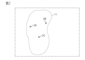
- FIG. FIG. 4 is a schematic diagram showing the relationship between a plurality of wells and aquifers on a map
- It is a schematic diagram which shows the structure of pumping equipment.
- It is a schematic diagram which shows the structure of observation equipment.
- FIG. 3 is a schematic diagram showing the relationship between the relative positional relationship of a plurality of wells and the flow direction of groundwater
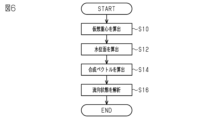
- 4 is a flowchart for explaining flow direction calculation processing executed by the server of the well monitoring system
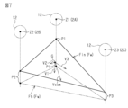
- FIG. 6 is a schematic diagram for explaining the contents of flow direction calculation processing in FIG. 5
- 4 is a flowchart for explaining drive control processing executed by the server of the well monitoring system;
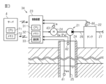
- the well monitoring system 1 includes a plurality of wells 2, a plurality of facilities 3, and a server 4. Each facility 3 is connected to a server 4 via a network 5 such as the Internet.
- a network 5 such as the Internet.
- the wells 2 include a pumping well 2A and two observation wells 2B and 2C.
- Pumping well 2A is a well for pumping groundwater from an underground area.
- the two observation wells 2B and 2C are wells for observing the groundwater level in the underground area.
- wells 2A, 2B, and 2C are installed on the same aquifer 11 in the underground area indicated by broken lines in the figure.
- Wells 2A, 2B, and 2C are installed at predetermined installation intervals.
- the distribution range of the aquifer 11 is estimated, for example, by typical techniques such as surface geological reconnaissance, geological surveys such as boring surveys, electrical surveys, water quality surveys including ion analysis, or a combination thereof. This also applies to the installation intervals of the wells 2A, 2B and 2C.
- the observation wells 2B and 2C observe the state of the groundwater level as the state of the aquifer 11 .
- the state of the groundwater level changes depending on the natural environment such as season and weather, as well as the water pumped from the pumping well 2A.
- the facility 3 includes a pumping facility 3A and two observation facilities 3B and 3C.
- the pumping well 2A is installed side by side with the pumping equipment 3A.
- the observation well 2B is installed side by side with the observation facility 3B.
- the observation well 2C is installed side by side with the observation facility 3C.
- the pumping facility 3A includes a pump 21, a tank 22, and a control device 23.
- the pump 21 pumps up groundwater from the pumping well 2A.
- the tank 22 stores groundwater pumped up by the pump 21 .
- the control device 23 controls driving of the pump 21 .
- the pump 21 is, for example, an electric pump driven by a motor 24 .
- the pump 21 may be of a type installed on land, or may be of a type placed in water.
- the pump 21 may be, for example, a pump of another drive system such as an engine drive.
- the pump 21 pumps up groundwater from the pumping well 2A through the pumping pipe 25 and delivers the pumped-up groundwater to the tank 22 through the connecting pipe 26 .
- the pumping pipe 25 extends from the pump 21 through the pumping well 2A and has a tip that is immersed in the water inside the pumping well 2A.
- the groundwater stored in the tank 22 is, for example, delivered to a facility such as a factory (not shown) through a delivery pipe 27 and appropriately treated.
- the control device 23 is a circuit made up of a PLC (Programmable Logic Controller).
- the control device 23 includes a CPU 31 , a memory 32 and a communication section 33 .
- the control device 23 executes various processes as the CPU 31 executes programs stored in the memory 32 .
- the CPU 31 and memory 32 constitute a microcomputer, which is a processing circuit.
- Memory 32 includes computer-readable media such as random access memory (RAM) and read only memory (ROM). However, it is an example that various processes are realized by software.
- the processing circuit of the control device 23 may be configured such that at least part of the processing is realized by a hardware circuit such as a logic circuit.
- the communication unit 33 is a communication circuit that exchanges signals with the server 4 via the network 5.
- the communication unit 33 transmits well information about the pumped well 2A to the server 4 at predetermined intervals of, for example, several tens of seconds to several minutes.
- the communication unit 33 receives and acquires, for example, an instruction signal instructing to drive the pump 21 , a signal instructing to stop the pump 21 , and various other instruction signals from the server 4 via the network 5 .
- the control device 23 controls driving of the pump 21 by supplying drive power to the motor 24 based on the instruction signal received via the communication unit 33 .
- the control device 23 acquires information obtained from various sensors provided in the pumping equipment 3A, and transmits the information to the server 4 via the communication unit 33 as well information regarding the pumping well 2A.
- Various sensors include a water level sensor 41, a flow rate sensor 42, a current sensor 43, and a water storage amount sensor 44.
- the water level sensor 41 detects the water level Hwa of the pumped well 2A.
- the flow rate sensor 42 detects the flow rate Qw of groundwater pumped up by the pump 21 .
- the control device 23 detects the pumping amount Pw of groundwater per unit time based on the flow rate Qw obtained through the flow rate sensor 42 . In this case, the controller 23 may take into account parameters that change with respect to the activation and/or deactivation of the pump 21, such as, for example, the duration of activation and/or deactivation of the pump 21.
- FIG. A current sensor 43 detects the current Im supplied to the motor 24 .
- the water storage amount sensor 44 detects the water storage amount Nw in the tank 22 based on the water level of the groundwater stored in the tank 22 .
- Well information includes water level information, pumping amount information, and water storage amount information.
- the water level information is the detection result of the water level Hwa of the pumping well 2A.
- the pumping amount information is the detection result of the pumping amount Pw in the pumping well 2A.
- the stored water amount information is the detection result of the stored water amount Nw. It should be noted that the location information regarding the point where the pumping well 2A is installed is stored in the memory 72 of the server 4 in advance.
- the position information includes the latitude and longitude of the point where the pumping well 2A is installed.
- the observation facility 3B includes a communication section 53B.
- the communication unit 53B is a communication circuit that exchanges signals with the server 4 via the network 5, like the communication unit 33.
- the communication unit 53B transmits well information about the observation well 2B to the server 4 at predetermined intervals of several tens of seconds to several minutes, for example.
- the communication unit 53B receives and acquires, for example, a request signal requesting well information or the like from the server 4 via the network 5 .
- the communication unit 53B acquires information obtained from various sensors provided in the observation equipment 3B, and transmits the information to the server 4 as well information regarding the observation well 2B.
- Various sensors include a water level sensor 61B.
- the water level sensor 61B detects the water level Hwb of the observation well 2B.
- Well information includes water level information.
- the water level information is the detection result of the water level Hwb of the observation well 2B.
- the location information regarding the point where the observation well 2B is installed is stored in the memory 72 of the server 4 in advance.
- the positional information includes the latitude and longitude of the point where the observation well 2B is installed. Since the observation facility 3C has the same configuration as the observation facility 3B, only the reference numerals with parentheses in FIG.
- the server 4 is, for example, a stationary server.
- the server 4 may be a cloud server that is virtually constructed on the network 5 .
- the server 4 has a CPU 71 and a memory 72 .
- the server 4 executes various processes by the CPU 71 executing a monitoring program, which is a control program stored in the memory 72 .
- the server 4 exchanges signals with the equipment 3A, 3B, 3C via the network 5.
- FIG. The server 4 receives and acquires well information about each of the wells 2A, 2B, and 2C, for example, at predetermined intervals of several tens of seconds to several minutes.
- the server 4 stores in the memory 72 the well information transmitted from the communication units 33, 53B, 53C of the facilities 3A, 3B, 3C.
- the server 4 transmits an instruction signal to the control device 23 of the pumping equipment 3A to the communication unit 33 .
- the server 4 Based on the well information stored in the memory 72, the server 4 generates and transmits an instruction signal to the control device 23 and a request signal to the communication units 53B and 53C. That is, in this embodiment, remote control by the server 4 is possible for each of the facilities 3A, 3B, and 3C.
- the CPU 71 and memory 72 of the server 4 constitute a microcomputer, which is a processing circuit.
- Various processes executed by the server 4 are functional portions realized by the CPU 71 executing the monitoring program.
- Various types of processing include flow direction analysis processing and drive control processing, for example.
- Memory 72 includes computer-readable media such as random access memory (RAM) and read only memory (ROM). However, it is an example that various processes are realized by software.
- the processing circuit of the server 4 may be configured such that at least part of the processing is realized by hardware circuits such as logic circuits.
- ⁇ Processing of server 4> For example, as shown in FIG. 5, wells 2A, 2B, and 2C are installed within a predetermined site 12 indicated by dashed lines in the drawing.
- the site 12 is adjacent to an adjacent land 13, such as another site or a river, which is demarcated by a boundary R in the figure.
- the flow direction of the groundwater which indicates the direction in which the groundwater flows in the site 12, changes in various directions other than the directions indicated by the arrows in the figure.
- the server 4 includes flow direction analysis processing and drive control processing for analyzing the flow direction state of the groundwater and controlling the flow direction of the groundwater. Executes various processing.
- the flow direction analysis processing shown in FIG. 6 is processing for analyzing the flow direction state of the groundwater within the site 12 .
- the server 4 executes the flow direction analysis process in the following order at each predetermined cycle.
- the server 4 calculates the virtual center of gravity of the groundwater level plane estimated from the water levels of the wells 2A, 2B, and 2C based on the position information and the water level information of the wells 2A, 2B, and 2C. G is calculated (step S10). At step S10, the server 4 calculates the virtual center of gravity G based on the distances between the points of the wells 2A, 2B, 2C and the respective water levels Hwa, Hwb, Hwc.
- the server 4 calculates three virtual points P1, P2, and P3 as points on virtually defined three-dimensional coordinates.
- a virtual point P1 corresponds to the pumped well 2A.
- the virtual point P1 is obtained by considering the water level Hwa with respect to the coordinate Z1 corresponding to the point on the map of the pumped well 2A.
- Virtual point P2 corresponds to observation well 2B.
- the virtual point P2 is obtained by considering the water level Hwb for the coordinate Z2 corresponding to the point on the map of the observation well 2B.
- Virtual point P3 corresponds to observation well 2C.
- the virtual point P3 is obtained by considering the water level Hwc with respect to the coordinate Z3 corresponding to the point on the map of the observation well 2C.
- the virtual points P1, P2, and P3 are arranged in the vertical direction in the figure while the coordinates corresponding to the points on the map do not change when the water levels Hwa, Hwb, and Hwc of the corresponding wells 2A, 2B, and 2C change. changes in the vertical direction.
- the server 4 then calculates a virtual center of gravity G, which is the center of gravity of the virtual points P1, P2, and P3.
- the server 4 calculates a water level plane Fw, which is a virtual plane obtained by connecting the virtual points P1, P2, and P3 calculated in step S10 (step S12).
- the server 4 calculates a triangular portion surrounded by lines connecting the virtual points P1, P2, and P3 as the water level plane Fw among the planes including all the virtual points P1, P2, and P3.
- the server 4 calculates the water level plane Fw, which is the horizontal plane Fh indicated by the two-dot chain line in the figure. Further, when the water levels Hwa, Hwb, and Hwc are different from each other, the server 4 calculates the water level plane Fw which becomes the inclined plane Fin indicated by the solid line in the figure.
- the virtual points P1, P2, and P3 change as the water level changes, the direction in which the water level surface Fw inclines and the surface area of the water level surface Fw can change.
- the server 4 calculates a combined vector Vcom indicating the direction and magnitude of the gradient of the water level surface Fw based on the virtual center of gravity G and the water level surface Fw calculated in steps S10 and S12 (step S14 ).
- the server 4 calculates three vectors V1, V2, V3 indicating the direction and magnitude of the gradient of the water level surface Fw between the virtual center of gravity G and each of the three virtual points P1, P2, P3.
- the composite vector Vcom is calculated.
- the server 4 calculates three vectors V1, V2, and V3 indicated by dashed lines in the figure at the virtual center of gravity G of the inclined plane Fin.
- the directions of the vectors V1, V2, V3 indicate the direction of the gradient of the water level surface Fw
- the magnitudes of the vectors V1, V2, V3 indicate the magnitude of the gradient of the water level surface Fw, that is, the strength.
- a vector V1 indicates the direction and magnitude of the gradient of the water level surface Fw between the virtual center of gravity G and the virtual point P1.
- a vector V2 indicates the direction and magnitude of the gradient of the water level surface Fw between the virtual center of gravity G and the virtual point P2.
- a vector V3 indicates the direction and magnitude of the gradient of the water level surface Fw between the virtual center of gravity G and the virtual point P3.
- the server 4 calculates a combined vector Vcom indicated by a solid line in the drawing, which is obtained by combining the vectors V1, V2, and V3.
- the resultant vector Vcom thus obtained indicates the direction and magnitude of the gradient of the inclined plane Fin. That is, the composite vector Vcom indicates the water level gradient of the water level surface Fw.
- step S16 the server 4 analyzes the groundwater flow direction based on the direction and magnitude of the combined vector Vcom.
- the server 4 calculates the composite vector Vcom extending from the virtual center of gravity G in the direction away from the virtual point P1
- the groundwater flows in the direction indicated by the arrow in FIG. Analyze that it is a flow direction state. This indicates that the groundwater in the site 12 may flow out to the adjacent land 13 beyond the boundary R.
- the magnitude of the combined vector Vcom indicates the strength of groundwater flow, that is, the flow velocity.
- the drive control process shown in FIG. 8 is a process for driving and controlling the pump 21 to adjust the pumping amount Pw in the pumping well 2A. It should be noted that the server 4 executes the drive control process in the following order at each predetermined cycle.
- the server 4 calculates the target water level Hwt of the water level Hwa of the pumping well 2A based on the flow direction state of the groundwater obtained as a result of the flow direction analysis process shown in FIG. 6 (step S20). In step S20, the server 4 calculates the target water level Hwt for changing the current water level surface Fw in order to change the current flow direction state.
- the server 4 changes the combined vector Vcom to a zero vector when calculating the target water level Hwt so that the inclined plane Fin is parallel to the horizontal plane Fh.
- the server 4 calculates the target water level Hwt such that the inclined plane Fin is inclined downward toward the virtual point P1
- the server 4 changes the combined vector Vcom so as to extend from the virtual center of gravity G toward the virtual point P1. That is, the server 4 changes the current flow direction state to a groundwater flow direction state in which the groundwater does not flow from the site 12 over the boundary R to the adjacent land 13 .
- the server 4 has, for example, a map that defines the relationship between the target water level Hwt and the characteristic value obtained by parameterizing the water level Hwa and the flow direction of the groundwater.
- the server 4 uses the water level Hwa and the characteristic value as inputs to map-calculate the target water level Hwt.
- the map may further include water levels Hwb and Hwc as inputs.
- a plurality of maps may be prepared so that a map can be selected according to the natural environment such as season or weather.
- the server 4 calculates the pumping amount Pw required to bring the water level Hwa of the pumping well 2A to the target water level Hwt calculated in step S20 (step S22). ).
- the server 4 drives and controls the pump 21 so as to adjust the pumping amount Pw of the pumping well 2A to the pumping amount Pw calculated in step S22 (step S24).
- the server 4 instructs the pump 21 to drive, stop, etc. so as to increase or decrease the pumping amount Pw according to the magnitude of the deviation of the current water level Hwa from the target water level Hwt.
- the server 4 transmits an instruction signal to the control device 23 to the communication section 33 .
- the server 4 can analyze the current flow direction of groundwater in the underground regions around the wells 2A, 2B, and 2C by executing the flow direction analysis process.
- the server 4 when there is a possibility that the groundwater in the site 12 flows over the boundary R to the adjacent land 13, the server 4 changes the current flow direction of the groundwater to change the direction in which the groundwater flows. determine that it is necessary to control
- the server 4 adjusts the pumping amount Pw in the pumping well 2A by executing drive control processing.
- the server 4 can adjust the pumping amount Pw so as to change the current flow direction of the groundwater to a state where the groundwater does not flow out from the site 12 to the adjacent land 13 beyond the boundary R. That is, the server 4 can appropriately adjust the pumping amount Pw in the pumping well 2A in order to control the direction of groundwater flow.
- the server 4 can adjust the pumping amount Pw while monitoring the current flow direction of the groundwater in order to control the direction in which the groundwater flows. That is, in the pumping well 2A, the amount of groundwater to be pumped can be optimized. In this case, it is possible to ease restrictions on the facility capacity used to treat the pumped groundwater. Therefore, it is possible to reduce the burden of treating the pumped groundwater.
- the server 4 analyzes the groundwater flow direction based on the water level information obtained from the water level sensors 41, 61B, 61C of the wells 2A, 2B, 2C.
- the water level sensors 41, 61B, 61C are components necessary for periodic inspection or maintenance of the wells 2A, 2B, 2C. Therefore, the configuration required for controlling the direction of groundwater flow can be shared with the configuration used for other purposes. As a result, the scale of modification required to realize control of the direction of groundwater flow can be reduced for the configuration of the well monitoring system 1 .
- the server 4 calculates the combined vector Vcom as the water level gradient for analysis of the groundwater flow direction.
- Such a composite vector Vcom can quantitatively represent the direction in which groundwater flows. This is effective in facilitating the analysis of groundwater flow direction.
- the server 4 uses the virtual center of gravity G to calculate the combined vector Vcom. In this case, there is no need to consider differences in distances between the virtual center of gravity G and the three virtual points P1, P2, and P3. This is effective in simplifying computation.
- the server 4 can change the current flow direction of groundwater to a desired state by adjusting the amount of pumped water Pw in the pumping well 2A to increase or decrease. On the other hand, if the current flow direction of the groundwater can be maintained because the current flow direction of the groundwater is the desired state, the server 4 adjusts the pumping well 2A so as to decrease the pumping amount Pw or operates the pump 21. can be stopped. As a result, pumping for controlling the direction of groundwater flow can be minimized in the pumping well 2A.
- the server 4 changes the current flow direction of the groundwater so that it becomes more difficult for groundwater to flow from the site 12 across the boundary R to the adjacent land 13 than in the current flow direction, as a desired state. It is sufficient if the state can be changed.
- the server 4 may adjust the pumping amount Pw of the pumping well 2A by considering the pumping amount information and/or the state of the pumping equipment 3A such as the water storage amount Nw in the tank 22 to increase or decrease the pumping amount Pw. This is effective in optimizing the amount of groundwater pumped in pumping well 2A.
- the server 4 may receive and acquire the position information of each of the wells 2A, 2B, and 2C from the outside.
- Each facility 3A, 3B, 3C may transmit the location information to the server 4.
- each facility 3A, 3B, 3C may be provided with a GPS sensor or the like.
- the server 4 may or may not store the position information of each well 2A, 2B, 2C in the memory 72 in advance.
- step S10 for calculating the virtual center of gravity G may be deleted.
- the server 4 fixes the coordinates corresponding to a predetermined point in the site 12 on the map, and calculates the intersection of the building line and the water level surface Fw in the vertical direction including the coordinates. may be calculated.
- the server 4 may calculate a plurality of points as points to be calculated instead of the virtual center of gravity G.
- FIG. the combined vectors obtained for each point may be further combined to calculate the final combined vector.
- the method of calculating the water level surface Fw can be changed as appropriate.
- the server 4 may calculate the horizontal plane according to the water level of the coordinate having the lowest water level among the coordinates Z1, Z2 and Z3. Subsequently, the server 4 may calculate the water level plane Fw by tilting the horizontal plane according to the water levels of the remaining coordinates.
- step S20 for calculating the target water level Hwt may be deleted.
- the server 4 may monitor the state of flow direction of groundwater obtained as a result of the flow direction analysis process and adjust the pumping amount Pw so that the state of flow direction becomes a desired state. In this case, in the pumping well 2A, excessive pumping can be suppressed as compared with the case where the pumping amount Pw is not adjusted.
- the server 4 may only transmit information on the required pumping amount Pw when adjusting the pumping amount Pw.
- specific control such as driving and stopping of the pump may be executed mainly by the control device 23 .
- the server 4 may be one that executes at least flow direction analysis processing.
- the drive control process may be configured as a process executed by the control device 23 .
- the control device 23 does not have to transmit the pumping amount information to the server 4 .
- the configuration of the pumping facility 3A can be changed as appropriate, for example, by removing the tank 22 .
- the flow rate sensor 42 can be deleted.
- the control device 23 can estimate the pumping amount Pw from the drive time and/or drive frequency of the pump 21 .
- wells 2A, 2B, and 2C to be monitored by the well monitoring system 1 do not have to be installed on the same aquifer 11 .
- wells 2A, 2B, 2C may include wells located on different aquifers.
- the well monitoring system 1 may monitor three or more wells as observation wells. For example, when three observation wells are to be monitored, the server 4 extracts two of the three observation wells, and uses the combination of the two extracted observation wells and the pumping well 2A as information for flow direction analysis processing and the like. Can be used as a source. In this case, three sets of pumping wells and two observation wells can be extracted. For example, the server 4 may calculate a composite vector for each of the three pairs, and further combine the composite vectors obtained from the three pairs to obtain a final composite vector Vcom.
- the well monitoring system 1 may monitor two or more wells as pumping wells.
- the server 4 uses a combination of the two pumping wells and one observation well extracted from the two observation wells as an information source for flow direction analysis processing and the like. You may In this case, either one or both of the two pumping wells may be subject to drive control through the drive control process.
- the well monitoring system 1 may monitor three or more observation wells that do not include pumping wells.
- the server 4 uses the three observation wells as information sources for flow direction analysis processing and the like.
- the well monitoring system 1 only needs to include at least the server 4 .
- the well 2 or facility 3 to be monitored may be omitted from the configuration of the well monitoring system 1 .
Landscapes
- Life Sciences & Earth Sciences (AREA)
- Engineering & Computer Science (AREA)
- Chemical & Material Sciences (AREA)
- Physics & Mathematics (AREA)
- Analytical Chemistry (AREA)
- Soil Sciences (AREA)
- General Physics & Mathematics (AREA)
- General Life Sciences & Earth Sciences (AREA)
- Mining & Mineral Resources (AREA)
- Paleontology (AREA)
- Civil Engineering (AREA)
- General Engineering & Computer Science (AREA)
- Structural Engineering (AREA)
- Investigation Of Foundation Soil And Reinforcement Of Foundation Soil By Compacting Or Drainage (AREA)
- Sewage (AREA)
Abstract
Description
図1に示すように、井戸監視システム1は、複数の井戸2と、複数の設備3と、サーバ4とを備えている。設備3の各々は、インターネット等のネットワーク5を介してサーバ4に接続されている。なお、説明の便宜上、井戸監視システム1の監視対象となる井戸が3つの場合を例示している。
図1に示すように、井戸2は、揚水井戸2Aと、2つの観測井戸2B,2Cとを含む。揚水井戸2Aは、地下領域から地下水を揚水するための井戸である。2つの観測井戸2B,2Cは、地下領域の地下水の水位を観測するための井戸である。
設備3は、揚水設備3Aと、2つの観測設備3B,3Cとを含む。揚水井戸2Aは、揚水設備3Aに並設されている。観測井戸2Bは、観測設備3Bに並設されている。観測井戸2Cは、観測設備3Cに並設されている。
図1、図3、及び図4に示すように、サーバ4は、たとえば、設置型のサーバである。なお、サーバ4は、ネットワーク5上に仮想的に構築されたクラウドサーバであってもよい。サーバ4は、CPU71と、メモリ72とを備えている。サーバ4は、メモリ72に記憶された制御プログラムである監視プログラムをCPU71が実行することにより、各種処理を実行する。サーバ4は、ネットワーク5を介して各設備3A,3B,3Cとの間で信号を授受する。サーバ4は、各井戸2A,2B,2Cに関する井戸情報を、たとえば、数十秒から数分程度の所定間隔で受信して取得する。
たとえば、図5に示すように、井戸2A,2B,2Cは、図中に破線で示す所定の敷地12内に設置されている。敷地12は、別の敷地や河川等、図中の境界Rで区画された隣接地13に隣接している。この場合、敷地12内の地下水が流れる方向を示す地下水の流向状態は、図中に矢印で示す方向の他、様々な方向に変化する。たとえば、地下水の流向状態は、図中の矢印で示す方向を向いている場合、敷地12内の地下水が隣接地13へと流れ出る可能性があることを示す。そこで、敷地12内の地下水が隣接地13へと流れ出ることを抑えるべく、サーバ4は、地下水の流向状態を解析して地下水の流れる方向をコントロールするための流向解析処理と駆動制御処理とを含む各種処理を実行する。
図6に示す流向解析処理は、敷地12内の地下水の流向状態を解析するための処理である。サーバ4は、定められた周期毎に、以下の順で流向解析処理を実行する。
図8に示す駆動制御処理は、揚水井戸2Aにおける揚水量Pwを調整するべくポンプ21を駆動及び制御するための処理である。なお、サーバ4は、定められた周期毎に、以下の順で駆動制御処理を実行する。
上記構成によれば、サーバ4は、流向解析処理を実行することによって、井戸2A,2B,2Cの周辺の地下領域の地下水の現在の流向状態を解析することができる。
(1)サーバ4は、地下水が流れる方向をコントロールするために、地下水の現在の流向状態をモニタしながら揚水量Pwを調整することができる。つまり、揚水井戸2Aでは、揚水される地下水の量を最適化できる。この場合、揚水された地下水の処理に用いる設備能力の制限を緩和することができる。したがって、揚水された地下水の処理に係る負担を低減することができる。
上記実施形態は次のように変更してもよい。また、以下の他の実施形態は、技術的に矛盾しない範囲において、互いに組み合わせることができる。
・流向解析処理では、仮想重心Gを算出するステップS10の処理を削除してもよい。たとえば、サーバ4は、仮想重心Gを算出する代わりに、地図上の敷地12内の所定の地点に対応する座標を固定とし、当該座標を含む鉛直方向に延ビル線と水位面Fwとの交点を算出するようにしてもよい。また、サーバ4は、仮想重心Gの代わりに算出する点として複数の点を算出してもよい。この場合、それぞれの点について得られる合成ベクトル同士をさらに合成して最終的な合成ベクトルを算出してもよい。
・駆動制御処理では、目標水位Hwtを算出するステップS20の処理を削除してもよい。たとえば、サーバ4は、流向解析処理の結果として得られる地下水の流向状態をモニタしながら当該流向状態が所望の状態となるように揚水量Pwを調整すればよい。この場合、揚水井戸2Aでは、揚水量Pwを調整しない場合と比べて余分な揚水を抑えることができる。
Claims (8)
- 3つ以上である複数の井戸を監視する井戸監視システムであって、
前記複数の井戸が設置されているそれぞれの地点に関する位置情報を記憶又は取得するとともに、前記複数の井戸のそれぞれの水位に関する水位情報を取得するように構成されたサーバを含み、
前記サーバは、
前記複数の井戸のそれぞれの設備から、前記井戸の水位に関する前記水位情報を取得し、
前記複数の井戸についての前記位置情報と前記水位情報とに基づいて、前記複数の井戸の周辺の地下領域における地下水が流れる方向を示す流向状態を解析する流向解析処理を含む、ように構成されている井戸監視システム。 - 前記複数の井戸は、少なくとも1つの揚水井戸と、少なくとも1つの観測井戸とを含み、
前記流向解析処理は、
前記位置情報が示す前記複数の井戸の前記地点と、前記水位情報が示す前記複数の井戸の前記水位とから、地下水の水位の勾配である水位勾配を算出する処理と、
前記水位勾配に基づき前記流向状態を解析する処理と、を含む、請求項1に記載の井戸監視システム。 - 前記複数の井戸は、1つの前記揚水井戸と、2つの前記観測井戸とを含み、
前記水位勾配を算出する処理は、
前記1つの前記揚水井戸及び前記2つの前記観測井戸のそれぞれの前記地点と、前記1つの前記揚水井戸及び前記2つの前記観測井戸のそれぞれの前記水位とによって仮想的に規定される3つの仮想点を算出する処理と、
前記3つの仮想点を結んで得られる仮想的な平面の勾配を前記水位勾配として算出する処理と、を含む、請求項2に記載の井戸監視システム。 - 前記水位勾配を算出する処理は、
前記3つの仮想点の仮想重心を算出する処理と、
前記仮想重心と前記3つの仮想点それぞれとの間における前記仮想的な平面の勾配の向きと大きさとを示す3つのベクトルを算出する処理と、
前記3つのベクトルを合成して得られる合成ベクトルを前記水位勾配として算出する処理と、を含む、請求項3に記載の井戸監視システム。 - 前記複数の井戸は、少なくとも1つの揚水井戸を含み、
前記サーバは、
前記揚水井戸から地下水を汲み上げる揚水設備が前記揚水井戸から汲み上げた地下水の量である揚水量に関する揚水量情報を、前記揚水設備から取得し、
前記流向解析処理の結果として得られる前記流向状態と取得した前記揚水量情報とに基づいて、前記揚水量を調整するべく前記揚水設備を制御する駆動制御処理を含む、請求項1~請求項4のうちいずれか一項に記載の井戸監視システム。 - 前記駆動制御処理は、
前記流向解析処理の結果として得られる前記流向状態を変化させるべく、前記揚水井戸の前記水位の目標水位を算出する処理と、
前記揚水井戸の前記水位が前記目標水位となるように、前記揚水量情報に基づき前記揚水量を調整する処理と、を含む、請求項5に記載の井戸監視システム。 - 前記複数の井戸は、少なくとも1つの揚水井戸と、少なくとも1つの観測井戸とを含み、
前記揚水井戸から地下水を汲み上げる揚水設備は、
前記揚水井戸から地下水を汲み上げるように構成されたポンプと、
前記揚水井戸の水位を検出するように構成された水位センサと、
前記水位センサの検出結果を前記水位情報として前記サーバに送信するように構成された通信部と、を有し、
前記観測井戸の水位を検出する観測設備は、
前記観測井戸の水位を検出するように構成された水位センサと、
前記水位センサの検出結果を前記水位情報として前記サーバに送信するように構成された通信部とを有する、請求項1~請求項6のうちいずれか一項に記載の井戸監視システム。 - 請求項1~請求項7のうちいずれか一項に記載の井戸監視システムの前記サーバが有するコンピュータが実行する監視プログラムであって、
前記コンピュータに、前記流向解析処理を実行させるように構成されている監視プログラム。
Priority Applications (2)
| Application Number | Priority Date | Filing Date | Title |
|---|---|---|---|
| JP2023567353A JP7729399B2 (ja) | 2021-12-14 | 2021-12-14 | 井戸監視システム及び監視プログラム |
| PCT/JP2021/046115 WO2023112166A1 (ja) | 2021-12-14 | 2021-12-14 | 井戸監視システム及び監視プログラム |
Applications Claiming Priority (1)
| Application Number | Priority Date | Filing Date | Title |
|---|---|---|---|
| PCT/JP2021/046115 WO2023112166A1 (ja) | 2021-12-14 | 2021-12-14 | 井戸監視システム及び監視プログラム |
Publications (1)
| Publication Number | Publication Date |
|---|---|
| WO2023112166A1 true WO2023112166A1 (ja) | 2023-06-22 |
Family
ID=86773742
Family Applications (1)
| Application Number | Title | Priority Date | Filing Date |
|---|---|---|---|
| PCT/JP2021/046115 Ceased WO2023112166A1 (ja) | 2021-12-14 | 2021-12-14 | 井戸監視システム及び監視プログラム |
Country Status (2)
| Country | Link |
|---|---|
| JP (1) | JP7729399B2 (ja) |
| WO (1) | WO2023112166A1 (ja) |
Citations (6)
| Publication number | Priority date | Publication date | Assignee | Title |
|---|---|---|---|---|
| JP2005091295A (ja) * | 2003-09-19 | 2005-04-07 | Makoto Nishigaki | 地下水位調査方法 |
| JP2006221402A (ja) * | 2005-02-10 | 2006-08-24 | Shimizu Corp | 地下水開発施設における地下水管理システム |
| JP2007263957A (ja) * | 2006-03-01 | 2007-10-11 | Nippon Steel Engineering Co Ltd | 地下水流れ状態推定装置及び方法、土壌の有効熱伝導率推定方法、並びに地盤調査方法 |
| JP2008062206A (ja) * | 2006-09-08 | 2008-03-21 | Murao Giken:Kk | 地下水制御管理システム |
| US20110100642A1 (en) * | 2009-10-29 | 2011-05-05 | Fabien Cens | Instrumented tubing and method for determining a contribution to fluid production |
| CN111704180A (zh) * | 2020-06-18 | 2020-09-25 | 湖南恒凯环保科技投资有限公司 | 一种强化地下水污染修复的原位注入装置及工艺 |
-
2021
- 2021-12-14 JP JP2023567353A patent/JP7729399B2/ja active Active
- 2021-12-14 WO PCT/JP2021/046115 patent/WO2023112166A1/ja not_active Ceased
Patent Citations (6)
| Publication number | Priority date | Publication date | Assignee | Title |
|---|---|---|---|---|
| JP2005091295A (ja) * | 2003-09-19 | 2005-04-07 | Makoto Nishigaki | 地下水位調査方法 |
| JP2006221402A (ja) * | 2005-02-10 | 2006-08-24 | Shimizu Corp | 地下水開発施設における地下水管理システム |
| JP2007263957A (ja) * | 2006-03-01 | 2007-10-11 | Nippon Steel Engineering Co Ltd | 地下水流れ状態推定装置及び方法、土壌の有効熱伝導率推定方法、並びに地盤調査方法 |
| JP2008062206A (ja) * | 2006-09-08 | 2008-03-21 | Murao Giken:Kk | 地下水制御管理システム |
| US20110100642A1 (en) * | 2009-10-29 | 2011-05-05 | Fabien Cens | Instrumented tubing and method for determining a contribution to fluid production |
| CN111704180A (zh) * | 2020-06-18 | 2020-09-25 | 湖南恒凯环保科技投资有限公司 | 一种强化地下水污染修复的原位注入装置及工艺 |
Also Published As
| Publication number | Publication date |
|---|---|
| JPWO2023112166A1 (ja) | 2023-06-22 |
| JP7729399B2 (ja) | 2025-08-26 |
Similar Documents
| Publication | Publication Date | Title |
|---|---|---|
| Meyer et al. | A method for locating wells in a groundwater monitoring network under conditions of uncertainty | |
| CN111699379B (zh) | 用于管道的智能数据采集系统和方法 | |
| CN1062643C (zh) | 控制雨水泵运行的设备和方法 | |
| US9382798B2 (en) | Method and system for fluid flow control in a fluid network system | |
| CN110188493B (zh) | 船舶减摇控制方法、装置及系统 | |
| CN110032555A (zh) | 一种神经网络塔吊风险预测方法及系统 | |
| CN120255315A (zh) | 一种多模态感知与强化学习的工程机械智能调控方法及系统 | |
| WO2023112166A1 (ja) | 井戸監視システム及び監視プログラム | |
| CN120068619A (zh) | 基于深度学习的靶向定位注浆高效封堵加固方法及系统 | |
| CN113932877B (zh) | 一种矿区的岩溶水位预测方法及终端设备 | |
| WO2021126844A1 (en) | Earthmoving flow vector generation using node and connection input graph | |
| CA3074504A1 (en) | Systems, devices, and methods for vehicle speed control | |
| CN120429919A (zh) | 一种基坑降水的处理方法、系统、电子设备及存储介质 | |
| CN114218629A (zh) | 一种城市地下管廊系统及大数据分析方法 | |
| KR20150071911A (ko) | 투묘지 이탈 선박 제어 장치 및 그 방법 | |
| CN105359047A (zh) | 用于流体网络系统中的流体流量控制的方法和系统 | |
| JP7422573B2 (ja) | 災害発生時における水処理施設の運転管理方法及び運転管理システム | |
| JP6749254B2 (ja) | 下水道設備の監視制御装置及び下水ポンプ場の運転制御方法 | |
| CN119098477B (zh) | 土壤污染的修复控制方法、系统、介质和计算机程序产品 | |
| Ly et al. | A fully autonomous robot for putting posts for trellising vineyard with centimetric accuracy | |
| JP2020142161A (ja) | 水処理システム、水処理方法、運転支援装置及びプログラム | |
| JP2002258943A (ja) | 洋上遠隔監視システム | |
| CN118551901B (zh) | 一种地下水污染防控方法和系统 | |
| CN109991637B (zh) | 定位方法、定位装置和计算机可读存储介质 | |
| Jones | Adaptive control of ground-water hydraulics |
Legal Events
| Date | Code | Title | Description |
|---|---|---|---|
| 121 | Ep: the epo has been informed by wipo that ep was designated in this application |
Ref document number: 21968083 Country of ref document: EP Kind code of ref document: A1 |
|
| WWE | Wipo information: entry into national phase |
Ref document number: 2023567353 Country of ref document: JP |
|
| WWE | Wipo information: entry into national phase |
Ref document number: 202417050918 Country of ref document: IN |
|
| NENP | Non-entry into the national phase |
Ref country code: DE |
|
| 122 | Ep: pct application non-entry in european phase |
Ref document number: 21968083 Country of ref document: EP Kind code of ref document: A1 |