WO2023112077A1 - Ventilateur axial, soufflante et dispositif à cycle frigorifique - Google Patents
Ventilateur axial, soufflante et dispositif à cycle frigorifique Download PDFInfo
- Publication number
- WO2023112077A1 WO2023112077A1 PCT/JP2021/045745 JP2021045745W WO2023112077A1 WO 2023112077 A1 WO2023112077 A1 WO 2023112077A1 JP 2021045745 W JP2021045745 W JP 2021045745W WO 2023112077 A1 WO2023112077 A1 WO 2023112077A1
- Authority
- WO
- WIPO (PCT)
- Prior art keywords
- axial fan
- region
- stress
- stress dispersion
- fan
- Prior art date
Links
- 238000005057 refrigeration Methods 0.000 title claims description 11
- 239000006185 dispersion Substances 0.000 claims description 83
- 230000002093 peripheral effect Effects 0.000 claims description 54
- 238000007664 blowing Methods 0.000 claims description 21
- 239000003507 refrigerant Substances 0.000 claims description 11
- 230000007423 decrease Effects 0.000 claims description 8
- 230000001419 dependent effect Effects 0.000 claims 1
- 230000000052 comparative effect Effects 0.000 description 24
- 238000010586 diagram Methods 0.000 description 20
- 230000000694 effects Effects 0.000 description 16
- 230000008859 change Effects 0.000 description 7
- 230000004048 modification Effects 0.000 description 7
- 238000012986 modification Methods 0.000 description 7
- 230000015572 biosynthetic process Effects 0.000 description 6
- 238000011144 upstream manufacturing Methods 0.000 description 6
- 239000013585 weight reducing agent Substances 0.000 description 6
- 230000008901 benefit Effects 0.000 description 5
- 238000013461 design Methods 0.000 description 5
- 238000012546 transfer Methods 0.000 description 5
- 230000006872 improvement Effects 0.000 description 4
- 238000012423 maintenance Methods 0.000 description 4
- 238000001816 cooling Methods 0.000 description 3
- 238000010438 heat treatment Methods 0.000 description 3
- 238000005192 partition Methods 0.000 description 3
- 238000002347 injection Methods 0.000 description 2
- 239000007924 injection Substances 0.000 description 2
- 238000001746 injection moulding Methods 0.000 description 2
- 239000011347 resin Substances 0.000 description 2
- 229920005989 resin Polymers 0.000 description 2
- XLYOFNOQVPJJNP-UHFFFAOYSA-N water Substances O XLYOFNOQVPJJNP-UHFFFAOYSA-N 0.000 description 2
- 239000012141 concentrate Substances 0.000 description 1
- 238000000034 method Methods 0.000 description 1
- 230000000149 penetrating effect Effects 0.000 description 1
- 230000009467 reduction Effects 0.000 description 1
- 230000003014 reinforcing effect Effects 0.000 description 1
- 238000009423 ventilation Methods 0.000 description 1
Images


Classifications
-
- F—MECHANICAL ENGINEERING; LIGHTING; HEATING; WEAPONS; BLASTING
- F04—POSITIVE - DISPLACEMENT MACHINES FOR LIQUIDS; PUMPS FOR LIQUIDS OR ELASTIC FLUIDS
- F04D—NON-POSITIVE-DISPLACEMENT PUMPS
- F04D29/00—Details, component parts, or accessories
- F04D29/26—Rotors specially for elastic fluids
- F04D29/32—Rotors specially for elastic fluids for axial flow pumps
- F04D29/38—Blades
Definitions
- the present disclosure relates to an axial fan provided with blades, a blower provided with the axial fan, and a refrigeration cycle device.
- a conventional axial fan includes a plurality of blades and a boss portion to which the blades are connected, and rotates the blades to generate an air flow (see, for example, Patent Document 1 reference).
- the axial fan described in Patent Document 1 reduces backflow of air on the inner peripheral side of the axial fan and reduces blowing noise.
- the auxiliary blade is formed to extend rearward in the rotational direction from the trailing edge of the blade.
- the axial flow fan described in Patent Document 1 is provided with a cylindrical boss at its center.
- a bossless type axial flow fan hereinafter referred to as a bossless fan
- no boss portion is provided.
- connection portion In the bossless fan, the trailing edge of the blade positioned forward in the rotational direction and the leading edge of the blade positioned rearward in the rotational direction, among the adjacent blades, are continuous surfaces without the boss intervening. (hereinafter referred to as a connection portion).
- the bossless fan has no boss in the center, so the above problem is alleviated.
- the bossless fan is not provided with a boss, the strength of the central portion is reduced.
- the amount of deformation of the blade due to the centrifugal force generated during rotation increases, and the shape of the blade cannot be maintained, resulting in a problem of reduced air blowing function.
- the blades rotate at high speed, and there is a possibility that the blades or the connection part may break due to centrifugal force.
- the present disclosure has been made in order to solve such problems, and it is possible to achieve both the merits of bossless design (that is, the weight reduction of the axial fan and the improvement of the air blowing efficiency) and the maintenance of the blade strength. , an axial fan, a blower, and a refrigeration cycle device.
- An axial flow fan includes a plurality of blades that rotate about a fan shaft, and a plate-shaped blade that is formed around the fan shaft and connects circumferentially adjacent blades among the plurality of blades. a connecting portion, the connecting portion having a discontinuous portion, the discontinuous portion constituting a stress dispersing portion that distributes stress applied to the connecting portion when the plurality of blades rotate. It is.
- a blower according to the present disclosure includes the axial fan, a driving source that applies driving force to the axial fan, and a casing that houses the axial fan and the driving source.
- a refrigeration cycle apparatus includes the blower and a refrigerant circuit having a condenser and an evaporator, and the blower blows air to at least one of the condenser and the evaporator.
- the stress dispersing portion is provided at the connecting portion that connects the blades adjacent to each other in the circumferential direction. Also, the stress dispersing portion is composed of a discontinuous portion of the connecting portion. The weight of the connecting portion is reduced by the amount of the discontinuous portion provided in the connecting portion. As described above, according to the axial flow fan according to the present disclosure, the weight of the connecting portion can be reduced because the stress dispersion portion is composed of discontinuous portions. As a result, it is possible to maintain the strength of the blade while maintaining the merits of bossless design (that is, reducing the weight of the axial fan and improving the blowing efficiency).
- FIG. 1 is a front view showing the configuration of axial fan 10 according to Embodiment 1.
- FIG. 1 is a perspective view showing the configuration of axial fan 10 according to Embodiment 1.
- FIG. 2 is a side view showing the configuration of axial fan 10 according to Embodiment 1.
- FIG. FIG. 4 is a front view showing the configuration of an axial fan 10R according to a comparative example;
- FIG. 5 is a partially enlarged view of FIG. 4;
- FIG. 11 is an explanatory diagram showing a change in the radial direction of an interval Lint between ridge lines, which will be described later, in an axial fan 10R according to a comparative example;
- FIG. 1 is a front view showing the configuration of axial fan 10 according to Embodiment 1.
- FIG. 1 is a perspective view showing the configuration of axial fan 10 according to Embodiment 1.
- FIG. 2 is a side view showing the configuration of axial fan 10 according to Embodiment 1.
- FIG. FIG. 4
- FIG. 4 is a diagram for explaining stress concentration in an axial fan 10R according to a comparative example; 4 is a front view showing the structure of a stress dispersing section 8 provided in the axial fan 10 according to Embodiment 1.
- FIG. FIG. 4 is an explanatory diagram showing a change in the radial direction of the interval Lint between the ridgelines in the stress dispersion portion 8 in the axial fan 10 according to Embodiment 1;
- FIG. 3 is a partial front view showing a configuration of a modification of axial fan 10 according to Embodiment 1; 4A and 4B are diagrams for explaining a stress dispersion effect in the axial fan 10 according to the first embodiment;
- FIG. 4 is a partially enlarged side view for explaining airflow at the connecting portion 7 of the axial fan 10 according to Embodiment 1.
- FIG. 4 is a partially enlarged side view for explaining airflow at the connecting portion 7 of the axial fan 10 according to Embodiment 1.
- FIG. 4 is an explanatory diagram for explaining the shape of the blade 1 of the axial fan 10 according to the first embodiment;
- FIG. 4 is an explanatory diagram for explaining the shape of the blade 1 of the axial fan 10 according to the first embodiment;
- FIG. 8 is a partial front view showing the configuration of axial fan 10 according to Embodiment 2;
- FIG. 5 is a reference diagram showing an example of how stress is dispersed in the stress dispersion portion 8 of the axial fan 10 according to the first embodiment.
- FIG. 11 is a partial front view showing the configuration of an axial fan 10 according to Embodiment 3;
- FIG. 11 is a partial front view showing a configuration of a modification of axial fan 10 according to Embodiment 3;
- FIG. 11 is a schematic diagram of an air conditioner that is a refrigeration cycle device according to Embodiment 4;
- FIG. 11 is a perspective view of an outdoor unit as an example of a blower according to Embodiment 4, viewed from the outlet side;
- FIG. 23 is a diagram for explaining the configuration of the outdoor unit shown in FIG. 22 from the top side;
- FIG. 11 is a perspective view showing the configuration of an outdoor unit as an example of a fan according to Embodiment 5;
- FIG. 25 is a partial cross-sectional view for explaining the configuration of the outdoor unit shown in FIG. 24;
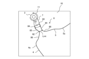
- FIG. 1 is a front view showing the structure of an axial fan 10 according to Embodiment 1.
- FIG. 2 is a perspective view showing the configuration of axial fan 10 according to the first embodiment.
- FIG. 3 is a side view showing the configuration of axial fan 10 according to the first embodiment.
- the axial fan 10 according to the first embodiment is a bossless axial fan having no boss.
- the axial fan 10 has a plurality of blades 1 and rotates about the fan shaft 2 as a central axis. Although three blades 1 are provided in the example of FIG. 1, the number of blades 1 is not limited to this.
- the fan shaft 2 is the central shaft of the axial fan 10 and extends in the axial direction S shown in FIG.
- a cylindrical shaft support portion 3 for supporting a drive shaft 62 (see FIG. 23) of a fan motor 61 (see FIG. 23) is arranged.
- a through hole 3a is formed in the central portion of the shaft support portion 3.
- a drive shaft 62 (see FIG. 23) of a fan motor 61 is engaged with the through hole 3a.
- a central axis of the drive shaft 62 is the fan shaft 2 .
- each blade 1 has a leading edge 4 , a trailing edge 5 and an outer peripheral edge 6 .
- the leading edge portion 4 is the forward-advancing end portion of the blade 1 in the rotational direction 11 .
- the trailing edge 5 is the rearward end of the blade 1 in the rotational direction 11 .
- the outer peripheral edge portion 6 is the outer peripheral portion of the blade 1 .
- a ridge line 6 a of the outer peripheral edge portion 6 is connected to a ridge line 4 a of the front edge portion 4 and a ridge line 5 a of the rear edge portion 5 .
- the side closer to the fan shaft 2 is called the “inner peripheral side”
- the side closer to the outer peripheral edge portion 6 is called the “outer peripheral side”. It is assumed that Therefore, the direction toward the outer peripheral side is the direction away from the fan shaft 2 in the radial direction of the axial fan 10 .
- the connecting portion 7 is arranged between two adjacent wings 1 .
- the number of connection portions 7 is not limited to this. However, it is desirable that the number of connection portions 7 and the number of blades 1 be the same.
- the connecting portion 7 is formed between the trailing edge portion 5 of the blade 1 positioned forward in the rotational direction 11 and the blade 1 positioned rearward in the rotational direction 11 of the two adjacent blades 1 . is a continuous surface portion formed by standing up along the axial direction S in opposite directions to each other.
- connection portion 7 has a discontinuous portion.
- the discontinuous portion is provided so as to penetrate the connecting portion 7 in the plate thickness direction of the connecting portion 7 .
- the discontinuous portion constitutes a stress distribution portion 8 for dispersing stress applied to the connection portion 7 .
- the stress dispersing portion 8 is a concave portion extending radially from the outer peripheral end portion of the connecting portion 7 toward the fan shaft 2 . That is, the stress dispersing portion 8 is a cut portion formed in a concave shape at the outer peripheral end portion of the connecting portion 7 .
- the outer peripheral side end portion of the connection portion 7 is represented by a virtual line 7aA in FIG.
- FIG. 4 is a front view showing the configuration of an axial fan 10R according to a comparative example.
- 5 is a partially enlarged view of FIG. 4.
- FIG. 6 is an explanatory diagram showing changes in the radial direction of an interval Lint between ridge lines, which will be described later, in an axial fan 10R according to a comparative example.
- the axial fan 10R according to the comparative example basically has the same configuration as the axial fan 10 according to the first embodiment.
- the same configurations or configurations as those of the axial fan 10 are denoted by the same reference numerals, and descriptions thereof are omitted here.
- the difference between the axial fan 10R of the comparative example and the axial fan 10 according to the first embodiment is that the axial fan 10R of the comparative example is not provided with the stress dispersing portion 8. Since other configurations are the same as those of the first embodiment, they are indicated by the same reference numerals.
- the structure of the connecting portion 7 itself is easy to understand because the stress dispersing portion 8 of the first embodiment is not provided. Therefore, hereinafter, the configuration of the connecting portion 7 will be described in detail using a comparative example.
- the blades 1 adjacent to each other are connected via the connecting portion 7 as in the first embodiment. Therefore, among adjacent blades 1, the ridge line 5a of the trailing edge portion 5 of the blade 1 positioned forward in the rotational direction and the ridgeline 4a of the leading edge portion 4 of the blade 1 positioned rearward in the rotational direction are It is connected to the ridgeline 7a of the connecting portion 7. As shown in FIG. 4, in the axial fan 10R of the comparative example as well, the blades 1 adjacent to each other are connected via the connecting portion 7 as in the first embodiment. Therefore, among adjacent blades 1, the ridge line 5a of the trailing edge portion 5 of the blade 1 positioned forward in the rotational direction and the ridgeline 4a of the leading edge portion 4 of the blade 1 positioned rearward in the rotational direction are It is connected to the ridgeline 7a of the connecting portion 7. As shown in FIG.
- the connecting portion 7 is formed on the inner peripheral side of the axial fan 10R. These connecting portions 7 are arranged around the fan shaft 2 at regular intervals in the circumferential direction. The connecting portion 7 is arranged between two blades 1 adjacent in the circumferential direction. Both ends of the connecting portion 7 in the circumferential direction are connected to those blades 1 . The radial length of the connecting portion 7 is shorter than the radial length of the blade 1 . Therefore, as shown in FIG. 4, the ridgeline 7a forming the outer peripheral edge of the connecting portion 7 is located radially inwardly of the ridgeline 6a of the outer peripheral edge portion 6 of the axial fan 10R. .
- connection portion 7 is connected to a side wall of the shaft support portion 3 .
- front view projected onto a plane perpendicular to the fan shaft 2 of the axial fan 10R
- the connecting portion 7 is formed in a trapezoidal or triangular shape as shown in FIG. ing.
- the intersection of the straight line and the outer peripheral edge portion 6 is defined as a point P1.
- the point P1 is the most outermost point on the ridge line 6a of the outer peripheral edge portion 6.
- the distance between the fan shaft 2 and the point P1 is called the radius r1 of the outer peripheral edge 6.
- the radius r1 is the radius of a circle that passes through the point P1 of the outer peripheral edge 6 of the blade 1 that is the farthest from the fan shaft 2 and has the fan shaft 2 as the center of the circle.
- the intersection of the ridgeline 7a of the connecting portion 7 and the ridgeline 5a of the trailing edge portion 5 of the blade 1 is defined as a point P0 indicating the position of the base of the blade 1.
- a point P0 indicating the position of the base of the blade 1.
- concentric circles centered on the fan shaft 2 are considered in a front view.
- the radius of the circle passing through the point P0 and having the center of the circle as the fan axis 2 is called the radius r0. That is, the radius r0 is the radius of a circle passing through the point P0 indicating the position of the root of the blade 1.
- the point P0 is the point on the edge line 7a of the connecting portion 7, which is located on the outermost side.
- the area inside the circle with the radius r0 is the formation range of the connecting portion 7 (see arrow 24 in FIG. 15).
- a midpoint between the point P1 and the fan shaft 2 in the radial direction is a point P2, and the radius of a circle passing through the point P2 is called a radius r2.
- Radius r2 is therefore half the length of radius r1.
- the connection portion 7 is arranged on the inner peripheral side of the circumference of the radius r2. Therefore, the radius r0 is less than half the radius r1 (r0 ⁇ 1/2*r1).
- the distance between the ridgelines of the adjacent blades 1 is called “the interval Lint between the ridgelines on the circumference at the same radius” or simply “the interval Lint between the ridgelines”.
- the interval Lint between the ridgelines is defined by the ridgeline 5a of the trailing edge portion 5 of the blade 1 positioned forward in the rotational direction 11 and the leading edge portion 4 of the blade 1 positioned rearward in the rotational direction 11 among the adjacent blades 1. This is the distance from the edge line 4a. More specifically, the interval Lint between the ridges is the interval between the furthest ridges on the circumference of a circle with the same radius centered on the fan shaft 2 .
- the interval Lint between the ridge lines is the distance between the ridge line 5a of the blade 1 located in front and the ridge line 4a of the blade 1 located in the rear on the circumference of the circle having the same radius centered on the fan shaft 2 in a front view. is the length of the arc between
- the graph shown in FIG. 6 shows changes in the radial direction of the interval Lint between the ridge lines.
- the vertical axis indicates the interval Lint between the ridge lines
- the horizontal axis indicates the ratio of the radius r of the concentric circles to the radius r1.
- the interval Lint between the ridge lines gradually increases from the point P0 indicating the root position in the radial direction toward the outer circumference.
- FIG. 7 is a diagram for explaining stress concentration in an axial fan 10R according to a comparative example.
- the axial fan 10R rotates in a rotation direction 11 with the fan shaft 2 as a central axis.
- the blade 1 is deformed by the centrifugal force generated when the axial fan 10R rotates.
- a two-dot chain line 5aA indicates the position of the ridgeline 5a when the blade 1 is deformed
- a two-dot chain line 4aA indicates the position of the ridgeline 4a when the blade 1 is deformed.
- the interval Lint between the ridgelines when the blade 1 is deformed is larger than the interval Lint between the ridgelines between the ridgelines 5a and 4a in the normal state.
- the interval Lint between the ridge lines increases due to the centrifugal force generated when the axial fan 10R rotates.
- the deformation of the leading edge 4 and the trailing edge 5 of the blade 1 causes a local stress around the connecting portion 7 which is the root of the blade 1 . That is, as shown in FIG. 7, the stress concentrates on the region 12 near the ridgeline 7a of the connecting portion 7. As shown in FIG. As a result, it leads to breakage of the blade 1 or breakage of the connecting portion 7 .
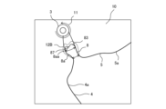
- FIG. 8 is a front view showing the configuration of the stress dispersing section 8 provided in the axial fan 10 according to the first embodiment.
- a dashed line shown in FIG. 8 is an imaginary line 7aA indicating the position of the ridgeline 7a of the connecting portion 7 described in the comparative example shown in FIGS. As shown in FIG.
- the virtual line 7aA is, for example, the leading edge portion of the circumferentially adjacent blade 1 located rearward in the rotational direction 11 among the ridgelines 5a of the trailing edge portion 5 of the blade 1 in a front view.
- a virtual line obtained by smoothly extending the edge line 5a near the edge 4 may also be used.
- the region on the inner peripheral side of the imaginary line 7aA is the formation range of the connecting portion 7 (see arrow 24 in FIG. 15).
- the stress dispersion part 8 is a notch formed in the connection part 7.
- the blades 1 and the connecting portion 7 of the axial fan 10 are molded of resin by, for example, injection molding. Therefore, the stress dispersion portion 8 can be molded at the same time when the blade 1 and the connection portion 7 are injection molded.
- the stress dispersing portion 8 may be formed on the connecting portion 7 after the blade 1 and the connecting portion 7 are molded.
- the stress dispersing portion 8 is a substantially U-shaped recess that is recessed inwardly from an outer peripheral end portion 71 forming a ridgeline 7a on the outer peripheral side of the connecting portion 7 .
- the stress dispersion portion 8 penetrates through the plate thickness of the connection portion 7 .
- the stress dispersion portion 8 includes an opening 81 , a constricted portion 82 and a bottom portion 83 .
- the total radial length of the stress dispersion portion 8 is defined as "length La". That is, the length La is the radial length from the opening 81 to the bottom 83 of the stress dispersion portion 8 . Since the stress dispersion portion 8 is composed of the cut portion formed so as to penetrate the plate thickness of the connection portion 7 in this way, the region in which the stress dispersion portion 8 is formed is discontinuous in the connection portion 7. become part.
- the opening 81 is formed at the position of an imaginary line 7aA indicating the position of the ridgeline 7a of the connecting portion 7 described in the comparative example shown in FIGS.
- the opening 81 is formed over the entire circumferential length of the imaginary line 7aA, but is not limited to this. That is, the opening 81 may be formed only in a portion of the imaginary line 7aA. However, in that case, the portion indicated by the imaginary line 7aA adjacent to the opening 81 of the stress dispersion portion 8 becomes the shoulder portion. In that case, the wind hits the shoulder, turbulence occurs in the flow of wind, and pressure loss occurs. Therefore, it is desirable that the opening 81 is formed over the entire circumferential length of the imaginary line 7aA.
- the ridgeline of the stress dispersing portion 8 the ridgeline 4a of the leading edge portion 4 and the ridgeline 5a of the trailing edge portion 5 of the blade 1 are smoothly connected in the vicinity of the opening 81. It will be. Thereby, the pressure loss of the wind near the opening 81 can be suppressed.
- the bottom part 83 is the deepest part of the stress dispersion part 8 . That is, the bottom portion 83 is the portion closest to the fan shaft 2 in the stress distribution portion 8 .
- the bottom portion 83 radially faces the opening portion 81 .
- the deep side portion of the stress dispersion portion 8 including the bottom portion 83 constitutes an arc portion 84 formed in an arc shape.
- the ridgeline of the arc portion 84 has, for example, a semicircular shape or a substantially semicircular shape.
- the ridgeline of the arc portion 84 is formed in a curved shape having one curvature or multiple curvatures.
- the constricted portion 82 is formed between the opening portion 81 and the bottom portion 83 in the radial direction.
- the constricted portion 82 is a portion constricted inward in the circumferential direction. Therefore, the circumferential length of the constricted portion 82 is smaller than the circumferential lengths of the arc portion 84 and the opening portion 81 . That is, among the "intervals Lint between ridgelines" in the entire stress dispersion portion 8, the "interval Lint between ridgelines” in the constricted portion 82 is the smallest.
- a first inclined portion 85 is provided between the arc portion 84 and the constricted portion 82 .
- the first inclined portion 85 is formed in a tapered shape.
- a region of the stress distribution portion 8 from the arc portion 84 formed by the first inclined portion 85 to the constricted portion 82 is hereinafter referred to as a first region 91 .
- the first region 91 is a region in which the “interval between ridge lines Lint” decreases toward the outer circumference in the radial direction.
- a second inclined portion 86 is provided between the constricted portion 82 and the opening portion 81 .
- the second inclined portion 86 is tapered in the opposite direction, that is, the “interval between ridges Lint” gradually increases from the constricted portion 82 toward the opening 81 .
- a region of the stress dispersion portion 8 from the constricted portion 82 formed by the second inclined portion 86 to the opening 81 is hereinafter referred to as a second region 92 .
- the second region 92 is a region in which the "interval between ridge lines Lint" increases toward the radially outer peripheral side.
- the boundary between the first region 91 and the second region 92 is a constricted portion 82 .
- the area of the arc portion 84 is referred to as a third area 93 of the stress dispersion portion 8.
- the third region 93 is a region in which the “interval between ridge lines Lint” gradually increases from the bottom portion 83 toward the outer peripheral side in the radial direction.
- the ridgeline of the entire substantially U-shaped stress dispersion portion 8 including the ridgeline of the first region 91, the ridgeline of the second region 92, and the ridgeline of the third region 93 is referred to as the ridgeline of the stress dispersion portion 8.
- the "interval between ridgelines Lint" in the stress dispersion portion 8 may be called a first interval between ridgelines.
- FIG. 9 is an explanatory diagram showing changes in the radial direction of the interval Lint between the ridgelines in the stress dispersion portion 8 in the axial fan 10 according to the first embodiment.
- the vertical axis indicates the interval Lint between the ridge lines
- the horizontal axis indicates the ratio of the radius r of the concentric circles to the radius r1.
- the interval Lint between the ridge lines gradually decreases toward the outer circumference in the radial direction.
- the second region 92 it can be seen that the interval Lint between the ridge lines gradually increases toward the radially outer peripheral side.
- the rate of change (absolute value of rate of decrease) of the interval Lint between ridges in the first region 91 is smaller than the rate of change (absolute value of rate of increase) in the second region 92 .
- the distance Lint between the ridge lines gradually increases toward the outer circumference in the radial direction.
- the rate of change (absolute value of rate of decrease) of the interval Lint between ridge lines in the first region 91 is smaller than the rate of change (absolute value of rate of increase) in the third region 93 .
- FIG. 10 is a partial front view showing a configuration of a modification of axial fan 10 according to the first embodiment.
- the interval Lint between the ridgelines in the first region 91 is constant. That is, in FIG. 10, the stress dispersion portion 8 has a linear portion 85A instead of the first inclined portion 85. As shown in FIG. The pair of linear portions 85A are arranged so as to be parallel to each other. In the first region 91 composed of the straight portion 85A, the interval Lint between the ridgelines does not change and is constant.
- the stress dispersion portion 8 acts in the same manner as the stress dispersion portion 8 according to the first embodiment, so that the same effects as in the first embodiment can be obtained. Effects of the first embodiment will be described below.
- FIG. 11A and 11B are diagrams for explaining the stress distribution effect in the axial fan 10 according to the first embodiment.
- FIG. The axial fan 10 rotates in a rotation direction 11 with the fan shaft 2 as a central axis.
- the blade 1 is deformed by the centrifugal force generated when the axial fan 10 rotates.
- a two-dot chain line 5aA indicates the position of the ridgeline 5a when the blade 1 is deformed
- a two-dot chain line 4aA indicates the position of the ridgeline 4a when the blade 1 is deformed.
- the centrifugal force generated when the axial fan 10 rotates deforms the blade 1 in the direction in which the interval Lint between the ridge lines increases.
- the stress dispersion portion 8 is provided in the connection portion 7 .
- stress is generated in the region 12A along the ridge line 8a of the stress dispersion portion 8. As shown in FIG.
- the stress dispersion portion 8 is formed by notching the ridgeline 7a of the connection portion in a substantially U shape, the length of the ridgeline 8a of the stress dispersion portion 8 is equal to the length of the ridgeline 7a of the connection portion of the comparative example. big in comparison. Therefore, the range of the region 12A along the ridgeline 8a of the stress dispersion portion 8 is wider than the range of the region 12 along the ridgeline 7a of the connecting portion 7 of the comparative example. Therefore, the stress concentrated in the region 12 of the comparative example in FIG. 7 is dispersed over the entire region 12A, which is wider than the region 12. Therefore, in the first embodiment, the stress concentration is suppressed as compared with the comparative example. be able to.
- the constricted portion 82 is provided in the stress dispersion portion 8 , an increase in the interval Lint between the ridgelines when the blade 1 is deformed can be suppressed, so the strength of the connection portion 7 can be ensured.
- the first region 91 is provided on the inner peripheral side of the constricted portion 82 .
- the interval Lint between the ridge lines gradually decreases toward the radially outer peripheral side. Therefore, a force in the opposite direction is applied by the first region 91 to the stress applied in the direction in which the interval Lint between the ridge lines increases as indicated by the two-dot chain lines 4aA and 5aA in FIG. 11, and the stress is canceled. be.
- a stress dispersion effect in the first region 91 can be expected. That is, the stress can be dispersed by providing the first inclined portion 85 (see FIG. 8) or the straight portion 85A (see FIG. 10) that constitutes the first region.
- the second region 92 is provided on the outer peripheral side of the first region 91.
- the interval Lint between the ridge lines gradually increases toward the radially outer peripheral side.
- the stress concentration factor is the ratio of the locally generated highest stress to the average stress (also referred to as nominal stress) of the target cross section.
- a third region 93 composed of the arc portion 84 is provided on the inner peripheral side of the first region.
- the arc portion 84 has a semicircular shape or a substantially semicircular shape.
- the stress concentration factor can be reduced. If the diameter Lb (see FIG. 11) of the arc portion 84 is too large or too small with respect to the radial length La (see FIG. 8) of the stress dispersion portion 8, the stress dispersion effect is reduced. do. Therefore, it is desirable that the diameter Lb of the arc portion 84 is about 1/2 to 1/3 of the radial length La of the stress dispersion portion 8 (see FIG. 8).
- the circular arc portion 84 is formed in a curved shape, it is smoothly connected to the ridgeline of the first region 91 . Therefore, concentration of stress can be suppressed.
- the arrow 9 indicates the airflow flowing on the front surface of the blade 1 when the blade 1 rotates.
- the front surface of the blade 1 is the surface of the surface of the blade 1 that pushes the airflow, that is, the stress surface.
- the arrow 9 indicates the airflow flowing on the front surface of the blade 1 when the blade 1 rotates.
- the airflow along the front surface of blade 1 generally flows in the same manner from leading edge 4 to trailing edge 5. .
- Embodiment 1 as shown in FIG. Therefore, as shown in the graph of FIG.
- the interval Lint between the ridge lines is the same as that of the other portion from the opening 81 to the outer peripheral edge portion 6. is significantly reduced compared to As a result, when the airflow passes through a narrow gap, the speed of the airflow is increased, so that the work of the blades 1 in the first to third regions 91 to 93 where the stress dispersing portion 8 is provided acts greatly on the entire airflow. become. As a result, as indicated by the arrow 9 in FIG. 1, the area where the stress dispersing portion 8 is provided draws the airflow from the vicinity of the outer peripheral side of the blade 1 .
- the inflow of air to the inner peripheral side of the blades 1 can be promoted.
- the greater the flow rate of the air flowing toward the inner periphery of the axial fan the higher the blowing efficiency. Therefore, in Embodiment 1, the provision of the stress dispersing section 8 also has the effect of increasing the blowing efficiency.
- FIG. 12 is a partially enlarged side view for explaining the airflow in the connecting portion 7 of the axial fan 10 according to Embodiment 1.
- FIG. FIG. 13 is a partially enlarged front view for explaining the airflow at the connecting portion 7 of the axial fan 10 according to the first embodiment. 12 and 13, the arrow 20 indicates the ridgeline of the connecting portion 7 connected to the ridgeline 5a of the trailing edge portion 5, that is, the ridgeline 8a of the stress dispersion portion 8 connected to the ridgeline 5a of the trailing edge portion 5 (hereinafter referred to as , a ridgeline 8a on the trailing edge 5 side).
- the arrow 21 indicates the ridgeline of the connecting portion 7 connected to the ridgeline 4a of the front edge portion 4, that is, the ridgeline 8a of the stress dispersing portion 8 connected to the ridgeline 4a of the front edge portion 4 (hereinafter referred to as the front edge portion 4a).
- 8a) shows the airflow on the side ridgeline 8a).
- the airflow bends in the height direction Z (see FIG. 22) or in the axial direction S in the downstream direction.
- the direction of the air current that was headed changes to head upstream. That is, as indicated by arrow 20, the direction of the airflow changes from the front surface of blade 1 toward the back surface.
- the airflow bends in the height direction Z (see FIG. 22), or in the axial direction S,
- the direction of the airflow going upstream changes to go downstream. That is, as indicated by an arrow 21, the direction of the airflow changes from the back surface of the blade 1 toward the front surface.
- the air currents flow in different directions near the edge line 8a on the front edge portion 4 side and the edge line 8a on the rear edge portion 5 side. That is, since the airflow is split between the leading edge portion 4 side and the trailing edge portion 5 side in the stress dispersing portion 8 configured by the cut portion, the airflow is divided and the blade 1 receives stress from the airflow. is reduced. As a result, the stress on the blade 1 generated by the airflow is reduced, and the amount of deformation of the blade 1 is reduced.
- FIG. 14 and 15 are explanatory diagrams explaining the shape of the blade 1 of the axial fan 10 according to the first embodiment.
- FIG. 14 shows a front view of the axial fan 10 according to Embodiment 1.
- a point O indicates the position of the fan shaft 2.
- points A, B, and C are three points on the outer peripheral edge 6 of the blade 1, respectively. Of the three points, point A is the closest to the leading edge 4 and point C is the closest to the trailing edge 5 .
- a point B is a point between the points A and C.
- a cross section 30 in FIG. 15 is a cross section along the straight line AO connecting points A and O in FIG.
- a cross section 31 in FIG. 15 is a cross section along the BO straight line connecting points B and O in FIG.
- a cross section 32 in FIG. 15 is a cross section along the CO straight line connecting points C and O in FIG. 15, point 30a indicates the most upstream position in cross section 30, point 31a indicates the most upstream position in cross section 31, and point 32a indicates the most upstream position in cross section 32. ing.
- arrows 22 indicate airflows generated by the rotation of the axial fan 10 .
- an arrow 24 indicates a formation range of the connecting portion 7 in the axial fan 10.
- the radial length La (see FIG. 8) of the stress dispersion portion 8 is half the radius r0 (see FIG. 4) of the formation range of the connecting portion 7, or Greater than 1/2 is desirable.
- the stress generated when the axial fan 10 rotates can be dispersed by providing the stress dispersing portion 8 in the connecting portion 7 . Therefore, stress concentration on the connecting portion 7 can be suppressed, so that damage to the blade 1 and damage to the connecting portion 7 can be prevented even when subjected to strong winds such as typhoons.
- the stress dispersing portion 8 is provided, the inflow of the airflow to the inner peripheral side of the axial fan 10 can be promoted, so that the air blowing function can be improved.
- the effect of weight reduction which is an advantage of bossless design, can be maintained.
- both the advantages of bossless design that is, weight reduction of the axial fan 10 and improvement of the blowing efficiency
- maintenance of the strength of the blades 1 are achieved. be able to.
- FIG. 16 is a partial front view showing the configuration of axial fan 10 according to the second embodiment.
- the difference from the first embodiment shown in FIG. 8 is that a convex portion 87 is formed on the bottom portion 83 of the stress dispersion portion 8 in FIG. Since other configurations are the same as those of the first embodiment, they are denoted by the same reference numerals, and descriptions thereof are omitted here.
- the convex portion 87 is formed on the bottom portion 83 of the stress dispersion portion 8 .
- the convex portion 87 protrudes from the bottom portion 83 of the stress dispersion portion 8 toward the outer peripheral side.
- the ridgeline 8a of the convex portion 87 portion is called a ridgeline 8aa
- the ridgeline 8aa of the convex portion 87 is formed in a curved shape having one curvature or multiple curvatures.
- the blades 1 and the connecting portion 7 of the axial fan 10 are molded of resin by, for example, injection molding.
- the stress dispersing portion 8 having the convex portion 87 can be easily molded at the same time when the blade 1 and the connecting portion 7 are injection molded.
- the stress dispersing portion 8 having the convex portion 87 may be formed on the connecting portion 7 after the blade 1 and the connecting portion 7 are molded.
- FIG. 17 is a reference diagram showing an example of how stress is dispersed in the stress dispersion portion 8 of the axial fan 10 according to the first embodiment.
- FIG. 18 is an explanatory diagram showing an example of how stress is dispersed in the stress dispersion portion 8 of the axial fan 10 according to the second embodiment.
- a region 12B is a region along the ridge line 8a of the stress dispersion portion 8 and responsible for stress dispersion. That is, in the second embodiment, the stress generated when axial fan 10 rotates is distributed over entire region 12B. A detailed description will be given below.
- the stress during rotation of the axial fan 10 is distributed over the entire region 12A.
- a region 12A is a region along the ridgeline 8a of the stress dispersion portion 8.
- the stress is not uniformly distributed throughout the region 12A as in the region 12A shown in the reference diagram of FIG. It is assumed that bias may occur.
- FIG. 17 more stress is applied to the region 12AA than the other portions of the region 12A.
- the region 12AA is the portion closest to the shaft support portion 3 in the region 12A.
- a convex portion 87 is formed on the bottom portion 83 of the stress dispersion portion 8 .
- the ridge line 8a of the stress dispersion portion 8 increases toward the radially outer peripheral side at the bottom portion 83 . That is, the ridgeline 8a of the second embodiment is longer than the ridgeline 8a of the first embodiment by the addition of the ridgeline 8aa portion of the convex portion 87 .
- the ridgeline 8aa is formed in a curved shape and smoothly connected to other portions of the ridgeline 8a. That is, the ridgeline 8a is gently connected to the ridgeline 8a of the first region 91 (see FIG. 10) of the stress dispersion portion 8. As shown in FIG.
- the length of the entire ridgeline 8a is increased by the amount of formation of the convex portion 87, and the region responsible for dispersing the stress is larger than that in the first embodiment. also expand further. Therefore, in the second embodiment, a further effect of dispersing stress can be obtained as compared with the first embodiment.
- the stress dispersing portion 8 As described above, in the axial fan 10 according to the second embodiment, as in the first embodiment, by providing the stress dispersing portion 8, there is an advantage of being bossless (that is, weight reduction of the axial fan 10). and improvement of air blowing efficiency) and maintenance of the strength of the blade 1 can be made compatible. Furthermore, in the second embodiment, since the convex portion 87 is provided on the bottom portion 83 of the stress dispersion portion 8, the length of the ridgeline 8a of the stress dispersion portion 8 is increased by that amount. As a result, the area responsible for dispersing the stress is further expanded, and a further stress dispersing effect can be obtained as compared with the first embodiment.
- FIG. 19 is a partial front view showing the configuration of axial fan 10 according to the third embodiment.
- the interval Lint between the ridgelines in the constricted portion 82 of the stress dispersion portion 8 is 0 mm. That is, in Embodiment 1, the interval Lint between the ridgelines in the constricted portion 82 of the stress dispersion portion 8 was a value larger than 0 mm, but in Embodiment 3, the ridgelines in the constricted portion 82 are connected to each other, and the interval Lint is 0 mm. That is, the constricted portion 82 serves as a connecting portion.
- the portions of the arc portion 84 and the first inclined portion 85 serve as through holes formed in the connection portion 7 .
- the interval Lint between the ridgelines in the constricted portion 82 may be 0 mm or more.
- Embodiment 3 instead of the stress dispersion portions 8 formed from cuts described in Embodiments 1 and 2, stress dispersion portions 8A formed from through holes are provided. .
- the stress dispersion portion 8A is composed of a through hole 88, a constricted portion 82 that is a connecting portion, a second inclined portion 86, and an opening portion 81.
- the stress dispersion portion 8A is formed by making a portion of the connecting portion 7 formed of a continuous surface discontinuous. Since other configurations are the same as those of the first embodiment, they are denoted by the same reference numerals, and descriptions thereof are omitted here.
- Embodiment 3 the perimeters of the through hole 88, the second inclined portion 86, and the opening 81 form the ridgeline 8a of the stress dispersion portion 8A. Therefore, the stress during rotation of the axial fan 10 is dispersed over the entire area along the ridgeline 8a of the stress dispersion portion 8A. Therefore, in the third embodiment as well, effects similar to those of the first and second embodiments can be obtained.
- FIG. 20 is a partial front view showing a configuration of a modification of the axial fan 10 according to Embodiment 3.
- the stress distribution portion 8A may include a plurality of through holes 88.
- the stress dispersion portion 8A is arranged in the connection portion 7.
- the through holes 88 may be arranged radially in the connecting portion 7 as shown in FIG.
- the sizes of the plurality of through holes 88 may not be the same. Specifically, as shown in FIG.
- the through hole 88 on the outer peripheral side may be the largest, and the size of the through hole 88 may gradually decrease from the outer peripheral side toward the inner peripheral side.
- the stress dispersion portion 8A is composed only of a plurality of through holes 88.
- the stress dispersion portion 8A does not include the second inclined portion 86 and the opening portion 81.
- the stress during rotation of the axial fan 10 is distributed over the entire area along the outer periphery of the plurality of through holes 88 .
- the stress dispersing portion 8A constituted by the through hole 88 is provided in the connecting portion 7, so that the stress generated when the axial fan 10 rotates is distributed over the entire connecting portion 7.
- the axial flow fan 10 according to Embodiment 3 also provides the same effects as Embodiments 1 and 2. That is, in Embodiment 3, the provision of the stress dispersing portion 8A provides advantages of bossless design (that is, reduction in weight of the axial flow fan 10 and improvement in the blowing efficiency) and maintenance of the strength of the blade 1. can be made compatible.
- Embodiment 4 As described above, the axial fans 10 according to Embodiments 1 to 3 relate to stress dispersion of bossless axial fans. Air flow can be increased. In addition, if installed in air conditioners or hot water supply outdoor units, which are refrigeration cycle devices consisting of compressors and heat exchangers, etc., it will be possible to increase the amount of air passing through the heat exchangers with high efficiency, resulting in energy savings for the equipment. can be realized.
- Embodiment 4 describes a case where the axial flow fan 10 of Embodiments 1 to 3 is applied to an outdoor unit of an air conditioner as an outdoor unit including a blower as an example.
- FIG. 21 is a schematic diagram of an air conditioner, which is a refrigeration cycle device according to Embodiment 4.
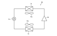
- the air conditioner includes a refrigerant circuit 70 in which a compressor 64, a condenser 72, an expansion valve 74, and an evaporator 73 are connected in order by refrigerant pipes.
- a condenser fan 72 a is arranged in the condenser 72 .
- the condenser fan 72 a blows air for heat exchange to the condenser 72 .
- An evaporator fan 73 a is arranged in the evaporator 73 .
- the evaporator fan 73 a blows air for heat exchange to the evaporator 73 .
- At least one of the condenser fan 72a and the evaporator fan 73a is configured by the axial fan 10 according to any one of the first to third embodiments.
- the refrigerant circuit 70 may be provided with a four-way valve or the like for switching the flow of the refrigerant to switch between the heating operation and the cooling operation.
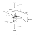
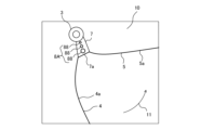
- FIG. 22 is a perspective view of an outdoor unit as an example of the blower according to Embodiment 4, viewed from the outlet side.
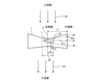
- FIG. 23 is a diagram for explaining the configuration of the outdoor unit shown in FIG. 22 from the top side. 22 and 23, X is the width direction, Y is the depth direction, and Z is the height direction. Note that the height direction Z is, for example, a vertical direction or a substantially vertical direction.
- the outdoor unit main body 51 which is a casing, is configured as a housing having a pair of left and right side surfaces 51a and 51c, a front surface 51b, a rear surface 51d, a top surface 51e and a bottom surface 51f.
- the side surface 51a and the rear surface 51d have openings for sucking air from the outside.
- the front panel 52 is formed with a blowout port 53 as an opening portion for blowing out air to the outside.
- the air outlet 53 is covered with a fan grill 54, thereby preventing contact between external objects and the like and the axial flow fan 10 for safety.
- Arrows 22 and 22A in FIG. 23 indicate the flow of air.
- An axial fan 10 is installed inside the outdoor unit main body 51 .
- the axial fan 10 is connected via a drive shaft 62 to a fan motor 61, which is a drive source, on the rear surface 51d side.
- the axial fan 10 is driven by a fan motor 61 to drive it.
- the drive shaft 62 extends in a direction perpendicular to the height direction Z. As shown in FIG.
- the drive shaft 62 extends in the depth direction Y in the example of FIG.
- the interior of the outdoor unit main body 51 is divided by a partition plate 51g, which is a wall body, into a blowing chamber 56 in which the axial flow fan 10 is installed and a machine room 57 in which the compressor 64 and the like are installed.
- a heat exchanger 68 extending in a substantially L shape in a plan view is provided on the side 51a side and the rear side 51d side in the blowing chamber 56 .
- the heat exchanger 68 functions as a condenser 72 during cooling operation, and functions as an evaporator 73 during heating operation.
- a bell mouth 63 is arranged radially outside the axial flow fan 10 arranged in the blowing chamber 56 .
- the bellmouth 63 is located outside the outer peripheral edge of the blade 1 and has an annular shape along the rotational direction of the axial fan 10 .
- the partition plate 51g is positioned on one side of the bell mouth 63, and part of the heat exchanger 68 is positioned on the other side.
- the front end of the bell mouth 63 is connected to the front panel 52 of the outdoor unit so as to surround the outer periphery of the outlet 53 .
- the bell mouth 63 may be configured integrally with the front panel 52, or may be prepared separately and joined thereto.
- the bell mouth 63 configures a flow path between the suction side and the blow-out side of the bell mouth 63 as an air path near the blow-out port 53 . That is, the air passage near the blower outlet 53 is separated from the other space in the blower chamber 56 by the bell mouth 63 .
- the heat exchanger 68 provided on the suction side of the axial fan 10 includes a plurality of fins arranged side by side so that the plate-like surfaces are parallel, and a heat transfer tube passing through each fin in the direction of the parallel arrangement. It has Refrigerant circulating in the refrigerant circuit flows through the heat transfer tubes.
- the heat exchanger 68 according to Embodiment 4 is configured such that the heat transfer tubes extend in an L shape from the side surface 51a to the back surface 51d of the outdoor unit main body 51, and the heat transfer tubes in multiple stages meander while penetrating the fins. be.
- the heat exchanger 68 is connected to the compressor 64 via a pipe 65 or the like, and is further connected to an indoor heat exchanger and an expansion valve (not shown) to form a refrigerant circuit 70 of the air conditioner.
- a circuit board box 66 is arranged in the machine room 57, and equipment mounted in the outdoor unit is controlled by a control circuit board (not shown) provided in the circuit board box 66.
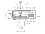
- FIG. 24 is a perspective view showing the configuration of an outdoor unit as an example of the blower according to Embodiment 5.
- FIG. 25 is a partial cross-sectional view for explaining the configuration of the outdoor unit shown in FIG. 24.
- the axial flow fan 10 according to Embodiments 1 to 3 can be applied to a top-flow type outdoor unit that blows air upward, such as an outdoor unit of a large air conditioner for a building.
- a top-flow type outdoor unit that blows air upward
- the fan motor 61 as a drive source is arranged vertically below the axial fan 10 .
- a drive shaft 62 of the fan motor 61 extends vertically or substantially vertically.
- the axial fan 10 is connected via a drive shaft 62 to a fan motor 61 which is a drive source.
- the axial fan 10 is rotationally driven by a driving force applied by a fan motor 61 .
- the outdoor unit according to Embodiment 5 has main body case 101, which is a casing. ), an expansion valve 74 (see FIG. 21) and an accumulator.
- the main body case 101 has, for example, a substantially rectangular parallelepiped shape, and is formed with intake portions 104a for sucking air on four side surfaces 104 and a blowout portion 109 for blowing air on the upper surface.
- the outdoor unit according to Embodiment 5 blows out the air sucked from the side surface from the upper surface.
- the lower part of the main body case 101 is covered with an opening/closing panel 102A, a left side lower panel 102B, a rear lower panel (not shown), and a right side lower panel (not shown). forms a machine room 103 in which is housed.
- a heat exchange chamber 105 in which a heat exchanger 107 is accommodated is formed above the mechanical chamber 103 of the main body case 101 .
- the heat exchanger 107 provided on the suction side of the axial flow fan 10 includes a plurality of fins arranged in parallel so that their plate-like surfaces are parallel, and a heat transfer tube passing through each fin in the arrangement direction. It has The heat exchanger 107 functions as a condenser 72 (see FIG. 21) during cooling operation, and functions as an evaporator 73 (see FIG. 21) during heating operation.
- the heat exchanger 107 is connected to the compressor 64 (see FIG. 21) via piping or the like, and is further connected to an indoor heat exchanger, an expansion valve, etc.
- the heat exchangers 107 are arranged to face each of the four side surfaces 104 of the body case 101, but are not limited to this. That is, the heat exchanger 107 may be arranged to face at least one of the four side surfaces 104 of the body case 101 .
- a bell mouth 106 is formed in the upper portion of the heat exchange chamber 105 of the main body case 101.
- the bell mouth 106 has a cylindrical shape, and is formed with a blowout portion 109 for blowing air upward.
- the axial fan 10 is housed inside the bell mouth 106 .
- a fan guard portion 110 that covers the upper portion of the axial fan 10 is attached to the bell mouth 106 .
- the fan guard portion 110 is fixed to the bell mouth 106 at its outer peripheral portion.
- Embodiments 4 and 5 have been described by taking the outdoor unit as an example of the blower. Further, the outdoor unit is exemplified by an outdoor unit of an air conditioner. However, the disclosure is not so limited.
- the fans according to Embodiments 4 and 5 can be implemented as indoor units of air conditioners. Moreover, it is also possible to implement it as an outdoor unit or an indoor unit of other refrigerating cycle apparatus such as a water heater instead of an air conditioner.
- the blowers according to Embodiments 4 and 5 can be applied to various air blowing devices such as ventilation fans and ventilators. Thus, the blowers according to Embodiments 4 and 5 can be applied to devices or equipment other than the outdoor unit.
- the axial fans 10 shown in Embodiments 1 to 3 are applicable to blowers in general and refrigeration cycle devices in general.
Abstract
Un ventilateur axial comprend une pluralité d'aubes tournant autour d'un axe du ventilateur, et une partie de liaison plane formée autour de l'axe du ventilateur et reliant des aubes circonférentiellement adjacentes parmi la pluralité d'aubes. La partie de liaison comporte une partie discontinue, et la partie discontinue forme une section de distribution de contrainte destinée à distribuer la contrainte appliquée à la partie de liaison lors de la rotation de la pluralité d'aubes.
Priority Applications (2)
| Application Number | Priority Date | Filing Date | Title |
|---|---|---|---|
| JP2023567275A JPWO2023112077A1 (fr) | 2021-12-13 | 2021-12-13 | |
| PCT/JP2021/045745 WO2023112077A1 (fr) | 2021-12-13 | 2021-12-13 | Ventilateur axial, soufflante et dispositif à cycle frigorifique |
Applications Claiming Priority (1)
| Application Number | Priority Date | Filing Date | Title |
|---|---|---|---|
| PCT/JP2021/045745 WO2023112077A1 (fr) | 2021-12-13 | 2021-12-13 | Ventilateur axial, soufflante et dispositif à cycle frigorifique |
Publications (1)
| Publication Number | Publication Date |
|---|---|
| WO2023112077A1 true WO2023112077A1 (fr) | 2023-06-22 |
Family
ID=86773939
Family Applications (1)
| Application Number | Title | Priority Date | Filing Date |
|---|---|---|---|
| PCT/JP2021/045745 WO2023112077A1 (fr) | 2021-12-13 | 2021-12-13 | Ventilateur axial, soufflante et dispositif à cycle frigorifique |
Country Status (2)
| Country | Link |
|---|---|
| JP (1) | JPWO2023112077A1 (fr) |
| WO (1) | WO2023112077A1 (fr) |
Citations (4)
| Publication number | Priority date | Publication date | Assignee | Title |
|---|---|---|---|---|
| JP5100671B2 (ja) * | 2009-01-23 | 2012-12-19 | 三菱電機株式会社 | プロペラ羽根の製造方法、プロペラ羽根及び送風機 |
| JP6505028B2 (ja) * | 2015-03-30 | 2019-04-24 | 三菱電機株式会社 | 羽根車 |
| JP2019090418A (ja) * | 2014-08-07 | 2019-06-13 | 三菱電機株式会社 | 軸流ファン、及び、その軸流ファンを有する空気調和機 |
| CN211082379U (zh) * | 2019-10-09 | 2020-07-24 | 佛山市启正电气有限公司 | 扇叶安装盘、扇叶安装结构和吊扇 |
-
2021
- 2021-12-13 JP JP2023567275A patent/JPWO2023112077A1/ja active Pending
- 2021-12-13 WO PCT/JP2021/045745 patent/WO2023112077A1/fr active Application Filing
Patent Citations (4)
| Publication number | Priority date | Publication date | Assignee | Title |
|---|---|---|---|---|
| JP5100671B2 (ja) * | 2009-01-23 | 2012-12-19 | 三菱電機株式会社 | プロペラ羽根の製造方法、プロペラ羽根及び送風機 |
| JP2019090418A (ja) * | 2014-08-07 | 2019-06-13 | 三菱電機株式会社 | 軸流ファン、及び、その軸流ファンを有する空気調和機 |
| JP6505028B2 (ja) * | 2015-03-30 | 2019-04-24 | 三菱電機株式会社 | 羽根車 |
| CN211082379U (zh) * | 2019-10-09 | 2020-07-24 | 佛山市启正电气有限公司 | 扇叶安装盘、扇叶安装结构和吊扇 |
Also Published As
| Publication number | Publication date |
|---|---|
| JPWO2023112077A1 (fr) | 2023-06-22 |
Similar Documents
| Publication | Publication Date | Title |
|---|---|---|
| AU2006298249B2 (en) | Centrifugal fan and air conditioner using the same | |
| JP5235867B2 (ja) | シロッコファン及び空気調和装置 | |
| CN106481574B (zh) | 离心式风机和包括其的空调机 | |
| JP5079063B2 (ja) | プロペラおよび送風機並びにヒートポンプ装置 | |
| JP2007107435A (ja) | ターボファン及びこれを用いた空気調和機 | |
| JP6611676B2 (ja) | 送風機および冷凍サイクル装置の室外機 | |
| CN110506164B (zh) | 螺旋桨式风扇及空调装置用室外机 | |
| JP2007205268A (ja) | 遠心ファン | |
| CN110914553B (zh) | 叶轮、送风机及空调装置 | |
| EP3667097B1 (fr) | Ventilateur hélicoïdal, dispositif du type soufflante et dispositif à cycle de réfrigération | |
| WO2023112077A1 (fr) | Ventilateur axial, soufflante et dispositif à cycle frigorifique | |
| JP4937331B2 (ja) | 送風機及びヒートポンプ装置 | |
| JPH0539930A (ja) | 空気調和装置 | |
| KR100468468B1 (ko) | 공기조화기의 실내기 | |
| JP6710337B2 (ja) | 空気調和機 | |
| KR101996052B1 (ko) | 공기조화기 | |
| WO2015063850A1 (fr) | Ventilateur tangentiel et climatiseur | |
| JP7337308B1 (ja) | 羽根車、送風機及び空気調和機 | |
| WO2023084652A1 (fr) | Ventilateur à flux transversal, dispositif de soufflage et dispositif à cycle de réfrigération | |
| WO2023223383A1 (fr) | Ventilateur à flux transversal, dispositif de soufflage, et dispositif à cycle de réfrigération | |
| WO2024089808A1 (fr) | Ventilateur à écoulement axial, souffleuse d'air et dispositif de conditionnement d'air | |
| WO2024009490A1 (fr) | Ventilateur à écoulement axial, souffleuse d'air et dispositif de conditionnement d'air | |
| KR100459129B1 (ko) | 천장형 공기조화기의 실내기 | |
| US20220325905A1 (en) | Air handling unit and fan therefor | |
| JP6625213B2 (ja) | 多翼ファン及び空気調和機 |
Legal Events
| Date | Code | Title | Description |
|---|---|---|---|
| 121 | Ep: the epo has been informed by wipo that ep was designated in this application |
Ref document number: 21968000 Country of ref document: EP Kind code of ref document: A1 |
|
| WWE | Wipo information: entry into national phase |
Ref document number: 2023567275 Country of ref document: JP |