WO2023106050A1 - 発光装置および電子機器 - Google Patents
発光装置および電子機器 Download PDFInfo
- Publication number
- WO2023106050A1 WO2023106050A1 PCT/JP2022/042416 JP2022042416W WO2023106050A1 WO 2023106050 A1 WO2023106050 A1 WO 2023106050A1 JP 2022042416 W JP2022042416 W JP 2022042416W WO 2023106050 A1 WO2023106050 A1 WO 2023106050A1
- Authority
- WO
- WIPO (PCT)
- Prior art keywords
- filter
- light
- transparent resin
- layer
- light emitting
- Prior art date
- Legal status (The legal status is an assumption and is not a legal conclusion. Google has not performed a legal analysis and makes no representation as to the accuracy of the status listed.)
- Ceased
Links
Images







Classifications
-
- H—ELECTRICITY
- H10—SEMICONDUCTOR DEVICES; ELECTRIC SOLID-STATE DEVICES NOT OTHERWISE PROVIDED FOR
- H10K—ORGANIC ELECTRIC SOLID-STATE DEVICES
- H10K59/00—Integrated devices, or assemblies of multiple devices, comprising at least one organic light-emitting element covered by group H10K50/00
- H10K59/30—Devices specially adapted for multicolour light emission
- H10K59/38—Devices specially adapted for multicolour light emission comprising colour filters or colour changing media [CCM]
-
- G—PHYSICS
- G02—OPTICS
- G02B—OPTICAL ELEMENTS, SYSTEMS OR APPARATUS
- G02B5/00—Optical elements other than lenses
- G02B5/20—Filters
-
- H—ELECTRICITY
- H05—ELECTRIC TECHNIQUES NOT OTHERWISE PROVIDED FOR
- H05B—ELECTRIC HEATING; ELECTRIC LIGHT SOURCES NOT OTHERWISE PROVIDED FOR; CIRCUIT ARRANGEMENTS FOR ELECTRIC LIGHT SOURCES, IN GENERAL
- H05B33/00—Electroluminescent light sources
- H05B33/12—Light sources with substantially two-dimensional [2D] radiating surfaces
-
- H—ELECTRICITY
- H10—SEMICONDUCTOR DEVICES; ELECTRIC SOLID-STATE DEVICES NOT OTHERWISE PROVIDED FOR
- H10K—ORGANIC ELECTRIC SOLID-STATE DEVICES
- H10K50/00—Organic light-emitting devices
-
- H—ELECTRICITY
- H10—SEMICONDUCTOR DEVICES; ELECTRIC SOLID-STATE DEVICES NOT OTHERWISE PROVIDED FOR
- H10K—ORGANIC ELECTRIC SOLID-STATE DEVICES
- H10K59/00—Integrated devices, or assemblies of multiple devices, comprising at least one organic light-emitting element covered by group H10K50/00
- H10K59/80—Constructional details
- H10K59/8791—Arrangements for improving contrast, e.g. preventing reflection of ambient light
- H10K59/8792—Arrangements for improving contrast, e.g. preventing reflection of ambient light comprising light absorbing layers, e.g. black layers
Definitions
- the present disclosure relates to a light-emitting device and an electronic device including the same.
- Light-emitting devices in which multiple OLED (Organic Light Emitting Diode) elements are two-dimensionally arranged are widely used.
- OLED Organic Light Emitting Diode
- color filters are provided on a substrate different from the substrate on which the plurality of OLED elements are arranged.
- misalignment occurs between the light-emitting element and the color filter during the manufacturing process of the light-emitting device, and the chromaticity tends to deviate. There was a problem of low efficiency.
- the color filter may peel off.
- the display characteristics of the light-emitting device may deteriorate.
- An object of the present disclosure is to provide a light-emitting device capable of suppressing peeling of color filters and an electronic device including the same.
- the light-emitting device includes a plurality of light emitting elements arranged two-dimensionally; a filter provided above the plurality of light emitting elements and including a plurality of color filter portions, At least one color filter portion of the plurality of color filter portions contains a transparent resin at the bottom.
- the light-emitting device is a plurality of light emitting elements arranged two-dimensionally; and a filter provided above the plurality of light emitting elements,
- the filter includes a filter portion containing transparent resin at the bottom.
- An electronic device includes the light emitting device according to the present disclosure.
- the multiple-color filter section may include three-color filter sections.
- One of the three-color filter sections may contain a transparent resin at the bottom, two of the three-color filter sections may contain a transparent resin at the bottom, or the three-color filter may contain transparent resin at the bottom.
- the part may contain a transparent resin on the bottom.
- the multi-color filter section may include three color filter sections, a red filter section, a green filter section, and a blue filter section.
- the red filter portion may include a transparent resin at the bottom
- the green filter portion of the three-color filter portions may include a transparent resin at the bottom
- the blue filter portion of the three-color filter portions may include a transparent resin at the bottom.
- the filter part may contain a transparent resin at the bottom.
- the red filter part and the green filter part among the three color filter parts may contain a transparent resin at the bottom
- the red filter part and the blue filter part among the three color filter parts may contain a transparent resin at the bottom
- the green filter part and the blue filter part may contain a transparent resin at the bottom.
- the three color filter parts namely the red filter part, the green filter part and the blue filter part, may contain a transparent resin at the bottom.
- the filter may include four types of filter sections, ie, a three-color filter section and an infrared transmission filter section.
- One of the four types of filter sections may contain a transparent resin in the bottom, two of the four types of filter sections may contain a transparent resin in the bottom, or four types of filters may be used.
- three types of filter sections may contain a transparent resin on the bottom, and four types of filter sections may contain a transparent resin on the bottom.
- the filter may include four types of filter units: a red filter unit, a green filter unit, a blue filter unit, and an infrared transmission filter unit.
- the red filter section may contain a transparent resin at the bottom
- the green filter section among the four types of filter sections may contain a transparent resin at the bottom
- the blue filter section among the four types may contain a transparent resin at the bottom.
- the filter part may contain transparent resin in the bottom part
- the infrared transmission filter part among the four types of filter parts may contain transparent resin in the bottom part.
- the red filter section and the green filter section may contain a transparent resin on the bottom, or the red filter section and the blue-green filter section of the four types of filter sections may contain a transparent resin on the bottom.
- the red filter section and the infrared transmission filter section may contain transparent resin on the bottom, or the green filter section and the blue filter section of the four types of filter sections may contain transparent resin on the bottom.
- the green filter portion and the infrared transmission filter portion among the four types of filter portions may contain a transparent resin on the bottom
- the blue filter portion and the infrared transmission filter portion among the four types of filter portions may contain a transparent resin on the bottom. It may contain a resin.
- the red filter section, the green filter section, and the blue filter section may include a transparent resin at the bottom.
- a transparent resin may be included in the bottom portion, or the red filter portion, the blue filter portion, and the infrared transmission filter portion among the four types of filter portions may include the transparent resin in the bottom portion, or the green filter portion may include the transparent resin in the bottom portion.
- the bottom portion of the portion, the blue filter portion and the infrared transmission filter portion may contain a transparent resin.
- Four kinds of filter parts, ie, a red filter part, a green filter part, a blue filter part and an infrared transmission filter part may contain a transparent resin at the bottom.
- the filter may include four color filter sections, ie, a red filter section, a green filter section, a blue filter section, and a cyan filter section.
- One of the four color filter portions may contain a transparent resin at the bottom, two of the four color filter portions may contain a transparent resin at the bottom, or four color filters may be included.
- the filter parts of three colors may contain a transparent resin on the bottom, and the filter parts of four colors may contain a transparent resin on the bottom.
- the filter may include four color filter sections, a red filter section, a green filter section, a blue filter section, and a magenta filter section.
- One of the four color filter portions may contain a transparent resin at the bottom, two of the four color filter portions may contain a transparent resin at the bottom, or four color filters may be included.
- the filter parts of three colors may contain a transparent resin on the bottom, and the filter parts of four colors may contain a transparent resin on the bottom.
- the filter may include five color filter units, a red filter unit, a green filter unit, a blue filter unit, a cyan filter unit, and a magenta filter unit.
- One of the five-color filter portions may contain a transparent resin at the bottom, two of the five-color filter portions may contain a transparent resin at the bottom, or the five-color filters may contain a transparent resin at the bottom.
- 3 color filter portions may contain a transparent resin in the bottom portion, 4 color filter portions out of the 5 color filter portions may contain a transparent resin in the bottom portion, or 5 color filter portions may contain a transparent resin in the bottom portion. It may contain a transparent resin.
- the filter may include two color filter portions, ie, a cyan color filter portion and a magenta color filter portion.
- one-color filter portion may include a transparent resin in the bottom portion
- two-color filter portions may include a transparent resin in the bottom portion.
- some of the plurality of specific color filter sections included in the display area may include a transparent resin at the bottom, and all of the plurality of specific color filter sections included in the display area may include the bottom section. may contain a transparent resin.
- the transparent resin may be present in a portion of the bottom of the filter section, or may be present in substantially the entire bottom of the filter section.
- the shape of the transparent resin is not particularly limited, and may be layered, granular, or amorphous, for example. Two or more shapes of transparent resin may be present at the bottom of the filter portion.
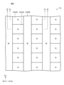
- FIG. 1 is a plan view showing an example of the configuration of the display device according to the first embodiment.
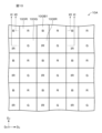
- FIG. 2 is a plan view showing an enlarged part of the display area of the display device according to the first embodiment.
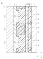
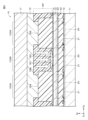
- FIG. 3 is a cross-sectional view taken along line III--III in FIG.
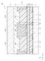
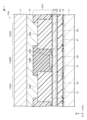
- FIG. 4 is a cross-sectional view taken along line IV--IV of FIG.
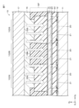
- FIG. 5 is a process chart for explaining an example of the method for manufacturing the display device according to the first embodiment.
- FIG. 6 is a process chart for explaining an example of the method for manufacturing the display device according to the first embodiment.
- FIG. 7 is a process chart for explaining an example of the method for manufacturing the display device according to the first embodiment.
- FIG. 8 is a process chart for explaining an example of the method for manufacturing the display device according to the first embodiment.
- FIG. 9 is a process chart for explaining an example of the method for manufacturing the display device according to the first embodiment.
- FIG. 10 is a plan view showing an enlarged part of the display area of the display device according to the second embodiment.
- 11 is a cross-sectional view taken along line XI-XI of FIG. 10.
- FIG. 12 is a cross-sectional view taken along line XII--XII in FIG. 10.
- FIG. 13 is a plan view showing an enlarged part of the display area of the display device according to the third embodiment.
- 14 is a cross-sectional view taken along line XIV--XIV in FIG. 13.
- FIG. 15 is a plan view showing an enlarged part of the display area of the display device according to the modification.
- FIG. 16 is a plan view showing an enlarged part of the display area of the display device according to the modification.
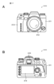
- FIG. 17A is a front view showing an example of the appearance of a digital still camera.
- FIG. 17B is a rear view showing an example of the appearance of the digital still camera.
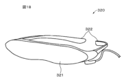
- FIG. 18 is a perspective view of an example of the appearance of a head mounted display.
- FIG. 19 is a perspective view showing an example of the appearance of the television device.
- FIG. 1 is a plan view showing an example of the configuration of a display device 10 according to the first embodiment.
- the display device 10 has a display region R1 and a peripheral region R2 provided around the display region R1.
- the display area R1 has a rectangular shape in plan view.
- a planar view means a planar view when an object is seen from a direction D P (hereinafter referred to as “perpendicular direction D P ”) perpendicular to the display surface of the display device 10 .
- a direction parallel to the long sides of the display region R1 is called a horizontal direction DH
- a direction parallel to the short sides of the display region R1 is called a vertical direction DV .
- FIG. 2 is a plan view showing an enlarged part of the display area R1 of the display device 10 according to the first embodiment.
- a plurality of sub-pixels 100R, 100G, and 100B are two-dimensionally arranged in a prescribed arrangement pattern within the display region R1.
- the peripheral region R2 is provided with a pad portion 11a, a driver (not shown) for image display, and the like.
- a flexible printed circuit (FPC) (not shown) may be connected to the pad portion 11a.
- the sub-pixel 100R can emit red light.
- the sub-pixel 100G can emit green light.
- the sub-pixel 100B can emit blue light. Red is an example of the first of the three primary colors. Green is an example of the second of the three primary colors. Blue is an example of the third primary color of the three primary colors.
- blocks marked with symbols "R", "G", and "B" represent the sub-pixel 100R, the sub-pixel 100G, and the sub-pixel 100B, respectively.
- the sub-pixels 100R, 100G, and 100B are collectively referred to as the sub-pixel 100 without any particular distinction.
- One pixel (one pixel) is composed of a combination of three sub-pixels 100R, 100G, and 100B adjacent to each other in the horizontal direction D H (row direction) of the display surface.
- the sub-pixel 100B has a linear shape extending in the vertical direction DV in plan view.
- the sub-pixels 100R and 100G are dot-shaped.
- the sub-pixels 100R, 100G, and 100B have, for example, a square shape such as a rectangular shape in plan view. In this specification, the rectangular shape includes a square shape.
- the sub-pixels 100R and 100G are alternately arranged in the vertical direction DV to form columns of sub-pixels 100R and 100G. Columns of sub-pixels 100R and 100G and linear sub-pixels 100B are alternately arranged in the horizontal direction DH .
- the pixel pitch of the sub-pixels 100R, 100G, and 100B in the horizontal direction DH is preferably 10 ⁇ m or less from the viewpoint of achieving high definition of the display device 10.
- the pixel pitch of the sub-pixels 100R and 100G in the vertical direction DP is preferably 10 ⁇ m or less from the viewpoint of achieving high definition of the display device 10.
- the display device 10 is an example of a light emitting device.
- the display device 10 is a top emission type OLED display device.
- the display device 10 may be a microdisplay.
- the display device 10 may be provided in a VR (Virtual Reality) device, an MR (Mixed Reality) device, an AR (Augmented Reality) device, an Electronic View Finder (EVF), a small projector, or the like.
- FIG. 3 is a cross-sectional view taken along line III-III in FIG.
- FIG. 4 is a cross-sectional view taken along line IV--IV of FIG.
- the display device 10 includes a circuit board 11, a plurality of light emitting elements 20, an insulating layer 12, a protective layer 13, a planarization layer 14, a color filter 15F, a filled resin layer 16, and a counter substrate 17.
- a plurality of sub-pixels 100R, 100G, and 100B are configured by combining the color filters 15F and the light-emitting elements 20.
- FIG. 1 is a cross-sectional view taken along line III-III in FIG.
- FIG. 4 is a cross-sectional view taken along line IV--IV of FIG.
- the display device 10 includes a circuit board 11, a plurality of light emitting elements 20, an insulating layer 12, a protective layer 13, a planarization layer 14, a color filter 15F, a filled resin layer 16, and a counter substrate 17.
- the surface on the top side (display surface side) of the display device 10 is referred to as a first surface
- the bottom side (opposite side to the display surface) of the display device 10 is referred to as a first surface. is called the second surface.
- the circuit board 11 is a so-called backplane and drives the plurality of light emitting elements 20 .
- the circuit board 11 is provided with a drive circuit for driving the plurality of light emitting elements 20, a power supply circuit for supplying power to the plurality of light emitting elements 20, and the like (none of which is shown).
- the substrate body of the circuit board 11 may be composed of, for example, a semiconductor that facilitates the formation of transistors or the like, or may be composed of glass or resin with low permeability to moisture and oxygen.
- the substrate body may be a semiconductor substrate, a glass substrate, a resin substrate, or the like.
- Semiconductor substrates include, for example, amorphous silicon, polycrystalline silicon, monocrystalline silicon, or the like.
- the glass substrate includes, for example, high strain point glass, soda glass, borosilicate glass, forsterite, lead glass, quartz glass, or the like.
- the resin substrate contains, for example, at least one selected from the group consisting of polymethyl methacrylate, polyvinyl alcohol, polyvinyl phenol, polyethersulfone, polyimide, polycarbonate, polyethylene terephthalate and polyethylene naphthalate.
- the light emitting element 20 is a white OLED element, and can emit white light under control of a drive circuit or the like.
- the white OLED element may be a white Micro-OLED (MOLED) element.
- MOLED white Micro-OLED
- the plurality of light emitting elements 20 are two-dimensionally arranged on the first surface of the circuit board 11 in a prescribed arrangement pattern such as a matrix.
- the multiple light emitting elements 20 include multiple first electrodes 21 , an OLED layer 22 , and a second electrode 23 in this order on the first surface of the circuit board 11 .
- the first electrode 21 is the anode. When a voltage is applied between the first electrode 21 and the second electrode 23 , holes are injected from the first electrode 21 into the OLED layer 22 .
- the first electrodes 21 are separately provided for the plurality of light emitting elements 20 .
- the plurality of first electrodes 21 are two-dimensionally arranged on the first surface of the circuit board 11 in the same arrangement pattern as the plurality of light emitting elements 20 .
- the first electrode 21 may be composed of, for example, a metal layer, or may be composed of a metal layer and a transparent conductive oxide layer.
- the transparent conductive oxide layer is the OLED layer. It is preferably provided on the 22 side.
- the metal layer also functions as a reflective layer that reflects light emitted by the OLED layer 22 .
- the metal layer is, for example, chromium (Cr), gold (Au), platinum (Pt), nickel (Ni), copper (Cu), molybdenum (Mo), titanium (Ti), tantalum (Ta), aluminum (Al). , magnesium (Mg), iron (Fe), tungsten (W) and silver (Ag).
- the metal layer may contain the at least one metal element as a constituent element of an alloy. Specific examples of alloys include aluminum alloys and silver alloys. Specific examples of aluminum alloys include AlNd and AlCu.
- a base layer may be provided adjacent to the second surface side of the metal layer.
- the underlayer is for improving the crystal orientation of the metal layer when the metal layer is formed.
- the underlayer contains, for example, at least one metal element selected from the group consisting of titanium (Ti) and tantalum (Ta).
- the underlayer may contain the at least one metal element as a constituent element of the alloy.
- the transparent conductive oxide layer contains a transparent conductive oxide.
- Transparent conductive oxides include, for example, transparent conductive oxides containing indium (hereinafter referred to as “indium-based transparent conductive oxides”) and transparent conductive oxides containing tin (hereinafter referred to as “tin-based transparent conductive oxides”). ”) and transparent conductive oxides containing zinc (hereinafter referred to as “zinc-based transparent conductive oxides”).
- Indium-based transparent conductive oxides include, for example, indium tin oxide (ITO), indium zinc oxide (IZO), indium gallium oxide (IGO), indium gallium zinc oxide (IGZO), or fluorine-doped indium oxide (IFO).
- ITO indium tin oxide
- ITO indium tin oxide
- Tin-based transparent conductive oxides include, for example, tin oxide, antimony-doped tin oxide (ATO), or fluorine-doped tin oxide (FTO).
- Zinc-based transparent conductive oxides include, for example, zinc oxide, aluminum-doped zinc oxide (AZO), boron-doped zinc oxide, or gallium-doped zinc oxide (GZO).
- the OLED layer 22 is an example of an organic layer including a light-emitting layer.
- the OLED layer 22 can emit white light by recombination of holes injected from the first electrode 21 and electrons injected from the second electrode 23 .
- the OLED layer 22 is provided between the multiple first electrodes 21 and the second electrodes 23 .
- the OLED layer 22 is provided continuously over the plurality of light emitting elements 20 within the display region R1, and is shared by the plurality of light emitting elements 20 within the display region R1.
- the OLED layer 22 may be an OLED layer with a single-layer light emitting unit, an OLED layer with two layers of light emitting units (tandem structure), or an OLED layer with a structure other than these.
- An OLED layer comprising a single layer of light-emitting units includes, for example, a hole-injecting layer, a hole-transporting layer, a red-emitting layer, a light-emitting separating layer, a blue-emitting layer, from the first electrode 21 toward the second electrode 23 . It has a configuration in which a green light-emitting layer, an electron transport layer, and an electron injection layer are laminated in this order.
- An OLED layer comprising two layers of light-emitting units is, for example, a hole-injection layer, a hole-transport layer, a blue-light-emitting layer, an electron-transport layer, a charge-generating layer, from the first electrode 21 toward the second electrode 23 . It has a structure in which a hole transport layer, a yellow light emitting layer, an electron transport layer, and an electron injection layer are laminated in this order.
- the hole injection layer is intended to increase the efficiency of hole injection into each light-emitting layer and to suppress leakage.
- the hole-transporting layer is for increasing the efficiency of hole-transporting to each light-emitting layer.
- the electron injection layer is for increasing the efficiency of electron injection into each light-emitting layer.
- the electron transport layer is for enhancing electron transport efficiency to each light-emitting layer.
- the emission separation layer is a layer for adjusting the injection of carriers into each emission layer, and the emission balance of each color is adjusted by injecting electrons and holes into each emission layer through the emission separation layer.
- the charge generation layer supplies electrons and holes, respectively, to the two light-emitting layers sandwiching the charge generation layer.
- the second electrode 23 is the cathode. When a voltage is applied between the first electrode 21 and the second electrode 23 , electrons are injected from the second electrode 23 into the OLED layer 22 .
- the second electrode 23 is a transparent electrode having transparency to visible light. In this specification, visible light refers to light in the wavelength range of 360 nm to 830 nm.
- a second electrode 23 is provided on the first surface of the OLED layer 22 .
- the second electrode 23 is provided continuously over the plurality of light emitting elements 20 within the display region R1 and is shared by the plurality of light emitting elements 20 within the display region R1.
- the second electrode 23 is made of a material with a high transmittance and a small work function, in order to increase the luminous efficiency.
- the second electrode 23 is composed of, for example, at least one layer of a metal layer and a transparent conductive oxide layer. More specifically, the second electrode 23 is composed of a single layer film of a metal layer or a transparent conductive oxide layer, or a laminated film of a metal layer and a transparent conductive oxide layer.
- the metal layer may be provided on the OLED layer 22 side, and the transparent conductive oxide layer may be provided on the OLED layer 22 side. From the viewpoint of placing a layer having a work function adjacent to the OLED layer 22, it is preferable that the metal layer is provided on the OLED layer 22 side.
- the metal layer contains, for example, at least one metal element selected from the group consisting of magnesium (Mg), aluminum (Al), silver (Ag), calcium (Ca) and sodium (Na).
- the metal layer may contain the at least one metal element as a constituent element of an alloy. Specific examples of alloys include MgAg alloys, MgAl alloys, AlLi alloys, and the like.
- the transparent conductive oxide layer includes a transparent conductive oxide. As the transparent conductive oxide, the same material as the transparent conductive oxide of the first electrode 21 can be exemplified.
- the insulating layer 12 provides insulation between adjacent first electrodes 21 .
- the insulating layer 12 is provided on a portion of the first surface of the circuit board 11 between the separated first electrodes 21 .
- the insulating layer 12 has a plurality of openings 12a.
- a plurality of openings 12a are provided corresponding to the respective light emitting elements 20, respectively. More specifically, each of the plurality of openings 12a is provided on the first surface (surface on the OLED layer 22 side) of each first electrode 21 .
- the first electrode 21 and the OLED layer 22 are in contact with each other through the opening 12a.
- the insulating layer 12 may be an organic insulating layer, an inorganic insulating layer, or a laminate of these layers.
- the organic insulating layer contains, for example, at least one selected from the group consisting of polyimide-based resins, acrylic-based resins, novolak-based resins, and the like.
- the inorganic insulating layer contains, for example, at least one selected from the group consisting of silicon oxide (SiO x ), silicon nitride (SiN x ), silicon oxynitride (SiO x N y ), and the like.
- the protective layer 13 has transparency to visible light.
- the protective layer 13 is provided on the first surface of the second electrode 23 and covers the plurality of light emitting elements 20 .
- the protective layer 13 shields the light-emitting element 20 from the outside air and suppresses moisture from entering the light-emitting element 20 from the external environment.
- the protective layer 13 may have a function of suppressing oxidation of this metal layer.
- the protective layer 13 contains, for example, a low hygroscopic inorganic material or polymer resin.
- the protective layer 13 may have a single layer structure or a multilayer structure. When increasing the thickness of the protective layer 13, it is preferable to have a multilayer structure. This is for alleviating the internal stress in the protective layer 13 .
- the inorganic material is, for example, selected from the group consisting of silicon oxide (SiO x ), silicon nitride (SiN x ), silicon oxynitride (SiO x N y ), titanium oxide (TiO x ) and aluminum oxide (AlO x ).
- Polymer resins include, for example, at least one selected from the group consisting of thermosetting resins, ultraviolet-curable resins, and the like.
- the polymer resin includes at least one selected from the group consisting of acrylic resins, polyimide resins, novolac resins, epoxy resins, norbornene resins, and the like.
- the planarizing layer 14 is provided on the first surface of the protective layer 13 and planarizes the unevenness of the first surface of the protective layer 13 .
- the planarization layer 14 contains, for example, an inorganic material or a polymeric resin. Examples of the inorganic material include materials similar to those of the protective layer 13 .
- the polymer resin the same material as that of the protective layer 13 can be exemplified.
- the color filter 15F is an on-chip color filter (OCCF).
- OCCF on-chip color filter
- a color filter 15 ⁇ /b>F is provided above the plurality of light emitting elements 20 . More specifically, the color filter 15F is provided on the first surface of the planarization layer 14.
- the color filter 15F includes, for example, a plurality of red filter portions 15R, a plurality of green filter portions 15G, and a plurality of blue filter portions 15B.
- the red filter section 15R, the green filter section 15G, and the blue filter section 15B are collectively referred to as the filter section 15 without particular distinction.
- the plurality of filter portions 15 are two-dimensionally arranged in the in-plane direction.
- the in-plane direction means the in-plane direction on the first surface of the circuit board 11 .
- Each filter section 15 is provided above the light emitting element 20 .
- a sub-pixel 100R is composed of a red filter portion 15R and a light emitting element 20.
- a sub-pixel 100G is composed of a green filter portion 15G and a light emitting element 20.
- the sub-pixel 100B is composed of a blue filter portion 15B and a light emitting element 20. As shown in FIG.
- the red filter portion 15R transmits red light out of the white light emitted from the light emitting element 20, but absorbs light other than red light.
- the green filter portion 15G transmits green light out of the white light emitted from the light emitting element 20, but absorbs light other than green light.
- the blue filter portion 15B transmits blue light out of the white light emitted from the light emitting element 20, but absorbs light other than blue light.
- the blue filter portion 15B has a linear shape extending in the vertical direction DV in plan view.
- the red filter portion 15R and the green filter portion 15G have a dot shape in plan view, similarly to the sub-pixel 100R and the sub-pixel 100G.
- the red filter portion 15R and the green filter portion 15G have, for example, a square shape such as a rectangular shape in plan view.
- At least one color filter portion 15 among the blue filter portion 15B, the green filter portion 15G and the red filter portion 15R includes a transparent resin 150 at the bottom of the filter portion 15 .
- one of the blue filter portion 15B, the green filter portion 15G, and the red filter portion 15R may include the transparent resin 150 at the bottom of the filter portion 15, or the blue filter portion 15B may include the transparent resin 150.
- the green filter portion 15G and the red filter portion 15R the two color filter portions 15 may include the transparent resin 150 at the bottom portion of the filter portion 15, or the blue filter portion 15B, the green filter portion 15G and the red filter portion 15R. may include transparent resin 150 at the bottom of the filter portion 15 .
- the filter portion 15 may include the transparent resin 150 in a portion of the bottom portion of the filter portion 15 , or may include the transparent resin 150 in substantially the entire bottom portion of the filter portion 15 .
- the blue filter portion 15B includes a transparent resin 150 at the bottom of the blue filter portion 15B.
- the transparent resin 150 may extend over a plurality of light emitting elements 20 in the vertical direction DV , or may be divided between adjacent light emitting elements 20 .
- the transparent resin 150 bonds the bottom portion of the color filter 15F and the planarization layer 14 together, and can suppress the peeling of the color filter 15F from the planarization layer 14 .
- the transparent resin 150 preferably has transparency to visible light. Since the transparent resin 150 has transparency to visible light, it is possible to suppress absorption of the white light emitted from the light emitting element 20 by the transparent resin 150 . Therefore, a decrease in brightness of the display device 10 can be suppressed.
- the transparent resin 150 may have a layered shape. That is, the transparent resin 150 may form a transparent resin layer on the bottom of the filter section 15 .
- the transparent resin 150 is not limited to a layered shape, and may be granular or irregularly shaped.
- the filter part 15 may contain one or more granular transparent resins 150 at the bottom, or may contain one or more amorphous transparent resins 150 .
- the filter part 15 may contain at least one selected from the group consisting of the layered transparent resin 150, the granular transparent resin 150, and the amorphous transparent resin 150 in the bottom part.
- the transparent resin 150 preferably contains a thermosetting resin.
- the thermosetting resin includes, for example, thermosetting organic resin such as epoxy resin.
- the transparent resin 150 and the filled resin layer 16 preferably contain materials with the same components. Since the transparent resin 150 and the filling resin layer 16 contain materials of the same component, the transparent resin 150 is allowed to permeate the color filter 15F and harden to form the filling resin layer 16. can exist in That is, the transparent resin 150 allows the color filter 15F and the flattening layer 14 to be attached together.
- thermosetting resin includes, for example, thermosetting organic resin such as epoxy resin.
- thermosetting resin for forming the filling resin layer 16 is permeated into the color filter 15F and cured in the baking process described later, thereby making the resin transparent.
- a resin 150 can be present at the bottom of the color filter 15F. That is, the transparent resin 150 allows the color filter 15F and the flattening layer 14 to be attached together.
- the peripheral edge portions of adjacent filter portions 15 may overlap each other. It is preferable that the filter part 15 located on the upper side in the overlap of the peripheral parts contains the transparent resin 150 at the bottom.
- the filter portion 15 located on the upper side in the overlap of the peripheral edge portions is more likely to be peeled off in the below-described baking process than the filter portion 15 located on the lower side in the overlap of the peripheral edge portions. Therefore, from the viewpoint of suppressing peeling of the color filter 15F by the transparent resin 150, it is preferable that the filter section 15 located on the upper side in the overlap of the peripheral edge contains the transparent resin 150 at the bottom.
- the peripheral portion of the filter portion 15 refers to a region having a predetermined width inward from the peripheral edge of the filter portion 15 .
- the peripheral portion of the blue filter portion 15B and the peripheral portion of the green filter portion 15G may overlap in the horizontal direction DH .
- the peripheral portion of the blue filter portion 15B may be positioned above the peripheral portion of the green filter portion 15G in the horizontal direction DH .
- the peripheral portion of the blue filter portion 15B contains the transparent resin 150 at the bottom.
- the periphery of the blue filter portion 15B and the periphery of the red filter portion 15R may overlap in the horizontal direction DH .
- the peripheral portion of the blue filter portion 15B may be positioned above the peripheral portion of the red filter portion 15R in the horizontal direction DH .
- the peripheral portion of the blue filter portion 15B contains the transparent resin 150 at the bottom.
- the periphery of the red filter portion 15R and the periphery of the green filter portion 15G may overlap in the vertical direction DV .
- the peripheral portion of the red filter portion 15R may be positioned above the peripheral portion of the green filter portion 15G in the vertical direction DV .
- the peripheral portion of the red filter portion 15R contains the transparent resin 150 at the bottom.
- the width W of the overlapping edge portions of the adjacent filter portions 15 is 0.1 ⁇ m or more and 0.5 ⁇ m or less. However, the overlapping width W of the filter portions 15 may exceed 0.5 ⁇ m. If the width of overlap between the peripheral edges differs depending on the position, the maximum value of the widths of overlap between the peripheral edges is defined as the width W of the overlap between the peripheral edges.
- the red filter portion 15R contains, for example, a red coloring agent and an ultraviolet curable resin.
- the red colorant includes, for example, at least one selected from the group consisting of red dyes and red pigments.
- the green filter section 15G contains, for example, a green coloring agent and an ultraviolet curable resin. Green coloring agents include, for example, at least one selected from the group consisting of green dyes and green pigments.
- the blue filter section 15B contains, for example, a blue colorant and an ultraviolet curable resin. Blue colorants include, for example, at least one selected from the group consisting of blue dyes and blue pigments.
- the filling resin layer 16 is provided between the color filter 15F and the opposing substrate 17. As shown in FIG.
- the filling resin layer 16 functions as an adhesive layer that bonds the color filter 15F and the counter substrate 17 together.
- the filled resin layer 16 contains, for example, a thermosetting resin.
- the thermosetting resin is preferably a transparent resin.
- the transparent resin preferably contains the same material as the transparent resin 150 contained in the bottom of the filter section 15 .
- Thermosetting resins include, for example, thermosetting organic resins such as epoxy resins.
- the filling resin layer 16 may further contain an ultraviolet curable resin.
- the counter substrate 17 seals the light emitting element 20, the color filter 15F, and the like.
- the counter substrate 17 has transparency to visible light, for example.
- the counter substrate 17 is provided on the first surface of the filling resin layer 16 and faces the circuit board 11 .
- the opposing substrate 17 is, for example, a glass substrate.
- Step of forming first electrode 21 First, a metal layer and a metal oxide layer are sequentially formed on the first surface of the circuit board 11 by, for example, a sputtering method, and then the metal layer and the metal oxide layer are patterned by, for example, a photolithography technique and an etching technique. . Thereby, a plurality of first electrodes 21 are formed on the first surface of the circuit board 11 .
- the insulating layer 12 is formed on the first surface of the circuit board 11 so as to cover the plurality of first electrodes 21 by, for example, a CVD (Chemical Vapor Deposition) method.
- openings 12a are formed in portions of the insulating layer 12 located on the first surfaces of the first electrodes 21 by photolithography and dry etching, for example.
- a hole transport layer, a red light emitting layer, a light emitting separation layer, a blue light emitting layer, a green light emitting layer, an electron transport layer, and an electron injection layer are formed on the first surface of the plurality of first electrodes 21 by vapor deposition, for example. and on the first surface of the insulating layer 12 in this order to form the OLED layer 22 .
- a second electrode 23 is formed on the first surface of the OLED layer 22 by vapor deposition or sputtering, for example. Thereby, a plurality of light emitting elements 20 are formed on the first surface of the circuit board 11 .
- the protective layer 13 is formed on the first surface of the second electrode 23 by, for example, CVD or vapor deposition.
- planarization layer 14 is formed on the first surface of the second electrode 23 by, for example, CVD or vapor deposition.
- a coloring composition for forming a green filter portion is applied onto the first surface of the planarizing layer 14, irradiated with ultraviolet rays through a photomask for pattern exposure, and then developed to form a green filter portion 15G.
- a coloring composition for forming a red filter portion is applied onto the first surface of the planarizing layer 14, and patterned exposure is performed by irradiating ultraviolet rays through a photomask, followed by development to form a red filter portion 15R.
- a coloring composition for forming a blue filter portion is applied onto the first surface of the flattening layer 14, irradiated with ultraviolet rays through a photomask for pattern exposure, and then developed to form a blue filter portion 15B. to form Thereby, a color filter 15F is formed on the first surface of the planarization layer 14, as shown in FIG.
- Step of Overlapping Counter Substrate 17 Next, after covering the color filter 15F with the filling resin layer 16 using, for example, the ODF (One Drop Fill) method, as shown in FIG.
- thermosetting resin contained in the filled resin layer 16 begins to permeate the color filters 15F.
- the thermosetting resin is preferably a transparent resin. Since the blue filter portion 15B is positioned above the green filter portion 15G in the overlapping of the peripheral portions in the horizontal direction DH , when the baking process is started, as shown in FIG. On the other hand, stress (see the arrow in FIG. 8) is likely to be applied in a direction that lifts the blue filter portion 15B. Further, although not shown, the blue filter portion 15B is positioned above the red filter portion 15R in the overlapping of the peripheral portions in the horizontal direction DH . Stress is likely to be applied in a direction that lifts the portion 15B.
- a cavity 151 begins to form between the blue filter section 15B and the underlying planarization layer 14 .
- the cavities 151 are filled with a thermosetting resin that permeates the color filters 15F.
- the mold resin is cured.
- the color filter 15F and the counter substrate 17 are bonded via the filling resin layer 16 to seal the display device 10, and a transparent resin layer 150 or the like is formed on the bottom of the blue filter portion 15B.
- the phenomena shown in FIGS. 7 to 9 were explained separately for easy understanding, but the phenomena shown in FIGS. 7 to 9 may proceed simultaneously.
- the display device 10 shown in FIGS. 1 to 3 is obtained.
- the OCCF is formed above the heat-sensitive light-emitting layer. Therefore, there is a process limitation that the OCCF must be formed by a low temperature process. Therefore, in the conventional display device, sufficient heat treatment cannot be performed in the OCCF formation process, and the adhesion between the OCCF and its underlying layer (for example, a planarization layer or a protective layer) is reduced, resulting in the problem that the OCCF is easily peeled off. .
- display characteristics eg, uniformity, chromaticity, viewing angle, display surface roughness, etc.
- reliability for example, image defects due to progression of peeling of OCCF may be lowered.
- At least one color filter portion 15 among the red filter portion 15R, the green filter portion 15G and the blue filter portion 15B includes a transparent resin 150 at the bottom.
- the transparent resin 150 can bond the color filter 15F and the flattening layer 14 thereunder, thereby suppressing peeling of the color filter 15F. Therefore, deterioration of display characteristics can be suppressed.
- the transparent resin 150 since the transparent resin 150 has transparency to visible light, it is possible to suppress a decrease in brightness of the display device 10 .
- the transparent resin 150 on the bottom of the filter section 15 is baked, and the thermosetting resin for forming the filling resin layer 16 permeates the color filter 15F. , filling the cavity 151 formed at the bottom of the filter part 15, and curing. Therefore, it is possible to form a layer of the transparent resin 150 or the like on the part that is easily peeled off due to the formation of the cavity 151 .
- a layer of the transparent resin 150 or the like can be formed on the bottom portion of the filter section 15 in the baking process (sealing process) for thermally curing the filling resin layer 16 . can. Therefore, peeling of the color filter 15F can be suppressed without increasing the manufacturing process.
- the OCCF must be formed by a low-temperature process. Therefore, in conventional display devices, the adhesion between the OCCF and its underlying layer (for example, a planarizing layer or a protective layer) is poor. There is a problem that the OCCF is easily peeled off.
- As methods for suppressing peeling of the OCCF (1) a method of increasing the installation area between the OCCF and the base layer, and (2) a method of increasing the overlapping of the peripheral edge portions of the adjacent filter portions (overlap) are conceivable.
- the width W of the overlapping filter portions is preferably 0.1 ⁇ m or more and 0.5 ⁇ m or less.
- the OCCF is easily peeled off due to the stress itself of the filter portion due to the overlap.
- the overlapping width W of the filter portions 15 is 0.00. Even when the thickness exceeds 5 ⁇ m, peeling of the color filter 15F can be suppressed.
- FIG. 10 is a plan view showing an enlarged part of the display region R1 of the display device 10A according to the second embodiment.
- 11 is a cross-sectional view taken along line XI-XI of FIG. 10.
- FIG. 12 is a cross-sectional view taken along line XII--XII in FIG. 10.
- FIG. 10A instead of forming a plurality of sub-pixels 100R, 100G, and 100B (see FIGS. 2 to 4) by combining the color filters 15F and the light emitting elements 20, the color filters 15F1 and the light emitting elements 20 are combined.
- the display device 10 differs from the display device 10 according to the first embodiment in that a plurality of sub-pixels 100R, 100G, 100B1, and 100IR are configured by .
- symbol is attached
- blocks marked with symbols "R”, “G”, “B”, and "IR” represent sub-pixel 100R, sub-pixel 100G, sub-pixel 100B1, and sub-pixel 100IR, respectively.
- the sub-pixel 100B1 can emit blue light.
- the sub-pixel 100B1 has a dot shape.
- the sub-pixel 100IR has, for example, a quadrangular shape such as a rectangular shape in plan view.
- the sub-pixel 100IR can emit infrared rays.
- the sub-pixel 100IR has a dot shape.
- the sub-pixel 100IR has, for example, a quadrangular shape such as a rectangular shape in plan view.
- the sub-pixels 100B1 and 100IR are alternately arranged in the vertical direction DV to form columns of sub-pixels 100B1 and 100IR.
- the sub-pixels 100R and 100G are alternately arranged in the vertical direction DV to form columns of sub-pixels 100R and 100G.
- Columns composed of sub-pixels 100B1 and 100IR and columns composed of sub-pixels 100R and 100G are alternately arranged in the horizontal direction DH .
- the sub-pixels 100B1 and 100R are alternately arranged in the horizontal direction DH to form a row of sub-pixels 100B1 and 100R.
- the sub-pixels 100IR and 100G are alternately arranged in the horizontal direction DH to form a row of the sub-pixels 100IR and 100G.
- Rows of sub-pixels 100B1 and 100R and rows of sub-pixels 100IR and 100G are alternately arranged in the vertical direction DV .
- the color filter 15F1 includes, for example, a plurality of red filter portions 15R, a plurality of green filter portions 15G, a plurality of blue filter portions 15B1, and a plurality of infrared transmission filter portions 15IR.
- the red filter section 15R, the green filter section 15G, the blue filter section 15B1, and the infrared transmission filter section 15IR are collectively referred to as the filter section 15 without particular distinction.
- the plurality of filter portions 15 are two-dimensionally arranged in the in-plane direction. Each filter section 15 is provided above the light emitting element 20 .
- a sub-pixel 100 B 1 is composed of a blue filter portion 15 B 1 and a light emitting element 20 .
- a sub-pixel 100IR is composed of an infrared transmission filter portion 15IR and a light-emitting element 20 .
- the white light emitted from the light emitting element 20 includes infrared light (infrared (IR)).
- the blue filter section 15B1 transmits blue light, but absorbs light other than blue light.
- the infrared transmission filter portion 15IR transmits infrared light among the white light emitted from the light emitting element 20, but absorbs light other than infrared light.
- the blue filter portion 15B1 and the infrared transmission filter portion 15IR have a dot shape in plan view, like the sub-pixels 100B1 and 100IR.
- the blue filter portion 15B1 and the infrared transmission filter portion 15IR have, for example, a square shape such as a rectangular shape in plan view.
- At least one of the blue filter portion 15B1, the green filter portion 15G, the red filter portion 15R, and the infrared transmission filter portion 15IR includes a transparent resin 150 at the bottom of the filter portion 15.
- one of the blue filter portion 15B1, the green filter portion 15G, the red filter portion 15R, and the infrared transmission filter portion 15IR includes the transparent resin 150 at the bottom of the filter portion 15.
- two types of filter portions 15 out of the blue filter portion 15B1, the green filter portion 15G, the red filter portion 15R, and the infrared transmission filter portion 15IR may include the transparent resin 150 at the bottom of the filter portion 15,
- Three types of filter portions 15 out of the blue filter portion 15B1, the green filter portion 15G, the red filter portion 15R, and the infrared transmission filter portion 15IR may include the transparent resin 150 at the bottom of the filter portion 15, or the blue filter portion All of 15B1, green filter section 15G, red filter section 15R and infrared transmission filter section 15IR may include transparent resin 150 at the bottom of filter section 15 concerned.
- the infrared transmission filter portion 15IR includes the transparent resin 150 at the bottom of the infrared transmission filter portion 15IR
- the blue filter portion 15B1 includes the transparent resin 150 at the bottom of the blue filter portion 15B1.
- An example including is shown.
- the peripheral edge portions of adjacent filter portions 15 may overlap each other. It is preferable that the filter part 15 located on the upper side in the overlap of the peripheral parts contains the transparent resin 150 at the bottom.
- the peripheral portion of the infrared transmission filter portion 15IR and the peripheral portion of the green filter portion 15G may overlap in the horizontal direction DH .
- the peripheral portion of the infrared transmission filter portion 15IR may be positioned above the peripheral portion of the green filter portion 15G in the horizontal direction DH .
- the peripheral portion of the infrared transmission filter portion 15IR includes the transparent resin 150 at the bottom.
- the peripheral portion of the green filter portion 15G may be positioned above the peripheral portion of the infrared transmission filter portion 15IR in the horizontal direction DH .
- the peripheral portion of the green filter portion 15G includes the transparent resin 150 at the bottom.
- the peripheral portion of the blue filter portion 15B1 and the peripheral portion of the red filter portion 15R may overlap in the horizontal direction DH .
- the peripheral portion of the blue filter portion 15B1 may be positioned above the peripheral portion of the red filter portion 15R in the horizontal direction DH .
- the peripheral portion of the blue filter portion 15B1 includes the transparent resin 150 at the bottom.
- the periphery of the red filter portion 15R and the periphery of the green filter portion 15G may overlap in the vertical direction DV .
- the peripheral portion of the red filter portion 15R may be positioned above the peripheral portion of the green filter portion 15G in the vertical direction DV .
- the peripheral portion of the red filter portion 15R contains the transparent resin 150 at the bottom.
- the peripheral portion of the blue filter portion 15B1 and the peripheral portion of the infrared transmission filter portion 15IR may overlap in the vertical direction DV .
- the peripheral portion of the blue filter portion 15B1 may be positioned above the peripheral portion of the infrared transmission filter portion 15IR in the vertical direction DV .
- the peripheral portion of the blue filter portion 15B1 includes the transparent resin 150 at the bottom.
- the peripheral portion of the infrared transmission filter portion 15IR may be positioned above the peripheral portion of the blue filter portion 15B1 in the vertical direction DV .
- the peripheral portion of the infrared transmission filter portion 15IR includes the transparent resin 150 at the bottom.
- the blue filter section 15B1 contains, for example, a blue colorant and an ultraviolet curable resin.
- Blue colorants include, for example, at least one selected from the group consisting of blue dyes and blue pigments.
- the infrared transmission filter portion 15IR includes, for example, an infrared transmission black color material and an ultraviolet curable resin.
- At least one of the red filter portion 15R, the green filter portion 15G, the blue filter portion 15B1, and the infrared transmission filter portion 15IR has a transparent resin 150 at the bottom.
- the transparent resin 150 can bond the color filter 15F and the flattening layer 14 therebelow, thereby preventing the color filter 15F1 from peeling off.
- the function of the display device 10A can be improved by including the sub-pixel 100IR in addition to the sub-pixels 100R, 100G, and 100B1 each having three primary colors. Therefore, it is possible to improve the function of the display device 10A while suppressing peeling of the color filter 15F1.
- FIG. 13 is a plan view showing an enlarged part of the display region R1 of the display device 10B according to the third embodiment.
- 14 is a cross-sectional view taken along line XIV--XIV in FIG. 13.
- FIG. 10B instead of forming a plurality of sub-pixels 100R, 100G, 100B1, and 100IR (see FIGS. 10 to 12) by combining the color filter 15F1 and the light emitting element 20, the display device 10B includes the color filter 15F2 and the light emitting element 20. are different from the display device 10A according to the second embodiment in that a plurality of sub-pixels 100R, 100G, 100B1, and 100W are configured by combining .
- the sub-pixel 100W can emit white light.
- the sub-pixel 100W has a dot shape.
- the sub-pixel 100W has, for example, a square shape such as a rectangular shape in plan view.
- the sub-pixels 100B1 and 100W are alternately arranged in the vertical direction DV to form columns of sub-pixels 100B1 and 100W.
- the sub-pixels 100R and 100G are alternately arranged in the vertical direction DV to form columns of sub-pixels 100R and 100G.
- Columns composed of sub-pixels 100B1 and 100W and columns composed of sub-pixels 100R and 100G are alternately arranged in the horizontal direction DH .
- the sub-pixels 100B1 and 100R are alternately arranged in the horizontal direction DH to form a row of sub-pixels 100B1 and 100R.
- the sub-pixels 100W and 100G are alternately arranged in the horizontal direction DH to form a row of sub-pixels 100W and 100G. Rows of sub-pixels 100B1 and 100R and rows of sub-pixels 100W and 100G are alternately arranged in the vertical direction DV .
- the color filter 15F2 includes, for example, a plurality of red filter portions 15R, a plurality of green filter portions 15G, a plurality of blue filter portions 15B1, and a plurality of light transmission portions 15W.
- the red filter section 15R, the green filter section 15G, and the blue filter section 15B1 are collectively referred to as the filter section 15 without particular distinction.
- the plurality of filter portions 15 and the plurality of light transmission portions 15W are two-dimensionally arranged in the in-plane direction.
- Each filter section 15 is provided above the light emitting element 20 .
- Each light transmission part 15W is also provided above the light emitting element 20 .
- a sub-pixel 100W is composed of a light transmitting portion 15W and a light emitting element 20. As shown in FIG.
- the light transmitting portion 15W can transmit white light emitted from the light emitting element 20 .
- the light transmitting portion 15W is, for example, an opening penetrating in the perpendicular direction DP .
- the light transmission portion 15W has a dot shape in plan view, similar to the sub-pixels 100R, 100G, and 100B1.
- the light transmitting portion 15W has, for example, a quadrangular shape such as a rectangular shape in plan view.
- At least one color filter portion 15 among the red filter portion 15R, the green filter portion 15G and the blue filter portion 15B1 includes a transparent resin 150 at the bottom of the filter portion 15 concerned.
- one of the red filter portion 15R, the green filter portion 15G, and the blue filter portion 15B1 may include the transparent resin 150 at the bottom of the filter portion 15, or the red filter portion 15R may , the green filter portion 15G and the blue filter portion 15B1, the two color filter portions 15 may include the transparent resin 150 at the bottom portion of the filter portion 15, or the red filter portion 15R, the green filter portion 15G and the blue filter portion 15B1. may include transparent resin 150 at the bottom of the filter portion 15 .
- At least one of the red filter portion 15R, the green filter portion 15G, and the blue filter portion 15B1 includes a transparent resin 150 at the bottom.
- the color filter 15F2 and the underlying planarization layer 14 can be bonded together by the transparent resin 150, so that peeling of the color filter 15F2 can be suppressed.
- one pixel includes the sub-pixel 100W in addition to the sub-pixels 100R, 100G, and 100B1 of the three primary colors, so that the luminance of the display device 10B can be improved. Therefore, it is possible to improve the luminance of the display device 10B while suppressing peeling of the color filter 15F2.
- FIG. 15 is a plan view showing an enlarged part of the display region R1 of the display device 10C according to Modification 1.
- the display device 10C differs from the display device 10 according to the second embodiment in that one pixel is formed by combining four sub-pixels 100R, 100G, 100B1, and 100B1.
- the sub-pixels 100G and 100B1 are alternately arranged in the vertical direction DV to form columns of sub-pixels 100G and 100B1.
- the sub-pixels 100B1 and 100R are alternately arranged in the vertical direction DV to form columns of sub-pixels 100B1 and 100R.
- Columns composed of the sub-pixels 100G and 100B1 and columns composed of the sub-pixels 100B1 and 100R are alternately arranged in the horizontal direction DH .
- the sub-pixels 100G and 100B1 are alternately arranged in the horizontal direction DH to form a row of sub-pixels 100G and 100B1.
- the sub-pixels 100B1 and 100R are alternately arranged in the horizontal direction DH to form a row of sub-pixels 100B1 and 100R. Rows of sub-pixels 100G and 100B and rows of sub-pixels 100B1 and 100R are alternately arranged in the vertical direction DV .
- Modification 2 In the first embodiment, the example in which the sub-pixels 100R and 100G have a square shape in plan view and the sub-pixel 100B has a linear shape in plan view has been described. is not limited to this example.
- FIG. 16 is a plan view showing an enlarged part of the display region R1 of the display device 10D according to Modification 2.
- FIG. The display device 10D differs from the first embodiment in that sub-pixels 100R, 100G, and 100B have a hexagonal shape in plan view. Although illustration is omitted, the sub-pixels 100R, 100G, and 100B may have a circular shape or an elliptical shape in plan view, or may have a polygonal shape other than a square shape and a hexagonal shape in plan view. good.
- one pixel is composed of three sub-pixels 100 or four sub-pixels 100
- the configuration of one pixel is not limited to this example.
- one pixel may be composed of two sub-pixels 100 or five or more sub-pixels 100 .
- the color filter may include two color filter portions or five or more color filter portions.
- the color filter 15F2 includes the light transmission portion 15W and the light transmission portion 15W is an opening has been described, but the light transmission portion 15W may be a transparent filter portion.
- the transparent filter section has transparency to visible light.
- the transparent filter section contains, for example, an ultraviolet curable resin.
- the light transmitting portion 15W is a transparent filter portion
- at least one of the red filter portion 15R, the green filter portion 15G, the blue filter portion 15B1, and the transparent filter portion 15 may include a transparent resin 150 at the bottom.
- the color filter may be used for purposes such as antireflection.
- the color filter may be a monochromatic filter, may have two or more color filter portions, or may be the color filter 15F in one embodiment.
- the color filter 15F includes a plurality of red filter portions 15R, a plurality of green filter portions 15G, and a plurality of blue filter portions 15B has been described. It is not limited.
- the color filter 15F further includes at least one of a plurality of cyan filter sections and a plurality of magenta filter sections in addition to the plurality of red filter sections 15R, the plurality of green filter sections 15G, and the plurality of blue filter sections 15B.
- the cyan color filter section and the magenta color filter section are complementary color filters for adjusting colored light in the sub-pixels 100R, 100G, and 100B.
- the color filter 15F1 may further include at least one of a plurality of cyan color filter portions and a plurality of magenta color filter portions.
- the color filter 15F2 may further include at least one of a plurality of cyan color filter portions and a plurality of magenta color filter portions.
- the cavity 151 may be formed depending on the combination of 15F and its lower layer material, the material of the filling resin layer 16, or the process conditions at the time of sealing with the opposing substrate 17, or the like. Cavities 151 may be formed by a combination of two or more of the above conditions.
- the present disclosure can also employ the following configuration.
- a plurality of light emitting elements arranged two-dimensionally; a filter provided above the plurality of light emitting elements and including a plurality of color filter portions, The light-emitting device, wherein at least one color filter portion of the plurality of color filter portions includes a transparent resin at the bottom.
- the transparent resin includes a thermosetting resin.
- the transparent resin includes an epoxy-based resin.
- the light-emitting device according to any one of (1) to (8), wherein the plurality of color filter sections includes a plurality of red filter sections, a plurality of green filter sections, and a plurality of blue filter sections.
- the filter further includes a plurality of infrared transmission filter sections.
- the plurality of light emitting elements are capable of emitting white light
- the filter further includes a plurality of light transmission parts, The light-emitting device according to (9), wherein the light-transmitting portion can transmit the white light.
- the light-emitting device according to any one of (1) to (11), wherein the transparent resin is present on substantially the entire bottom portion.
- the light-emitting device according to any one of (1) to (13), wherein the transparent resin is layered.
- the light-emitting device according to any one of (1) to (14), wherein the transparent resin is granular.
- a plurality of light emitting elements arranged two-dimensionally; a filter provided above the plurality of light emitting elements, The light-emitting device, wherein the filter includes a filter portion containing a transparent resin at the bottom.
- An electronic device comprising the light emitting device according to any one of (1) to (16).
- the display devices 10, 10A, 10B, 10C, and 10D (hereinafter referred to as "display devices 10, etc.") according to the first to third embodiments and modifications thereof can be used in various electronic devices.
- the display device 10 or the like is particularly suitable for video cameras, electronic viewfinders of single-lens reflex cameras, or head-mounted displays that require high resolution and are used in close proximity to the eyes.
- FIG. 1 This digital still camera 310 is of an interchangeable single-lens reflex type, and has an interchangeable photographing lens unit (interchangeable lens) 312 in approximately the center of the front of a camera main body (camera body) 311, and on the left side of the front. It has a grip portion 313 for a photographer to hold.
- interchangeable photographing lens unit interchangeable lens
- a monitor 314 is provided at a position shifted to the left from the center of the back surface of the camera body 311 .
- An electronic viewfinder (eyepiece window) 315 is provided above the monitor 314 . By looking through the electronic viewfinder 315, the photographer can view the optical image of the subject guided from the photographing lens unit 312 and determine the composition.
- the electronic viewfinder 315 includes any one of the display device 10 and the like.
- FIG. 18 shows an example of the appearance of the head mounted display 320.
- the head-mounted display 320 has, for example, ear hooks 322 on both sides of an eyeglass-shaped display 321 to be worn on the user's head.
- the display unit 321 includes any one of the display device 10 and the like.
- FIG. 19 shows an example of the appearance of the television device 330.
- the television apparatus 330 has, for example, an image display screen portion 331 including a front panel 332 and a filter glass 333, and the image display screen portion 331 includes any one of the display device 10 and the like.
Landscapes
- Physics & Mathematics (AREA)
- Optics & Photonics (AREA)
- General Physics & Mathematics (AREA)
- Electroluminescent Light Sources (AREA)
- Led Device Packages (AREA)
Priority Applications (3)
| Application Number | Priority Date | Filing Date | Title |
|---|---|---|---|
| CN202280080342.1A CN118355299A (zh) | 2021-12-10 | 2022-11-15 | 发光装置和电子设备 |
| US18/702,913 US20260047302A1 (en) | 2021-12-10 | 2022-11-15 | Light emitting device and electronic apparatus |
| JP2023566193A JPWO2023106050A1 (https=) | 2021-12-10 | 2022-11-15 |
Applications Claiming Priority (2)
| Application Number | Priority Date | Filing Date | Title |
|---|---|---|---|
| JP2021-201231 | 2021-12-10 | ||
| JP2021201231 | 2021-12-10 |
Publications (1)
| Publication Number | Publication Date |
|---|---|
| WO2023106050A1 true WO2023106050A1 (ja) | 2023-06-15 |
Family
ID=86730369
Family Applications (1)
| Application Number | Title | Priority Date | Filing Date |
|---|---|---|---|
| PCT/JP2022/042416 Ceased WO2023106050A1 (ja) | 2021-12-10 | 2022-11-15 | 発光装置および電子機器 |
Country Status (5)
| Country | Link |
|---|---|
| US (1) | US20260047302A1 (https=) |
| JP (1) | JPWO2023106050A1 (https=) |
| CN (1) | CN118355299A (https=) |
| TW (1) | TW202347760A (https=) |
| WO (1) | WO2023106050A1 (https=) |
Citations (4)
| Publication number | Priority date | Publication date | Assignee | Title |
|---|---|---|---|---|
| JP2001194657A (ja) * | 2000-01-11 | 2001-07-19 | Seiko Epson Corp | 液晶表示装置及びその製造方法並びに電子機器 |
| JP2012038677A (ja) * | 2010-08-11 | 2012-02-23 | Seiko Epson Corp | 有機el装置、有機el装置の製造方法、及び電子機器 |
| JP2017181831A (ja) * | 2016-03-31 | 2017-10-05 | ソニー株式会社 | 表示装置及び電子機器 |
| WO2020111101A1 (ja) * | 2018-11-30 | 2020-06-04 | ソニー株式会社 | 表示装置 |
-
2022
- 2022-11-15 CN CN202280080342.1A patent/CN118355299A/zh active Pending
- 2022-11-15 US US18/702,913 patent/US20260047302A1/en active Pending
- 2022-11-15 WO PCT/JP2022/042416 patent/WO2023106050A1/ja not_active Ceased
- 2022-11-15 JP JP2023566193A patent/JPWO2023106050A1/ja active Pending
- 2022-11-21 TW TW111144319A patent/TW202347760A/zh unknown
Patent Citations (4)
| Publication number | Priority date | Publication date | Assignee | Title |
|---|---|---|---|---|
| JP2001194657A (ja) * | 2000-01-11 | 2001-07-19 | Seiko Epson Corp | 液晶表示装置及びその製造方法並びに電子機器 |
| JP2012038677A (ja) * | 2010-08-11 | 2012-02-23 | Seiko Epson Corp | 有機el装置、有機el装置の製造方法、及び電子機器 |
| JP2017181831A (ja) * | 2016-03-31 | 2017-10-05 | ソニー株式会社 | 表示装置及び電子機器 |
| WO2020111101A1 (ja) * | 2018-11-30 | 2020-06-04 | ソニー株式会社 | 表示装置 |
Also Published As
| Publication number | Publication date |
|---|---|
| TW202347760A (zh) | 2023-12-01 |
| US20260047302A1 (en) | 2026-02-12 |
| CN118355299A (zh) | 2024-07-16 |
| JPWO2023106050A1 (https=) | 2023-06-15 |
Similar Documents
| Publication | Publication Date | Title |
|---|---|---|
| TWI651703B (zh) | 有機發光顯示裝置 | |
| TWI596760B (zh) | 有機el裝置、有機el裝置之製造方法、及具備有機el裝置之電子機器 | |
| KR102431372B1 (ko) | 컬러필터 어레이 기판 및 이를 포함하는 유기전계발광 표시장치 | |
| TW201532268A (zh) | 有機發光裝置之製造方法、有機發光裝置及電子機器 | |
| KR20150037516A (ko) | 표시 장치 및 전자 기기 | |
| JP7564084B2 (ja) | 表示装置及び電子機器 | |
| US12364151B2 (en) | Display device, method of manufacturing display device, electronic apparatus, and lighting device | |
| KR20170026950A (ko) | 유기발광다이오드 표시장치 및 그의 제조 방법 | |
| KR20200072745A (ko) | 전계발광 표시장치 및 그를 포함한 개인 몰입형 표시장치 | |
| JP7773999B2 (ja) | 表示装置および電子機器 | |
| WO2023068227A1 (ja) | 表示装置および電子機器 | |
| WO2023100672A1 (ja) | 表示装置および電子機器 | |
| WO2023106050A1 (ja) | 発光装置および電子機器 | |
| JP7691170B2 (ja) | 表示装置および電子機器 | |
| JP7750626B2 (ja) | 表示装置、発光装置および電子機器 | |
| JP7825570B2 (ja) | 表示装置および電子機器 | |
| US20230155080A1 (en) | Display device, light-emitting device and electronic apparatus | |
| JP7847154B2 (ja) | 表示装置およびその製造方法、ならびに電子機器 | |
| JP7744092B2 (ja) | 表示装置および電子機器 | |
| JP7713469B2 (ja) | 表示装置および電子機器 | |
| JP7740808B2 (ja) | 表示装置、発光装置および電子機器 | |
| KR102819039B1 (ko) | 표시 장치 | |
| WO2025173549A1 (ja) | 発光装置及び電子機器 | |
| WO2023002699A1 (ja) | 表示装置および電子機器 | |
| WO2022138709A1 (ja) | 表示装置および電子機器 |
Legal Events
| Date | Code | Title | Description |
|---|---|---|---|
| 121 | Ep: the epo has been informed by wipo that ep was designated in this application |
Ref document number: 22903981 Country of ref document: EP Kind code of ref document: A1 |
|
| ENP | Entry into the national phase |
Ref document number: 2023566193 Country of ref document: JP Kind code of ref document: A |
|
| WWE | Wipo information: entry into national phase |
Ref document number: 202280080342.1 Country of ref document: CN |
|
| NENP | Non-entry into the national phase |
Ref country code: DE |
|
| 122 | Ep: pct application non-entry in european phase |
Ref document number: 22903981 Country of ref document: EP Kind code of ref document: A1 |