WO2023106044A1 - 送風装置 - Google Patents
送風装置 Download PDFInfo
- Publication number
- WO2023106044A1 WO2023106044A1 PCT/JP2022/042325 JP2022042325W WO2023106044A1 WO 2023106044 A1 WO2023106044 A1 WO 2023106044A1 JP 2022042325 W JP2022042325 W JP 2022042325W WO 2023106044 A1 WO2023106044 A1 WO 2023106044A1
- Authority
- WO
- WIPO (PCT)
- Prior art keywords
- air
- housing
- internal space
- blower
- intake port
- Prior art date
- Legal status (The legal status is an assumption and is not a legal conclusion. Google has not performed a legal analysis and makes no representation as to the accuracy of the status listed.)
- Ceased
Links
Images





Classifications
-
- F—MECHANICAL ENGINEERING; LIGHTING; HEATING; WEAPONS; BLASTING
- F24—HEATING; RANGES; VENTILATING
- F24F—AIR-CONDITIONING; AIR-HUMIDIFICATION; VENTILATION; USE OF AIR CURRENTS FOR SCREENING
- F24F13/00—Details common to, or for air-conditioning, air-humidification, ventilation or use of air currents for screening
- F24F13/02—Ducting arrangements
- F24F13/06—Outlets for directing or distributing air into rooms or spaces, e.g. ceiling air diffuser
- F24F13/068—Outlets for directing or distributing air into rooms or spaces, e.g. ceiling air diffuser formed as perforated walls, ceilings or floors
-
- F—MECHANICAL ENGINEERING; LIGHTING; HEATING; WEAPONS; BLASTING
- F24—HEATING; RANGES; VENTILATING
- F24F—AIR-CONDITIONING; AIR-HUMIDIFICATION; VENTILATION; USE OF AIR CURRENTS FOR SCREENING
- F24F13/00—Details common to, or for air-conditioning, air-humidification, ventilation or use of air currents for screening
- F24F13/08—Air-flow control members, e.g. louvres, grilles, flaps or guide plates
-
- F—MECHANICAL ENGINEERING; LIGHTING; HEATING; WEAPONS; BLASTING
- F24—HEATING; RANGES; VENTILATING
- F24F—AIR-CONDITIONING; AIR-HUMIDIFICATION; VENTILATION; USE OF AIR CURRENTS FOR SCREENING
- F24F7/00—Ventilation
- F24F7/04—Ventilation with ducting systems, e.g. by double walls; with natural circulation
- F24F7/06—Ventilation with ducting systems, e.g. by double walls; with natural circulation with forced air circulation, e.g. by fan positioning of a ventilator in or against a conduit
- F24F7/10—Ventilation with ducting systems, e.g. by double walls; with natural circulation with forced air circulation, e.g. by fan positioning of a ventilator in or against a conduit with air supply, or exhaust, through perforated wall, floor or ceiling
Definitions
- the present disclosure relates to blowers.
- the air purifying device of Patent Document 1 includes a casing having an air inlet and an air outlet, and a guide plate provided inside the casing.
- the guide plate is arranged substantially in the center of the casing, and an air-permeable gap is provided between the guide plate and the peripheral plate of the casing.
- a baffle plate is provided below the guide plate to cover the inner periphery of the air outlet.
- the guide plate guides the air sent into the casing by the fan toward the peripheral plate and sends the air toward the air outlet through the gap.
- An opening is formed at a position corresponding to the center of the mouth shape of the air outlet, and the baffle plate straightens the air flow toward the opening.
- An air conditioner such as the air purifier of Patent Document 1 is installed on a structure such as a ceiling.
- Such air conditioners are required to achieve both weight reduction and strength in order to achieve ease of construction and stable functions as air conditioners.
- An object of the present disclosure is to provide an air blower that can achieve both weight reduction and ensuring strength.
- a blower device includes a housing and a current plate.
- the housing is formed in a box shape having an internal space, and has an intake port for sending air into the internal space and an opening for discharging the air to the outside of the internal space.
- the rectifying plate is arranged between the intake port and the opening.
- the housing is made of hard foam material.
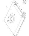
- FIG. 1 is a partially transparent perspective view showing an air blower according to an embodiment.
- FIG. 2 is a perspective view showing the same air blower.
- FIG. 3 is an exploded perspective view showing the same air blower.
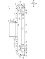
- FIG. 4 is a cross-sectional view of the same air blower as viewed from the front.
- FIG. 5 is a cross-sectional view of the same air blower as viewed from the side.
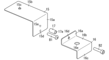
- FIG. 6 is a perspective view showing a mounting structure of a mounting member and an installation bracket in the same air blower.
- FIG. 7 is a perspective view showing a mounting member and an installation bracket in the same air blower.
- FIG. 8 is a perspective view showing a mounting structure of an installation bracket in the same air blower.
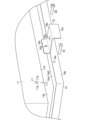
- FIG. 9 is a diagram showing a construction example of the air blower same as the above.
- This embodiment generally relates to a blower. More specifically, the present disclosure relates to a blower device that includes straightening vanes.
- X-axis, Y-axis, and Z-axis that are orthogonal to each other are defined in FIG. 1 unless otherwise specified.
- one of the two directions along the X-axis is the right direction, and the other direction is the left direction.
- one of the two directions along the Y axis is the forward direction, and the other direction is the rearward direction.
- one of the two directions along the Z axis is the upward direction, and the other direction is the downward direction.
- FIGS. 1 to 5 show an air blower 1 of this embodiment.
- the air blower 1 is used in facilities such as office buildings, offices, stores, factories, or commercial facilities, for example.
- the blower 1 may be used in a dwelling unit of an apartment complex, a detached house, or the like. That is, the blower device 1 is assumed to be installed in buildings such as facilities and houses, but may be installed in structures other than buildings.
- the blower device 1 is attached above the air-conditioned space 9, as shown in FIG.
- a building ceiling 91 exists above the air-conditioned space 9 .
- a plurality of T-bars (framework) 92 arranged in a grid are suspended from the ceiling 91 by suspension bolts 93 .
- a plurality of T-bars 92 assembled in a grid form a plurality of rectangular grids 95 arranged in a grid.
- the standard dimension of the grid 95 is, for example, 600 mm ⁇ 600 mm.
- a system ceiling is constructed by arranging a ceiling panel or the like on each of the grids 95 .
- the blower device 1 is arranged on the grid 95 .
- the air blower 1 sucks air in the air-conditioned space 9 , rectifies the sucked air, and blows it out into the air-conditioned space 9 .
- standard dimensions are dimensions defined by standards of various organizations, manufacturers, countries, and the like.
- the blower device 1 includes a housing 11 and a rectifying plate 12.
- the housing 11 is formed in a box shape having an internal space 110 , and has an intake port 11 d for sending air into the internal space 110 and an opening 11 e for discharging air from the internal space 110 .
- the current plate 12 is arranged between the intake port 11d and the opening 11e.
- the housing 11 is made of hard foam material.
- the air blower 1 having the above configuration can achieve both weight reduction and strength by forming the housing 11 from a rigid foam member.
- the housing 11 is formed using hard polystyrene foam as a hard foam member.
- the rigid expanded polystyrene is preferably expanded polystyrene (expanded polystyrene) with an expansion ratio of 20 times.
- the rigid polystyrene foam has self-extinguishing properties. Note that the expansion ratio of the rigid styrene foam is not limited to a specific value, and the expansion ratio is appropriately selected according to the strength required for the housing 11 .
- the housing 11 has a hollow box shape with an internal space 110 .
- the housing 11 includes an upper frustum portion 11a and a lower column portion 11b, and an internal space 110 is an upper space 111 which is an internal space of the frustum portion 11a and an internal space of the column portion 11b. is composed of a lower space 112 .
- the frustum portion 11a has an outer shell that is substantially in the shape of a truncated quadrangular pyramid (or in the shape of a vertically crushed hemisphere, or in the shape of the upper half of a vertically crushed oblate ellipsoid, or in the shape of a bowl).
- the upper space 111 formed inside the frustum portion 11a also has a substantially quadrangular pyramid shape.
- a cylindrical portion 11c is provided at the center (or vertex) of the upper surface of the frustum portion 11a.
- the central axis of the cylindrical portion 11c extends along the Z-axis, and the cylindrical portion 11c has an intake port 11d with a circular cross section. That is, the intake port 11d has a circular cross-section whose axial direction is the vertical direction along the Z-axis.
- the flange 13 is made of polypropylene (PP) resin.
- the flange 13 includes a cylindrical tubular body 13a and a flange portion 13b.
- the flange portion 13b is formed in a circular frame shape extending from the lower end of the tubular body 13a toward the outside of the tubular body 13a.
- the flange 13 is insert-molded in the intake port 11d so that the tubular body 13a is positioned coaxially with the intake port 11d.
- the cylindrical body 13a is inserted through the intake port 11d, and the upper end of the cylindrical body 13a protrudes upward from the upper end of the intake port 11d.
- the collar portion 13b engages with the inner surface of the cylindrical portion 11c and functions as a retainer to prevent the flange 13 from coming off from the intake port 11d.
- the upper end side of the cylinder 13a is fitted into the end of a duct (not shown).
- the lower end of the intake port 11 d is spatially continuous with the upper space 111 of the internal space 110 . Air sent out from an air conditioner or the like flows through the duct, and the air flowing through the duct blows downward into the upper space 111 of the housing 11 through the cylinder 13a and the intake port 11d.
- the columnar portion 11b has a substantially square columnar outer shell, and the lower space 112 formed inside the columnar portion 11b also has a generally square columnar shape.
- a rectangular opening 11e is formed in the lower surface of the column portion 11b.
- the opening 11e is a square plane along the XY plane (the plane defined by the X axis and the Y axis), and the normal direction of this opening 11e is the direction along the Z axis.
- the housing 11 is formed using rigid styrene foam as a rigid foam member.
- the blower device 1 can achieve both weight reduction and securing of strength.
- the flange 13 that supplies air to the intake port 11d is made of polypropylene resin that is harder than rigid styrene foam.
- the air blower 1 can improve the strength of the periphery of the intake port 11d while suppressing weight increase.
- the straightening plate 12 is formed into a square flat plate shape by resin molding using polypropylene resin as a material.
- the rectifying plate 12 has a first surface 12a and a second surface 12b that face each other in the thickness direction. placed in That is, the rectifying plate 12 is made of polypropylene resin, which is harder than rigid styrene foam.
- the current plate 12 is attached to the inner surface of the housing 11 in the inner space 110 by four attachment members 15, as shown in FIGS.
- Two mounting members 15 are mounted side by side in the front-rear direction on the right inner surface of the column portion 11b (the right inner surface of the column portion 11b facing the lower space 112).
- Two mounting members 15 are mounted side by side in the front-rear direction on the left inner surface of the column portion 11b (the left inner surface of the column portion 11b facing the lower space 112). That is, two mounting members 15 are arranged side by side in the front-rear direction on each of a pair of inner side surfaces of the column body portion 11b facing each other.
- the mounting member 15 is formed into an L shape by bending a stainless steel alloy flat plate.
- the mounting member 15 includes a rectangular plate-like fixing piece 15a corresponding to one side of the L shape, and a rectangular plate-like hanging piece 15b corresponding to the other side of the L shape.
- the fixed piece 15a is along the ZY plane (a plane defined by the Z axis and the Y axis) and has a rectangular plate shape extending along the Z axis.
- the fixed piece 15a has a screw hole 15d and a screw hole 15e (see FIG. 7) positioned side by side along the Z axis.
- Each of the screw holes 15d and 15e is formed along the X-axis, and the screw hole 15e is positioned above the screw hole 15d.
- the fixing piece 15a is attached to the inner surface of the columnar body portion 11b facing the lower space 112 with a screw B1.
- the screw B1 is inserted from the outer surface of the frame 14 through the through hole 14e (see FIG. 8) of the frame 14 and the through hole 11f (see FIG.
- each of the through holes 14e and 11f is formed along the X-axis, and each of the through holes 14e and 11f has a circular cross-sectional shape.
- the hanging piece 15b has a rectangular plate shape along the XY plane, and extends from the upper end of the fixed piece 15a toward the inside of the internal space 110 along the X axis.
- the lower surface of the hanging piece 15b faces the first surface 12a of the current plate 12. As shown in FIG.
- the current plate 12 is attached to the hanging piece 15b so that the first surface 12a contacts the lower surface of the hanging piece 15b.
- the hanging piece 15b has a through hole 15c formed along the Z-axis.
- the cross-sectional shape of the through-hole 15c is circular.
- a disk-shaped base 12c is provided at each of the four corners of the rectangular first surface 12a of the straightening plate 12, and a cylindrical shaft portion 12d extending along the Z-axis is provided on the upper surface of the base 12c. formed.
- the shaft portion 12d is inserted through the through-hole 15c from below, and is fixed to the hanging piece 15b by caulking or a nut. That is, the current plate 12 is suspended and fixed to the inner surface of the housing 11 in the internal space 110 by the mounting member 15 .
- the first surface 12a of the straightening plate 12 is formed with four shaft portions 12d corresponding to the four vertices of the rectangle.
- the four shaft portions 12d and the four mounting members 15 correspond one-to-one, and the four shaft portions 12d are fixed to the four mounting members 15, respectively. That is, four locations on the first surface 12 a of the current plate 12 that are not located on the same line are attached to the inner surface of the housing 11 via the attachment members 15 . In other words, at least three locations on the first surface 12 a of the current plate 12 that are not aligned on the same line are attached to the inner surface of the housing 11 . Therefore, even when air flowing through the internal space 110 collides with the straightening vane 12 and stress is generated in the straightening vane 12 , the bending of the straightening vane 12 can be suppressed.
- the shaft portion 12d of the first surface 12a of the rectifying plate 12 is fixed to the mounting member 15, and the mounting member 15 suspends and fixes the rectifying plate 12 to the inner surface of the housing 11. Therefore, the mounting member 15 and the shaft portion 12 d are shielded from below the blower device 1 by the main body of the current plate 12 . As a result, even if a person looks up at the blower 1 from below, the attachment member 15 and the shaft portion 12d can be hidden from the person, and the design of the blower 1 can be improved.
- the frame 14 is a rectangular frame (frame) having an L-shaped cross section and is produced by resin molding using polypropylene resin.
- the frame 14 has a base 14a and an upright wall 14b.
- the base portion 14a is a flat plate along the XY plane and is formed in the shape of a rectangular frame.
- the standing wall 14b is formed in a rectangular frame shape by a flat plate extending upward from the outer peripheral edge of the base portion 14a over the entire circumference of the base portion 14a.
- the frame body 14 is fitted into the lower end of the housing 11.
- the peripheral edge of the opening 11e of the housing 11 is in contact with the upper surface of the base 14a, and the side surface of the lower end of the column 11b is in contact with the inner peripheral surface of the vertical wall 14b.
- the base 14a extends along the XY plane so as to narrow the rectangular opening 11e formed by the lower ends of the left wall, right wall, front wall, and rear wall of the housing 11. That is, the base portion 14a constitutes a throttle portion 14d that narrows the opening 11e.
- the narrowed portion 14d narrows the internal space 110 toward the periphery of the blower port 14c. That is, the rectangular opening surrounded by the base portion 14a (throttle portion 14d) is the blower port 14c.
- FIGS. 1 and 3 Two installation brackets 16 are attached to the right outer surface of the column portion 11b so as to line up in the front-rear direction. Two installation brackets 16 are attached to the left outer surface of the column portion 11b so as to be aligned in the front-rear direction. That is, two mounting brackets 16 are arranged side by side in the front-rear direction on each of a pair of outer side surfaces of the column body portion 11b facing each other.
- the installation bracket 16 is formed by bending a stainless steel alloy flat plate.
- the installation bracket 16 includes a fixing piece 16a, a supporting piece 16b, and a clamping piece 16c.
- Each of the fixing piece 16a, the supporting piece 16b, and the clamping piece 16c has a rectangular plate shape.
- the fixed piece 16a extends upward along the Z-axis from the first end of the support piece 16b.
- the clamping piece 16c extends downward along the Z-axis from the second end (the end opposite to the first end) of the support piece 16b.
- the fixed piece 16a is along the ZY plane (a plane defined by the Z axis and the Y axis) and has a rectangular plate shape extending along the Z axis.
- a through hole 16d is formed in the fixed piece 16a along the X axis.
- the cross-sectional shape of the through hole 16d is circular.
- the fixed piece 16a and the fixed piece 15a face each other along the X-axis with the column portion 11b interposed therebetween.
- a through hole 11g (see FIG. 8) is formed in the column portion 11b along the X-axis, and a cylindrical spacer 17 (see FIGS. 6 to 8) having an insertion hole 17a is formed in the through hole 11g. is embedded.
- a spacer 17 is provided between the fixed piece 16a and the fixed piece 15a, and penetrates the through hole 11g of the column portion 11b along the X axis.
- the through hole 16d of the fixing piece 16a, the insertion hole 17a of the spacer 17, and the screw hole 15e of the fixing piece 15a are coaxially positioned along the X axis.
- the through-hole 16d of the fixed piece 16a and the screw hole 15e of the fixed piece 15a face each other along the X-axis with the through-hole 17a of the spacer 17 interposed therebetween.
- the screw B2 is inserted through the through hole 16d of the fixed piece 16a and the through hole 17a of the spacer 17, and screwed into the screw hole 15e of the fixed piece 15a. attached to the exterior of the
- the support piece 16b has a rectangular plate shape along the XY plane, and extends along the X axis from the lower end of the fixed piece 16a toward the outside of the column portion 11b.
- a through hole 16e is formed in the support piece 16b along the Z axis.
- the cross-sectional shape of the through hole 16e is circular.
- the clamping piece 16c is in the shape of a rectangular plate extending downward along the Z-axis from the outer end of the support piece 16b along the ZY plane.
- the supporting piece 16b is placed on the upper surface of the T-bar 92 (see FIG. 9), and the holding piece 16c sandwiches the T-bar 92 from the side together with the vertical wall 14b of the frame 14. As shown in FIG.
- the support piece 16b is preferably attached to the T-bar 92 with a bolt passing through the through hole 16e from above.
- the blower device 1 does not need to be suspended from the ceiling 91 by the hanger 94 (see FIG. 9), and can be arranged on the grid 95 without using the hanger 94 .
- the installation of the blower device 1 can be carried out as C construction, which is simpler than A construction and B construction, and the workability can be improved.
- the blower device 1 may be suspended from the ceiling 91 by a hanging tool 94 and arranged on the grid 95 .
- a gap forming the communicating portion 116 (see FIGS. 1, 4 and 5) is formed. That is, outside the rectifying plate 12, in the internal space 110, a communication portion 116 having a rectangular frame shape connects the upper space 111, which is the space on the side of the first surface 12a, and the lower space 112, which is the space on the side of the second surface 12b. is formed.
- the communicating portion 116 may be formed along the entire periphery of the current plate 12, or may be formed along only a pair of sides facing each other along the X-axis or the Y-axis.
- the air blower 1 can make the air blown out from the blower port 14c into a directional airflow by the narrowed portion 14d.
- the housing 11 of the blower device 1 has an expansion space 113 (see FIGS. 1, 4 and 5) in order to suppress a decrease in the blowing efficiency.
- the internal space 110 includes the expansion space 113.
- the expansion space 113 has a shape that expands as it approaches the current plate 12 from the intake port 11d.
- the frustum portion 11a makes the upper space 111 of the internal space 110 substantially in the shape of a truncated quadrangular pyramid.
- the intake port 11d is positioned at the top of the upper space 111, and the upper space 111 gradually widens downward from the intake port 11d. That is, in the internal space 110 , the upper space 111 functions as an expansion space 113 .
- the inner space 110 is surrounded by the inner surface of the hollow housing 11 , the inner surface of the frustum portion 11 a of the housing 11 is the upper inner surface 114 , and the inner surface of the column portion 11 b of the housing 11 is the lower inner surface 115 .
- the upper inner surface 114 laterally and upwardly surrounds the expansion space 113 (upper space 111 ), and the lower inner surface 115 laterally surrounds the lower space 112 .
- the upper inner surface 114 is composed of a curved surface.
- the curved surface forming the upper inner surface 114 is preferably configured as follows.
- a direction in which air is fed into the expansion space 113 (internal space 110) from the intake port 11d is defined as a first direction
- a direction orthogonal to the first direction is defined as a second direction.
- the first direction is the vertical direction along the Z axis
- the second direction is the direction along the XY plane.
- the direction of the normal line of the curved surface is from the first direction (direction along the Z-axis) to the second direction (direction along the XY plane) as it approaches the current plate 12 from the air inlet 11d on the curved surface. Change.
- the curved surface forming such an upper inner surface 114 is a substantially hemispherical surface (for example, a curved surface like the surface of a vertically flattened hemisphere, or a curved surface like the surface of the upper half of an oblate ellipsoid that is vertically flattened). , or bowl-shaped. Also, the cross-sectional area of such expansion space 113 on the XY plane gradually increases along the Z-axis downward.
- the air supplied downward from the air intake port 11d into the upper space 111 not only flows directly downward from the air intake port 11d and collides with the first surface 12a of the straightening plate 12, but also flows from the air intake port 11d. It also becomes an air current that flows downward while gradually expanding along the upper inner surface 114 and collides with the first surface 12 a of the current plate 12 . Since the upper inner surface 114 gradually expands as it progresses downward, the upper space 111 is less likely to have a dead zone in which air hardly flows.
- the air that collides with the first surface 12a of the straightening plate 12 flows along the first surface 12a, passes through the communicating portion 116 from top to bottom, then advances toward the air blow port 14c and downward from the air blow port 14c. Blow out.
- the air blower 1 can reduce the pressure loss of the air inside the housing 11 and improve the air blowing efficiency.
- the upper inner surface 114 is curved, and the airflow generated in the expansion space 113 flows smoothly due to the curved surface, so that the ventilation efficiency can be further improved.
- the angle formed by the normal to the curved surface of the upper inner surface 114 with respect to the Z axis gradually increases as the curved surface approaches the straightening plate 12 from the intake port 11d.
- the position of the lower end of the upper inner surface 114 (the boundary between the upper inner surface 114 and the lower inner surface 115) is above the position of the rectifying plate 12. That is, the internal space 110 has an expansion space 113 between the intake port 11 d and the current plate 12 . Therefore, the air blower 1 does not need to widen the lower space 112, and can suppress the enlargement of an apparatus.
- the outer peripheral surface of the housing 11 widens as it approaches the current plate 12 from the intake port 11d. That is, the upper portion of the housing 11 has a shape similar (or substantially similar) to the shape of the upper space 111 . Therefore, the blower device 1 can ensure sufficient strength while the thickness of the housing 11 is relatively thin.
- the inner surface of the housing 11 is preferably waterproofed.
- the waterproofing applied to the inner surface of the housing 11 is, for example, attaching a waterproof sheet (rubber sheet, etc.) or applying a waterproof film (urethane coating, FRP (Fiber Reinforced Plastics) coating, etc.). .
- waterproofing the inner surface of the housing 11 it is possible to prevent the hard foam member of the housing 11 from deteriorating due to dew condensation and humidity in the internal space 110 . If the air blower 1 is configured to blow out mist-containing air from the blower port 14c, waterproofing is more effective.
- the rigid foam member that is the material of the housing 11 may be other than rigid polystyrene foam, is lighter than metal such as aluminum or stainless alloy, and is suitable for forming a part of the blower device 1. Any foam member having sufficient strength may be used. Moreover, it is preferable that the hard foam member has self-extinguishing properties.
- the materials of the current plate 12, the flange 13, and the frame 14 may be, for example, ABS (acrylonitrile-butadiene-styrene) resin other than polypropylene resin.
- the extended space such as the extended space 113 does not have to be generated over the entire area of the upper space such as the upper space 111 .
- the extension space may be created only above the head space.
- the expansion space may not be formed over the entire circumference on the XY plane.
- the current plate 12 may be configured to be movable along the XY plane.
- the straightening plate 12 is moved along the XY plane within the internal space 110 by a drive mechanism having an actuator such as an electric actuator, a pneumatic actuator, or a hydraulic actuator, and the straightening plate 12 moves on the XY plane.
- the slide position which is the position of can be made variable. By changing the sliding position of the rectifying plate 12, the directivity of the air blown from the blower port 14c of the blower device 1 can be controlled.
- the diaphragm portion 14d may be configured to narrow the opening 11e of the housing 11.
- the narrowed portion 14d may be configured to narrow the part of the internal space 110 on the side of the blower port 14c so as to narrow the internal space 110 toward the periphery of the blower port 14c.
- the narrowed portion 14d may have a shape that gradually narrows downward from the opening 11e.
- the blower device 1 may further include a blower that supplies air to the intake port 11d.
- the air blower 1 does not need to receive air sent out from an air conditioner or the like through a duct, and piping work or the like is not required. As a result, the construction for mounting the blower 1 on the ceiling or the like can be easily performed.
- the current plate 12 is a single plate member, a plurality of plate members may be used as the current plate.
- the structure to which the blower device 1 is attached is not limited to the ceiling 91, and may be another structure such as a frame provided above the air-conditioned space 9.
- the air blower (1) of the first aspect according to the above embodiment includes a housing (11) and a current plate (12).
- the housing (11) is formed in the shape of a box having an internal space (110), and has an air intake port (11d) for sending air into the internal space (110) and air to the outside of the internal space (110). It has an opening (11e) for exhaling.
- the current plate (12) is arranged between the intake port (11d) and the opening (11e).
- the housing (11) is made of rigid foam material.
- the blower device (1) described above can achieve both weight reduction and strength.
- the rectifying plate (12) is preferably made of resin harder than the hard foam member.
- the blower device (1) described above can suppress the bending of the rectifying plate (12) while suppressing the increase in weight.
- the blower device (1) of the third aspect according to the above embodiment preferably further comprises a flange (13) for supplying air to the air inlet (11d) in the first or second aspect.
- the flange (13) is made of resin harder than the rigid foam member.
- the blower device (1) described above can improve the strength of the peripheral edge of the intake port (11d) while suppressing the increase in weight.
- the rectifying plate (12) has a first surface facing the air inlet (11d). (12a) and a second surface (12b) facing the opening (11e). At least three locations on the first surface (12a) that are not on the same line are mechanically connected to the inner surface of the housing (11).
- the blower device (1) described above can suppress the bending of the current plate (12) and improve the design of the blower device (1).
- the blower device (1) of the fifth aspect according to the above-described embodiment, in the fourth aspect, comprises at least three attachment members (15 ) is preferably further provided.
- the blower device (1) described above can suppress the bending of the current plate (12).
- the blower device (1) of the sixth aspect according to the above embodiment preferably further comprises a frame (14) surrounding the opening (11e) in any one of the first to fifth aspects.
- the frame (14) is arranged in a grid (95) composed of a plurality of frameworks (92) arranged in a grid.
- the dimensions of the outer circumference of the frame (14) correspond to the standard dimensions of the grid (95).
- the blower device (1) described above can improve workability.
- the air blower (1) of the seventh aspect is such that the internal space (110) extends from the air inlet (11d) to the rectifying plate (12). It is preferred to have an expansion space (113) that widens as it approaches .
- the blower device (1) described above can reduce the air pressure loss in the housing (11) and improve the blowing efficiency.
- the inner surface of the housing (11) is waterproofed. preferable.
- the blower device (1) described above can suppress deterioration of the rigid foam member of the housing (11) due to dew condensation and humidity in the internal space (110).
- the blower device (1) of the ninth aspect according to the above-described embodiment preferably further includes a narrowed portion (14d) that narrows the opening (11e).
- the air blower (1) described above can make the blown air a directional airflow.
- Reference Signs List 1 air blower 11 housing 11d air inlet 11e opening 110 internal space 113 expansion space 12 straightening plate 12a first surface 12b second surface 13 flange 14 frame 14d diaphragm 15 mounting member 92 T-bar (framework) 95 grid
Landscapes
- Engineering & Computer Science (AREA)
- Chemical & Material Sciences (AREA)
- Combustion & Propulsion (AREA)
- Mechanical Engineering (AREA)
- General Engineering & Computer Science (AREA)
- Structures Of Non-Positive Displacement Pumps (AREA)
Priority Applications (1)
| Application Number | Priority Date | Filing Date | Title |
|---|---|---|---|
| JP2023566190A JPWO2023106044A1 (https=) | 2021-12-10 | 2022-11-15 |
Applications Claiming Priority (2)
| Application Number | Priority Date | Filing Date | Title |
|---|---|---|---|
| JP2021201151 | 2021-12-10 | ||
| JP2021-201151 | 2021-12-10 |
Publications (1)
| Publication Number | Publication Date |
|---|---|
| WO2023106044A1 true WO2023106044A1 (ja) | 2023-06-15 |
Family
ID=86730389
Family Applications (1)
| Application Number | Title | Priority Date | Filing Date |
|---|---|---|---|
| PCT/JP2022/042325 Ceased WO2023106044A1 (ja) | 2021-12-10 | 2022-11-15 | 送風装置 |
Country Status (2)
| Country | Link |
|---|---|
| JP (1) | JPWO2023106044A1 (https=) |
| WO (1) | WO2023106044A1 (https=) |
Citations (9)
| Publication number | Priority date | Publication date | Assignee | Title |
|---|---|---|---|---|
| JPS5839422U (ja) * | 1981-09-10 | 1983-03-15 | 松下電器産業株式会社 | 埋込形空気調和機 |
| JPS63215743A (ja) * | 1987-03-03 | 1988-09-08 | Sanyo Electric Co Ltd | 発泡ポリスチレン成形品 |
| JPH0367949A (ja) * | 1989-08-05 | 1991-03-22 | Matsushita Seiko Co Ltd | 空調用吹出グリル |
| JPH0490841U (https=) * | 1990-11-30 | 1992-08-07 | ||
| JPH0618084A (ja) * | 1992-07-02 | 1994-01-25 | Mitsubishi Electric Corp | 空調用給排気グリル |
| JPH09303296A (ja) * | 1996-05-14 | 1997-11-25 | Mitsubishi Electric Corp | 送風機 |
| JPH10311551A (ja) * | 1997-05-14 | 1998-11-24 | Matsushita Seiko Co Ltd | 空気調和機 |
| JP2003014284A (ja) * | 2001-06-29 | 2003-01-15 | Matsushita Seiko Co Ltd | 換気装置 |
| JP2021024308A (ja) * | 2019-07-31 | 2021-02-22 | 近畿車輌株式会社 | 鉄道車両の空調ダクトおよびその製造方法 |
Family Cites Families (2)
| Publication number | Priority date | Publication date | Assignee | Title |
|---|---|---|---|---|
| JP3446129B2 (ja) * | 1995-12-27 | 2003-09-16 | 昭和電工株式会社 | 換気兼熱交換装置 |
| JP3596219B2 (ja) * | 1997-03-18 | 2004-12-02 | 三菱電機株式会社 | 空調用送風装置 |
-
2022
- 2022-11-15 JP JP2023566190A patent/JPWO2023106044A1/ja active Pending
- 2022-11-15 WO PCT/JP2022/042325 patent/WO2023106044A1/ja not_active Ceased
Patent Citations (9)
| Publication number | Priority date | Publication date | Assignee | Title |
|---|---|---|---|---|
| JPS5839422U (ja) * | 1981-09-10 | 1983-03-15 | 松下電器産業株式会社 | 埋込形空気調和機 |
| JPS63215743A (ja) * | 1987-03-03 | 1988-09-08 | Sanyo Electric Co Ltd | 発泡ポリスチレン成形品 |
| JPH0367949A (ja) * | 1989-08-05 | 1991-03-22 | Matsushita Seiko Co Ltd | 空調用吹出グリル |
| JPH0490841U (https=) * | 1990-11-30 | 1992-08-07 | ||
| JPH0618084A (ja) * | 1992-07-02 | 1994-01-25 | Mitsubishi Electric Corp | 空調用給排気グリル |
| JPH09303296A (ja) * | 1996-05-14 | 1997-11-25 | Mitsubishi Electric Corp | 送風機 |
| JPH10311551A (ja) * | 1997-05-14 | 1998-11-24 | Matsushita Seiko Co Ltd | 空気調和機 |
| JP2003014284A (ja) * | 2001-06-29 | 2003-01-15 | Matsushita Seiko Co Ltd | 換気装置 |
| JP2021024308A (ja) * | 2019-07-31 | 2021-02-22 | 近畿車輌株式会社 | 鉄道車両の空調ダクトおよびその製造方法 |
Also Published As
| Publication number | Publication date |
|---|---|
| JPWO2023106044A1 (https=) | 2023-06-15 |
Similar Documents
| Publication | Publication Date | Title |
|---|---|---|
| AU2016201838B2 (en) | Ceiling-Embedded Air Conditioner | |
| CN107449071A (zh) | 空调设备的室外机 | |
| JPWO2011007541A1 (ja) | 換気空調装置 | |
| WO2023106044A1 (ja) | 送風装置 | |
| JP4297819B2 (ja) | 天井埋込型空気調和装置 | |
| US6950526B2 (en) | Sound masking and paging system | |
| JP5087688B2 (ja) | ソックダクト吊下式置換空調用吹出ユニット | |
| JP2018091620A (ja) | 天井埋込型空気調和機 | |
| JP2016070614A (ja) | 天井埋込型空気調和機 | |
| JP5317515B2 (ja) | 換気システム | |
| JPH1073310A (ja) | 多機能カセット型空調ユニット | |
| JP6635846B2 (ja) | 建物の空調設備 | |
| JP6375837B2 (ja) | 天井埋込型空気調和機 | |
| JP3878820B2 (ja) | 換気装置 | |
| JP6020810B2 (ja) | 空気調和機 | |
| JPH10281521A (ja) | レンジフード | |
| JP2004239446A (ja) | 空気調和機 | |
| JP2001182961A (ja) | 空気調和機 | |
| JP2005331184A (ja) | 空調吹出口ユニット | |
| JP2014070774A (ja) | 空気調和機 | |
| WO2019127907A1 (zh) | 空调室外机及空调机组 | |
| JP2012032035A (ja) | 空気調和装置 | |
| JP2005188768A (ja) | 2方向天井埋込型空気調和装置 | |
| JPH06307691A (ja) | 床下空調対応送風機 | |
| JP2016038117A (ja) | 吹出チャンバ装置およびダクト型空気調和機 |
Legal Events
| Date | Code | Title | Description |
|---|---|---|---|
| 121 | Ep: the epo has been informed by wipo that ep was designated in this application |
Ref document number: 22903975 Country of ref document: EP Kind code of ref document: A1 |
|
| ENP | Entry into the national phase |
Ref document number: 2023566190 Country of ref document: JP Kind code of ref document: A |
|
| NENP | Non-entry into the national phase |
Ref country code: DE |
|
| 122 | Ep: pct application non-entry in european phase |
Ref document number: 22903975 Country of ref document: EP Kind code of ref document: A1 |