WO2023105987A1 - 蓄電素子 - Google Patents
蓄電素子 Download PDFInfo
- Publication number
- WO2023105987A1 WO2023105987A1 PCT/JP2022/040588 JP2022040588W WO2023105987A1 WO 2023105987 A1 WO2023105987 A1 WO 2023105987A1 JP 2022040588 W JP2022040588 W JP 2022040588W WO 2023105987 A1 WO2023105987 A1 WO 2023105987A1
- Authority
- WO
- WIPO (PCT)
- Prior art keywords
- electrode
- container
- bodies
- pair
- electrode bodies
- Prior art date
Links
- 238000003860 storage Methods 0.000 title claims abstract description 89
- 239000000463 material Substances 0.000 claims description 37
- 238000004804 winding Methods 0.000 claims description 36
- 230000000712 assembly Effects 0.000 abstract 5
- 238000000429 assembly Methods 0.000 abstract 5
- 230000004048 modification Effects 0.000 description 35
- 238000012986 modification Methods 0.000 description 35
- 239000007774 positive electrode material Substances 0.000 description 12
- 239000008151 electrolyte solution Substances 0.000 description 11
- 239000007773 negative electrode material Substances 0.000 description 11
- -1 polypropylene Polymers 0.000 description 11
- 239000007789 gas Substances 0.000 description 10
- 239000011149 active material Substances 0.000 description 9
- XEEYBQQBJWHFJM-UHFFFAOYSA-N Iron Chemical compound [Fe] XEEYBQQBJWHFJM-UHFFFAOYSA-N 0.000 description 7
- 230000005611 electricity Effects 0.000 description 7
- 229910052751 metal Inorganic materials 0.000 description 7
- 239000002184 metal Substances 0.000 description 7
- 229920001955 polyphenylene ether Polymers 0.000 description 7
- 239000004721 Polyphenylene oxide Substances 0.000 description 6
- 229920013636 polyphenyl ether polymer Polymers 0.000 description 6
- 239000004698 Polyethylene Substances 0.000 description 5
- 238000010586 diagram Methods 0.000 description 5
- 238000004519 manufacturing process Methods 0.000 description 5
- 229920000573 polyethylene Polymers 0.000 description 5
- 229920005989 resin Polymers 0.000 description 5
- 239000011347 resin Substances 0.000 description 5
- 229910000838 Al alloy Inorganic materials 0.000 description 4
- RYGMFSIKBFXOCR-UHFFFAOYSA-N Copper Chemical compound [Cu] RYGMFSIKBFXOCR-UHFFFAOYSA-N 0.000 description 4
- 229910000881 Cu alloy Inorganic materials 0.000 description 4
- PXHVJJICTQNCMI-UHFFFAOYSA-N Nickel Chemical compound [Ni] PXHVJJICTQNCMI-UHFFFAOYSA-N 0.000 description 4
- 239000004696 Poly ether ether ketone Substances 0.000 description 4
- 239000004734 Polyphenylene sulfide Substances 0.000 description 4
- 239000004743 Polypropylene Substances 0.000 description 4
- 229910045601 alloy Inorganic materials 0.000 description 4
- 239000000956 alloy Substances 0.000 description 4
- 229910052782 aluminium Inorganic materials 0.000 description 4
- XAGFODPZIPBFFR-UHFFFAOYSA-N aluminium Chemical compound [Al] XAGFODPZIPBFFR-UHFFFAOYSA-N 0.000 description 4
- 238000005452 bending Methods 0.000 description 4
- 239000010949 copper Substances 0.000 description 4
- 229910052802 copper Inorganic materials 0.000 description 4
- 230000020169 heat generation Effects 0.000 description 4
- 229910052742 iron Inorganic materials 0.000 description 4
- 229910052744 lithium Inorganic materials 0.000 description 4
- 229920001707 polybutylene terephthalate Polymers 0.000 description 4
- 229920002530 polyetherether ketone Polymers 0.000 description 4
- 229920000139 polyethylene terephthalate Polymers 0.000 description 4
- 239000005020 polyethylene terephthalate Substances 0.000 description 4
- 229920000069 polyphenylene sulfide Polymers 0.000 description 4
- 229920001155 polypropylene Polymers 0.000 description 4
- 239000004810 polytetrafluoroethylene Substances 0.000 description 4
- 229920001343 polytetrafluoroethylene Polymers 0.000 description 4
- 238000003466 welding Methods 0.000 description 4
- OKTJSMMVPCPJKN-UHFFFAOYSA-N Carbon Chemical compound [C] OKTJSMMVPCPJKN-UHFFFAOYSA-N 0.000 description 3
- 239000004793 Polystyrene Substances 0.000 description 3
- 230000005856 abnormality Effects 0.000 description 3
- 229920000122 acrylonitrile butadiene styrene Polymers 0.000 description 3
- 239000002131 composite material Substances 0.000 description 3
- 150000001875 compounds Chemical class 0.000 description 3
- 239000000470 constituent Substances 0.000 description 3
- 239000003792 electrolyte Substances 0.000 description 3
- 238000004146 energy storage Methods 0.000 description 3
- 229910052759 nickel Inorganic materials 0.000 description 3
- 239000011255 nonaqueous electrolyte Substances 0.000 description 3
- 229910052723 transition metal Inorganic materials 0.000 description 3
- WHXSMMKQMYFTQS-UHFFFAOYSA-N Lithium Chemical compound [Li] WHXSMMKQMYFTQS-UHFFFAOYSA-N 0.000 description 2
- HBBGRARXTFLTSG-UHFFFAOYSA-N Lithium ion Chemical compound [Li+] HBBGRARXTFLTSG-UHFFFAOYSA-N 0.000 description 2
- 239000004695 Polyether sulfone Substances 0.000 description 2
- RTAQQCXQSZGOHL-UHFFFAOYSA-N Titanium Chemical compound [Ti] RTAQQCXQSZGOHL-UHFFFAOYSA-N 0.000 description 2
- 239000004020 conductor Substances 0.000 description 2
- 238000000354 decomposition reaction Methods 0.000 description 2
- 230000007423 decrease Effects 0.000 description 2
- 238000007599 discharging Methods 0.000 description 2
- 238000010292 electrical insulation Methods 0.000 description 2
- 239000011888 foil Substances 0.000 description 2
- 238000002347 injection Methods 0.000 description 2
- 239000007924 injection Substances 0.000 description 2
- 229910001416 lithium ion Inorganic materials 0.000 description 2
- 229910052748 manganese Inorganic materials 0.000 description 2
- 239000011572 manganese Substances 0.000 description 2
- 229920006393 polyether sulfone Polymers 0.000 description 2
- 229920002223 polystyrene Polymers 0.000 description 2
- 239000010935 stainless steel Substances 0.000 description 2
- 229910001220 stainless steel Inorganic materials 0.000 description 2
- 239000010936 titanium Substances 0.000 description 2
- 150000003624 transition metals Chemical class 0.000 description 2
- 229910018087 Al-Cd Inorganic materials 0.000 description 1
- 229910018188 Al—Cd Inorganic materials 0.000 description 1
- 229910020599 Co 3 O 4 Inorganic materials 0.000 description 1
- 229910000733 Li alloy Inorganic materials 0.000 description 1
- 229910011157 LiMBO Inorganic materials 0.000 description 1
- 229910015118 LiMO Inorganic materials 0.000 description 1
- 229910013275 LiMPO Inorganic materials 0.000 description 1
- 229910015643 LiMn 2 O 4 Inorganic materials 0.000 description 1
- 229910016118 LiMn1.5Ni0.5O4 Inorganic materials 0.000 description 1
- 229920012266 Poly(ether sulfone) PES Polymers 0.000 description 1
- 229920000388 Polyphosphate Polymers 0.000 description 1
- 229910000831 Steel Inorganic materials 0.000 description 1
- JFBZPFYRPYOZCQ-UHFFFAOYSA-N [Li].[Al] Chemical compound [Li].[Al] JFBZPFYRPYOZCQ-UHFFFAOYSA-N 0.000 description 1
- ZVLDJSZFKQJMKD-UHFFFAOYSA-N [Li].[Si] Chemical compound [Li].[Si] ZVLDJSZFKQJMKD-UHFFFAOYSA-N 0.000 description 1
- 229910003481 amorphous carbon Inorganic materials 0.000 description 1
- 230000015572 biosynthetic process Effects 0.000 description 1
- 239000003990 capacitor Substances 0.000 description 1
- 229910052799 carbon Inorganic materials 0.000 description 1
- 239000003575 carbonaceous material Substances 0.000 description 1
- 229910052798 chalcogen Inorganic materials 0.000 description 1
- 239000003610 charcoal Substances 0.000 description 1
- 238000006243 chemical reaction Methods 0.000 description 1
- 239000011530 conductive current collector Substances 0.000 description 1
- 229920001940 conductive polymer Polymers 0.000 description 1
- 238000010276 construction Methods 0.000 description 1
- 238000001816 cooling Methods 0.000 description 1
- 238000002788 crimping Methods 0.000 description 1
- 238000009831 deintercalation Methods 0.000 description 1
- 238000009826 distribution Methods 0.000 description 1
- 230000000694 effects Effects 0.000 description 1
- 239000002803 fossil fuel Substances 0.000 description 1
- 229910052733 gallium Inorganic materials 0.000 description 1
- 239000003502 gasoline Substances 0.000 description 1
- 230000014509 gene expression Effects 0.000 description 1
- 239000011521 glass Substances 0.000 description 1
- 229910002804 graphite Inorganic materials 0.000 description 1
- 239000010439 graphite Substances 0.000 description 1
- 229910021469 graphitizable carbon Inorganic materials 0.000 description 1
- 230000001771 impaired effect Effects 0.000 description 1
- 238000005470 impregnation Methods 0.000 description 1
- 238000009830 intercalation Methods 0.000 description 1
- 238000010030 laminating Methods 0.000 description 1
- JWZCKIBZGMIRSW-UHFFFAOYSA-N lead lithium Chemical compound [Li].[Pb] JWZCKIBZGMIRSW-UHFFFAOYSA-N 0.000 description 1
- 235000013490 limbo Nutrition 0.000 description 1
- 239000003949 liquefied natural gas Substances 0.000 description 1
- 239000007788 liquid Substances 0.000 description 1
- 239000001989 lithium alloy Substances 0.000 description 1
- 229910002102 lithium manganese oxide Inorganic materials 0.000 description 1
- QEXMICRJPVUPSN-UHFFFAOYSA-N lithium manganese(2+) oxygen(2-) Chemical class [O-2].[Mn+2].[Li+] QEXMICRJPVUPSN-UHFFFAOYSA-N 0.000 description 1
- 229910021450 lithium metal oxide Inorganic materials 0.000 description 1
- UIDWHMKSOZZDAV-UHFFFAOYSA-N lithium tin Chemical compound [Li].[Sn] UIDWHMKSOZZDAV-UHFFFAOYSA-N 0.000 description 1
- 229910044991 metal oxide Inorganic materials 0.000 description 1
- 150000004706 metal oxides Chemical class 0.000 description 1
- 150000002739 metals Chemical class 0.000 description 1
- 229910021470 non-graphitizable carbon Inorganic materials 0.000 description 1
- 239000004745 nonwoven fabric Substances 0.000 description 1
- 239000003921 oil Substances 0.000 description 1
- 239000003960 organic solvent Substances 0.000 description 1
- 230000000149 penetrating effect Effects 0.000 description 1
- 229920000447 polyanionic polymer Polymers 0.000 description 1
- 229920005672 polyolefin resin Polymers 0.000 description 1
- 239000001205 polyphosphate Substances 0.000 description 1
- 235000011176 polyphosphates Nutrition 0.000 description 1
- 238000010248 power generation Methods 0.000 description 1
- 238000006479 redox reaction Methods 0.000 description 1
- LIVNPJMFVYWSIS-UHFFFAOYSA-N silicon monoxide Chemical class [Si-]#[O+] LIVNPJMFVYWSIS-UHFFFAOYSA-N 0.000 description 1
- 229910052814 silicon oxide Inorganic materials 0.000 description 1
- 125000006850 spacer group Chemical group 0.000 description 1
- 239000010959 steel Substances 0.000 description 1
- 229920003002 synthetic resin Polymers 0.000 description 1
- 239000000057 synthetic resin Substances 0.000 description 1
- BFKJFAAPBSQJPD-UHFFFAOYSA-N tetrafluoroethene Chemical group FC(F)=C(F)F BFKJFAAPBSQJPD-UHFFFAOYSA-N 0.000 description 1
- 229910052719 titanium Inorganic materials 0.000 description 1
- XLYOFNOQVPJJNP-UHFFFAOYSA-N water Substances O XLYOFNOQVPJJNP-UHFFFAOYSA-N 0.000 description 1
- 239000002023 wood Substances 0.000 description 1
- 239000002759 woven fabric Substances 0.000 description 1
Images


Classifications
-
- H—ELECTRICITY
- H01—ELECTRIC ELEMENTS
- H01G—CAPACITORS; CAPACITORS, RECTIFIERS, DETECTORS, SWITCHING DEVICES OR LIGHT-SENSITIVE DEVICES, OF THE ELECTROLYTIC TYPE
- H01G11/00—Hybrid capacitors, i.e. capacitors having different positive and negative electrodes; Electric double-layer [EDL] capacitors; Processes for the manufacture thereof or of parts thereof
- H01G11/10—Multiple hybrid or EDL capacitors, e.g. arrays or modules
-
- H—ELECTRICITY
- H01—ELECTRIC ELEMENTS
- H01G—CAPACITORS; CAPACITORS, RECTIFIERS, DETECTORS, SWITCHING DEVICES OR LIGHT-SENSITIVE DEVICES, OF THE ELECTROLYTIC TYPE
- H01G11/00—Hybrid capacitors, i.e. capacitors having different positive and negative electrodes; Electric double-layer [EDL] capacitors; Processes for the manufacture thereof or of parts thereof
- H01G11/78—Cases; Housings; Encapsulations; Mountings
-
- H—ELECTRICITY
- H01—ELECTRIC ELEMENTS
- H01M—PROCESSES OR MEANS, e.g. BATTERIES, FOR THE DIRECT CONVERSION OF CHEMICAL ENERGY INTO ELECTRICAL ENERGY
- H01M10/00—Secondary cells; Manufacture thereof
- H01M10/04—Construction or manufacture in general
-
- H—ELECTRICITY
- H01—ELECTRIC ELEMENTS
- H01M—PROCESSES OR MEANS, e.g. BATTERIES, FOR THE DIRECT CONVERSION OF CHEMICAL ENERGY INTO ELECTRICAL ENERGY
- H01M50/00—Constructional details or processes of manufacture of the non-active parts of electrochemical cells other than fuel cells, e.g. hybrid cells
- H01M50/50—Current conducting connections for cells or batteries
- H01M50/531—Electrode connections inside a battery casing
- H01M50/533—Electrode connections inside a battery casing characterised by the shape of the leads or tabs
-
- H—ELECTRICITY
- H01—ELECTRIC ELEMENTS
- H01M—PROCESSES OR MEANS, e.g. BATTERIES, FOR THE DIRECT CONVERSION OF CHEMICAL ENERGY INTO ELECTRICAL ENERGY
- H01M50/00—Constructional details or processes of manufacture of the non-active parts of electrochemical cells other than fuel cells, e.g. hybrid cells
- H01M50/50—Current conducting connections for cells or batteries
- H01M50/531—Electrode connections inside a battery casing
- H01M50/538—Connection of several leads or tabs of wound or folded electrode stacks
-
- H—ELECTRICITY
- H01—ELECTRIC ELEMENTS
- H01M—PROCESSES OR MEANS, e.g. BATTERIES, FOR THE DIRECT CONVERSION OF CHEMICAL ENERGY INTO ELECTRICAL ENERGY
- H01M50/00—Constructional details or processes of manufacture of the non-active parts of electrochemical cells other than fuel cells, e.g. hybrid cells
- H01M50/50—Current conducting connections for cells or batteries
- H01M50/531—Electrode connections inside a battery casing
- H01M50/54—Connection of several leads or tabs of plate-like electrode stacks, e.g. electrode pole straps or bridges
-
- H—ELECTRICITY
- H01—ELECTRIC ELEMENTS
- H01M—PROCESSES OR MEANS, e.g. BATTERIES, FOR THE DIRECT CONVERSION OF CHEMICAL ENERGY INTO ELECTRICAL ENERGY
- H01M50/00—Constructional details or processes of manufacture of the non-active parts of electrochemical cells other than fuel cells, e.g. hybrid cells
- H01M50/50—Current conducting connections for cells or batteries
- H01M50/572—Means for preventing undesired use or discharge
- H01M50/584—Means for preventing undesired use or discharge for preventing incorrect connections inside or outside the batteries
- H01M50/586—Means for preventing undesired use or discharge for preventing incorrect connections inside or outside the batteries inside the batteries, e.g. incorrect connections of electrodes
-
- H—ELECTRICITY
- H01—ELECTRIC ELEMENTS
- H01M—PROCESSES OR MEANS, e.g. BATTERIES, FOR THE DIRECT CONVERSION OF CHEMICAL ENERGY INTO ELECTRICAL ENERGY
- H01M50/00—Constructional details or processes of manufacture of the non-active parts of electrochemical cells other than fuel cells, e.g. hybrid cells
- H01M50/50—Current conducting connections for cells or batteries
- H01M50/572—Means for preventing undesired use or discharge
- H01M50/584—Means for preventing undesired use or discharge for preventing incorrect connections inside or outside the batteries
- H01M50/59—Means for preventing undesired use or discharge for preventing incorrect connections inside or outside the batteries characterised by the protection means
- H01M50/591—Covers
-
- H—ELECTRICITY
- H01—ELECTRIC ELEMENTS
- H01M—PROCESSES OR MEANS, e.g. BATTERIES, FOR THE DIRECT CONVERSION OF CHEMICAL ENERGY INTO ELECTRICAL ENERGY
- H01M50/00—Constructional details or processes of manufacture of the non-active parts of electrochemical cells other than fuel cells, e.g. hybrid cells
- H01M50/50—Current conducting connections for cells or batteries
- H01M50/572—Means for preventing undesired use or discharge
- H01M50/584—Means for preventing undesired use or discharge for preventing incorrect connections inside or outside the batteries
- H01M50/59—Means for preventing undesired use or discharge for preventing incorrect connections inside or outside the batteries characterised by the protection means
- H01M50/593—Spacers; Insulating plates
-
- Y—GENERAL TAGGING OF NEW TECHNOLOGICAL DEVELOPMENTS; GENERAL TAGGING OF CROSS-SECTIONAL TECHNOLOGIES SPANNING OVER SEVERAL SECTIONS OF THE IPC; TECHNICAL SUBJECTS COVERED BY FORMER USPC CROSS-REFERENCE ART COLLECTIONS [XRACs] AND DIGESTS
- Y02—TECHNOLOGIES OR APPLICATIONS FOR MITIGATION OR ADAPTATION AGAINST CLIMATE CHANGE
- Y02E—REDUCTION OF GREENHOUSE GAS [GHG] EMISSIONS, RELATED TO ENERGY GENERATION, TRANSMISSION OR DISTRIBUTION
- Y02E60/00—Enabling technologies; Technologies with a potential or indirect contribution to GHG emissions mitigation
- Y02E60/10—Energy storage using batteries
-
- Y—GENERAL TAGGING OF NEW TECHNOLOGICAL DEVELOPMENTS; GENERAL TAGGING OF CROSS-SECTIONAL TECHNOLOGIES SPANNING OVER SEVERAL SECTIONS OF THE IPC; TECHNICAL SUBJECTS COVERED BY FORMER USPC CROSS-REFERENCE ART COLLECTIONS [XRACs] AND DIGESTS
- Y02—TECHNOLOGIES OR APPLICATIONS FOR MITIGATION OR ADAPTATION AGAINST CLIMATE CHANGE
- Y02P—CLIMATE CHANGE MITIGATION TECHNOLOGIES IN THE PRODUCTION OR PROCESSING OF GOODS
- Y02P70/00—Climate change mitigation technologies in the production process for final industrial or consumer products
- Y02P70/50—Manufacturing or production processes characterised by the final manufactured product
Definitions
- the present invention relates to an electric storage element provided with an electrode body.
- Patent Literature 1 discloses a secondary battery (power storage element) in which a long electrode body (winding core) is accommodated in a container (shell, cover plate).
- the battery module in a battery module for a vehicle, especially a battery module for an electric vehicle that needs to be equipped with a large-capacity storage element, the battery module should be installed under the floor of the vehicle compartment, and considering the cooling efficiency, etc., it should be low-profile.
- Various proposals have been made assuming that a long electric storage element, that is, a flat electric storage element is effective.
- a flat electric storage element the electrode body accommodated in the container becomes longer, and there is a problem that the electrode body is difficult to manufacture.
- the purpose of the present invention is to improve the manufacturability of flat power storage elements.
- a power storage device includes a plurality of electrode bodies each having an electrode plate wound thereon, and a flat container housing the plurality of electrode bodies, The plurality of electrode bodies are arranged in the same space inside the container along a direction orthogonal to the thickness direction of the container, and a pair of adjacent electrode bodies among the plurality of electrode bodies are electrically connected to each other. connected in parallel.
- an electric storage element includes a plurality of electrode bodies in which electrode plates are laminated, and a flat container that houses the plurality of electrode bodies, wherein the plurality of electrode bodies are: A pair of adjacent electrode bodies among the plurality of electrode bodies are arranged in the same space inside the container along a direction perpendicular to the thickness direction of the container, and are electrically connected in parallel. ing.
- the manufacturability of flat electric storage elements can be improved.
- FIG. 1 is a perspective view showing the appearance of a power storage device according to an embodiment.
- FIG. 2 is an exploded perspective view showing each component by disassembling the electric storage device according to the embodiment.
- FIG. 3 is a perspective view showing the configuration of the electrode body according to the embodiment.
- FIG. 4 is a schematic diagram showing a schematic configuration of the positive electrode tab portion according to the embodiment.
- FIG. 5 is a schematic diagram showing a state in which the positive electrode tab portion according to the embodiment is joined to a current collector.
- FIG. 6 is a schematic plan view showing a state in which the positive electrode tab portions are connected to each other by the positive electrode connecting member and the negative electrode tab portions are connected to each other by the negative electrode connecting member in the pair of electrode bodies according to the embodiment.
- FIG. 1 is a perspective view showing the appearance of a power storage device according to an embodiment.
- FIG. 2 is an exploded perspective view showing each component by disassembling the electric storage device according to the embodiment.
- FIG. 3 is a perspective view showing the configuration of
- FIG. 7 is a schematic plan view showing a pair of electrode bodies to which covers according to Modification 1 are respectively attached.
- FIG. 8 is a schematic plan view showing a state in which a pair of covers according to Modification 1 are assembled.
- FIG. 9 is a schematic plan view showing a pair of electrode bodies according to Modification 2.
- FIG. 10 is a schematic plan view showing a plurality of electrode bodies according to Modification 3.
- FIG. 11 is a schematic plan view showing the end portion of the energy storage device according to Modification 4 in the positive direction of the X axis.
- FIG. 12 is a schematic plan view showing the end portion of the energy storage device according to Modification 5 in the positive direction of the X axis.
- FIG. 13 is a schematic cross-sectional view of a power storage device according to Modification 6. As shown in FIG.
- a power storage device includes a plurality of electrode bodies each having an electrode plate wound thereon, and a flat container housing the plurality of electrode bodies, wherein the plurality of electrode bodies are , arranged in the same space inside the container along a direction orthogonal to the thickness direction of the container, and a pair of adjacent electrode bodies among the plurality of electrode bodies are electrically connected in parallel; It is
- the electric storage device since a plurality of electrode bodies are arranged in the same space of the container, one electrode body can be made significantly smaller than the length of the container. . Therefore, each electrode assembly can be easily manufactured. Therefore, manufacturability of a long electric storage element can be improved.
- each electrode body when a plurality of electrode bodies are electrically connected in series within the same space inside the container, each electrode body requires a wall to block the electrolyte, which consumes the space inside the container and increases the energy density. decreases.
- the plurality of electrode bodies arranged in the direction orthogonal to the thickness direction of the container are electrically connected in parallel within the same space, so that a wall is not required and the energy density can be increased. is possible.
- the long wound electrode body has a problem that the gas inside the electrode body generated by the decomposition of the electrolytic solution or the like during the operation of the electric storage element is difficult to be discharged to the outside. In the unlikely event that gas is suddenly discharged due to a short-circuit event or the like, it may become difficult to secure a route to the gas discharge valve.
- the plurality of wound electrode bodies are arranged along the direction orthogonal to the thickness direction of the flat container, one wound electrode body is not elongated in the winding axis direction. It's good. Therefore, even if the wound electrode body is used, the manufacturability of the thin electric storage element and the gas discharge property can be improved.
- the winding axes of the plurality of electrode bodies may be arranged along the same straight line.
- two electrode bodies among the plurality of electrode bodies are defined as a first electrode body and a second electrode body. and the winding axis of the second electrode body are parallel to each other. Furthermore, one end of the first electrode body in the direction perpendicular to the stacking direction of the electrode plates and one end of the second electrode body in the direction perpendicular to the stacking direction of the electrode plates face each other.
- the connection structure for electrically connecting in parallel is simplified compared to the case where the surface in the stacking direction of the first electrode body and the surface in the stacking direction of the second electrode body are arranged to face each other. can be Therefore, the energy density can be increased because the space consumption of the connection structure can be suppressed.
- each of the plurality of electrode bodies includes a set of a positive electrode tab portion and a negative electrode tab portion at both ends in the winding axis direction, and the adjacent pair of In the electrode assembly, pairs of positive electrode tab portions and negative electrode tab portions facing each other may be electrically connected in parallel.
- the end (one end) of one electrode body and the end (other end) of the other electrode body face each other. Therefore, the positive electrode tab portions and the negative electrode tab portions provided at the opposite ends are arranged close to each other. That is, it is possible to further simplify the connection structure for electrically connecting the positive electrode tab portions and the connection structure for electrically connecting the negative electrode tab portions. Therefore, the space consumption of the connection structure can be further suppressed, and the energy density can be further increased.
- each of the plurality of electrode bodies includes tab portions at both ends in the winding axis direction of the electrode body, and the tabs The portion may comprise a bend and an extension extending from said bend.
- each tab portion of the plurality of electrode bodies has a bent portion and an extension portion extending from the bent portion. Since the strength is increased, bending and damage of the tab portion can be suppressed. Accordingly, even if a plurality of electrode bodies vibrate in the same space due to impact or the like, the movement of the electrode bodies can be received by the tab portion having the curved portion. Therefore, damage to the electrode body can be suppressed.
- the extending portions of the plurality of electrode bodies may be connected to each other via a connecting member.
- the extension portions of the plurality of electrode bodies are connected to each other via the connection member, compared with the case where the extension portions are directly connected to each other, the Increases connection strength.
- the connection member since the extension portions of the plurality of electrode bodies are connected to each other via the connection member, compared with the case where the extension portions are directly connected to each other, the Increases connection strength.
- the adjacent electrode bodies are less likely to be relatively displaced, and damage to the electrode bodies can be further suppressed.
- a description will be given in other words to mean that the extension portions are connected to each other via the connection member.
- two adjacent electrode bodies among the plurality of electrode bodies are defined as a first electrode body and a second electrode body, the extending portion of the first electrode body and the extending portion of the second electrode body are connected via a connecting member. It means that it is done.
- a power storage element includes a plurality of electrode bodies in which electrode plates are laminated, and a flat container that houses the plurality of electrode bodies, wherein the plurality of electrode bodies are: A pair of adjacent electrode bodies among the plurality of electrode bodies are arranged in the same space inside the container along a direction perpendicular to the thickness direction of the container, and are electrically connected in parallel. ing.
- the electric storage element since a plurality of electrode bodies are arranged in the same space of the container, one electrode body can be made significantly smaller than the length of the container. Therefore, each electrode assembly can be easily manufactured. Therefore, the manufacturability of a long electric storage element can be improved.
- each electrode body when a plurality of electrode bodies are electrically connected in series within the same space inside the container, each electrode body requires a wall to block the electrolyte, which consumes the space inside the container and increases the energy density. decreases.
- the plurality of electrode bodies arranged in the direction perpendicular to the thickness direction of the container are electrically connected in parallel within the same space, so that a wall is not necessary and the energy density can be increased. .
- each of the plurality of electrode bodies has a set of a positive electrode tab portion and a negative electrode tab portion at both ends in the direction in which the pair of adjacent electrode bodies are arranged.
- the positive electrode tab portions and the negative electrode tab portions of the pairs facing each other may be electrically connected in parallel.
- the end (one end) of one electrode body and the end (other end) of the other electrode body face each other. Therefore, the positive electrode tab portions and the negative electrode tab portions provided at the opposite ends are arranged close to each other. That is, the connection structure for electrically connecting the positive electrode tab portions and the connection structure for electrically connecting the negative electrode tab portions can be simplified. Therefore, the space consumption of the connection structure can be further suppressed, and the energy density can be further increased.
- an insulating cushioning material may be arranged between the positive electrode tab portions and between the negative electrode tab portions.
- connection structure electrically connects the positive electrode tab portions. and the connection structure for electrically connecting the negative electrode tab portions to each other. As a result, short-circuiting between connection structures due to vibration or the like can be suppressed by the cushioning material.
- the electric storage element according to any one of (3), (7), and (8) above may include a cover that covers the positive electrode tab portions and the negative electrode tab portions.
- the positive electrode tab portions and the negative electrode tab portions are covered with the cover, these can be reinforced with the cover. Therefore, impact resistance can be enhanced. Moreover, even if the electric storage element receives an impact from the outside, the cover can suppress short-circuiting between the electrode bodies.
- the direction along the winding axis of the electrode body or the facing direction of the short side of the container is defined as the X-axis direction.
- the direction facing the long side of the container or the thickness direction of the container is defined as the Y-axis direction.
- the thickness direction of the container can be rephrased as the direction in which the flat portions of the electrode bodies are laminated.
- the direction in which the bottom surface of the container body and the top surface of the lid of the container are aligned, or the vertical direction is defined as the Z-axis direction.
- These X-axis direction, Y-axis direction, and Z-axis direction are directions that cross each other (perpendicularly in this embodiment).
- the Z-axis direction may not be the vertical direction depending on the mode of use, the Z-axis direction will be described below for convenience of explanation.
- the X-axis plus direction indicates the arrow direction of the X-axis
- the X-axis minus direction indicates the direction opposite to the X-axis plus direction.
- the Y-axis direction and the Z-axis direction are not strictly the directions or orientations.
- two directions are orthogonal not only means that the two directions are completely orthogonal, but also substantially orthogonal, that is, for example, a difference of about several percent including.
- FIG. 1 is a perspective view showing the appearance of a power storage device 10 according to an embodiment.
- FIG. 2 is an exploded perspective view showing each component by disassembling the electric storage device 10 according to the embodiment.
- the electric storage element 10 is an electric storage element that can be charged with electricity from the outside and discharged with electricity to the outside, and has a substantially rectangular parallelepiped shape in the present embodiment.
- the storage element 10 is a battery used for power storage or power supply.
- the power storage element 10 is used for driving mobile bodies such as automobiles, motorcycles, water crafts, ships, snowmobiles, agricultural machinery, construction machinery, or railway vehicles for electric railways, or for starting engines. Used as a battery or the like.
- the vehicles include electric vehicles (EV), hybrid electric vehicles (HEV), plug-in hybrid electric vehicles (PHEV), and fossil fuel (gasoline, light oil, liquefied natural gas, etc.) vehicles.
- Examples of railway vehicles for the electric railway include electric trains, monorails, linear motor cars, and hybrid trains having both diesel engines and electric motors.
- the power storage device 10 can also be used as a stationary battery or the like for home or business use.
- the storage element 10 is not limited to a non-aqueous electrolyte secondary battery, and may be a secondary battery other than a non-aqueous electrolyte secondary battery, or may be a capacitor.
- the power storage element 10 may be a primary battery that can use stored electricity without being charged by the user, instead of a secondary battery.
- the storage element 10 may be a pouch-type storage element.
- a flattened rectangular parallelepiped (rectangular) power storage element 10 is illustrated, but the shape of the power storage element 10 may be any shape as long as it is flat. Alternatively, it may have a cylindrical shape or the like.
- the storage element 10 includes a container 100, two pairs of electrode terminals 300, and two pairs of external gaskets 400. As shown in FIGS. Two pairs of internal gaskets 500 and two pairs of current collectors 600 are accommodated in the same space inside the container 100 . Specifically, a pair of members (a positive electrode and a negative electrode) are arranged on one end surface of the container 100 in the positive direction of the X axis, and the remaining pair of members (a positive electrode and a negative electrode) are arranged on the other end surface of the container 100 in the negative direction of the X axis. ) are arranged.
- the positive electrode members are arranged in the positive Z-axis direction, and the negative electrode members are arranged in the negative Z-axis direction.
- the members of the negative electrode are arranged in the positive direction of the Z axis, and the members of the positive electrode are arranged in the negative direction of the Z axis.
- a pair of electrode bodies 700 is arranged between each member of the positive electrode and each member of the negative electrode.
- Each electrode body 700 is a wound electrode body, and is arranged such that the winding axes L thereof are aligned along the same straight line. That is, on one end surface and the other end surface of the container 100, the positive electrode members and the negative electrode members are arranged reversed (upside down) when viewed from the direction along the winding axis (viewed in the X-axis direction).
- a cushioning material 810 , a pair of connection members 820 and a pair of covers 830 are arranged between the pair of electrode bodies 700 in the same space inside the container 100 .
- the cushioning material 810 is a porous block-shaped member and is arranged in the central portion in the Z-axis direction between the pair of electrode bodies 700 .
- the cushioning material 810 is, for example, polypropylene (PP), polyethylene (PE), polystyrene (PS), polyphenylene sulfide resin (PPS), polyphenylene ether (PPE (including modified PPE)), polyethylene terephthalate (PET), polybutylene Terephthalate (PBT), polyetheretherketone (PEEK), tetrafluoroethylene/perfluoroalkylvinylether (PFA), polytetrafluoroethylene (PTFE), polyethersulfone (PES), ABS resin, or composite materials thereof It is formed of a resin or the like having electrical insulation such as.
- the cushioning material 810 can reduce the impact when the pair of electrode bodies 700 come close to each other.
- the pair of connection members 820 are flat plate-like conductive members (a positive electrode connection member 821 and a negative electrode connection member 822) that electrically connect the pair of electrode bodies 700 in parallel.
- the positive electrode connecting member 821 is joined (welded) to the opposing positive electrode tab portions 721 of the pair of electrode bodies 700 to electrically connect the positive electrode tab portions 721 to each other.
- the electrode body 700 in the X-axis plus direction and the electrode body 700 in the X-axis minus direction are arranged in the X-axis direction.
- the electrode body 700 in the X-axis plus direction has a positive electrode tab portion 721 at the end portion in the X-axis minus direction.
- the electrode assembly 700 in the negative X-axis direction has a positive electrode tab portion 721 at the end in the positive X-axis direction.
- the two positive electrode tab portions 721 are joined (welded) by a positive electrode connection member 821, and the two positive electrode tabs 721 are electrically connected.
- the negative electrode connection member 822 is joined (welded) to the opposing negative electrode tab portions 722 of the pair of electrode bodies 700 to electrically connect the negative electrode tab portions 722 to each other.
- the electrode body 700 in the X-axis plus direction has a negative electrode tab portion 722 at the end in the X-axis minus direction.
- the electrode assembly 700 in the negative direction of the X-axis has a negative electrode tab portion 722 at the end in the positive direction of the X-axis.
- the two negative electrode tab portions 722 are joined (welded) by a negative electrode connection member 822, and the two negative electrode tabs 722 are electrically connected.
- the pair of electrode bodies 700 may be electrically connected in parallel, and the pair of electrode bodies 700 may be electrically connected without using the connection member 820 .
- the two positive electrode tab portions 721 facing each other are directly connected.
- the two opposing negative electrode tab portions 722 are also directly connected. The positive electrode tab portion 721 and the negative electrode tab portion 722 will be described later.
- connection member 820 is not particularly limited, for example, the positive electrode connection member 821 is formed of a conductive member such as aluminum or an aluminum alloy, similar to the positive electrode base material 741 of the electrode body 700 described later, and the negative electrode connection member 822 is Like the negative electrode base material 751 of the electrode body 700 to be described later, it is made of a conductive material such as copper or a copper alloy.
- the pair of covers 830 covers the positive electrode tab portions 721, the negative electrode tab portions 722, the cushioning material 810, and the pair of connecting members 820 from the Y-axis plus direction and the Y-axis minus direction. It is an insulating cover.
- Each cover 830 is made of, for example, PP, PE, PS, PPS, PPE (including modified PPE), PET, PBT, PEEK, PFA, PTFE, PES, ABS resin, or a composite material thereof. It is made of a resin or the like having properties.
- the cover 830 formed in a corrugated plate shape is illustrated, but the shape of the cover 830 may be any shape, such as a flat plate shape or a box shape. may
- An electrolytic solution (non-aqueous electrolyte) is sealed inside the container 100, but illustration is omitted.
- the type of the electrolytic solution as long as it does not impair the performance of the storage element 10, and various types can be selected.
- spacers disposed laterally, above, or below the pair of electrode bodies 700, insulating films wrapping the pair of electrode bodies 700, and the like may be disposed.
- the container 100 is a rectangular parallelepiped (rectangular or box-shaped) case elongated in the X-axis direction. Specifically, the container 100 is a flat case that is elongated in the X-axis direction and whose length (thickness) in the Y-axis direction is shorter than the length in the Z-axis direction.
- the pair of electrode bodies 700 described above are arranged along the direction (X-axis direction) orthogonal to the thickness direction (Y-axis direction) of the container 100 .
- the opposite end surfaces in the X-axis direction are short side surfaces 101, and the opposite end surfaces in the Y-axis direction are long side surfaces 102, respectively.
- the pair of short side surfaces 101 are one end surface and the other end surface in the X-axis direction on which the above-described positive electrode members and negative electrode members are provided.
- the end surface in the positive Z-axis direction is the top surface 103
- the end surface in the negative Z-axis direction is the bottom surface 104 .
- the flat shape of the container 100 means a flat shape. At this time, the length of the long side 102 in the X-axis direction of the container 100 is longer than the length of the short side 101 in the Y-axis direction.
- the container 100 has a container main body 110 and a lid 120, and the container main body 110 and the lid 120 are assembled to form a rectangular parallelepiped shape.
- the container body 110 has a pair of long sides 102 and a bottom surface 104 .
- the lid 120 has a pair of short side surfaces 101 and a top surface 103 .
- the container body 110 is a substantially U-shaped sheet metal with an open top when viewed in the X-axis direction.
- the container body 110 has flat rectangular long side walls forming a pair of long side surfaces 102 at both ends in the Y-axis direction, and flat rectangular rectangular bottom surfaces 104 at the ends in the negative Z-axis direction. It has a shaped bottom wall.
- the lid body 120 is a substantially U-shaped sheet metal with an open bottom when viewed in the Y-axis direction.
- the lid body 120 has flat and rectangular short side walls forming a pair of short side surfaces 101 at both ends in the X-axis direction, and a flat plate-like and rectangular top surface 103 at the end in the positive Z-axis direction. It has a rectangular ceiling wall.
- container body 110 and the lid body 120 are joined by welding or the like to seal the interior.
- the material of container 100 is not particularly limited, but weldable metals such as stainless steel, aluminum, aluminum alloy, iron, and plated steel plate are preferable.
- the lid 120 is formed with a liquid injection part and a gas discharge valve.
- the gas discharge valve is a safety valve that releases the pressure when the pressure inside the container 100 rises excessively.
- the injection part is a part for injecting an electrolytic solution into the inside of the container 100 when the electric storage element 10 is manufactured.
- the electrode terminal 300 is a terminal member (a positive electrode terminal 310 and a negative electrode terminal 320) electrically connected to the electrode body 700 via the current collector 600. That is, the electrode terminal 300 leads the electricity stored in the electrode body 700 to the external space of the storage element 10 and introduces the electricity into the internal space of the storage element 10 to store the electricity in the electrode body 700 .
- the material of the electrode terminal 300 is not particularly limited, for example, the electrode terminal 300 (the positive terminal 310 and the negative terminal 320) is made of a conductive material such as aluminum, aluminum alloy, copper, or copper alloy.
- the electrode terminal 300 is connected (joined) to the current collector 600 and attached to the lid 120 by caulking, welding, or the like.
- the electrode terminal 300 is provided with a shaft portion 330, and the shaft portion 330 is crimped while penetrating the outer gasket 400, the inner gasket 500, and the current collector 600, whereby the current collector is 600 is connected (joined).
- the electrode terminals 300 are not limited to those of this embodiment, and may be formed of bolts, for example.
- the current collectors 600 are arranged in pairs on both sides of the electrode assembly 700 in the X-axis direction, and are connected (joined) to the electrode assembly 700 and the electrode terminals 300 to electrically connect the electrode assembly 700 and the electrode terminals 300. They are conductive current collectors (positive electrode current collector 610 and negative electrode current collector 620). Specifically, the current collector 600 integrally has a single connection portion 630 and a second connection portion 640 .
- the first connection portion 630 is connected (joined) to the tab portion 720 of the electrode body 700 by welding, crimping, or the like.
- the second connection portion 640 is connected (joined) to the electrode terminal 300 by caulking, welding, or the like and fixed to the lid 120 .
- the first connection portion 630 and the second connection portion 640 are flat plate-like portions, and are formed by bending a single sheet metal.
- the material of the current collector 600 is not particularly limited.
- 620 is formed of a conductive member such as copper or copper alloy, like the negative electrode base material 751 of the electrode body 700 described later.
- the outer gasket 400 is arranged between the lid 120 of the container 100 and the electrode terminal 300 , and is a plate-shaped and rectangular insulating seal that insulates and seals between the lid 120 and the electrode terminal 300 . It is a stop member.
- the internal gasket 500 is a plate-shaped rectangular insulating seal disposed between the lid 120 and the current collector 600 to insulate and seal between the lid 120 and the current collector 600 . It is a member.
- the outer gasket 400 and the inner gasket 500 are made of, for example, PP, PE, PS, PPS, PPE (including modified PPE), PET, PBT, PEEK, PFA, PTFE, PES, ABS resin, or composite materials thereof. It is formed of a resin or the like having electrical insulation.
- the electrode body 700 is a storage element (power generation element) formed by winding an electrode plate and capable of storing electricity.
- the electrode body 700 is elongated in the X-axis direction and has an oval shape when viewed from the X-axis direction.
- the length of the electrode body 700 in the X-axis direction is, for example, 150 mm or more, specifically about 250 mm to 750 mm. Therefore, the electrode body 700 is longer in the X-axis direction than in the Z-axis direction. However, the shape of the electrode body 700 does not have to be long.
- the length of the electrode body 700 in the X-axis direction may be shorter than the above length.
- the electrode assembly 700 has a body portion 710 and a plurality of tab portions 720 protruding from the body portion 710 , and the tab portions 720 are connected (joined) to the current collector 600 as described above.
- the plurality of tab portions 720 protrude in pairs from each of both end surfaces of the body portion 710 in the X-axis direction.
- a positive electrode tab portion 721 is provided at the end in the positive direction of the Z axis
- a negative electrode tab portion 722 is provided at the end in the negative direction of the Z axis.
- a negative electrode tab portion 722 is provided at the end in the positive direction of the Z axis
- a positive electrode tab portion 721 is provided at the end in the negative direction of the Z axis.
- FIG. 3 is a perspective view showing the configuration of the electrode body 700 according to the embodiment. Specifically, FIG. 3 shows the electrode body 700 in the positive direction of the X-axis among the pair of electrode bodies 700, and the configuration of the electrode body 700 in which the wound state of the electrode plates is partially unfolded. is shown. Since the electrode body 700 in the negative direction of the X-axis basically has the same configuration as the electrode body 700 in the positive direction of the X-axis, the electrode body 700 in the positive direction of the X-axis will be described as an example. The electrode body 700 in the negative direction of the X-axis is different in that the electrode body 700 in the positive direction of the X-axis is reversed when viewed in the Z-axis direction.
- the electrode assembly 700 includes a positive electrode plate 740, a negative electrode plate 750, and separators 761 and 762.
- the positive electrode plate 740 is an electrode plate (electrode plate) in which a positive electrode active material layer 742 is formed on the surface of a positive electrode base material 741, which is a long strip-shaped metal foil made of aluminum, an aluminum alloy, or the like.
- the negative electrode plate 750 is an electrode plate (electrode plate) in which a negative electrode active material layer 752 is formed on the surface of a negative electrode base material 751 which is a long belt-shaped metal foil made of copper, copper alloy, or the like.
- the positive electrode base material 741 and the negative electrode base material 751 nickel, iron, stainless steel, titanium, calcined carbon, conductive polymer, conductive glass, Al—Cd alloy, etc., which are stable against oxidation-reduction reactions during charging and discharging.
- a known material can be used as appropriate.
- a positive electrode active material capable of intercalating and deintercalating lithium ions is used for the positive electrode active material layer 742 .
- a known material, which will be described later, can be used for the negative electrode active material layer 752 .
- polyanion compounds such as LiMPO 4 , LiMSiO 4 , LiMBO 3 (M is one or more transition metal elements selected from Fe, Ni, Mn, Co, etc.), lithium titanate, Spinel-type lithium manganese oxides such as LiMn 2 O 4 and LiMn 1.5 Ni 0.5 O 4 , LiMO 2 (M is one or more transition metals selected from Fe, Ni, Mn, Co, etc. element) and the like can be used.
- negative electrode active materials include lithium metal, lithium alloys (lithium-silicon, lithium-aluminum, lithium-lead, lithium-tin, lithium-aluminum-tin, lithium-gallium, and lithium metal-containing alloys such as Wood's alloys). , alloys that can absorb and release lithium, carbon materials (e.g. graphite, non-graphitizable carbon, easily graphitizable carbon, low-temperature fired carbon, amorphous carbon, etc.), silicon oxides, metal oxides, lithium metal oxides ( Li 4 Ti 5 O 12 , etc.), polyphosphate compounds, or compounds of transition metals and group 14 to group 16 elements, such as Co 3 O 4 and Fe 2 P, which are generally called conversion negative electrodes. .
- lithium alloys lithium-silicon, lithium-aluminum, lithium-lead, lithium-tin, lithium-aluminum-tin, lithium-gallium, and lithium metal-containing alloys such as Wood's alloys.
- the separators 761 and 762 are microporous sheets made of resin.
- any well-known material can be appropriately used as long as the performance of the electric storage element 10 is not impaired.
- a woven fabric, a non-woven fabric, a synthetic resin microporous film made of a polyolefin resin such as polyethylene, etc., which is insoluble in an organic solvent, or the like can be used.
- the electrode body 700 is formed by alternately stacking and winding positive electrode plates 740 and negative electrode plates 750 and separators 761 and 762 . That is, the electrode body 700 is formed by laminating the negative electrode plate 750, the separator 761, the positive electrode plate 740, and the separator 762 in this order and winding them.
- the electrode body 700 is a wound electrode body formed by winding a positive electrode plate 740, a negative electrode plate 750, and the like around a winding axis L extending in the X-axis direction.
- the winding axis L is a virtual axis that serves as a central axis when the positive electrode plate 740, the negative electrode plate 750, and the like are wound. They are parallel straight lines.
- a plurality of protruding pieces 743 protruding outward are arranged in a zigzag pattern in a plan view of the positive electrode plate 740 on both edges of the positive electrode plate 740 in the winding axis direction.
- a plurality of protruding pieces 753 protruding outward are arranged in a zigzag pattern when the negative electrode plate 750 is viewed from above, at both edges of the negative electrode plate 750 in the direction of the winding axis.
- the protruding pieces 743 of the positive electrode plate 740 and the protruding pieces 753 of the negative electrode plate 750 are alternately and repeatedly arranged in the longitudinal direction of the positive electrode plate 740 and the negative electrode plate 750, respectively.
- Each of the projecting pieces 743 and 753 is a portion (active material layer non-formation portion) where the base layer is exposed without forming the active material layer containing the active material.
- a positive electrode tab portion 721 is a portion where the projecting piece 743 of the positive electrode plate 740 overlaps.
- the positive electrode tab portion 721 is formed by stacking a plurality of pieces (protruding pieces 743) of the electrode plates (the positive electrode plate 740) having the same polarity among the plurality of electrode plates (the positive electrode plate 740 and the negative electrode plate 750). It is a part.
- the portion where the projecting piece 753 of the negative electrode plate 750 overlaps is the negative electrode tab portion 722 . That is, the negative electrode tab portion 722 is formed by stacking a plurality of pieces (protruding pieces 753) of the electrode plates (the negative electrode plate 750) having the same polarity among the plurality of electrode plates (the positive electrode plate 740 and the negative electrode plate 750). It is a part.
- the electrode body 700 includes a main body portion 710 constituting the main body of the electrode body 700, and a plurality of tab portions 720 (a positive electrode tab portion 721 and a negative electrode tab portion) protruding from each of both end surfaces of the main body portion 710 in the X-axis direction. 722) and .
- Each tab portion 720 is an active material uncoated portion on which an active material layer is not formed (coated).
- the body portion 710 is formed by winding a portion of the positive electrode plate 740 and the negative electrode plate 750 on which the positive electrode active material layer 742 and the negative electrode active material layer 752 are formed (coated) and separators 761 and 762 .
- This is a columnar portion (active material layer forming portion).
- the body portion 710 has a pair of curved portions 711 on both sides in the Z-axis direction, and has a flat portion 712 that is flat as a whole between the pair of curved portions 711 . It can also be said that the pair of curved portions 711 are arranged at positions sandwiching the flat portion 712 in the Z-axis direction.
- the curved portion 711 is curved in a semicircular arc shape so as to protrude in the Z-axis direction when viewed from the X-axis direction, and is a curved portion extending in the X-axis direction. 120 is arranged opposite to the ceiling wall portion. That is, the pair of curved portions 711 are portions curved so as to protrude from the flat portion 712 toward both sides in the Z-axis direction toward the bottom wall portion of the container body 110 and the top wall portion of the lid 120 when viewed from the X-axis direction. is.
- the flat portion 712 is a rectangular and flat portion that connects the ends of the pair of curved portions 711 and spreads parallel to the XZ plane facing the Y-axis direction. placed facing the part.
- the curved shape of the curved portion 711 is not limited to a semicircular arc shape, and may be a part of an elliptical shape or the like, and may be curved in any way.
- the flat portion 712 is not limited to having a flat outer surface facing the Y-axis direction, and the outer surface may be slightly concave or slightly bulging.
- each tab portion 720 has the same basic structure, the positive electrode tab portion 721 provided on one end face of the body portion 710 in the plus direction of the X axis will be mainly described here, and the other tab portions 720 will be described. Description of is omitted.
- FIG. 4 is a schematic diagram showing a schematic configuration of the positive electrode tab portion 721 according to the embodiment. 4 shows the positive electrode tab portion 721 before being joined to the current collector 600 as viewed in the X-axis direction.
- the number of projecting pieces 743 constituting the positive electrode tab portion 721 is simplified and illustrated.
- the positive electrode tab portion 721 has a bent portion 723 and a pair of extension portions 724 .
- the bent portion 723 is a portion that is continuous with the curved portion 711 of the main body portion 710 . Therefore, the bent portion 723 has a curved shape corresponding to the curved portion 711 .
- a pair of extending portions 724 are portions extending from both ends of the bent portion 723 and continuing to the flat portion 712 of the main body portion 710 . Therefore, the pair of extensions 724 are substantially flat before being joined to the current collector 600 . Curved bends 723 provide greater structural strength than each extension 724, which is flat.
- both ends of the plurality of protruding pieces 743 forming the pair of extending portions 724 are positioned substantially at the same position in the Z-axis direction. are placed in
- FIG. 5 is a schematic diagram showing a state in which the positive electrode tab portion 721 according to the embodiment is joined to the current collector 600. As shown in FIG. Specifically, FIG. 5 is a diagram corresponding to FIG.
- the plurality of protruding pieces 743 forming the pair of extending portions 724 are gathered and bundled at the center (the center in the direction in which the plurality of protruding pieces 743 are arranged). ing. Even after being bundled, both ends of each projecting piece 743 are arranged at approximately the same position in the Z-axis direction. As a result, the electrical resistance for each protruding piece 743 is reduced, and the uniformity of current distribution is enhanced.
- the first connecting portion 630 of the current collector 600 is joined (welded) to the pair of extending portions 724 .
- connection member 820 is also joined (welded) to the extension portion 724 of the tab portion 720 .
- FIG. 6 is a schematic plan view showing a state in which the positive electrode tab portions 721 are connected to each other by the positive electrode connecting member 821 and the negative electrode tab portions 722 are connected to each other by the negative electrode connecting member 822 in the pair of electrode bodies 700 according to the embodiment. is. Illustration of the cover 830 is omitted in FIG. As shown in FIG. 6, the cushioning material 810 is arranged between each positive electrode tab portion 721 and each negative electrode tab portion 722 . That is, since the buffer material 810 is arranged between the positive electrode connection member 821 and the negative electrode connection member 822 , the interference between the positive electrode connection member 821 and the negative electrode connection member 822 can be suppressed by the buffer material 810 .
- the plurality of electrode bodies 700 are arranged in the same space of the container 100 .
- the electric storage element 10 can be thin as a whole. is. If it is thin, even if a nail or the like penetrates the container 100 and contacts the electrode body 700, the contact area is small. Therefore, heat generation caused by this short-circuit resistance can be reduced.
- the plurality of electrode bodies 700 are arranged in the same space inside the container 100 in a direction (X-axis direction) orthogonal to the thickness direction (Y-axis direction) of the container 100 and electrically parallel. It is connected to the.
- the direction orthogonal to the thickness direction of the container 100 is the same direction as the direction orthogonal to the stacking direction of the flat portions of the electrode bodies. Therefore, there is no need for walls that block the electrolyte between the plurality of electrode bodies 700 .
- the long wound electrode body has a problem that the gas inside the electrode body generated by the decomposition of the electrolytic solution or the like during the operation of the electric storage element is difficult to be discharged to the outside.
- the electrolytic solution tends to impregnate the electrode body from the ends (two places) in the winding axial direction of the electrode body.
- a plurality of wound electrode bodies are arranged in one container. As a result, the length of each electrode body in the direction of the winding axis is shortened.
- the number of ends of the electrode body in the direction of the winding axis is increased.
- the number of places in the electrode body that are easily impregnated with the electrolyte solution increases, and the length of impregnation of the electrode body with the electrolyte solution can be shortened.
- one wound electrode body 700 can be arranged in the winding axial direction. You don't have to lengthen it. Therefore, even if the wound electrode body 700 is used, the manufacturability and the gas discharge property of the thin storage device 10 can be improved.
- Two electrode bodies 700 out of the plurality of electrode bodies 700 in which the plurality of electrode bodies 700 are arranged so that the winding axis L extends along the same straight line are defined as a first electrode body 700 and a second electrode body 700.
- the direction in which the winding axis L of the first electrode body 700 extends is the same as the direction in which the winding axis L of the second electrode body 700 extends.
- a configuration is also included in which the end of the first electrode body 700 in the direction in which the winding axis L extends and the end in the direction of the winding axis L of the second electrode body 700 face each other.
- connection structure for electrically connecting in parallel can be simplified. Therefore, the space consumption of the connection structure can be suppressed, and the energy density can be increased.
- connection structure for electrically connecting the positive electrode tab portions 721 and the connection structure (negative electrode connection member 822) for electrically connecting the negative electrode tab portions 722 can be simplified. It is possible. Therefore, the space consumption of the connection structure can be further suppressed, and the energy density can be further increased.
- the connection structure for electrically connecting the positive electrode tab portions 721 and the negative electrode tab portions 722 are electrically connected to each other.
- the cushioning material 810 is also interposed between the connecting structures that are physically connected. That is, the cushioning material 810 can suppress short-circuiting between connection structures caused by vibration or the like.
- the positive electrode tab portions 721 and the negative electrode tab portions 722 are covered with the cover 830 , these can be reinforced with the cover 830 . Therefore, impact resistance can be enhanced. Further, even if power storage element 10 receives an impact from the outside, short circuit between electrode bodies 700 can be suppressed by cover 830 .
- each tab portion 720 of the plurality of electrode bodies 700 has a bent portion 723 and an extension portion 724 extending from the bent portion 723, the bent portion 723 increases the strength of the entire tab portion 720. It is possible to suppress bending and damage of the tab portion. Thus, even if the plurality of electrode bodies 700 vibrate in the same space due to impact or the like, the tab portion 720 having the bent portion 723 can receive the movement of the electrode bodies 700 . Therefore, damage to the electrode body 700 can be suppressed.
- connection strength can be increased compared to the case where the extension portions 724 are directly connected to each other.
- the connection member 820 even if the plurality of electrode bodies 700 vibrate in the same space due to impact or the like, the movement of the electrode bodies 700 can be received by the connection member 820 .
- the adjacent electrode bodies are less likely to be relatively displaced, and damage to the electrode body 700 can be further suppressed.
- the inventors of the present application have found that when the positive electrode tab portion 721 and the negative electrode tab portion 722 are inverted between one end surface and the other end surface of the main body portion 710 of the electrode body 700, the charge/discharge time is greater than when they are not inverted. It has been found that the resistance of the electrode assembly 700 is reduced. That is, in the main body portion 710 of the electrode assembly 700, if the positive electrode tab portion 721 and the negative electrode tab portion 722 provided on one end surface and the positive electrode tab portion 721 and the negative electrode tab portion 722 provided on the other end surface are arranged reversely, It is possible to reduce the resistance of the electrode body 700 during charging and discharging. This is suitable for the electrode body 700 elongated in the direction of the winding axis, which tends to have high resistance.
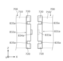
- FIG. 7 is a schematic plan view showing a pair of electrode bodies 700 to which covers 831a and 832a according to Modification 1 are attached.
- FIG. 8 is a schematic plan view showing a state in which a pair of covers 831a and 832a according to Modification 1 are assembled.
- the electrode body 700 is indicated by dashed lines.
- the pair of covers 831 a and 832 a are cap-shaped, are attached to the ends of the electrode body 700 in the X-axis direction, and accommodate the tab portion 720 .
- Each of the covers 831a and 832a may or may not contain a cushioning material.
- a concave portion 833a is formed in the surface of one cover 831a facing the other cover 832a.
- the other cover 832a has a convex portion 834a that fits into the concave portion 833a on the surface facing the one cover 831a.
- the integrity between the pair of covers 831a and 832a is enhanced, and thus the integrity between the pair of electrode bodies 700 is enhanced.
- a pair of cutouts 835a are formed in the covers 831a and 832a to expose the joint position with the connection member 820 in the tab portion 720. As shown in FIG. Therefore, after the pair of electrode bodies 700 are integrated with the pair of covers 831a and 832a, the connection member 820 can be joined (welded) to the tab portion 720 through each notch 835a. As described above, since the pair of covers 831 a and 832 a enhances the integrity of the pair of electrode bodies 700 , the connection member 820 can be stably joined to the tab portion 720 .
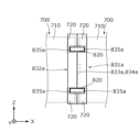
- FIG. 9 is a schematic plan view showing a pair of electrode bodies 700b according to Modification 2. As shown in FIG. In FIG. 9, the outer shape of the container 100 is indicated by broken lines.
- the electrode body 700 in which the tab portion 720, which is the active material uncoated portion, is provided on a part of the main body portion 710 in the Z-axis direction is exemplified.
- Modification 2 illustrates an electrode body 700b in which active material uncoated portions (positive electrode active material uncoated portion 731b and negative electrode active material uncoated portion 732b) are provided over the entire Z-axis direction of main body portion 710b. and explain.
- a pair of electrode bodies 700b are arranged in the X-axis direction so that their winding axes L are aligned on the same straight line.
- Each electrode body 700b is arranged in the same space of the container 100 in such a posture that the positive electrode active material uncoated portion 731b faces the X-axis plus direction and the negative electrode active material uncoated portion 732b faces the X axis minus direction.
- a positive electrode connecting member 821b for electrically connecting the positive electrode active material uncoated portions 731b of the pair of electrode bodies 700b, and an electrically connecting member 821b electrically connecting the negative electrode active material uncoated portions 732b of the pair of electrode bodies 700b.
- a negative electrode connection member 822b that is electrically connected is accommodated.
- the positive electrode connection member 821b is formed in a shape that bypasses the body portion 710b of the electrode body 700b in the positive direction of the X axis, and is joined to the positive electrode current collector 610 (not shown in FIG. 9).
- the negative electrode connection member 822b is formed in a shape that circumvents the body portion 710b of the electrode body 700b in the negative direction of the X axis, and is joined to the negative electrode current collector 620 (not shown in FIG. 9). Between the pair of electrode bodies 700b, a plate-like cushioning material 810b is arranged between the positive electrode connecting member 821b and the negative electrode connecting member 822b. In this modified example as well, it is possible to reduce heat generation in the event of an abnormality while increasing the energy density.
- FIG. 10 is a schematic plan view showing a plurality of electrode bodies 700c according to Modification 3. As shown in FIG. In FIG. 10, the outer shape of the container 100c is indicated by broken lines. Also in this electrode body 700c, active material uncoated portions (positive electrode active material uncoated portion 731c and negative electrode active material uncoated portion 732c) are provided over the entire body portion 710c in the Z-axis direction.
- active material uncoated portions positive electrode active material uncoated portion 731c and negative electrode active material uncoated portion 732c
- the container 100c is a flat case that is long in the Z-axis direction and the length (thickness) in the Y-axis direction is shorter than the length in the X-axis direction.
- the pair of electrode bodies 700c are arranged in the Z-axis direction so that their winding axes L are parallel to the X-axis direction.
- Each electrode body 700c is arranged in the same space of the container 100c in such a posture that the positive electrode active material uncoated portion 731c faces the X axis plus direction and the negative electrode active material uncoated portion 732c faces the X axis minus direction.
- a positive electrode connecting member 821c electrically connecting the positive electrode active material uncoated portions 731c of the pair of electrode bodies 700c and a negative electrode active material uncoated portion 732c of the pair of electrode bodies 700c are electrically connected to each other.
- a negative electrode connection member 822c that is directly connected is accommodated.
- the positive electrode connection member 821c is joined to the positive electrode current collector 610 (not shown in FIG. 10), and the negative electrode connection member 822c is joined to the negative electrode current collector 620 (not shown in FIG. 10). Also in this modified example, it is possible to reduce heat generation in the event of an abnormality while increasing the energy density.
- Modification 4 In the above embodiment, the case where the positive electrode terminal 310 and the negative electrode terminal 320 are provided on each of the pair of short side surfaces 101 of the rectangular parallelepiped container 100 so as to face the X-axis direction is exemplified. However, the positive terminal 310 and the negative terminal 320 may be provided in a posture facing the Z-axis direction.
- Modification 4 exemplifies a case in which a notch is provided on each short side surface, and the positive electrode terminal 310 and the negative electrode terminal 320 facing in the Z-axis direction are arranged inside the notch. Even when such notches are provided, electrode terminals 300 (positive terminal 310 and negative terminal 320) are not limited to the present embodiment, and may be formed of bolts or the like.
- FIG. 11 is a schematic plan view showing the end portion of the power storage element 10D according to Modification 4 in the positive direction of the X axis. The same applies to the end portion of the power storage element 10D in the negative direction of the X axis.
- a container 100d of the storage element 10D has a pair of cutouts 190d formed at the ends in the positive direction of the X axis. Specifically, the pair of notches 190d are formed at the corners of both ends in the Z-axis direction of the container 100d.
- the pair of cutouts 190d are rectangular cutouts in plan view.
- One of the positive electrode terminal 310 and the negative electrode terminal 320 (the positive electrode terminal 310 in this modified example) is installed via an external gasket 400 on the bottom surface of the cutout portion 190d in the positive direction of the Z axis.
- the other of the positive terminal 310 and the negative terminal 320 (the negative terminal 320 in this modified example) is installed via an external gasket 400 on the top surface of the notch 190d in the negative direction of the Z axis.
- Modification 5 In the fourth modification, a pair of cutouts 190d are formed at both ends of the container 100d in the X-axis direction, and one electrode terminal (positive terminal 310 or negative terminal 320) is arranged in each cutout 190d. exemplified the case. In Modification 5, one notch is provided on each short side, and both positive terminal 310 and negative terminal 320 facing in the positive direction of the Z-axis are arranged inside the notch.
- FIG. 12 is a schematic plan view showing the end portion of the power storage element 10E according to Modification 5 in the positive direction of the X axis. The same applies to the end portion of the storage element 10E in the negative direction of the X axis.
- the container 100e of the storage element 10E has one notch 190e formed at the end in the positive direction of the X axis. Specifically, the notch 190e is formed at a corner of the container 100d in the positive Z-axis direction.
- the notch portion 190e is a rectangular notch in plan view. Both the positive electrode terminal 310 and the negative electrode terminal 320 are installed via the external gasket 400 on the bottom surface of the notch 190e.
- FIG. 13 is a schematic cross-sectional view of a power storage element 10F according to Modification 6. As shown in FIG. As shown in FIG.
- the positive terminal 310 is provided at the end of the short side 101 of the container 100 in the positive direction of the X axis in the positive direction of the Z axis
- the negative terminal 320 is provided at the end of the positive direction of the X axis of the container 100. It is provided at the end in the negative direction of the Z axis of the short side surface 101 in the negative direction.
- tab portions a positive electrode tab portion and a negative electrode tab portion
- one electrode terminal (for example, the positive electrode terminal) may be provided at one end of the container in the X-axis direction, and the other electrode terminal (for example, the negative electrode terminal) may be provided at the other end of the container in the X-axis direction.
- the case where the pair of electrode bodies 700 are arranged in the same space inside the container 100 is exemplified.
- three or more electrode bodies may be arranged in the same space.
- the cushioning material 810 is provided between the pair of electrode bodies 700 is exemplified, but the cushioning material may not be provided.
- the tab portion 720 has a bent portion and a pair of extending portions, but the tab portion may not have a bent portion. In this case, the tab portion is flat as a whole.
- both ends of the plurality of protruding pieces 743 forming the pair of extending portions 724 of the positive electrode tab portion 721 are arranged gradually toward the outer circumference from the innermost protruding piece 743 .
- An example is shown.
- the positions of both ends of the plurality of protruding pieces forming each extending portion are arbitrary.
- both ends of the plurality of protruding pieces forming each extension may be flush with each other.
- the positive electrode tab portion 721 and the negative electrode tab portion 722 are reversed (upside down) when viewed in the X-axis direction between one end surface and the other end surface of the main body portion 710 of the electrode body 700 . Although the case where it is reversed was illustrated, it does not need to be reversed.
- the wound electrode body 700 is exemplified.
- the shape of the electrode body is not limited to the wound type, and may be a stack type in which flat plates are stacked, or a shape in which the electrode plates and/or separators are folded in a bellows shape (a separator is folded in a bellows shape to form a rectangular electrode plate). may be sandwiched between them, or a configuration in which the electrode plate and the separator are stacked and then folded in a bellows shape, etc.).
- the stacking direction of the electrode body may be the thickness direction of the container. Even in such an unwound laminated electrode assembly, if one electrode assembly is long, it is difficult to stack the electrode plates and separators with high accuracy.
- each laminated electrode body can be easily manufactured.
- the present invention can be applied to power storage elements such as lithium ion secondary batteries.
- Electrode bodies 100, 100c, 100d, 100e Container 110 Container body 120 Lid 300 Electrode terminal 600 Current collectors 700, 700b, 700c Electrode bodies 710, 710b, 710c Body part 711 Curved part 712 Flat part 720 Tab part 721 Positive electrode tab part 722 Negative electrode tab part 723 Bending part 724 Extension part 731b, 731c Positive electrode active material uncoated part 732b, 732c Negative electrode active material uncoated part 740 Positive electrode plate 750 Negative electrode plate 810, 810b Cushioning material 820 Connection Members 821, 821b, 821c Positive electrode connecting members 822, 822b, 822c Negative electrode connecting members 830, 831a, 832a Cover L Winding shaft
Abstract
蓄電素子は、それぞれ極板(正極板及び負極板)が巻回された複数の電極体と、複数の電極体を収容する扁平な容器と、を備えている。複数の電極体は、容器内方の同一空間内で、当該容器の厚み方向に直交する方向に沿って配列されている。複数の電極体のうち隣り合う一対の電極体は、電気的に並列に接続されている。
Description
本発明は、電極体を備える蓄電素子に関する。
従来、複数の電極体と、当該複数の電極体を収容する容器とを備える蓄電素子が広く知られている。例えば、特許文献1には、容器(シェル、カバー板)内に、長尺な電極体(巻芯)を収容した二次電池(蓄電素子)が開示されている。
ここで、車載用の電池モジュール、特に大容量の蓄電素子の搭載が必要な電気自動車用電池モジュールにおいては、電池モジュールを車室のフロア下に設置しつつ、冷却効率等を考えると低背で長尺な蓄電素子、つまり扁平な蓄電素子が有効であるとして各種提案されている。しかしながら、扁平な蓄電素子においては、容器に収容される電極体がより長尺化することになり、電極体が製造しにくくなるという問題がある。
本発明の目的は、扁平な蓄電素子の製造性を高めることである。
上記目的を達成するために、本発明の一態様に係る蓄電素子は、それぞれ極板が巻回された複数の電極体と、前記複数の電極体を収容する扁平な容器と、を備え、前記複数の電極体は、前記容器の内方の同一空間内で、当該容器の厚み方向に直交する方向に沿って配列されており、前記複数の電極体のうち隣り合う一対の電極体は、電気的に並列に接続されている。
また、本発明の他の態様に係る蓄電素子は、それぞれ極板が積層された複数の電極体と、前記複数の電極体を収容する扁平な容器と、を備え、前記複数の電極体は、前記容器の内方の同一空間内で、当該容器の厚み方向に直交する方向に沿って配列されており、前記複数の電極体のうち隣り合う一対の電極体は、電気的に並列に接続されている。
本発明によれば、扁平な蓄電素子の製造性を高めることができる。
(1)本発明の一態様に係る蓄電素子は、それぞれ極板が巻回された複数の電極体と、前記複数の電極体を収容する扁平な容器と、を備え、前記複数の電極体は、前記容器の内方の同一空間内で、当該容器の厚み方向に直交する方向に沿って配列されており、前記複数の電極体のうち隣り合う一対の電極体は、電気的に並列に接続されている。
本発明の一態様に係る蓄電素子によれば、容器の同一空間内に複数の電極体が配列されているので、一つの電極体を、容器の長さに比べて大幅に小さくすることができる。このため、各電極体を容易に製造することが可能である。したがって、長尺な蓄電素子の製造性を高めることができる。
例えば、容器の内方の同一空間内で複数の電極体を電気的に直列に接続する場合、電極体毎に電解液を遮る壁部が必要となり、それだけ容器内のスペースが消費されてエネルギー密度が低下してしまう。本態様では、同一空間内で、容器の厚み方向に直交する方向に配列された複数の電極体が、電気的に並列に接続されているので、壁部も不要であり、エネルギー密度を高めることが可能である。
また、長尺な巻回型の電極体は、製造時に、電極体の中央部まで電解液の含浸が難しい。さらに、長尺な巻回型の電極体は、蓄電素子の運転時に電解液の分解等で発生した電極体内部のガスが外部に排出されにくい問題もある。万一の短絡事象等で、急激なガス排出があった場合にはガス排出弁まで経路が確保しにくくなるおそれもある。本態様では、巻回型の複数の電極体が扁平な容器の厚み方向に直交する方向に沿って配列されているので、一つの巻回型の電極体を巻回軸方向に長大化させなくともよい。したがって、巻回型の電極体を用いたとしても薄型の蓄電素子の製造性やガス排出性を高めることができる。
(2)上記(1)に記載の蓄電素子において、前記複数の電極体の巻回軸が同一直線に沿うように配置されてもよい。
上記(2)に記載の蓄電素子によれば、複数の電極体のうちの二つの電極体を、第一電極体および第二電極体と定義して説明すると、第一電極体の巻回軸と、第二電極体の巻回軸とが平行である。さらに、第一電極体における極板が積層する方向と垂直な方向の一つの端部と、第二電極体における極板が積層する方向と垂直な方向の一つの端部と、が向かい合う。この場合、第一電極体の積層方向の面と、第二電極体の積層方向の面と、が向かい合うように配置する場合と比較して、電気的に並列に接続するための接続構造を簡素化できる。したがって、接続構造の消費スペースを抑制できるため、エネルギー密度を高められる。
(3)上記(2)に記載の蓄電素子において、前記複数の電極体のそれぞれは、巻回軸方向の両端部に正極タブ部及び負極タブ部の組を一組ずつ備え、前記隣り合う一対の電極体は、互いに対向する組の正極タブ部同士及び負極タブ部同士が電気的に並列に接続されてもよい。
上記(3)に記載の蓄電素子によれば、隣り合う一対の電極体では、一方の電極体の端部(一端部)と、他方の電極体の端部(他端部)とが対向するため、この対向する端部に備わる正極タブ部同士と負極タブ部同士とが近接配置されている。つまり、これらの正極タブ部同士を電気的に接続する接続構造及び負極タブ部同士を電気的に接続する接続構造をより簡素化することが可能である。したがって、接続構造の消費スペースをより抑制できるため、エネルギー密度をより高めることが可能である。
(4)上記(1)から(3)のいずれかひとつに記載の蓄電素子において、前記複数の電極体のそれぞれは、当該電極体の巻回軸方向の両端部にタブ部を備え、前記タブ部は、曲がり部と、前記曲がり部から延びた延び部とを備えてもよい。
上記(4)に記載の蓄電素子によれば、複数の電極体のそれぞれのタブ部が、曲がり部と、曲がり部から延びた延び部とを有しているので、曲がり部によってタブ部全体の強度が高められるため、タブ部の折れ曲がりや損傷を抑制できる。これにより、衝撃等を受けて複数の電極体が同一空間内で振動したとしても、曲がり部を有するタブ部で電極体の移動を受け止られる。したがって電極体の損傷を抑制できる。
(5)上記(4)に記載の蓄電素子において、前記複数の電極体の前記延び部同士は、接続部材を介して接続されてもよい。
上記(5)に記載の蓄電素子によれば、複数の電極体の延び部同士が、接続部材を介して接続されているので、延び部同士が直接接続されている場合と比較しても、接続強度を高められる。このことにより、衝撃等を受けて複数の電極体が同一空間内で振動しても、接続部材で電極体の移動を受け止められる。その他、隣り合う電極体同士が相対的に位置ずれしにくくなり、電極体の損傷をより抑制できる。ここで、延び部同士が接続部材を介して接続される、という意味を言い換えて説明する。複数の電極体のうち、隣り合う二つの電極体を第一電極体および第二電極体とすると、第一電極体の延び部と第二電極体の延び部とが、接続部材を介して接続されている、ということである。
(6)本発明の一態様に係る蓄電素子は、それぞれ極板が積層された複数の電極体と、前記複数の電極体を収容する扁平な容器と、を備え、前記複数の電極体は、前記容器の内方の同一空間内で、当該容器の厚み方向に直交する方向に沿って配列されており、前記複数の電極体のうち隣り合う一対の電極体は、電気的に並列に接続されている。
本発明の一態様に係る蓄電素子によれば、容器の同一空間内に複数の電極体が配列されているので、一つの電極体を、容器の長さに比べて大幅に小さくできる。このため、各電極体を容易に製造できる。したがって、長尺な蓄電素子の製造性を高められる。
例えば、容器の内方の同一空間内で複数の電極体を電気的に直列に接続する場合、電極体毎に電解液を遮る壁部が必要となり、それだけ容器内のスペースが消費されてエネルギー密度が低下してしまう。本態様では、同一空間内で、容器の厚み方向に直交する方向に配列された複数の電極体が、電気的に並列に接続されているので、壁部も不要であり、エネルギー密度を高められる。
(7)上記(6)に記載の蓄電素子において、前記複数の電極体のそれぞれは、前記隣り合う一対の電極体の並び方向の両端部に、正極タブ部及び負極タブ部の組を一組ずつ備え、前記隣り合う一対の電極体は、互いに対向する組の正極タブ部同士及び負極タブ部同士が電気的に並列に接続されていてもよい。
上記(7)に記載の蓄電素子によれば、隣り合う一対の電極体では、一方の電極体の端部(一端部)と、他方の電極体の端部(他端部)とが対向するため、この対向する端部に備わる正極タブ部同士と負極タブ部同士とが近接配置されている。つまり、これらの正極タブ部同士を電気的に接続する接続構造及び負極タブ部同士を電気的に接続する接続構造をより簡素化できる。したがって、接続構造の消費スペースをより抑制できるため、エネルギー密度をより高められる。
(8)上記(3)または(7)に記載の蓄電素子において、前記正極タブ部同士及び前記負極タブ部同士の間には絶縁性の緩衝材が配置されてもよい。
上記(8)に記載の蓄電素子によれば、正極タブ部同士及び負極タブ部同士の間には絶縁性の緩衝材が配置されているので、正極タブ部同士を電気的に接続する接続構造と、負極タブ部同士を電気的に接続する接続構造との間にも緩衝材が介在する。これにより、振動等を起因とした接続構造同士の短絡を、緩衝材で抑制できる。
(9)上記(3)(7)(8)のいずれかひとつに記載の蓄電素子において、前記正極タブ部同士及び前記負極タブ部同士を覆うカバーを備えてもよい。
上記(9)に記載の蓄電素子によれば、カバーによって正極タブ部同士及び負極タブ部同士が覆われているので、これらをカバーで補強できる。したがって、耐衝撃性を高められる。また、外部からの衝撃を蓄電素子が受けたとしても、カバーによって電極体同士の短絡を抑制できる。
(実施の形態)
以下、図面を参照しながら、本発明の実施の形態(その変形例も含む)に係る蓄電素子について説明する。なお、以下で説明する実施の形態は、いずれも包括的または具体的な例を示すものである。以下の実施の形態で示される数値、形状、材料、構成要素、構成要素の配置位置及び接続形態、製造工程、製造工程の順序などは、一例であり、本発明を限定する主旨ではない。各図において、寸法等は厳密に図示したものではない。各図において、同一または同様な構成要素については同じ符号を付している。
以下、図面を参照しながら、本発明の実施の形態(その変形例も含む)に係る蓄電素子について説明する。なお、以下で説明する実施の形態は、いずれも包括的または具体的な例を示すものである。以下の実施の形態で示される数値、形状、材料、構成要素、構成要素の配置位置及び接続形態、製造工程、製造工程の順序などは、一例であり、本発明を限定する主旨ではない。各図において、寸法等は厳密に図示したものではない。各図において、同一または同様な構成要素については同じ符号を付している。
以下の説明及び図面中において、電極体の巻回軸に沿う方向、または、容器の短側面の対向方向を、X軸方向と定義する。容器の長側面の対向方向、または、容器の厚み方向を、Y軸方向と定義する。容器の厚み方向は、電極体の平坦部が積層する方向と言い換えられる。容器の容器本体の底面と蓋体の天面との並び方向、または、上下方向を、Z軸方向と定義する。これらX軸方向、Y軸方向及びZ軸方向は、互いに交差(本実施の形態では直交)する方向である。なお、使用態様によってはZ軸方向が上下方向にならない場合も考えられるが、以下では説明の便宜のため、Z軸方向を上下方向として説明する。
以下の説明において、例えば、X軸プラス方向とは、X軸の矢印方向を示し、X軸マイナス方向とは、X軸プラス方向とは反対方向を示す。Y軸方向及びZ軸方向についても同様である。さらに、平行及び直交などの、相対的な方向または姿勢を示す表現は、厳密には、その方向または姿勢ではない場合も含む。例えば、2つの方向が直交している、とは、当該2つの方向が完全に直交していることを意味するだけでなく、実質的に直交していること、すなわち、例えば数%程度の差異を含む。
[蓄電素子の全般的な説明]
まず、図1及び図2を用いて、実施の形態における蓄電素子10の全般的な説明を行う。図1は、実施の形態に係る蓄電素子10の外観を示す斜視図である。図2は、実施の形態に係る蓄電素子10を分解して各構成要素を示す分解斜視図である。
まず、図1及び図2を用いて、実施の形態における蓄電素子10の全般的な説明を行う。図1は、実施の形態に係る蓄電素子10の外観を示す斜視図である。図2は、実施の形態に係る蓄電素子10を分解して各構成要素を示す分解斜視図である。
蓄電素子10は、外部からの電気を充電し、また外部へ電気を放電できる蓄電素子であり、本実施の形態では、略直方体形状を有している。例えば、蓄電素子10は、電力貯蔵用途または電源用途等に使用されるバッテリである。具体的には、蓄電素子10は、自動車、自動二輪車、ウォータークラフト、船舶、スノーモービル、農業機械、建設機械、または、電気鉄道用の鉄道車両等の移動体の駆動用またはエンジン始動用等のバッテリ等として用いられる。上記の自動車としては、電気自動車(EV)、ハイブリッド電気自動車(HEV)、プラグインハイブリッド電気自動車(PHEV)、及び、化石燃料(ガソリン、軽油、液化天然ガス等)自動車が例示される。上記の電気鉄道用の鉄道車両としては、電車、モノレール、リニアモーターカー、並びに、ディーゼル機関及び電気モーターの両方を備えるハイブリッド電車が例示される。蓄電素子10は、家庭用または事業用等に使用される定置用のバッテリ等としても用いることができる。
なお、蓄電素子10は、非水電解質二次電池には限定されず、非水電解質二次電池以外の二次電池でもよいし、キャパシタでもよい。蓄電素子10は、二次電池ではなく、使用者が充電をしなくても蓄えられている電気を使用できる一次電池でもよい。蓄電素子10は、パウチタイプの蓄電素子でもよい。本実施の形態では、扁平な直方体形状(角形)の蓄電素子10を図示しているが、蓄電素子10の形状は扁平であればよく、直方体以外の多角柱形状、長円柱形状、楕円柱形状または円柱形状等でもよい。
図1及び図2に示すように、蓄電素子10は、容器100と、二対の電極端子300と、二対の外部ガスケット400とを備えている。容器100の内方の同一空間には、二対の内部ガスケット500と、二対の集電体600と、が収容されている。具体的には、容器100におけるX軸プラス方向の一端面に一対(正極及び負極)の各部材が配置されていて、容器100におけるX軸マイナス方向の他端面に、残りの一対(正極及び負極)の各部材が配置されている。より詳細には、容器100におけるX軸プラス方向の一端面には、Z軸プラス方向に正極の各部材が配置されており、Z軸マイナス方向に負極の各部材が配置されている。容器100におけるX軸マイナス方向の他端面には、Z軸プラス方向に負極の各部材が配置されており、Z軸マイナス方向に正極の各部材が配置されている。容器100内方の同一空間において、正極の各部材及び負極の各部材の間には、一対の電極体700が配置されている。各電極体700は巻回型の電極体であり、互いの巻回軸Lが同一直線に沿うように配列されている。つまり、容器100の一端面と他端面とでは、正極の各部材と負極の各部材とが、巻回軸に沿う方向から視て(X軸方向視)反転(上下反転)して配置されている。
容器100内方の同一空間において、一対の電極体700の間には、緩衝材810、一対の接続部材820及び一対のカバー830が配置されている。緩衝材810は、多孔質なブロック状の部材であり、一対の電極体700の間においてZ軸方向の中央部に配置されている。緩衝材810は、例えば、ポリプロピレン(PP)、ポリエチレン(PE)、ポリスチレン(PS)、ポリフェニレンサルファイド樹脂(PPS)、ポリフェニレンエーテル(PPE(変性PPEを含む))、ポリエチレンテレフタラート(PET)、ポリブチレンテレフタレート(PBT)、ポリエーテルエーテルケトン(PEEK)、テトラフルオロエチレン・パーフルオロアルキルビニルエーテル(PFA)、ポリテトラフルオロエチレン(PTFE)、ポリエーテルサルフォン(PES)、ABS樹脂、若しくは、それらの複合材料等の電気的な絶縁性を有する樹脂等によって形成されている。この緩衝材810により、一対の電極体700同士が接近した場合の衝撃を緩和できる。
一対の接続部材820は、一対の電極体700を電気的に並列に接続する平板状の導電部材(正極接続部材821及び負極接続部材822)である。具体的には、正極接続部材821は、一対の電極体700において、対向する正極タブ部721同士に接合(溶接)されて、当該正極タブ部721同士を電気的に接続する。図2および図6では、X軸プラス方向における電極体700と、X軸マイナス方向における電極体700とが、X軸方向に並んでいる。X軸プラス方向における電極体700は、X軸マイナス方向における端部に正極タブ部721を備える。X軸マイナス方向における電極体700は、X軸プラス方向における端部に正極タブ部721を備える。この二つの正極タブ部721は、正極接続部材821によって接合(溶接)され、当該二つの正極タブ721は電気的に接続される。負極接続部材822は、一対の電極体700において、対向する負極タブ部722同士に接合(溶接)されて、当該負極タブ部722同士を電気的に接続する。X軸プラス方向における電極体700は、X軸マイナス方向における端部に負極タブ部722を備える。X軸マイナス方向における電極体700は、X軸プラス方向における端部に負極タブ部722を備える。この二つの負極タブ部722は、負極接続部材822によって接合(溶接)され、当該二つの負極タブ722は電気的に接続される。一対の電極体700は、電気的に並列に接続できれば良く、接続部材820を使用せずに一対の電極体700が電気的に接続されてもよい。この場合、対向する二つの正極タブ部721は直接的に接続される。対向する二つの負極タブ部722も、直接的に接続される。正極タブ部721および負極タブ部722の説明は後述する。
接続部材820の材質は特に限定されないが、例えば、正極接続部材821は、後述する電極体700の正極基材741と同様、アルミニウムまたはアルミニウム合金等の導電部材で形成され、負極接続部材822は、後述する電極体700の負極基材751と同様、銅または銅合金等の導電部材で形成されている。
一対のカバー830は、一対の電極体700の間において、正極タブ部721同士、負極タブ部722同士、緩衝材810及び一対の接続部材820をY軸プラス方向及びY軸マイナス方向から挟んで覆う絶縁性のカバーである。各カバー830は、例えば、PP、PE、PS、PPS、PPE(変性PPEを含む)、PET、PBT、PEEK、PFA、PTFE、PES、ABS樹脂、若しくは、それらの複合材料等の電気的な絶縁性を有する樹脂等によって形成されている。本実施の形態では、波板状に形成されたカバー830を図示しているが、カバー830の形状は如何様でもよく、例えば平板状に形成されていてもよいし、箱状に形成されていてもよい。
容器100の内方には、電解液(非水電解質)が封入されているが、図示は省略する。当該電解液としては、蓄電素子10の性能を損なうものでなければその種類に特に制限はなく、様々なものを選択することができる。上記の構成要素の他、一対の電極体700の側方や上方または下方等に配置されるスペーサ、一対の電極体700等を包み込む絶縁フィルム等が配置されていてもよい。
容器100は、X軸方向に長尺な直方体形状(角形または箱形)のケースである。具体的には、容器100は、X軸方向に長尺であり、Y軸方向の長さ(厚み)がZ軸方向の長さよりも短い扁平なケースである。上述した一対の電極体700は、容器100の厚み方向(Y軸方向)に直交する方向(X軸方向)に沿って配列されている。
この容器100においては、X軸方向で対向する両端面がそれぞれ短側面101であり、Y軸方向で対向する両端面がそれぞれ長側面102である。一対の短側面101は、上述した正極の各部材と負極の各部材とが設けられた、X軸方向の一端面及び他端面である。また容器100において、Z軸方向で対向する両端面のうち、Z軸プラス方向の端面が天面103であり、Z軸マイナス方向の端面が底面104である。容器100における扁平な形状とは、平べったい形状をいう。このとき、容器100における、長側面102のX軸方向の長さは、短側面101のY軸方向の長さよりも長くなる。
容器100は、容器本体110と蓋体120とを有しており、容器本体110と蓋体120とが組み付けられることで直方体形状をなしている。容器本体110は、一対の長側面102と、底面104とを有している。蓋体120は、一対の短側面101と、天面103とを有している。
具体的には、容器本体110は、X軸方向視で上方が開放された略U字状の板金である。容器本体110は、Y軸方向の両端部に、一対の長側面102をなす平板状かつ矩形状の長側壁部を有し、Z軸マイナス方向の端部に、底面104をなす平板状かつ矩形状の底壁部を有している。
蓋体120は、Y軸方向視で下方が開放された略U字状の板金である。蓋体120は、X軸方向の両端部に、一対の短側面101をなす平板状かつ矩形状の短側壁部を有し、Z軸プラス方向の端部に、天面103をなす平板状かつ矩形状の天壁部を有している。
このような構成により、容器100は、一対の電極体700等を容器本体110の内部に収容後、容器本体110と蓋体120とが溶接等によって接合されることにより、内部が密封される。容器100(容器本体110及び蓋体120)の材質は特に限定されないが、例えばステンレス鋼、アルミニウム、アルミニウム合金、鉄、メッキ鋼板など溶接可能な金属であるのが好ましい。
ここで図示は省略するが、蓋体120には注液部と、ガス排出弁とが形成されている。ガス排出弁は、容器100内方の圧力が過度に上昇した場合に当該圧力を開放する安全弁である。注液部は、蓄電素子10の製造時に容器100の内方に電解液を注液するための部位である。
電極端子300は、集電体600を介して、電極体700に電気的に接続される端子部材(正極端子310及び負極端子320)である。つまり、電極端子300は、電極体700に蓄えられている電気を蓄電素子10の外部空間に導出し、また、電極体700に電気を蓄えるために蓄電素子10の内部空間に電気を導入するための金属製の部材である。電極端子300の材質は特に限定されないが、例えば、電極端子300(正極端子310及び負極端子320)は、アルミニウム、アルミニウム合金、銅または銅合金等の導電部材で形成されている。電極端子300は、かしめ接合や溶接等によって、集電体600に接続(接合)され、かつ、蓋体120に取り付けられる。本実施の形態では、電極端子300は、軸部330が設けられており、この軸部330が外部ガスケット400、内部ガスケット500及び集電体600を貫通した状態でかしめられることで、集電体600に接続(接合)されている。電極端子300は本実施の形態に限られず、例えばボルトで形成されてもよい。
集電体600は、電極体700のX軸方向両側に一対ずつ配置され、電極体700と電極端子300とに接続(接合)されて、電極体700と電極端子300とを電気的に接続する導電性を備えた集電部材(正極集電体610及び負極集電体620)である。具体的には、集電体600は、単一接続部630と、第二接続部640と、を一体で有している。第一接続部630は、電極体700のタブ部720と溶接やかしめ接合等により接続(接合)される。第二接続部640は、電極端子300とかしめ接合や溶接等により接続(接合)されて蓋体120に固定される。第一接続部630と第二接続部640とは、それぞれ平板状の部位であり、一枚の板金を折り曲げることにより形成されている。集電体600の材質は特に限定されないが、例えば、正極集電体610は、後述する電極体700の正極基材741と同様、アルミニウムまたはアルミニウム合金等の導電部材で形成され、負極集電体620は、後述する電極体700の負極基材751と同様、銅または銅合金等の導電部材で形成されている。
外部ガスケット400は、容器100の蓋体120と電極端子300との間に配置され、蓋体120と電極端子300との間を絶縁し、かつ封止する板状かつ矩形状の絶縁性の封止部材である。内部ガスケット500は、蓋体120と集電体600との間に配置され、蓋体120と集電体600との間を絶縁し、かつ封止する板状かつ矩形状の絶縁性の封止部材である。外部ガスケット400及び内部ガスケット500は、例えば、PP、PE、PS、PPS、PPE(変性PPEを含む)、PET、PBT、PEEK、PFA、PTFE、PES、ABS樹脂、若しくは、それらの複合材料等の電気的な絶縁性を有する樹脂等によって形成されている。
電極体700は、極板が巻回されて形成された、電気を蓄えることができる蓄電要素(発電要素)である。電極体700は、X軸方向に長尺な形状であって、X軸方向から見て長円形状である。電極体700は、X軸方向の長さが、例えば、150mm以上、具体的には、250mm~750mm程度である。このため、電極体700は、Z軸方向の長さよりもX軸方向の長さが長くなっている。ただし、電極体700の形状は長尺でなくても良い。電極体700のX軸方向の長さが上記の長さよりも短くてもよい。電極体700は、本体部710と、本体部710から突出した複数のタブ部720とを有し、上述の通り、タブ部720が集電体600に接続(接合)される。複数のタブ部720は、本体部710におけるX軸方向の両端面のそれぞれから一対ずつ突出している。例えば、本体部710におけるX軸プラス方向の一端面には、Z軸プラス方向の端部に正極タブ部721が設けられており、Z軸マイナス方向の端部に負極タブ部722が設けられている。一方、本体部710におけるX軸マイナス方向の他端面には、Z軸プラス方向の端部に負極タブ部722が設けられており、Z軸マイナス方向の端部に正極タブ部721が設けられている。つまり、本体部710の一端面と他端面とでは、正極タブ部721と負極タブ部722とが、巻回軸に沿う方向から視て(X軸方向視)反転(上下反転)して配置されている。このような電極体700の構成について、以下に詳細に説明する。
[電極体の構成の説明]
図3は、実施の形態に係る電極体700の構成を示す斜視図である。具体的には、図3は、一対の電極体700のうち、X軸プラス方向の電極体700を示しており、当該電極体700における極板の巻回状態を一部展開した状態での構成を示している。X軸マイナス方向の電極体700は、基本的にX軸プラス方向の電極体700と同様の構成であるので、X軸プラス方向の電極体700を例示して説明する。X軸マイナス方向の電極体700は、X軸プラス方向の電極体700をZ軸方向視で反転させた姿勢となっている点で異なっている。
図3は、実施の形態に係る電極体700の構成を示す斜視図である。具体的には、図3は、一対の電極体700のうち、X軸プラス方向の電極体700を示しており、当該電極体700における極板の巻回状態を一部展開した状態での構成を示している。X軸マイナス方向の電極体700は、基本的にX軸プラス方向の電極体700と同様の構成であるので、X軸プラス方向の電極体700を例示して説明する。X軸マイナス方向の電極体700は、X軸プラス方向の電極体700をZ軸方向視で反転させた姿勢となっている点で異なっている。
図3に示すように、電極体700は、正極板740と、負極板750と、セパレータ761、762と、を備えている。
正極板740は、アルミニウムまたはアルミニウム合金等からなる長尺帯状の金属箔である正極基材741の表面に、正極活物質層742が形成された極板(電極板)である。負極板750は、銅または銅合金等からなる長尺帯状の金属箔である負極基材751の表面に、負極活物質層752が形成された極板(電極板)である。正極基材741及び負極基材751として、ニッケル、鉄、ステンレス鋼、チタン、焼成炭素、導電性高分子、導電性ガラス、Al-Cd合金など、充放電時の酸化還元反応に対して安定な材料であれば適宜公知の材料を用いることもできる。正極活物質層742には、リチウムイオンを吸蔵放出可能な正極活物質が用いられる。負極活物質層752は、後述する公知の材料を使用できる。
例えば、正極活物質として、LiMPO4、LiMSiO4、LiMBO3(MはFe、Ni、Mn、Co等から選択される1種または2種以上の遷移金属元素)等のポリアニオン化合物、チタン酸リチウム、LiMn2O4やLiMn1.5Ni0.5O4等のスピネル型リチウムマンガン酸化物、LiMO2(MはFe、Ni、Mn、Co等から選択される1種または2種以上の遷移金属元素)等のリチウム遷移金属酸化物等を用いることができる。負極活物質としては、リチウム金属、リチウム合金(リチウム-ケイ素、リチウム-アルミニウム、リチウム-鉛、リチウム-錫、リチウム-アルミニウム-錫、リチウム-ガリウム、及びウッド合金等のリチウム金属含有合金)の他、リチウムを吸蔵・放出可能な合金、炭素材料(例えば黒鉛、難黒鉛化炭素、易黒鉛化炭素、低温焼成炭素、非晶質カーボン等)、ケイ素酸化物、金属酸化物、リチウム金属酸化物(Li4Ti5O12等)、ポリリン酸化合物、あるいは、一般にコンバージョン負極と呼ばれる、Co3O4やFe2P等の、遷移金属と第14族乃至第16族元素との化合物などが挙げられる。
セパレータ761、762は、樹脂からなる微多孔性のシートである。セパレータ761、762の素材としては、蓄電素子10の性能を損なうものでなければ、適宜公知の材料を使用できる。例えば、セパレータ761、762として、有機溶剤に不溶な織布、不織布、ポリエチレン等のポリオレフィン樹脂からなる合成樹脂微多孔膜等を用いることができる。
電極体700は、正極板740及び負極板750と、セパレータ761、762とが交互に積層されかつ巻回されることで形成されている。つまり、電極体700は、負極板750と、セパレータ761と、正極板740と、セパレータ762とがこの順に積層され、巻回されることで形成されている。本実施の形態では、電極体700は、正極板740及び負極板750等が、X軸方向に延びる巻回軸Lまわりに巻回されて形成された巻回型の電極体である。巻回軸Lとは、正極板740及び負極板750等を巻回する際の中心軸となる仮想的な軸であり、本実施の形態では、電極体700の中心を通る、X軸方向に平行な直線である。
正極板740における巻回軸方向の両端縁には、それぞれ外方に突出する複数の突出片743が当該正極板740の平面視で千鳥状に配置されている。同様に、負極板750における巻回軸方向の両端縁には、それぞれ外方に突出する複数の突出片753が当該負極板750の平面視で千鳥状に配置されている。積層後の状態では、正極板740の各突出片743と、負極板750の各突出片753とは、それぞれ正極板740及び負極板750の長手方向で交互に繰り返し並ぶことになる。各突出片743、753は、活物質を含む活物質層が形成されておらず基材層が露出した部分(活物質層非形成部)である。
正極板740及び負極板750と、セパレータ761、762とが巻回されると、本体部710の一端面では、正極板740の複数の突出片743が重なり、負極板750の複数の突出片753が重なる。本体部710他端面では、正極板740の複数の突出片743が重なり、負極板750の複数の突出片753が重なる。正極板740の突出片743が重なった部分が正極タブ部721である。つまり、正極タブ部721は、複数の極板(正極板740及び負極板750)のうち、同じ極性の極板(正極板740)の一片(突出片743)が複数積層されることで形成された部位である。
同様に、負極板750の突出片753が重なった部分が負極タブ部722である。つまり、負極タブ部722は、複数の極板(正極板740及び負極板750)のうち、同じ極性の極板(負極板750)の一片(突出片753)が複数積層されることで形成された部位である。
つまり、電極体700は、電極体700の本体を構成する本体部710と、本体部710からX軸方向の両端面のそれぞれから一対突出した複数のタブ部720(正極タブ部721及び負極タブ部722)と、を有している。各タブ部720は、活物質層が形成(塗工)されていない活物質未塗工部である。
本体部710は、正極板740及び負極板750のうちの正極活物質層742及び負極活物質層752が形成(塗工)された部分とセパレータ761、762とが巻回されて形成された長円柱形状の部位(活物質層形成部)である。これにより、本体部710は、Z軸方向両側に一対の湾曲部711を有し、この一対の湾曲部711間に、全体として平坦状の平坦部712を有している。一対の湾曲部711は、Z軸方向で平坦部712を挟む位置に配置されているとも言える。
湾曲部711は、X軸方向から見てZ軸方向に突出するように半円の円弧形状に湾曲し、X軸方向に延びる湾曲状の部位であり、容器本体110の底壁部と蓋体120の天壁部とに対向して配置される。つまり、一対の湾曲部711は、X軸方向から見て、容器本体110の底壁部及び蓋体120の天壁部に向けて平坦部712からZ軸方向両側に突出するように湾曲した部位である。平坦部712は、一対の湾曲部711の端部同士を繋ぐ、Y軸方向に向いたXZ平面に平行に広がる矩形状かつ平坦状の部位であり、容器本体110のY軸方向両側の長側壁部に対向して配置される。湾曲部711の湾曲形状は、半円の円弧形状には限定されず、楕円形状の一部等でもよく、どのように湾曲していてもよい。平坦部712は、Y軸方向に向く外面が平面であることには限定されず、当該外面が少し凹んでいたり、少し膨らんでいたりしてもよい。
次に、タブ部720の詳細について説明する。なお、各タブ部720は、基本的な構造は同様であるため、ここでは本体部710のX軸プラス方向の一端面に設けられた正極タブ部721を中心に説明し、他のタブ部720についての説明は省略する。
図4は、実施の形態に係る正極タブ部721の概略構成を示す模式図である。図4では、集電体600に接合される前の正極タブ部721をX軸方向視で示している。また、図4では、正極タブ部721を構成する複数の突出片743は枚数を簡素化し図示している。
図3及び図4に示すように、正極タブ部721は、曲がり部723と、一対の延び部724とを有している。曲がり部723は、本体部710の湾曲部711に連続する部位である。このため、曲がり部723は、湾曲部711に対応して湾曲した形状となっている。一対の延び部724は、曲がり部723の両端部から延びて、本体部710の平坦部712に連続する部位である。このため、一対の延び部724は、集電体600に接合される前の状態では、概ね平坦状となっている。平坦状である各延び部724に比べて、湾曲した曲がり部723は構造的な強度が高くなっている。
ここで、図4に示すように、集電体600に接合前の状態において、一対の延び部724をなす複数の突出片743は、各突出片743の両端部がZ軸方向で概ね同じ位置に配置されている。
次に、正極タブ部721が集電体600に接合された後の状態について説明する。図5は、実施の形態に係る正極タブ部721が集電体600に接合された状態を示す模式図である。具体的には図5は、図4に対応する図である。
図5に示すように、集電体600に接合される前には、一対の延び部724をなす複数の突出片743が中央(複数の突出片743の並び方向における中央)に集めて束ねられている。束ねられた後においても、各突出片743の両端部がZ軸方向で概ね同じ位置に配置されている。これにより、各突出片743に対する電気抵抗が小さくなり、電流分布の均一性が高められる。束ね後においては、一対の延び部724には、集電体600の第一接続部630が接合(溶接)されている。
なお、接続部材820が接合されるタブ部720においても、当該タブ部720の延び部724に対して接続部材820が接合(溶接)される。
図6は、実施の形態に係る一対の電極体700において、正極タブ部721同士が正極接続部材821により接続され、負極タブ部722同士が負極接続部材822により接続された状態を示す模式平面図である。図6ではカバー830の図示を省略している。図6に示すように、緩衝材810は、各正極タブ部721と各負極タブ部722との間に配置されている。つまり、正極接続部材821及び負極接続部材822の間に緩衝材810が配置されているので、正極接続部材821及び負極接続部材822の干渉を緩衝材810によって抑制できる。
[効果の説明]
以上のように、本発明の実施の形態に係る蓄電素子10によれば、容器100の同一空間内に複数の電極体700が配列されているので、一つの電極体700を、容器100の長さ(X軸方向の長さ)に比べて大幅に小さくすることができる。このため、各電極体700を容易に製造できる。したがって、長尺な蓄電素子10の製造性を高められる。
以上のように、本発明の実施の形態に係る蓄電素子10によれば、容器100の同一空間内に複数の電極体700が配列されているので、一つの電極体700を、容器100の長さ(X軸方向の長さ)に比べて大幅に小さくすることができる。このため、各電極体700を容易に製造できる。したがって、長尺な蓄電素子10の製造性を高められる。
また、複数の電極体700は扁平な容器100の厚み方向(Y軸方向)に直交する方向(X軸方向)に沿って配列されているので、全体として薄型の蓄電素子10とすることが可能である。薄型であれば、万が一釘などが容器100を貫通し電極体700に接触したとしても、その接触面積も少ない。したがって、この短絡抵抗を起因とした発熱を低減できる。
ここで、複数の電極体700は、容器100内方の同一空間内で、容器100の厚み方向(Y軸方向)に直交する方向(X軸方向)に配列された状態で、電気的に並列に接続されている。本発明の実施の形態では、容器100の厚み方向に直交する方向は、電極体の平坦部が積層する方向に直交する方向と同じ方向である。このため、複数の電極体700の間で電解液を遮る壁部も必要ない。つまり、当該壁部を起因とした容器100内方のスペース消費もないために、エネルギー密度を高めることが可能である。これらのことから、エネルギー密度を高めつつも、異常時における発熱を低減した蓄電素子10を提供することができる。
ここで、長尺な巻回型の電極体は、製造時に、電極体の中央部まで電解液の含浸が難しい。さらに、長尺な巻回型の電極体は、蓄電素子の運転時に電解液の分解等で発生した電極体内部のガスが外部に排出されにくい問題もある。一つの容器に巻回型の電極体が1つだけ配置される場合、電解液は、電極体における巻回軸方向の端部(2か所)から電極体に含浸しやすい。本発明の実施の形態では、一つの容器に巻回型の電極体が複数配置される。これにより、個々の電極体の巻回軸方向の長さが短くなる。また、電極体における巻回軸方向の端部の数が増加する。すなわち、電極体に電解液が含浸しやすい箇所が増え、電極体に対して電解液を含浸させる長さも短くて済む。以上から、本発明の実施の形態では、電極体の中央部に電解液が含浸するまでの時間を短くできる。万一の短絡事象等で、急激なガス排出があった場合にはガス排出弁まで経路が確保しにくくなるおそれもある。本実施の形態では、巻回型の複数の電極体700が扁平な容器100の厚み方向に直交する方向に沿って配列されているので、一つの巻回型の電極体700を巻回軸方向に長大化させなくともよい。したがって、巻回型の電極体700を用いたとしても薄型の蓄電素子10の製造性やガス排出性を高められる。
巻回軸Lが同一直線に沿うように複数の電極体700が配置されている複数の電極体700のうちの二つの電極体700を、第一電極体700および第二電極体700と定義して説明すると、第一電極体700の巻回軸Lが延びる方向と、第二電極体700の巻回軸Lが延びる方向とが同じ方向である、ということである。第一電極体700における巻回軸Lが延びる方向の端部と、第二電極体700における巻回軸Lが延びる方向の端部とが、向かい合う構成も含まれる。この場合、第一電極体700の積層方向の表面と、第二電極体700の積層方向の表面と、が向かい合うように配置する場合と比較して、電気的に並列に接続するための接続構造を簡素化できる。したがって、接続構造の消費スペースを抑制でき、エネルギー密度を高められる。
隣り合う一対の電極体700では、一方の電極体700の端部(一端部)と、他方の電極体700の端部(他端部)とが対向するため、この対向する端部に備わる正極タブ部721同士と負極タブ部722同士とが近接配置されている。したがって、これらの正極タブ部721同士を電気的に接続する接続構造(正極接続部材821)及び負極タブ部722同士を電気的に接続する接続構造(負極接続部材822)をより簡素化することが可能である。したがって、接続構造の消費スペースをより抑制できるため、エネルギー密度をより高められる。
正極タブ部721同士及び負極タブ部722同士の間には絶縁性の緩衝材810が配置されているので、正極タブ部721同士を電気的に接続する接続構造と、負極タブ部722同士を電気的に接続する接続構造との間にも緩衝材810が介在することになる。つまり、振動等を起因とした接続構造同士の短絡を、緩衝材810で抑制できる。
カバー830によって正極タブ部721同士及び負極タブ部722同士が覆われているので、これらをカバー830で補強することができる。したがって、耐衝撃性を高められる。また、外部からの衝撃を蓄電素子10が受けたとしても、カバー830によって電極体700同士の短絡を抑制できる。
複数の電極体700のそれぞれのタブ部720が、曲がり部723と、曲がり部723から延びた延び部724とを有しているので、曲がり部723によってタブ部720全体の強度が高められるため、タブ部の折れ曲がりや損傷を抑制できる。これにより、衝撃等を受けて複数の電極体700が同一空間内で振動したとしても、曲がり部723を有するタブ部720で電極体700の移動を受け止められる。したがって電極体700の損傷を抑制できる。
複数の電極体700の延び部724同士が、接続部材820を介して接続されているので、延び部724同士が直接接続されている場合と比較しても、接続強度を高めることができる。このことにより、衝撃等を受けて複数の電極体700が同一空間内で振動しても、接続部材820で電極体700の移動を受け止められる。また、隣り合う電極体同士が相対的に位置ずれしにくくなり、電極体700の損傷をより抑制できる。
本願発明者は、電極体700の本体部710の一端面と他端面とで正極タブ部721及び負極タブ部722が反転している場合には、反転していない場合と比べて充放電時の電極体700の抵抗が低減することを見出した。つまり、電極体700の本体部710において、一端面に備わる正極タブ部721と負極タブ部722と、他端面に備わる正極タブ部721と負極タブ部722とが反転して配置されていると、充放電時の電極体700の抵抗を低減することができる。これは、抵抗が高くなりやすい、巻回軸方向に長尺な電極体700において好適である。
[変形例の説明]
以下に、上記実施の形態の各変形例について説明する。以降の説明において上記実施の形態または他の変形例と同一の部分においては同一の符号を付してその説明を省略する場合がある。
以下に、上記実施の形態の各変形例について説明する。以降の説明において上記実施の形態または他の変形例と同一の部分においては同一の符号を付してその説明を省略する場合がある。
(変形例1)
次に、変形例1について説明する。図7は、変形例1に係るカバー831a、832aがそれぞれ取り付けられた一対の電極体700を示す模式平面図である。図8は、変形例1に係る一対のカバー831a、832aが組み付けられた状態を示す模式平面図である。図7及び図8では、電極体700を破線で示している。
次に、変形例1について説明する。図7は、変形例1に係るカバー831a、832aがそれぞれ取り付けられた一対の電極体700を示す模式平面図である。図8は、変形例1に係る一対のカバー831a、832aが組み付けられた状態を示す模式平面図である。図7及び図8では、電極体700を破線で示している。
一対のカバー831a、832aは、それぞれキャップ状に形成されており、電極体700のX軸方向の端部に組み付けられ、タブ部720を収容している。各カバー831a、832aのそれぞれには、緩衝材が収容されてよいし、収容されなくてもよい。
一方のカバー831aには、他方のカバー832aに対向する面に凹部833aが形成されている。他方のカバー832aには、一方のカバー831aに対向する面に、凹部833aに嵌合する凸部834aが形成されている。図8に示すように、凹部833aに凸部834aが嵌合することで、一対のカバー831a、832a同士の一体性が高まり、ひいては一対の電極体700同士の一体性も高まる。
カバー831a、832aにおいては、タブ部720における接続部材820との接合位置を露出させる一対の切欠835aが形成されている。このため、一対の電極体700を一対のカバー831a、832aで一体化した後に、各切欠835aから接続部材820をタブ部720に接合(溶接)できる。上述したように、一対のカバー831a、832aにより一対の電極体700同士の一体性が高められているので、接続部材820をタブ部720に安定して接合できる。
(変形例2)
次に、変形例2について説明する。図9は、変形例2に係る一対の電極体700bを示す模式平面図である。図9では、容器100の外形を破線で示している。上記実施の形態では、活物質未塗工部であるタブ部720が本体部710のZ軸方向の一部に設けられた電極体700を例示した。この変形例2では、活物質未塗工部(正極活物質未塗工部731b及び負極活物質未塗工部732b)が本体部710bのZ軸方向の全体にわたって設けられた電極体700bを例示して説明する。
次に、変形例2について説明する。図9は、変形例2に係る一対の電極体700bを示す模式平面図である。図9では、容器100の外形を破線で示している。上記実施の形態では、活物質未塗工部であるタブ部720が本体部710のZ軸方向の一部に設けられた電極体700を例示した。この変形例2では、活物質未塗工部(正極活物質未塗工部731b及び負極活物質未塗工部732b)が本体部710bのZ軸方向の全体にわたって設けられた電極体700bを例示して説明する。
一対の電極体700bは、互いの巻回軸Lが同一直線に沿うようにX軸方向に配列されている。各電極体700bは、正極活物質未塗工部731bがX軸プラス方向を向き、負極活物質未塗工部732bがX軸マイナス方向を向く姿勢で、容器100の同一空間内に配置されている。
容器100内には、一対の電極体700bの正極活物質未塗工部731b同士を電気的に接続する正極接続部材821bと、一対の電極体700bの負極活物質未塗工部732b同士を電気的に接続する負極接続部材822bとが収容されている。正極接続部材821bは、X軸プラス方向の電極体700bの本体部710bを迂回する形状に形成されていて、正極集電体610(図9では省略)に接合されている。同様に、負極接続部材822bは、X軸マイナス方向の電極体700bの本体部710bを迂回する形状に形成されていて、負極集電体620(図9では省略)に接合されている。一対の電極体700bの間において、正極接続部材821bと負極接続部材822bとの間には、板状の緩衝材810bが配置されている。本変形例においても、エネルギー密度を高めつつも、異常時における発熱を低減することが可能である。
(変形例3)
次に、変形例3について説明する。図10は、変形例3に係る複数の電極体700cを示す模式平面図である。図10では容器100cの外形を破線で示している。この電極体700cにおいても、活物質未塗工部(正極活物質未塗工部731c及び負極活物質未塗工部732c)が本体部710cのZ軸方向の全体にわたって設けられている。
次に、変形例3について説明する。図10は、変形例3に係る複数の電極体700cを示す模式平面図である。図10では容器100cの外形を破線で示している。この電極体700cにおいても、活物質未塗工部(正極活物質未塗工部731c及び負極活物質未塗工部732c)が本体部710cのZ軸方向の全体にわたって設けられている。
上記実施の形態では、互いの巻回軸Lが同一直線に沿うように一対の電極体700が配置されている場合を例示した。本変形例では、互いの巻回軸Lが並行となるように一対の電極体700cが配置されている場合を例示する。
図10に示すように、容器100cは、Z軸方向に長尺であり、Y軸方向の長さ(厚み)がX軸方向の長さよりも短い扁平なケースである。一対の電極体700cは、互いの巻回軸LがX軸方向に並行となるようにZ軸方向に配列されている。各電極体700cは、正極活物質未塗工部731cがX軸プラス方向を向き、負極活物質未塗工部732cがX軸マイナス方向を向く姿勢で、容器100cの同一空間内に配置されている。
容器100c内には、一対の電極体700cの正極活物質未塗工部731c同士を電気的に接続する正極接続部材821cと、一対の電極体700cの負極活物質未塗工部732c同士を電気的に接続する負極接続部材822cとが収容されている。正極接続部材821cは正極集電体610(図10では図示省略)に接合されており、負極接続部材822cは負極集電体620(図10では省略)に接合されている。本変形例においても、エネルギー密度を高めつつも、異常時における発熱を低減できる。
(変形例4)
上記実施の形態では、直方体状の容器100の一対の短側面101のそれぞれに、正極端子310及び負極端子320がX軸方向を向く姿勢で設けられている場合を例示した。しかしながら、正極端子310及び負極端子320はZ軸方向を向く姿勢で設けられてもよい。例えば、この変形例4では、各短側面に切欠部を設け、その内方にZ軸方向を向いた正極端子310及び負極端子320を配置した場合を例示している。このような切欠部を備える場合においても、電極端子300(正極端子310および負極端子320)は本実施の形態に限られず、例えばボルト等で形成されてもよい。
上記実施の形態では、直方体状の容器100の一対の短側面101のそれぞれに、正極端子310及び負極端子320がX軸方向を向く姿勢で設けられている場合を例示した。しかしながら、正極端子310及び負極端子320はZ軸方向を向く姿勢で設けられてもよい。例えば、この変形例4では、各短側面に切欠部を設け、その内方にZ軸方向を向いた正極端子310及び負極端子320を配置した場合を例示している。このような切欠部を備える場合においても、電極端子300(正極端子310および負極端子320)は本実施の形態に限られず、例えばボルト等で形成されてもよい。
図11は、変形例4に係る蓄電素子10DのX軸プラス方向の端部を示す模式平面図である。なお、蓄電素子10DのX軸マイナス方向の端部においても同様である。図11に示すように、蓄電素子10Dの容器100dは、X軸プラス方向の端部に、一対の切欠部190dが形成されている。具体的には、一対の切欠部190dは、容器100dのZ軸方向の両端の角部に形成されている。一対の切欠部190dは、平面視矩形状の切欠である。Z軸プラス方向の切欠部190dの底面には、正極端子310及び負極端子320の一方(本変形例においては正極端子310)が外部ガスケット400を介して設置されている。Z軸マイナス方向の切欠部190dの天面には、正極端子310及び負極端子320の他方(本変形例においては負極端子320)が外部ガスケット400を介して設置されている。
(変形例5)
上記変形例4では、容器100dのX軸方向の両端部に一対の切欠部190dが形成されていて、各切欠部190dに一つの電極端子(正極端子310または負極端子320)が配置されている場合を例示した。この変形例5では、各短側面に一つ切欠部を設け、その内方に、Z軸プラス方向を向く正極端子310及び負極端子320の双方を配置した場合を例示している。
上記変形例4では、容器100dのX軸方向の両端部に一対の切欠部190dが形成されていて、各切欠部190dに一つの電極端子(正極端子310または負極端子320)が配置されている場合を例示した。この変形例5では、各短側面に一つ切欠部を設け、その内方に、Z軸プラス方向を向く正極端子310及び負極端子320の双方を配置した場合を例示している。
図12は、変形例5に係る蓄電素子10EのX軸プラス方向の端部を示す模式平面図である。なお、蓄電素子10EのX軸マイナス方向の端部においても同様である。図12に示すように、蓄電素子10Eの容器100eは、X軸プラス方向の端部に、1つの切欠部190eが形成されている。具体的には、切欠部190eは、容器100dのZ軸プラス方向の角部に形成されている。切欠部190eは、平面視矩形状の切欠である。切欠部190eの底面には、正極端子310及び負極端子320の双方が外部ガスケット400を介して設置されている。
(変形例6)
上記実施の形態では、二対の電極端子300を有する蓄電素子10を例示した。しかしながら、一対の電極端子のみを有する蓄電素子であってもよい。この変形例6では、一方の電極端子が容器の一方の短側面のZ軸プラス方向の端部に設けられ、他方の電極端子が容器の一方の短側面のZ軸マイナス方向の端部に設けられている場合について説明する。図13は、変形例6に係る蓄電素子10Fの模式断面図である。図13に示すように、蓄電素子10Fでは、正極端子310が、容器100のX軸プラス方向の短側面101のZ軸プラス方向の端部に設けられ、負極端子320が、容器100のX軸マイナス方向の短側面101のZ軸マイナス方向の端部に設けられている。この場合、容器100のX軸マイナス方向の短側面101には電極端子が設けられないので、一対の電極体700のうち、X軸マイナス方向の電極体700におけるX軸マイナス方向の端部には、タブ部(正極タブ部及び負極タブ部)が設けられない形態としている。
上記実施の形態では、二対の電極端子300を有する蓄電素子10を例示した。しかしながら、一対の電極端子のみを有する蓄電素子であってもよい。この変形例6では、一方の電極端子が容器の一方の短側面のZ軸プラス方向の端部に設けられ、他方の電極端子が容器の一方の短側面のZ軸マイナス方向の端部に設けられている場合について説明する。図13は、変形例6に係る蓄電素子10Fの模式断面図である。図13に示すように、蓄電素子10Fでは、正極端子310が、容器100のX軸プラス方向の短側面101のZ軸プラス方向の端部に設けられ、負極端子320が、容器100のX軸マイナス方向の短側面101のZ軸マイナス方向の端部に設けられている。この場合、容器100のX軸マイナス方向の短側面101には電極端子が設けられないので、一対の電極体700のうち、X軸マイナス方向の電極体700におけるX軸マイナス方向の端部には、タブ部(正極タブ部及び負極タブ部)が設けられない形態としている。
なお、一方の電極端子(例えば正極端子)が容器におけるX軸方向の一端部に設けられ、他方の電極端子(例えば負極端子)が容器におけるX軸方向の他端部に設けられてもよい。
(その他)
以上、本発明の実施の形態(その変形例も含む。以下同様)に係る蓄電素子について説明したが、本発明は、上記実施の形態には限定されない。今回開示された実施の形態は、全ての点で例示であり、本発明の範囲には、特許請求の範囲と均等の意味及び範囲内での全ての変更が含まれる。
以上、本発明の実施の形態(その変形例も含む。以下同様)に係る蓄電素子について説明したが、本発明は、上記実施の形態には限定されない。今回開示された実施の形態は、全ての点で例示であり、本発明の範囲には、特許請求の範囲と均等の意味及び範囲内での全ての変更が含まれる。
例えば、上記実施の形態では、容器100内方の同一空間に一対の電極体700が配置されている場合を例示した。しかしながら、同一空間内には3つ以上の電極体が配置されてもよい。
上記実施の形態では、一対の電極体700の間に緩衝材810が設けられている場合を例示したが、緩衝材が設けられなくてもよい。
上記実施の形態では、正極タブ部721同士及び負極タブ部722同士がカバー830によって覆われている場合を例示したが、カバーがなくともよい。
上記実施の形態では、タブ部720が曲がり部と一対の延び部とを有する場合を例示したが、タブ部が曲がり部を備えなくてもよい。この場合、タブ部は全体として平坦状となっている。
上記実施の形態では、隣り合うタブ部720同士が接続部材820を介して接続されている場合を例示したが、隣り合うタブ部720同士は直接的に接合(溶接)されてもよい。
上記実施の形態では、正極タブ部721の一対の延び部724をなす複数の突出片743が、最内周の突出片743から外周に向かうに連れてその両端部が徐々に先方に配置されている場合を例示した。しかしながら、各延び部をなす複数の突出片の各両端部の位置は如何様でもよい。例えば、各延び部をなす複数の突出片からなる各両端部は面一となっていてもよい。
また、上記実施の形態では、電極体700における本体部710の一端面と他端面とで、正極タブ部721と負極タブ部722とが、X軸方向視で反転(上下反転)して配置されている場合を例示したが、反転していなくてもよい。
上記実施の形態では、巻回型の電極体700を例示した。しかし、電極体の形状は巻回型に限らず、平板状極板を積層したスタック型や、極板及び/またはセパレータを蛇腹状に折り畳んだ形状(セパレータを蛇腹状に折り畳んで矩形の極板を挟む形態、極板とセパレータとを重ねた後に蛇腹状に折り畳む形態等)などであってもよい。いずれにおいても、電極体の積層方向は容器の厚み方向であればよい。このように巻回されていない積層型の電極体においても、一つの電極体が長尺であると極板及びセパレータを精度よく積み上げるのが困難である。本開示では、容器内に複数の電極体が配列されて収容されるので、巻回されていない積層型の電極体においても容器の長さ(X軸方向の長さ)に比べて大幅に小さくできる。このため、各積層型の電極体を容易に製造できる。
上記実施の形態及びその変形例に含まれる構成要素を任意に組み合わせて構築される形態も、本発明の範囲内に含まれる。
本発明は、リチウムイオン二次電池などの蓄電素子に適用できる。
10、10D、10E、10F 蓄電素子
100、100c、100d、100e 容器
110 容器本体
120 蓋体
300 電極端子
600 集電体
700、700b、700c 電極体
710、710b、710c 本体部
711 湾曲部
712 平坦部
720 タブ部
721 正極タブ部
722 負極タブ部
723 曲がり部
724 延び部
731b、731c 正極活物質未塗工部
732b、732c 負極活物質未塗工部
740 正極板
750 負極板
810、810b 緩衝材
820 接続部材
821、821b、821c 正極接続部材
822、822b、822c 負極接続部材
830、831a、832a カバー
L 巻回軸
100、100c、100d、100e 容器
110 容器本体
120 蓋体
300 電極端子
600 集電体
700、700b、700c 電極体
710、710b、710c 本体部
711 湾曲部
712 平坦部
720 タブ部
721 正極タブ部
722 負極タブ部
723 曲がり部
724 延び部
731b、731c 正極活物質未塗工部
732b、732c 負極活物質未塗工部
740 正極板
750 負極板
810、810b 緩衝材
820 接続部材
821、821b、821c 正極接続部材
822、822b、822c 負極接続部材
830、831a、832a カバー
L 巻回軸
Claims (9)
- それぞれ極板が巻回された複数の電極体と、
前記複数の電極体を収容する扁平な容器と、を備え、
前記複数の電極体は、前記容器の内方の同一空間内で、当該容器の厚み方向に直交する方向に沿って配列されており、
前記複数の電極体のうち隣り合う一対の電極体は、電気的に並列に接続されている
蓄電素子。 - 前記複数の電極体の巻回軸が同一直線に沿うように配置されている
請求項1に記載の蓄電素子。 - 前記複数の電極体のそれぞれは、巻回軸方向の両端部に正極タブ部及び負極タブ部の組を一組ずつ備え、
前記隣り合う一対の電極体は、互いに対向する組の正極タブ部同士及び負極タブ部同士が電気的に並列に接続されている
請求項2に記載の蓄電素子。
- 前記複数の電極体のそれぞれは、当該電極体の巻回軸方向の両端部にタブ部を備え、
前記タブ部は、曲がり部と、前記曲がり部から延びた延び部とを備える
請求項1または2に記載の蓄電素子。 - 前記複数の電極体の前記延び部同士は、接続部材を介して接続されている
請求項4に記載の蓄電素子。 - それぞれ極板が積層された複数の電極体と、
前記複数の電極体を収容する扁平な容器と、を備え、
前記複数の電極体は、前記容器の内方の同一空間内で、当該容器の厚み方向に直交する方向に沿って配列されており、
前記複数の電極体のうち隣り合う一対の電極体は、電気的に並列に接続されている
蓄電素子。 - 前記複数の電極体のそれぞれは、前記隣り合う一対の電極体の並び方向の両端部に、正極タブ部及び負極タブ部の組を一組ずつ備え、
前記隣り合う一対の電極体は、互いに対向する組の正極タブ部同士及び負極タブ部同士が電気的に並列に接続されている
請求項6に記載の蓄電素子。 - 前記正極タブ部同士及び前記負極タブ部同士の間には絶縁性の緩衝材が配置されている
請求項3または7に記載の蓄電素子。 - 前記正極タブ部同士及び前記負極タブ部同士を覆うカバーを備える
請求項3、7、8のいずれか一項に記載の蓄電素子。
Applications Claiming Priority (2)
| Application Number | Priority Date | Filing Date | Title |
|---|---|---|---|
| JP2021200352 | 2021-12-09 | ||
| JP2021-200352 | 2021-12-09 |
Publications (1)
| Publication Number | Publication Date |
|---|---|
| WO2023105987A1 true WO2023105987A1 (ja) | 2023-06-15 |
Family
ID=86730193
Family Applications (1)
| Application Number | Title | Priority Date | Filing Date |
|---|---|---|---|
| PCT/JP2022/040588 WO2023105987A1 (ja) | 2021-12-09 | 2022-10-31 | 蓄電素子 |
Country Status (1)
| Country | Link |
|---|---|
| WO (1) | WO2023105987A1 (ja) |
Citations (7)
| Publication number | Priority date | Publication date | Assignee | Title |
|---|---|---|---|---|
| JP2003178796A (ja) * | 2001-10-01 | 2003-06-27 | Matsushita Electric Ind Co Ltd | 密閉型アルカリ蓄電池 |
| JP2011060767A (ja) * | 2009-09-10 | 2011-03-24 | Samsung Sdi Co Ltd | 二次電池 |
| JP2012227110A (ja) * | 2010-06-21 | 2012-11-15 | Toshiba Corp | 電池 |
| JP2013168253A (ja) * | 2012-02-14 | 2013-08-29 | Hitachi Maxell Ltd | 巻回型電池 |
| US20150010805A1 (en) * | 2013-07-02 | 2015-01-08 | Samsung Sdi Co., Ltd. | Rechargeable battery |
| US20150194657A1 (en) * | 2014-01-09 | 2015-07-09 | Samsung Sdi Co., Ltd. | Secondary battery |
| JP2022050804A (ja) * | 2020-09-18 | 2022-03-31 | プライムプラネットエナジー&ソリューションズ株式会社 | 二次電池 |
-
2022
- 2022-10-31 WO PCT/JP2022/040588 patent/WO2023105987A1/ja active Application Filing
Patent Citations (7)
| Publication number | Priority date | Publication date | Assignee | Title |
|---|---|---|---|---|
| JP2003178796A (ja) * | 2001-10-01 | 2003-06-27 | Matsushita Electric Ind Co Ltd | 密閉型アルカリ蓄電池 |
| JP2011060767A (ja) * | 2009-09-10 | 2011-03-24 | Samsung Sdi Co Ltd | 二次電池 |
| JP2012227110A (ja) * | 2010-06-21 | 2012-11-15 | Toshiba Corp | 電池 |
| JP2013168253A (ja) * | 2012-02-14 | 2013-08-29 | Hitachi Maxell Ltd | 巻回型電池 |
| US20150010805A1 (en) * | 2013-07-02 | 2015-01-08 | Samsung Sdi Co., Ltd. | Rechargeable battery |
| US20150194657A1 (en) * | 2014-01-09 | 2015-07-09 | Samsung Sdi Co., Ltd. | Secondary battery |
| JP2022050804A (ja) * | 2020-09-18 | 2022-03-31 | プライムプラネットエナジー&ソリューションズ株式会社 | 二次電池 |
Similar Documents
| Publication | Publication Date | Title |
|---|---|---|
| US10991985B2 (en) | Secondary battery | |
| JP2020155249A (ja) | 蓄電素子及び蓄電装置 | |
| WO2018159581A1 (ja) | 蓄電素子 | |
| WO2022163616A1 (ja) | 蓄電素子及び蓄電装置 | |
| WO2023105987A1 (ja) | 蓄電素子 | |
| JP7318333B2 (ja) | 蓄電素子 | |
| WO2023063329A1 (ja) | 蓄電素子 | |
| WO2022163636A1 (ja) | 蓄電素子 | |
| WO2023063328A1 (ja) | 蓄電素子 | |
| WO2022163520A1 (ja) | 蓄電素子 | |
| WO2023063332A1 (ja) | 蓄電素子 | |
| WO2022185854A1 (ja) | 蓄電素子 | |
| JP2020145149A (ja) | 蓄電装置 | |
| JP2020155283A (ja) | 蓄電素子及び蓄電装置 | |
| JP7322872B2 (ja) | 蓄電素子 | |
| JP2022149967A (ja) | 蓄電素子 | |
| WO2023063330A1 (ja) | 蓄電素子 | |
| WO2023032562A1 (ja) | 蓄電装置 | |
| WO2023013466A1 (ja) | 蓄電装置 | |
| JP2022116701A (ja) | 蓄電素子 | |
| WO2023048040A1 (ja) | 蓄電装置 | |
| JP2019169331A (ja) | 蓄電素子 | |
| WO2024043254A1 (ja) | 蓄電装置 | |
| JP7155850B2 (ja) | 蓄電素子 | |
| JP2022116686A (ja) | 蓄電素子及びその製造方法 |
Legal Events
| Date | Code | Title | Description |
|---|---|---|---|
| 121 | Ep: the epo has been informed by wipo that ep was designated in this application |
Ref document number: 22903919 Country of ref document: EP Kind code of ref document: A1 |
|
| WWE | Wipo information: entry into national phase |
Ref document number: 2023566158 Country of ref document: JP |