WO2023105987A1 - 蓄電素子 - Google Patents
蓄電素子 Download PDFInfo
- Publication number
- WO2023105987A1 WO2023105987A1 PCT/JP2022/040588 JP2022040588W WO2023105987A1 WO 2023105987 A1 WO2023105987 A1 WO 2023105987A1 JP 2022040588 W JP2022040588 W JP 2022040588W WO 2023105987 A1 WO2023105987 A1 WO 2023105987A1
- Authority
- WO
- WIPO (PCT)
- Prior art keywords
- electrode
- container
- bodies
- pair
- electrode bodies
- Prior art date
- Legal status (The legal status is an assumption and is not a legal conclusion. Google has not performed a legal analysis and makes no representation as to the accuracy of the status listed.)
- Ceased
Links
Images




Classifications
-
- H—ELECTRICITY
- H01—ELECTRIC ELEMENTS
- H01G—CAPACITORS; CAPACITORS, RECTIFIERS, DETECTORS, SWITCHING DEVICES, LIGHT-SENSITIVE OR TEMPERATURE-SENSITIVE DEVICES OF THE ELECTROLYTIC TYPE
- H01G11/00—Hybrid capacitors, i.e. capacitors having different positive and negative electrodes; Electric double-layer [EDL] capacitors; Processes for the manufacture thereof or of parts thereof
- H01G11/10—Multiple hybrid or EDL capacitors, e.g. arrays or modules
-
- H—ELECTRICITY
- H01—ELECTRIC ELEMENTS
- H01G—CAPACITORS; CAPACITORS, RECTIFIERS, DETECTORS, SWITCHING DEVICES, LIGHT-SENSITIVE OR TEMPERATURE-SENSITIVE DEVICES OF THE ELECTROLYTIC TYPE
- H01G11/00—Hybrid capacitors, i.e. capacitors having different positive and negative electrodes; Electric double-layer [EDL] capacitors; Processes for the manufacture thereof or of parts thereof
- H01G11/78—Cases; Housings; Encapsulations; Mountings
-
- H—ELECTRICITY
- H01—ELECTRIC ELEMENTS
- H01M—PROCESSES OR MEANS, e.g. BATTERIES, FOR THE DIRECT CONVERSION OF CHEMICAL ENERGY INTO ELECTRICAL ENERGY
- H01M10/00—Secondary cells; Manufacture thereof
- H01M10/04—Construction or manufacture in general
-
- H—ELECTRICITY
- H01—ELECTRIC ELEMENTS
- H01M—PROCESSES OR MEANS, e.g. BATTERIES, FOR THE DIRECT CONVERSION OF CHEMICAL ENERGY INTO ELECTRICAL ENERGY
- H01M50/00—Constructional details or processes of manufacture of the non-active parts of electrochemical cells other than fuel cells, e.g. hybrid cells
- H01M50/50—Current conducting connections for cells or batteries
- H01M50/531—Electrode connections inside a battery casing
- H01M50/533—Electrode connections inside a battery casing characterised by the shape of the leads or tabs
-
- H—ELECTRICITY
- H01—ELECTRIC ELEMENTS
- H01M—PROCESSES OR MEANS, e.g. BATTERIES, FOR THE DIRECT CONVERSION OF CHEMICAL ENERGY INTO ELECTRICAL ENERGY
- H01M50/00—Constructional details or processes of manufacture of the non-active parts of electrochemical cells other than fuel cells, e.g. hybrid cells
- H01M50/50—Current conducting connections for cells or batteries
- H01M50/531—Electrode connections inside a battery casing
- H01M50/538—Connection of several leads or tabs of wound or folded electrode stacks
-
- H—ELECTRICITY
- H01—ELECTRIC ELEMENTS
- H01M—PROCESSES OR MEANS, e.g. BATTERIES, FOR THE DIRECT CONVERSION OF CHEMICAL ENERGY INTO ELECTRICAL ENERGY
- H01M50/00—Constructional details or processes of manufacture of the non-active parts of electrochemical cells other than fuel cells, e.g. hybrid cells
- H01M50/50—Current conducting connections for cells or batteries
- H01M50/531—Electrode connections inside a battery casing
- H01M50/54—Connection of several leads or tabs of plate-like electrode stacks, e.g. electrode pole straps or bridges
-
- H—ELECTRICITY
- H01—ELECTRIC ELEMENTS
- H01M—PROCESSES OR MEANS, e.g. BATTERIES, FOR THE DIRECT CONVERSION OF CHEMICAL ENERGY INTO ELECTRICAL ENERGY
- H01M50/00—Constructional details or processes of manufacture of the non-active parts of electrochemical cells other than fuel cells, e.g. hybrid cells
- H01M50/50—Current conducting connections for cells or batteries
- H01M50/572—Means for preventing undesired use or discharge
- H01M50/584—Means for preventing undesired use or discharge for preventing incorrect connections inside or outside the batteries
- H01M50/586—Means for preventing undesired use or discharge for preventing incorrect connections inside or outside the batteries inside the batteries, e.g. incorrect connections of electrodes
-
- H—ELECTRICITY
- H01—ELECTRIC ELEMENTS
- H01M—PROCESSES OR MEANS, e.g. BATTERIES, FOR THE DIRECT CONVERSION OF CHEMICAL ENERGY INTO ELECTRICAL ENERGY
- H01M50/00—Constructional details or processes of manufacture of the non-active parts of electrochemical cells other than fuel cells, e.g. hybrid cells
- H01M50/50—Current conducting connections for cells or batteries
- H01M50/572—Means for preventing undesired use or discharge
- H01M50/584—Means for preventing undesired use or discharge for preventing incorrect connections inside or outside the batteries
- H01M50/59—Means for preventing undesired use or discharge for preventing incorrect connections inside or outside the batteries characterised by the protection means
- H01M50/591—Covers
-
- H—ELECTRICITY
- H01—ELECTRIC ELEMENTS
- H01M—PROCESSES OR MEANS, e.g. BATTERIES, FOR THE DIRECT CONVERSION OF CHEMICAL ENERGY INTO ELECTRICAL ENERGY
- H01M50/00—Constructional details or processes of manufacture of the non-active parts of electrochemical cells other than fuel cells, e.g. hybrid cells
- H01M50/50—Current conducting connections for cells or batteries
- H01M50/572—Means for preventing undesired use or discharge
- H01M50/584—Means for preventing undesired use or discharge for preventing incorrect connections inside or outside the batteries
- H01M50/59—Means for preventing undesired use or discharge for preventing incorrect connections inside or outside the batteries characterised by the protection means
- H01M50/593—Spacers; Insulating plates
-
- Y—GENERAL TAGGING OF NEW TECHNOLOGICAL DEVELOPMENTS; GENERAL TAGGING OF CROSS-SECTIONAL TECHNOLOGIES SPANNING OVER SEVERAL SECTIONS OF THE IPC; TECHNICAL SUBJECTS COVERED BY FORMER USPC CROSS-REFERENCE ART COLLECTIONS [XRACs] AND DIGESTS
- Y02—TECHNOLOGIES OR APPLICATIONS FOR MITIGATION OR ADAPTATION AGAINST CLIMATE CHANGE
- Y02E—REDUCTION OF GREENHOUSE GAS [GHG] EMISSIONS, RELATED TO ENERGY GENERATION, TRANSMISSION OR DISTRIBUTION
- Y02E60/00—Enabling technologies; Technologies with a potential or indirect contribution to GHG emissions mitigation
- Y02E60/10—Energy storage using batteries
-
- Y—GENERAL TAGGING OF NEW TECHNOLOGICAL DEVELOPMENTS; GENERAL TAGGING OF CROSS-SECTIONAL TECHNOLOGIES SPANNING OVER SEVERAL SECTIONS OF THE IPC; TECHNICAL SUBJECTS COVERED BY FORMER USPC CROSS-REFERENCE ART COLLECTIONS [XRACs] AND DIGESTS
- Y02—TECHNOLOGIES OR APPLICATIONS FOR MITIGATION OR ADAPTATION AGAINST CLIMATE CHANGE
- Y02P—CLIMATE CHANGE MITIGATION TECHNOLOGIES IN THE PRODUCTION OR PROCESSING OF GOODS
- Y02P70/00—Climate change mitigation technologies in the production process for final industrial or consumer products
- Y02P70/50—Manufacturing or production processes characterised by the final manufactured product
Definitions
- the present invention relates to an electric storage element provided with an electrode body.
- Patent Literature 1 discloses a secondary battery (power storage element) in which a long electrode body (winding core) is accommodated in a container (shell, cover plate).
- the battery module in a battery module for a vehicle, especially a battery module for an electric vehicle that needs to be equipped with a large-capacity storage element, the battery module should be installed under the floor of the vehicle compartment, and considering the cooling efficiency, etc., it should be low-profile.
- Various proposals have been made assuming that a long electric storage element, that is, a flat electric storage element is effective.
- a flat electric storage element the electrode body accommodated in the container becomes longer, and there is a problem that the electrode body is difficult to manufacture.
- the purpose of the present invention is to improve the manufacturability of flat power storage elements.
- a power storage device includes a plurality of electrode bodies each having an electrode plate wound thereon, and a flat container housing the plurality of electrode bodies, The plurality of electrode bodies are arranged in the same space inside the container along a direction orthogonal to the thickness direction of the container, and a pair of adjacent electrode bodies among the plurality of electrode bodies are electrically connected to each other. connected in parallel.
- an electric storage element includes a plurality of electrode bodies in which electrode plates are laminated, and a flat container that houses the plurality of electrode bodies, wherein the plurality of electrode bodies are: A pair of adjacent electrode bodies among the plurality of electrode bodies are arranged in the same space inside the container along a direction perpendicular to the thickness direction of the container, and are electrically connected in parallel. ing.
- the manufacturability of flat electric storage elements can be improved.
- FIG. 1 is a perspective view showing the appearance of a power storage device according to an embodiment.
- FIG. 2 is an exploded perspective view showing each component by disassembling the electric storage device according to the embodiment.
- FIG. 3 is a perspective view showing the configuration of the electrode body according to the embodiment.
- FIG. 4 is a schematic diagram showing a schematic configuration of the positive electrode tab portion according to the embodiment.
- FIG. 5 is a schematic diagram showing a state in which the positive electrode tab portion according to the embodiment is joined to a current collector.
- FIG. 6 is a schematic plan view showing a state in which the positive electrode tab portions are connected to each other by the positive electrode connecting member and the negative electrode tab portions are connected to each other by the negative electrode connecting member in the pair of electrode bodies according to the embodiment.
- FIG. 1 is a perspective view showing the appearance of a power storage device according to an embodiment.
- FIG. 2 is an exploded perspective view showing each component by disassembling the electric storage device according to the embodiment.
- FIG. 3 is a perspective view showing the configuration of
- FIG. 7 is a schematic plan view showing a pair of electrode bodies to which covers according to Modification 1 are respectively attached.
- FIG. 8 is a schematic plan view showing a state in which a pair of covers according to Modification 1 are assembled.
- FIG. 9 is a schematic plan view showing a pair of electrode bodies according to Modification 2.
- FIG. 10 is a schematic plan view showing a plurality of electrode bodies according to Modification 3.
- FIG. 11 is a schematic plan view showing the end portion of the energy storage device according to Modification 4 in the positive direction of the X axis.
- FIG. 12 is a schematic plan view showing the end portion of the energy storage device according to Modification 5 in the positive direction of the X axis.
- FIG. 13 is a schematic cross-sectional view of a power storage device according to Modification 6. As shown in FIG.
- a power storage device includes a plurality of electrode bodies each having an electrode plate wound thereon, and a flat container housing the plurality of electrode bodies, wherein the plurality of electrode bodies are , arranged in the same space inside the container along a direction orthogonal to the thickness direction of the container, and a pair of adjacent electrode bodies among the plurality of electrode bodies are electrically connected in parallel; It is
- the electric storage device since a plurality of electrode bodies are arranged in the same space of the container, one electrode body can be made significantly smaller than the length of the container. . Therefore, each electrode assembly can be easily manufactured. Therefore, manufacturability of a long electric storage element can be improved.
- each electrode body when a plurality of electrode bodies are electrically connected in series within the same space inside the container, each electrode body requires a wall to block the electrolyte, which consumes the space inside the container and increases the energy density. decreases.
- the plurality of electrode bodies arranged in the direction orthogonal to the thickness direction of the container are electrically connected in parallel within the same space, so that a wall is not required and the energy density can be increased. is possible.
- the long wound electrode body has a problem that the gas inside the electrode body generated by the decomposition of the electrolytic solution or the like during the operation of the electric storage element is difficult to be discharged to the outside. In the unlikely event that gas is suddenly discharged due to a short-circuit event or the like, it may become difficult to secure a route to the gas discharge valve.
- the plurality of wound electrode bodies are arranged along the direction orthogonal to the thickness direction of the flat container, one wound electrode body is not elongated in the winding axis direction. It's good. Therefore, even if the wound electrode body is used, the manufacturability of the thin electric storage element and the gas discharge property can be improved.
- the winding axes of the plurality of electrode bodies may be arranged along the same straight line.
- two electrode bodies among the plurality of electrode bodies are defined as a first electrode body and a second electrode body. and the winding axis of the second electrode body are parallel to each other. Furthermore, one end of the first electrode body in the direction perpendicular to the stacking direction of the electrode plates and one end of the second electrode body in the direction perpendicular to the stacking direction of the electrode plates face each other.
- the connection structure for electrically connecting in parallel is simplified compared to the case where the surface in the stacking direction of the first electrode body and the surface in the stacking direction of the second electrode body are arranged to face each other. can be Therefore, the energy density can be increased because the space consumption of the connection structure can be suppressed.
- each of the plurality of electrode bodies includes a set of a positive electrode tab portion and a negative electrode tab portion at both ends in the winding axis direction, and the adjacent pair of In the electrode assembly, pairs of positive electrode tab portions and negative electrode tab portions facing each other may be electrically connected in parallel.
- the end (one end) of one electrode body and the end (other end) of the other electrode body face each other. Therefore, the positive electrode tab portions and the negative electrode tab portions provided at the opposite ends are arranged close to each other. That is, it is possible to further simplify the connection structure for electrically connecting the positive electrode tab portions and the connection structure for electrically connecting the negative electrode tab portions. Therefore, the space consumption of the connection structure can be further suppressed, and the energy density can be further increased.
- each of the plurality of electrode bodies includes tab portions at both ends in the winding axis direction of the electrode body, and the tabs The portion may comprise a bend and an extension extending from said bend.
- each tab portion of the plurality of electrode bodies has a bent portion and an extension portion extending from the bent portion. Since the strength is increased, bending and damage of the tab portion can be suppressed. Accordingly, even if a plurality of electrode bodies vibrate in the same space due to impact or the like, the movement of the electrode bodies can be received by the tab portion having the curved portion. Therefore, damage to the electrode body can be suppressed.
- the extending portions of the plurality of electrode bodies may be connected to each other via a connecting member.
- the extension portions of the plurality of electrode bodies are connected to each other via the connection member, compared with the case where the extension portions are directly connected to each other, the Increases connection strength.
- the connection member since the extension portions of the plurality of electrode bodies are connected to each other via the connection member, compared with the case where the extension portions are directly connected to each other, the Increases connection strength.
- the adjacent electrode bodies are less likely to be relatively displaced, and damage to the electrode bodies can be further suppressed.
- a description will be given in other words to mean that the extension portions are connected to each other via the connection member.
- two adjacent electrode bodies among the plurality of electrode bodies are defined as a first electrode body and a second electrode body, the extending portion of the first electrode body and the extending portion of the second electrode body are connected via a connecting member. It means that it is done.
- a power storage element includes a plurality of electrode bodies in which electrode plates are laminated, and a flat container that houses the plurality of electrode bodies, wherein the plurality of electrode bodies are: A pair of adjacent electrode bodies among the plurality of electrode bodies are arranged in the same space inside the container along a direction perpendicular to the thickness direction of the container, and are electrically connected in parallel. ing.
- the electric storage element since a plurality of electrode bodies are arranged in the same space of the container, one electrode body can be made significantly smaller than the length of the container. Therefore, each electrode assembly can be easily manufactured. Therefore, the manufacturability of a long electric storage element can be improved.
- each electrode body when a plurality of electrode bodies are electrically connected in series within the same space inside the container, each electrode body requires a wall to block the electrolyte, which consumes the space inside the container and increases the energy density. decreases.
- the plurality of electrode bodies arranged in the direction perpendicular to the thickness direction of the container are electrically connected in parallel within the same space, so that a wall is not necessary and the energy density can be increased. .
- each of the plurality of electrode bodies has a set of a positive electrode tab portion and a negative electrode tab portion at both ends in the direction in which the pair of adjacent electrode bodies are arranged.
- the positive electrode tab portions and the negative electrode tab portions of the pairs facing each other may be electrically connected in parallel.
- the end (one end) of one electrode body and the end (other end) of the other electrode body face each other. Therefore, the positive electrode tab portions and the negative electrode tab portions provided at the opposite ends are arranged close to each other. That is, the connection structure for electrically connecting the positive electrode tab portions and the connection structure for electrically connecting the negative electrode tab portions can be simplified. Therefore, the space consumption of the connection structure can be further suppressed, and the energy density can be further increased.
- an insulating cushioning material may be arranged between the positive electrode tab portions and between the negative electrode tab portions.
- connection structure electrically connects the positive electrode tab portions. and the connection structure for electrically connecting the negative electrode tab portions to each other. As a result, short-circuiting between connection structures due to vibration or the like can be suppressed by the cushioning material.
- the electric storage element according to any one of (3), (7), and (8) above may include a cover that covers the positive electrode tab portions and the negative electrode tab portions.
- the positive electrode tab portions and the negative electrode tab portions are covered with the cover, these can be reinforced with the cover. Therefore, impact resistance can be enhanced. Moreover, even if the electric storage element receives an impact from the outside, the cover can suppress short-circuiting between the electrode bodies.
- the direction along the winding axis of the electrode body or the facing direction of the short side of the container is defined as the X-axis direction.
- the direction facing the long side of the container or the thickness direction of the container is defined as the Y-axis direction.
- the thickness direction of the container can be rephrased as the direction in which the flat portions of the electrode bodies are laminated.
- the direction in which the bottom surface of the container body and the top surface of the lid of the container are aligned, or the vertical direction is defined as the Z-axis direction.
- These X-axis direction, Y-axis direction, and Z-axis direction are directions that cross each other (perpendicularly in this embodiment).
- the Z-axis direction may not be the vertical direction depending on the mode of use, the Z-axis direction will be described below for convenience of explanation.
- the X-axis plus direction indicates the arrow direction of the X-axis
- the X-axis minus direction indicates the direction opposite to the X-axis plus direction.
- the Y-axis direction and the Z-axis direction are not strictly the directions or orientations.
- two directions are orthogonal not only means that the two directions are completely orthogonal, but also substantially orthogonal, that is, for example, a difference of about several percent including.
- FIG. 1 is a perspective view showing the appearance of a power storage device 10 according to an embodiment.
- FIG. 2 is an exploded perspective view showing each component by disassembling the electric storage device 10 according to the embodiment.
- the electric storage element 10 is an electric storage element that can be charged with electricity from the outside and discharged with electricity to the outside, and has a substantially rectangular parallelepiped shape in the present embodiment.
- the storage element 10 is a battery used for power storage or power supply.
- the power storage element 10 is used for driving mobile bodies such as automobiles, motorcycles, water crafts, ships, snowmobiles, agricultural machinery, construction machinery, or railway vehicles for electric railways, or for starting engines. Used as a battery or the like.
- the vehicles include electric vehicles (EV), hybrid electric vehicles (HEV), plug-in hybrid electric vehicles (PHEV), and fossil fuel (gasoline, light oil, liquefied natural gas, etc.) vehicles.
- Examples of railway vehicles for the electric railway include electric trains, monorails, linear motor cars, and hybrid trains having both diesel engines and electric motors.
- the power storage device 10 can also be used as a stationary battery or the like for home or business use.
- the storage element 10 is not limited to a non-aqueous electrolyte secondary battery, and may be a secondary battery other than a non-aqueous electrolyte secondary battery, or may be a capacitor.
- the power storage element 10 may be a primary battery that can use stored electricity without being charged by the user, instead of a secondary battery.
- the storage element 10 may be a pouch-type storage element.
- a flattened rectangular parallelepiped (rectangular) power storage element 10 is illustrated, but the shape of the power storage element 10 may be any shape as long as it is flat. Alternatively, it may have a cylindrical shape or the like.
- the storage element 10 includes a container 100, two pairs of electrode terminals 300, and two pairs of external gaskets 400. As shown in FIGS. Two pairs of internal gaskets 500 and two pairs of current collectors 600 are accommodated in the same space inside the container 100 . Specifically, a pair of members (a positive electrode and a negative electrode) are arranged on one end surface of the container 100 in the positive direction of the X axis, and the remaining pair of members (a positive electrode and a negative electrode) are arranged on the other end surface of the container 100 in the negative direction of the X axis. ) are arranged.
- the positive electrode members are arranged in the positive Z-axis direction, and the negative electrode members are arranged in the negative Z-axis direction.
- the members of the negative electrode are arranged in the positive direction of the Z axis, and the members of the positive electrode are arranged in the negative direction of the Z axis.
- a pair of electrode bodies 700 is arranged between each member of the positive electrode and each member of the negative electrode.
- Each electrode body 700 is a wound electrode body, and is arranged such that the winding axes L thereof are aligned along the same straight line. That is, on one end surface and the other end surface of the container 100, the positive electrode members and the negative electrode members are arranged reversed (upside down) when viewed from the direction along the winding axis (viewed in the X-axis direction).
- a cushioning material 810 , a pair of connection members 820 and a pair of covers 830 are arranged between the pair of electrode bodies 700 in the same space inside the container 100 .
- the cushioning material 810 is a porous block-shaped member and is arranged in the central portion in the Z-axis direction between the pair of electrode bodies 700 .
- the cushioning material 810 is, for example, polypropylene (PP), polyethylene (PE), polystyrene (PS), polyphenylene sulfide resin (PPS), polyphenylene ether (PPE (including modified PPE)), polyethylene terephthalate (PET), polybutylene Terephthalate (PBT), polyetheretherketone (PEEK), tetrafluoroethylene/perfluoroalkylvinylether (PFA), polytetrafluoroethylene (PTFE), polyethersulfone (PES), ABS resin, or composite materials thereof It is formed of a resin or the like having electrical insulation such as.
- the cushioning material 810 can reduce the impact when the pair of electrode bodies 700 come close to each other.
- the pair of connection members 820 are flat plate-like conductive members (a positive electrode connection member 821 and a negative electrode connection member 822) that electrically connect the pair of electrode bodies 700 in parallel.
- the positive electrode connecting member 821 is joined (welded) to the opposing positive electrode tab portions 721 of the pair of electrode bodies 700 to electrically connect the positive electrode tab portions 721 to each other.
- the electrode body 700 in the X-axis plus direction and the electrode body 700 in the X-axis minus direction are arranged in the X-axis direction.
- the electrode body 700 in the X-axis plus direction has a positive electrode tab portion 721 at the end portion in the X-axis minus direction.
- the electrode assembly 700 in the negative X-axis direction has a positive electrode tab portion 721 at the end in the positive X-axis direction.
- the two positive electrode tab portions 721 are joined (welded) by a positive electrode connection member 821, and the two positive electrode tabs 721 are electrically connected.
- the negative electrode connection member 822 is joined (welded) to the opposing negative electrode tab portions 722 of the pair of electrode bodies 700 to electrically connect the negative electrode tab portions 722 to each other.
- the electrode body 700 in the X-axis plus direction has a negative electrode tab portion 722 at the end in the X-axis minus direction.
- the electrode assembly 700 in the negative direction of the X-axis has a negative electrode tab portion 722 at the end in the positive direction of the X-axis.
- the two negative electrode tab portions 722 are joined (welded) by a negative electrode connection member 822, and the two negative electrode tabs 722 are electrically connected.
- the pair of electrode bodies 700 may be electrically connected in parallel, and the pair of electrode bodies 700 may be electrically connected without using the connection member 820 .
- the two positive electrode tab portions 721 facing each other are directly connected.
- the two opposing negative electrode tab portions 722 are also directly connected. The positive electrode tab portion 721 and the negative electrode tab portion 722 will be described later.
- connection member 820 is not particularly limited, for example, the positive electrode connection member 821 is formed of a conductive member such as aluminum or an aluminum alloy, similar to the positive electrode base material 741 of the electrode body 700 described later, and the negative electrode connection member 822 is Like the negative electrode base material 751 of the electrode body 700 to be described later, it is made of a conductive material such as copper or a copper alloy.
- the pair of covers 830 covers the positive electrode tab portions 721, the negative electrode tab portions 722, the cushioning material 810, and the pair of connecting members 820 from the Y-axis plus direction and the Y-axis minus direction. It is an insulating cover.
- Each cover 830 is made of, for example, PP, PE, PS, PPS, PPE (including modified PPE), PET, PBT, PEEK, PFA, PTFE, PES, ABS resin, or a composite material thereof. It is made of a resin or the like having properties.
- the cover 830 formed in a corrugated plate shape is illustrated, but the shape of the cover 830 may be any shape, such as a flat plate shape or a box shape. may
- An electrolytic solution (non-aqueous electrolyte) is sealed inside the container 100, but illustration is omitted.
- the type of the electrolytic solution as long as it does not impair the performance of the storage element 10, and various types can be selected.
- spacers disposed laterally, above, or below the pair of electrode bodies 700, insulating films wrapping the pair of electrode bodies 700, and the like may be disposed.
- the container 100 is a rectangular parallelepiped (rectangular or box-shaped) case elongated in the X-axis direction. Specifically, the container 100 is a flat case that is elongated in the X-axis direction and whose length (thickness) in the Y-axis direction is shorter than the length in the Z-axis direction.
- the pair of electrode bodies 700 described above are arranged along the direction (X-axis direction) orthogonal to the thickness direction (Y-axis direction) of the container 100 .
- the opposite end surfaces in the X-axis direction are short side surfaces 101, and the opposite end surfaces in the Y-axis direction are long side surfaces 102, respectively.
- the pair of short side surfaces 101 are one end surface and the other end surface in the X-axis direction on which the above-described positive electrode members and negative electrode members are provided.
- the end surface in the positive Z-axis direction is the top surface 103
- the end surface in the negative Z-axis direction is the bottom surface 104 .
- the flat shape of the container 100 means a flat shape. At this time, the length of the long side 102 in the X-axis direction of the container 100 is longer than the length of the short side 101 in the Y-axis direction.
- the container 100 has a container main body 110 and a lid 120, and the container main body 110 and the lid 120 are assembled to form a rectangular parallelepiped shape.
- the container body 110 has a pair of long sides 102 and a bottom surface 104 .
- the lid 120 has a pair of short side surfaces 101 and a top surface 103 .
- the container body 110 is a substantially U-shaped sheet metal with an open top when viewed in the X-axis direction.
- the container body 110 has flat rectangular long side walls forming a pair of long side surfaces 102 at both ends in the Y-axis direction, and flat rectangular rectangular bottom surfaces 104 at the ends in the negative Z-axis direction. It has a shaped bottom wall.
- the lid body 120 is a substantially U-shaped sheet metal with an open bottom when viewed in the Y-axis direction.
- the lid body 120 has flat and rectangular short side walls forming a pair of short side surfaces 101 at both ends in the X-axis direction, and a flat plate-like and rectangular top surface 103 at the end in the positive Z-axis direction. It has a rectangular ceiling wall.
- container body 110 and the lid body 120 are joined by welding or the like to seal the interior.
- the material of container 100 is not particularly limited, but weldable metals such as stainless steel, aluminum, aluminum alloy, iron, and plated steel plate are preferable.
- the lid 120 is formed with a liquid injection part and a gas discharge valve.
- the gas discharge valve is a safety valve that releases the pressure when the pressure inside the container 100 rises excessively.
- the injection part is a part for injecting an electrolytic solution into the inside of the container 100 when the electric storage element 10 is manufactured.
- the electrode terminal 300 is a terminal member (a positive electrode terminal 310 and a negative electrode terminal 320) electrically connected to the electrode body 700 via the current collector 600. That is, the electrode terminal 300 leads the electricity stored in the electrode body 700 to the external space of the storage element 10 and introduces the electricity into the internal space of the storage element 10 to store the electricity in the electrode body 700 .
- the material of the electrode terminal 300 is not particularly limited, for example, the electrode terminal 300 (the positive terminal 310 and the negative terminal 320) is made of a conductive material such as aluminum, aluminum alloy, copper, or copper alloy.
- the electrode terminal 300 is connected (joined) to the current collector 600 and attached to the lid 120 by caulking, welding, or the like.
- the electrode terminal 300 is provided with a shaft portion 330, and the shaft portion 330 is crimped while penetrating the outer gasket 400, the inner gasket 500, and the current collector 600, whereby the current collector is 600 is connected (joined).
- the electrode terminals 300 are not limited to those of this embodiment, and may be formed of bolts, for example.
- the current collectors 600 are arranged in pairs on both sides of the electrode assembly 700 in the X-axis direction, and are connected (joined) to the electrode assembly 700 and the electrode terminals 300 to electrically connect the electrode assembly 700 and the electrode terminals 300. They are conductive current collectors (positive electrode current collector 610 and negative electrode current collector 620). Specifically, the current collector 600 integrally has a single connection portion 630 and a second connection portion 640 .
- the first connection portion 630 is connected (joined) to the tab portion 720 of the electrode body 700 by welding, crimping, or the like.
- the second connection portion 640 is connected (joined) to the electrode terminal 300 by caulking, welding, or the like and fixed to the lid 120 .
- the first connection portion 630 and the second connection portion 640 are flat plate-like portions, and are formed by bending a single sheet metal.
- the material of the current collector 600 is not particularly limited.
- 620 is formed of a conductive member such as copper or copper alloy, like the negative electrode base material 751 of the electrode body 700 described later.
- the outer gasket 400 is arranged between the lid 120 of the container 100 and the electrode terminal 300 , and is a plate-shaped and rectangular insulating seal that insulates and seals between the lid 120 and the electrode terminal 300 . It is a stop member.
- the internal gasket 500 is a plate-shaped rectangular insulating seal disposed between the lid 120 and the current collector 600 to insulate and seal between the lid 120 and the current collector 600 . It is a member.
- the outer gasket 400 and the inner gasket 500 are made of, for example, PP, PE, PS, PPS, PPE (including modified PPE), PET, PBT, PEEK, PFA, PTFE, PES, ABS resin, or composite materials thereof. It is formed of a resin or the like having electrical insulation.
- the electrode body 700 is a storage element (power generation element) formed by winding an electrode plate and capable of storing electricity.
- the electrode body 700 is elongated in the X-axis direction and has an oval shape when viewed from the X-axis direction.
- the length of the electrode body 700 in the X-axis direction is, for example, 150 mm or more, specifically about 250 mm to 750 mm. Therefore, the electrode body 700 is longer in the X-axis direction than in the Z-axis direction. However, the shape of the electrode body 700 does not have to be long.
- the length of the electrode body 700 in the X-axis direction may be shorter than the above length.
- the electrode assembly 700 has a body portion 710 and a plurality of tab portions 720 protruding from the body portion 710 , and the tab portions 720 are connected (joined) to the current collector 600 as described above.
- the plurality of tab portions 720 protrude in pairs from each of both end surfaces of the body portion 710 in the X-axis direction.
- a positive electrode tab portion 721 is provided at the end in the positive direction of the Z axis
- a negative electrode tab portion 722 is provided at the end in the negative direction of the Z axis.
- a negative electrode tab portion 722 is provided at the end in the positive direction of the Z axis
- a positive electrode tab portion 721 is provided at the end in the negative direction of the Z axis.
- FIG. 3 is a perspective view showing the configuration of the electrode body 700 according to the embodiment. Specifically, FIG. 3 shows the electrode body 700 in the positive direction of the X-axis among the pair of electrode bodies 700, and the configuration of the electrode body 700 in which the wound state of the electrode plates is partially unfolded. is shown. Since the electrode body 700 in the negative direction of the X-axis basically has the same configuration as the electrode body 700 in the positive direction of the X-axis, the electrode body 700 in the positive direction of the X-axis will be described as an example. The electrode body 700 in the negative direction of the X-axis is different in that the electrode body 700 in the positive direction of the X-axis is reversed when viewed in the Z-axis direction.
- the electrode assembly 700 includes a positive electrode plate 740, a negative electrode plate 750, and separators 761 and 762.
- the positive electrode plate 740 is an electrode plate (electrode plate) in which a positive electrode active material layer 742 is formed on the surface of a positive electrode base material 741, which is a long strip-shaped metal foil made of aluminum, an aluminum alloy, or the like.
- the negative electrode plate 750 is an electrode plate (electrode plate) in which a negative electrode active material layer 752 is formed on the surface of a negative electrode base material 751 which is a long belt-shaped metal foil made of copper, copper alloy, or the like.
- the positive electrode base material 741 and the negative electrode base material 751 nickel, iron, stainless steel, titanium, calcined carbon, conductive polymer, conductive glass, Al—Cd alloy, etc., which are stable against oxidation-reduction reactions during charging and discharging.
- a known material can be used as appropriate.
- a positive electrode active material capable of intercalating and deintercalating lithium ions is used for the positive electrode active material layer 742 .
- a known material, which will be described later, can be used for the negative electrode active material layer 752 .
- polyanion compounds such as LiMPO 4 , LiMSiO 4 , LiMBO 3 (M is one or more transition metal elements selected from Fe, Ni, Mn, Co, etc.), lithium titanate, Spinel-type lithium manganese oxides such as LiMn 2 O 4 and LiMn 1.5 Ni 0.5 O 4 , LiMO 2 (M is one or more transition metals selected from Fe, Ni, Mn, Co, etc. element) and the like can be used.
- negative electrode active materials include lithium metal, lithium alloys (lithium-silicon, lithium-aluminum, lithium-lead, lithium-tin, lithium-aluminum-tin, lithium-gallium, and lithium metal-containing alloys such as Wood's alloys). , alloys that can absorb and release lithium, carbon materials (e.g. graphite, non-graphitizable carbon, easily graphitizable carbon, low-temperature fired carbon, amorphous carbon, etc.), silicon oxides, metal oxides, lithium metal oxides ( Li 4 Ti 5 O 12 , etc.), polyphosphate compounds, or compounds of transition metals and group 14 to group 16 elements, such as Co 3 O 4 and Fe 2 P, which are generally called conversion negative electrodes. .
- lithium alloys lithium-silicon, lithium-aluminum, lithium-lead, lithium-tin, lithium-aluminum-tin, lithium-gallium, and lithium metal-containing alloys such as Wood's alloys.
- the separators 761 and 762 are microporous sheets made of resin.
- any well-known material can be appropriately used as long as the performance of the electric storage element 10 is not impaired.
- a woven fabric, a non-woven fabric, a synthetic resin microporous film made of a polyolefin resin such as polyethylene, etc., which is insoluble in an organic solvent, or the like can be used.
- the electrode body 700 is formed by alternately stacking and winding positive electrode plates 740 and negative electrode plates 750 and separators 761 and 762 . That is, the electrode body 700 is formed by laminating the negative electrode plate 750, the separator 761, the positive electrode plate 740, and the separator 762 in this order and winding them.
- the electrode body 700 is a wound electrode body formed by winding a positive electrode plate 740, a negative electrode plate 750, and the like around a winding axis L extending in the X-axis direction.
- the winding axis L is a virtual axis that serves as a central axis when the positive electrode plate 740, the negative electrode plate 750, and the like are wound. They are parallel straight lines.
- a plurality of protruding pieces 743 protruding outward are arranged in a zigzag pattern in a plan view of the positive electrode plate 740 on both edges of the positive electrode plate 740 in the winding axis direction.
- a plurality of protruding pieces 753 protruding outward are arranged in a zigzag pattern when the negative electrode plate 750 is viewed from above, at both edges of the negative electrode plate 750 in the direction of the winding axis.
- the protruding pieces 743 of the positive electrode plate 740 and the protruding pieces 753 of the negative electrode plate 750 are alternately and repeatedly arranged in the longitudinal direction of the positive electrode plate 740 and the negative electrode plate 750, respectively.
- Each of the projecting pieces 743 and 753 is a portion (active material layer non-formation portion) where the base layer is exposed without forming the active material layer containing the active material.
- a positive electrode tab portion 721 is a portion where the projecting piece 743 of the positive electrode plate 740 overlaps.
- the positive electrode tab portion 721 is formed by stacking a plurality of pieces (protruding pieces 743) of the electrode plates (the positive electrode plate 740) having the same polarity among the plurality of electrode plates (the positive electrode plate 740 and the negative electrode plate 750). It is a part.
- the portion where the projecting piece 753 of the negative electrode plate 750 overlaps is the negative electrode tab portion 722 . That is, the negative electrode tab portion 722 is formed by stacking a plurality of pieces (protruding pieces 753) of the electrode plates (the negative electrode plate 750) having the same polarity among the plurality of electrode plates (the positive electrode plate 740 and the negative electrode plate 750). It is a part.
- the electrode body 700 includes a main body portion 710 constituting the main body of the electrode body 700, and a plurality of tab portions 720 (a positive electrode tab portion 721 and a negative electrode tab portion) protruding from each of both end surfaces of the main body portion 710 in the X-axis direction. 722) and .
- Each tab portion 720 is an active material uncoated portion on which an active material layer is not formed (coated).
- the body portion 710 is formed by winding a portion of the positive electrode plate 740 and the negative electrode plate 750 on which the positive electrode active material layer 742 and the negative electrode active material layer 752 are formed (coated) and separators 761 and 762 .
- This is a columnar portion (active material layer forming portion).
- the body portion 710 has a pair of curved portions 711 on both sides in the Z-axis direction, and has a flat portion 712 that is flat as a whole between the pair of curved portions 711 . It can also be said that the pair of curved portions 711 are arranged at positions sandwiching the flat portion 712 in the Z-axis direction.
- the curved portion 711 is curved in a semicircular arc shape so as to protrude in the Z-axis direction when viewed from the X-axis direction, and is a curved portion extending in the X-axis direction. 120 is arranged opposite to the ceiling wall portion. That is, the pair of curved portions 711 are portions curved so as to protrude from the flat portion 712 toward both sides in the Z-axis direction toward the bottom wall portion of the container body 110 and the top wall portion of the lid 120 when viewed from the X-axis direction. is.
- the flat portion 712 is a rectangular and flat portion that connects the ends of the pair of curved portions 711 and spreads parallel to the XZ plane facing the Y-axis direction. placed facing the part.
- the curved shape of the curved portion 711 is not limited to a semicircular arc shape, and may be a part of an elliptical shape or the like, and may be curved in any way.
- the flat portion 712 is not limited to having a flat outer surface facing the Y-axis direction, and the outer surface may be slightly concave or slightly bulging.
- each tab portion 720 has the same basic structure, the positive electrode tab portion 721 provided on one end face of the body portion 710 in the plus direction of the X axis will be mainly described here, and the other tab portions 720 will be described. Description of is omitted.
- FIG. 4 is a schematic diagram showing a schematic configuration of the positive electrode tab portion 721 according to the embodiment. 4 shows the positive electrode tab portion 721 before being joined to the current collector 600 as viewed in the X-axis direction.
- the number of projecting pieces 743 constituting the positive electrode tab portion 721 is simplified and illustrated.
- the positive electrode tab portion 721 has a bent portion 723 and a pair of extension portions 724 .
- the bent portion 723 is a portion that is continuous with the curved portion 711 of the main body portion 710 . Therefore, the bent portion 723 has a curved shape corresponding to the curved portion 711 .
- a pair of extending portions 724 are portions extending from both ends of the bent portion 723 and continuing to the flat portion 712 of the main body portion 710 . Therefore, the pair of extensions 724 are substantially flat before being joined to the current collector 600 . Curved bends 723 provide greater structural strength than each extension 724, which is flat.
- both ends of the plurality of protruding pieces 743 forming the pair of extending portions 724 are positioned substantially at the same position in the Z-axis direction. are placed in
- FIG. 5 is a schematic diagram showing a state in which the positive electrode tab portion 721 according to the embodiment is joined to the current collector 600. As shown in FIG. Specifically, FIG. 5 is a diagram corresponding to FIG.
- the plurality of protruding pieces 743 forming the pair of extending portions 724 are gathered and bundled at the center (the center in the direction in which the plurality of protruding pieces 743 are arranged). ing. Even after being bundled, both ends of each projecting piece 743 are arranged at approximately the same position in the Z-axis direction. As a result, the electrical resistance for each protruding piece 743 is reduced, and the uniformity of current distribution is enhanced.
- the first connecting portion 630 of the current collector 600 is joined (welded) to the pair of extending portions 724 .
- connection member 820 is also joined (welded) to the extension portion 724 of the tab portion 720 .
- FIG. 6 is a schematic plan view showing a state in which the positive electrode tab portions 721 are connected to each other by the positive electrode connecting member 821 and the negative electrode tab portions 722 are connected to each other by the negative electrode connecting member 822 in the pair of electrode bodies 700 according to the embodiment. is. Illustration of the cover 830 is omitted in FIG. As shown in FIG. 6, the cushioning material 810 is arranged between each positive electrode tab portion 721 and each negative electrode tab portion 722 . That is, since the buffer material 810 is arranged between the positive electrode connection member 821 and the negative electrode connection member 822 , the interference between the positive electrode connection member 821 and the negative electrode connection member 822 can be suppressed by the buffer material 810 .
- the plurality of electrode bodies 700 are arranged in the same space of the container 100 .
- the electric storage element 10 can be thin as a whole. is. If it is thin, even if a nail or the like penetrates the container 100 and contacts the electrode body 700, the contact area is small. Therefore, heat generation caused by this short-circuit resistance can be reduced.
- the plurality of electrode bodies 700 are arranged in the same space inside the container 100 in a direction (X-axis direction) orthogonal to the thickness direction (Y-axis direction) of the container 100 and electrically parallel. It is connected to the.
- the direction orthogonal to the thickness direction of the container 100 is the same direction as the direction orthogonal to the stacking direction of the flat portions of the electrode bodies. Therefore, there is no need for walls that block the electrolyte between the plurality of electrode bodies 700 .
- the long wound electrode body has a problem that the gas inside the electrode body generated by the decomposition of the electrolytic solution or the like during the operation of the electric storage element is difficult to be discharged to the outside.
- the electrolytic solution tends to impregnate the electrode body from the ends (two places) in the winding axial direction of the electrode body.
- a plurality of wound electrode bodies are arranged in one container. As a result, the length of each electrode body in the direction of the winding axis is shortened.
- the number of ends of the electrode body in the direction of the winding axis is increased.
- the number of places in the electrode body that are easily impregnated with the electrolyte solution increases, and the length of impregnation of the electrode body with the electrolyte solution can be shortened.
- one wound electrode body 700 can be arranged in the winding axial direction. You don't have to lengthen it. Therefore, even if the wound electrode body 700 is used, the manufacturability and the gas discharge property of the thin storage device 10 can be improved.
- Two electrode bodies 700 out of the plurality of electrode bodies 700 in which the plurality of electrode bodies 700 are arranged so that the winding axis L extends along the same straight line are defined as a first electrode body 700 and a second electrode body 700.
- the direction in which the winding axis L of the first electrode body 700 extends is the same as the direction in which the winding axis L of the second electrode body 700 extends.
- a configuration is also included in which the end of the first electrode body 700 in the direction in which the winding axis L extends and the end in the direction of the winding axis L of the second electrode body 700 face each other.
- connection structure for electrically connecting in parallel can be simplified. Therefore, the space consumption of the connection structure can be suppressed, and the energy density can be increased.
- connection structure for electrically connecting the positive electrode tab portions 721 and the connection structure (negative electrode connection member 822) for electrically connecting the negative electrode tab portions 722 can be simplified. It is possible. Therefore, the space consumption of the connection structure can be further suppressed, and the energy density can be further increased.
- the connection structure for electrically connecting the positive electrode tab portions 721 and the negative electrode tab portions 722 are electrically connected to each other.
- the cushioning material 810 is also interposed between the connecting structures that are physically connected. That is, the cushioning material 810 can suppress short-circuiting between connection structures caused by vibration or the like.
- the positive electrode tab portions 721 and the negative electrode tab portions 722 are covered with the cover 830 , these can be reinforced with the cover 830 . Therefore, impact resistance can be enhanced. Further, even if power storage element 10 receives an impact from the outside, short circuit between electrode bodies 700 can be suppressed by cover 830 .
- each tab portion 720 of the plurality of electrode bodies 700 has a bent portion 723 and an extension portion 724 extending from the bent portion 723, the bent portion 723 increases the strength of the entire tab portion 720. It is possible to suppress bending and damage of the tab portion. Thus, even if the plurality of electrode bodies 700 vibrate in the same space due to impact or the like, the tab portion 720 having the bent portion 723 can receive the movement of the electrode bodies 700 . Therefore, damage to the electrode body 700 can be suppressed.
- connection strength can be increased compared to the case where the extension portions 724 are directly connected to each other.
- the connection member 820 even if the plurality of electrode bodies 700 vibrate in the same space due to impact or the like, the movement of the electrode bodies 700 can be received by the connection member 820 .
- the adjacent electrode bodies are less likely to be relatively displaced, and damage to the electrode body 700 can be further suppressed.
- the inventors of the present application have found that when the positive electrode tab portion 721 and the negative electrode tab portion 722 are inverted between one end surface and the other end surface of the main body portion 710 of the electrode body 700, the charge/discharge time is greater than when they are not inverted. It has been found that the resistance of the electrode assembly 700 is reduced. That is, in the main body portion 710 of the electrode assembly 700, if the positive electrode tab portion 721 and the negative electrode tab portion 722 provided on one end surface and the positive electrode tab portion 721 and the negative electrode tab portion 722 provided on the other end surface are arranged reversely, It is possible to reduce the resistance of the electrode body 700 during charging and discharging. This is suitable for the electrode body 700 elongated in the direction of the winding axis, which tends to have high resistance.
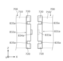
- FIG. 7 is a schematic plan view showing a pair of electrode bodies 700 to which covers 831a and 832a according to Modification 1 are attached.
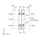
- FIG. 8 is a schematic plan view showing a state in which a pair of covers 831a and 832a according to Modification 1 are assembled.
- the electrode body 700 is indicated by dashed lines.
- the pair of covers 831 a and 832 a are cap-shaped, are attached to the ends of the electrode body 700 in the X-axis direction, and accommodate the tab portion 720 .
- Each of the covers 831a and 832a may or may not contain a cushioning material.
- a concave portion 833a is formed in the surface of one cover 831a facing the other cover 832a.
- the other cover 832a has a convex portion 834a that fits into the concave portion 833a on the surface facing the one cover 831a.
- the integrity between the pair of covers 831a and 832a is enhanced, and thus the integrity between the pair of electrode bodies 700 is enhanced.
- a pair of cutouts 835a are formed in the covers 831a and 832a to expose the joint position with the connection member 820 in the tab portion 720. As shown in FIG. Therefore, after the pair of electrode bodies 700 are integrated with the pair of covers 831a and 832a, the connection member 820 can be joined (welded) to the tab portion 720 through each notch 835a. As described above, since the pair of covers 831 a and 832 a enhances the integrity of the pair of electrode bodies 700 , the connection member 820 can be stably joined to the tab portion 720 .
- FIG. 9 is a schematic plan view showing a pair of electrode bodies 700b according to Modification 2. As shown in FIG. In FIG. 9, the outer shape of the container 100 is indicated by broken lines.
- the electrode body 700 in which the tab portion 720, which is the active material uncoated portion, is provided on a part of the main body portion 710 in the Z-axis direction is exemplified.
- Modification 2 illustrates an electrode body 700b in which active material uncoated portions (positive electrode active material uncoated portion 731b and negative electrode active material uncoated portion 732b) are provided over the entire Z-axis direction of main body portion 710b. and explain.
- a pair of electrode bodies 700b are arranged in the X-axis direction so that their winding axes L are aligned on the same straight line.
- Each electrode body 700b is arranged in the same space of the container 100 in such a posture that the positive electrode active material uncoated portion 731b faces the X-axis plus direction and the negative electrode active material uncoated portion 732b faces the X axis minus direction.
- a positive electrode connecting member 821b for electrically connecting the positive electrode active material uncoated portions 731b of the pair of electrode bodies 700b, and an electrically connecting member 821b electrically connecting the negative electrode active material uncoated portions 732b of the pair of electrode bodies 700b.
- a negative electrode connection member 822b that is electrically connected is accommodated.
- the positive electrode connection member 821b is formed in a shape that bypasses the body portion 710b of the electrode body 700b in the positive direction of the X axis, and is joined to the positive electrode current collector 610 (not shown in FIG. 9).
- the negative electrode connection member 822b is formed in a shape that circumvents the body portion 710b of the electrode body 700b in the negative direction of the X axis, and is joined to the negative electrode current collector 620 (not shown in FIG. 9). Between the pair of electrode bodies 700b, a plate-like cushioning material 810b is arranged between the positive electrode connecting member 821b and the negative electrode connecting member 822b. In this modified example as well, it is possible to reduce heat generation in the event of an abnormality while increasing the energy density.
- FIG. 10 is a schematic plan view showing a plurality of electrode bodies 700c according to Modification 3. As shown in FIG. In FIG. 10, the outer shape of the container 100c is indicated by broken lines. Also in this electrode body 700c, active material uncoated portions (positive electrode active material uncoated portion 731c and negative electrode active material uncoated portion 732c) are provided over the entire body portion 710c in the Z-axis direction.
- active material uncoated portions positive electrode active material uncoated portion 731c and negative electrode active material uncoated portion 732c
- the container 100c is a flat case that is long in the Z-axis direction and the length (thickness) in the Y-axis direction is shorter than the length in the X-axis direction.
- the pair of electrode bodies 700c are arranged in the Z-axis direction so that their winding axes L are parallel to the X-axis direction.
- Each electrode body 700c is arranged in the same space of the container 100c in such a posture that the positive electrode active material uncoated portion 731c faces the X axis plus direction and the negative electrode active material uncoated portion 732c faces the X axis minus direction.
- a positive electrode connecting member 821c electrically connecting the positive electrode active material uncoated portions 731c of the pair of electrode bodies 700c and a negative electrode active material uncoated portion 732c of the pair of electrode bodies 700c are electrically connected to each other.
- a negative electrode connection member 822c that is directly connected is accommodated.
- the positive electrode connection member 821c is joined to the positive electrode current collector 610 (not shown in FIG. 10), and the negative electrode connection member 822c is joined to the negative electrode current collector 620 (not shown in FIG. 10). Also in this modified example, it is possible to reduce heat generation in the event of an abnormality while increasing the energy density.
- Modification 4 In the above embodiment, the case where the positive electrode terminal 310 and the negative electrode terminal 320 are provided on each of the pair of short side surfaces 101 of the rectangular parallelepiped container 100 so as to face the X-axis direction is exemplified. However, the positive terminal 310 and the negative terminal 320 may be provided in a posture facing the Z-axis direction.
- Modification 4 exemplifies a case in which a notch is provided on each short side surface, and the positive electrode terminal 310 and the negative electrode terminal 320 facing in the Z-axis direction are arranged inside the notch. Even when such notches are provided, electrode terminals 300 (positive terminal 310 and negative terminal 320) are not limited to the present embodiment, and may be formed of bolts or the like.
- FIG. 11 is a schematic plan view showing the end portion of the power storage element 10D according to Modification 4 in the positive direction of the X axis. The same applies to the end portion of the power storage element 10D in the negative direction of the X axis.
- a container 100d of the storage element 10D has a pair of cutouts 190d formed at the ends in the positive direction of the X axis. Specifically, the pair of notches 190d are formed at the corners of both ends in the Z-axis direction of the container 100d.
- the pair of cutouts 190d are rectangular cutouts in plan view.
- One of the positive electrode terminal 310 and the negative electrode terminal 320 (the positive electrode terminal 310 in this modified example) is installed via an external gasket 400 on the bottom surface of the cutout portion 190d in the positive direction of the Z axis.
- the other of the positive terminal 310 and the negative terminal 320 (the negative terminal 320 in this modified example) is installed via an external gasket 400 on the top surface of the notch 190d in the negative direction of the Z axis.
- Modification 5 In the fourth modification, a pair of cutouts 190d are formed at both ends of the container 100d in the X-axis direction, and one electrode terminal (positive terminal 310 or negative terminal 320) is arranged in each cutout 190d. exemplified the case. In Modification 5, one notch is provided on each short side, and both positive terminal 310 and negative terminal 320 facing in the positive direction of the Z-axis are arranged inside the notch.
- FIG. 12 is a schematic plan view showing the end portion of the power storage element 10E according to Modification 5 in the positive direction of the X axis. The same applies to the end portion of the storage element 10E in the negative direction of the X axis.
- the container 100e of the storage element 10E has one notch 190e formed at the end in the positive direction of the X axis. Specifically, the notch 190e is formed at a corner of the container 100d in the positive Z-axis direction.
- the notch portion 190e is a rectangular notch in plan view. Both the positive electrode terminal 310 and the negative electrode terminal 320 are installed via the external gasket 400 on the bottom surface of the notch 190e.
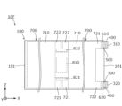
- FIG. 13 is a schematic cross-sectional view of a power storage element 10F according to Modification 6. As shown in FIG. As shown in FIG.
- the positive terminal 310 is provided at the end of the short side 101 of the container 100 in the positive direction of the X axis in the positive direction of the Z axis
- the negative terminal 320 is provided at the end of the positive direction of the X axis of the container 100. It is provided at the end in the negative direction of the Z axis of the short side surface 101 in the negative direction.
- tab portions a positive electrode tab portion and a negative electrode tab portion
- one electrode terminal (for example, the positive electrode terminal) may be provided at one end of the container in the X-axis direction, and the other electrode terminal (for example, the negative electrode terminal) may be provided at the other end of the container in the X-axis direction.
- the case where the pair of electrode bodies 700 are arranged in the same space inside the container 100 is exemplified.
- three or more electrode bodies may be arranged in the same space.
- the cushioning material 810 is provided between the pair of electrode bodies 700 is exemplified, but the cushioning material may not be provided.
- the tab portion 720 has a bent portion and a pair of extending portions, but the tab portion may not have a bent portion. In this case, the tab portion is flat as a whole.
- both ends of the plurality of protruding pieces 743 forming the pair of extending portions 724 of the positive electrode tab portion 721 are arranged gradually toward the outer circumference from the innermost protruding piece 743 .
- An example is shown.
- the positions of both ends of the plurality of protruding pieces forming each extending portion are arbitrary.
- both ends of the plurality of protruding pieces forming each extension may be flush with each other.
- the positive electrode tab portion 721 and the negative electrode tab portion 722 are reversed (upside down) when viewed in the X-axis direction between one end surface and the other end surface of the main body portion 710 of the electrode body 700 . Although the case where it is reversed was illustrated, it does not need to be reversed.
- the wound electrode body 700 is exemplified.
- the shape of the electrode body is not limited to the wound type, and may be a stack type in which flat plates are stacked, or a shape in which the electrode plates and/or separators are folded in a bellows shape (a separator is folded in a bellows shape to form a rectangular electrode plate). may be sandwiched between them, or a configuration in which the electrode plate and the separator are stacked and then folded in a bellows shape, etc.).
- the stacking direction of the electrode body may be the thickness direction of the container. Even in such an unwound laminated electrode assembly, if one electrode assembly is long, it is difficult to stack the electrode plates and separators with high accuracy.
- each laminated electrode body can be easily manufactured.
- the present invention can be applied to power storage elements such as lithium ion secondary batteries.
- Electrode bodies 100, 100c, 100d, 100e Container 110 Container body 120 Lid 300 Electrode terminal 600 Current collectors 700, 700b, 700c Electrode bodies 710, 710b, 710c Body part 711 Curved part 712 Flat part 720 Tab part 721 Positive electrode tab part 722 Negative electrode tab part 723 Bending part 724 Extension part 731b, 731c Positive electrode active material uncoated part 732b, 732c Negative electrode active material uncoated part 740 Positive electrode plate 750 Negative electrode plate 810, 810b Cushioning material 820 Connection Members 821, 821b, 821c Positive electrode connecting members 822, 822b, 822c Negative electrode connecting members 830, 831a, 832a Cover L Winding shaft
Landscapes
- Chemical & Material Sciences (AREA)
- Chemical Kinetics & Catalysis (AREA)
- Electrochemistry (AREA)
- General Chemical & Material Sciences (AREA)
- Engineering & Computer Science (AREA)
- Power Engineering (AREA)
- Microelectronics & Electronic Packaging (AREA)
- Manufacturing & Machinery (AREA)
- Connection Of Batteries Or Terminals (AREA)
Priority Applications (1)
| Application Number | Priority Date | Filing Date | Title |
|---|---|---|---|
| JP2023566158A JPWO2023105987A1 (https=) | 2021-12-09 | 2022-10-31 |
Applications Claiming Priority (2)
| Application Number | Priority Date | Filing Date | Title |
|---|---|---|---|
| JP2021-200352 | 2021-12-09 | ||
| JP2021200352 | 2021-12-09 |
Publications (1)
| Publication Number | Publication Date |
|---|---|
| WO2023105987A1 true WO2023105987A1 (ja) | 2023-06-15 |
Family
ID=86730193
Family Applications (1)
| Application Number | Title | Priority Date | Filing Date |
|---|---|---|---|
| PCT/JP2022/040588 Ceased WO2023105987A1 (ja) | 2021-12-09 | 2022-10-31 | 蓄電素子 |
Country Status (2)
| Country | Link |
|---|---|
| JP (1) | JPWO2023105987A1 (https=) |
| WO (1) | WO2023105987A1 (https=) |
Citations (7)
| Publication number | Priority date | Publication date | Assignee | Title |
|---|---|---|---|---|
| JP2003178796A (ja) * | 2001-10-01 | 2003-06-27 | Matsushita Electric Ind Co Ltd | 密閉型アルカリ蓄電池 |
| JP2011060767A (ja) * | 2009-09-10 | 2011-03-24 | Samsung Sdi Co Ltd | 二次電池 |
| JP2012227110A (ja) * | 2010-06-21 | 2012-11-15 | Toshiba Corp | 電池 |
| JP2013168253A (ja) * | 2012-02-14 | 2013-08-29 | Hitachi Maxell Ltd | 巻回型電池 |
| US20150010805A1 (en) * | 2013-07-02 | 2015-01-08 | Samsung Sdi Co., Ltd. | Rechargeable battery |
| US20150194657A1 (en) * | 2014-01-09 | 2015-07-09 | Samsung Sdi Co., Ltd. | Secondary battery |
| JP2022050804A (ja) * | 2020-09-18 | 2022-03-31 | プライムプラネットエナジー&ソリューションズ株式会社 | 二次電池 |
-
2022
- 2022-10-31 JP JP2023566158A patent/JPWO2023105987A1/ja active Pending
- 2022-10-31 WO PCT/JP2022/040588 patent/WO2023105987A1/ja not_active Ceased
Patent Citations (7)
| Publication number | Priority date | Publication date | Assignee | Title |
|---|---|---|---|---|
| JP2003178796A (ja) * | 2001-10-01 | 2003-06-27 | Matsushita Electric Ind Co Ltd | 密閉型アルカリ蓄電池 |
| JP2011060767A (ja) * | 2009-09-10 | 2011-03-24 | Samsung Sdi Co Ltd | 二次電池 |
| JP2012227110A (ja) * | 2010-06-21 | 2012-11-15 | Toshiba Corp | 電池 |
| JP2013168253A (ja) * | 2012-02-14 | 2013-08-29 | Hitachi Maxell Ltd | 巻回型電池 |
| US20150010805A1 (en) * | 2013-07-02 | 2015-01-08 | Samsung Sdi Co., Ltd. | Rechargeable battery |
| US20150194657A1 (en) * | 2014-01-09 | 2015-07-09 | Samsung Sdi Co., Ltd. | Secondary battery |
| JP2022050804A (ja) * | 2020-09-18 | 2022-03-31 | プライムプラネットエナジー&ソリューションズ株式会社 | 二次電池 |
Also Published As
| Publication number | Publication date |
|---|---|
| JPWO2023105987A1 (https=) | 2023-06-15 |
Similar Documents
| Publication | Publication Date | Title |
|---|---|---|
| WO2023063332A1 (ja) | 蓄電素子 | |
| WO2023063328A1 (ja) | 蓄電素子 | |
| JP7322872B2 (ja) | 蓄電素子 | |
| JP2026049037A (ja) | 蓄電素子 | |
| JP7793891B2 (ja) | 蓄電素子 | |
| US20240429503A1 (en) | Energy storage device | |
| JP7749920B2 (ja) | 蓄電素子 | |
| US20250329890A1 (en) | Energy storage device | |
| US20240097179A1 (en) | Energy storage device | |
| US20240154179A1 (en) | Energy storage device | |
| JP7676790B2 (ja) | 蓄電素子 | |
| JP7318333B2 (ja) | 蓄電素子 | |
| WO2023105987A1 (ja) | 蓄電素子 | |
| JP2023136602A (ja) | 蓄電装置 | |
| JP2023090507A (ja) | 蓄電装置 | |
| US20260100456A1 (en) | Electricity storage device | |
| WO2024150803A1 (ja) | 蓄電素子及びその製造方法 | |
| JP2024100044A (ja) | 蓄電素子 | |
| WO2025089164A1 (ja) | 蓄電素子および蓄電装置 | |
| WO2025249207A1 (ja) | 蓄電素子及び蓄電装置 | |
| WO2024150804A1 (ja) | 蓄電素子 | |
| WO2026063398A1 (ja) | 蓄電素子 | |
| JP2022116686A (ja) | 蓄電素子及びその製造方法 | |
| JP2023054569A (ja) | 蓄電素子 | |
| JP2025128615A (ja) | 蓄電素子 |
Legal Events
| Date | Code | Title | Description |
|---|---|---|---|
| 121 | Ep: the epo has been informed by wipo that ep was designated in this application |
Ref document number: 22903919 Country of ref document: EP Kind code of ref document: A1 |
|
| WWE | Wipo information: entry into national phase |
Ref document number: 2023566158 Country of ref document: JP |
|
| NENP | Non-entry into the national phase |
Ref country code: DE |
|
| 122 | Ep: pct application non-entry in european phase |
Ref document number: 22903919 Country of ref document: EP Kind code of ref document: A1 |