WO2023105709A1 - セメント焼成装置 - Google Patents
セメント焼成装置 Download PDFInfo
- Publication number
- WO2023105709A1 WO2023105709A1 PCT/JP2021/045324 JP2021045324W WO2023105709A1 WO 2023105709 A1 WO2023105709 A1 WO 2023105709A1 JP 2021045324 W JP2021045324 W JP 2021045324W WO 2023105709 A1 WO2023105709 A1 WO 2023105709A1
- Authority
- WO
- WIPO (PCT)
- Prior art keywords
- mixing chamber
- cement
- rotary kiln
- exhaust gas
- clinker cooler
- Prior art date
Links
Images


Classifications
-
- C—CHEMISTRY; METALLURGY
- C04—CEMENTS; CONCRETE; ARTIFICIAL STONE; CERAMICS; REFRACTORIES
- C04B—LIME, MAGNESIA; SLAG; CEMENTS; COMPOSITIONS THEREOF, e.g. MORTARS, CONCRETE OR LIKE BUILDING MATERIALS; ARTIFICIAL STONE; CERAMICS; REFRACTORIES; TREATMENT OF NATURAL STONE
- C04B7/00—Hydraulic cements
- C04B7/36—Manufacture of hydraulic cements in general
- C04B7/43—Heat treatment, e.g. precalcining, burning, melting; Cooling
- C04B7/44—Burning; Melting
Definitions
- the present invention reduces the concentration of nitrogen oxides (hereinafter referred to as "NOx”) in combustion gas discharged from a cement calcining apparatus having an RSP calciner (hereinafter referred to as "RSP cement calcining apparatus"). Regarding technology.
- NOx nitrogen oxides
- the exhaust gas of the cement kiln contains NOx resulting from the high temperature range of the calcination zone, and the NOx concentration is high.
- the NO concentration is reduced by adding a denitration agent such as urea or ammonia, or reducing by combustion in the calciner.
- a general RSP type cement burning apparatus 21 includes a rotary kiln 22, an air current type and vortex type calcining furnace 23, a mixing chamber 24, a loop duct 25, a clinker cooler 26, and the like.
- primary air A1 is blown into the rotary kiln 22 from the kiln burner 22a of the rotary kiln 22
- secondary air A2a is blown into the rotary kiln 22 from the clinker cooler 26 via the kiln burner 22a
- secondary air A2b is blown from the clinker cooler 26 into the rotary kiln 22.
- an object of the present invention is to more effectively denitrify cement kiln exhaust gas in an RSP type cement calcining apparatus.
- the present invention provides a cement firing apparatus comprising a rotary kiln, a mixing chamber disposed between the rotary kiln and the lowest cyclone, and a preheater cyclone positioned second from the bottom on the mixing chamber. and a clinker cooler for cooling the cement clinker discharged from the rotary kiln, and introducing the exhaust gas from the clinker cooler directly into the furnace of the calciner. and a gas duct leading to a region after the outlet of the mixing chamber.
- the exhaust gas from the clinker cooler is not introduced directly into the furnace of the calcining furnace, but is introduced into the region after the outlet of the mixing chamber, thereby allowing the outlet of the mixing chamber to pass from the kiln bottom of the rotary kiln. It is possible to form a wide denitrification area containing the cement, and to reduce NOx by about 100 ppm compared to the conventional cement calciner.
- the above cement burning apparatus may include a gas duct that branches from the gas duct and guides the exhaust gas from the clinker cooler to the burner installed in the calciner.
- the denitration effect can be further enhanced.
- the present invention is a method of operating a cement burning apparatus, comprising a rotary kiln, a mixing chamber disposed between the rotary kiln and the lowest cyclone, and a preheater cyclone on the second stage from the bottom of the mixing chamber.
- a cement calcining apparatus comprising an air flow type and vortex type calcining furnace disposed between them and a clinker cooler for cooling cement clinker discharged from the rotary kiln, wherein the exhaust gas from the clinker cooler is discharged into the calcining furnace. It is characterized in that it is not introduced directly into the interior of the mixing chamber, but is introduced into a region after the outlet of the mixing chamber.
- the present invention it is possible to form a wide denitrification area including the outlet of the mixing chamber from the kiln bottom of the rotary kiln, and reduce NOx by about 100 ppm compared to the conventional method.
- 90% or more of the exhaust gas from the clinker cooler can be introduced into the area after the outlet of the mixing chamber.
- 10% or less of the exhaust gas from the clinker cooler can be introduced into the burner installed in the calciner.
- the denitrification effect is enhanced, and the decarbonation efficiency of the cement raw material can also be improved.
- the cement kiln exhaust gas can be denitrified more effectively in the RSP type cement calcining apparatus.
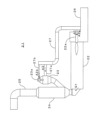
- FIG. 1 is an overall configuration diagram showing an embodiment of a cement burning apparatus according to the present invention
- FIG. It is a schematic diagram showing the main part of a conventional RSP type cement burning apparatus. It is a diagram. It is an explanatory diagram of a NOx reduction method in a conventional RSP type cement burning apparatus.
- FIG. 1 shows an embodiment of a cement firing apparatus according to the present invention, comprising a rotary kiln 2, a mixing chamber 4 connected to the kiln bottom 2b of the rotary kiln 2, and a lowermost cyclone located above the mixing chamber 4. (not shown), a preheater cyclone in the second stage from the bottom (not shown, hereinafter referred to as "two-stage cyclone"), and an air flow type and vortex flow type temporary
- an RSP type cement burning apparatus 1 equipped with a furnace 3 and a clinker cooler 6 for cooling cement clinker discharged from a rotary kiln 2
- exhaust gas G2 from the clinker cooler 6 is sent to the kiln burner 2a and the outlet 4b of the mixing chamber 4.
- the gas duct 7 is branched into a gas duct 7a leading to the area after the outlet 4b of the mixing chamber 4 and a gas duct 7b leading to the calcining furnace burner 3a installed in the calcining furnace 3 .
- a denitration burner 8 (8A, 8B) may be provided between the kiln bottom 2b of the rotary kiln 2 and the inlet 4a of the mixing chamber 4.
- the gas duct 27a installed in the conventional cement burning apparatus 21 shown in FIG. 2 does not exist in the cement burning apparatus 1 according to the present invention.
- Fuel such as pulverized coal, primary air A1, and secondary air A2a from the clinker cooler 6 are blown into the kiln burner 2a of the rotary kiln 2, and the combustion gas G1 and the like of the rotary kiln 2 are used in the preheater disposed after the loop duct 5. to preheat the cement raw material.
- the exhaust gas G2 from the clinker cooler 6 is directed through the gas duct 7 to the burner 3a installed in the calcining furnace 3 and the area after the outlet 4b of the mixing chamber 4 (the inlet of the loop duct 5 in this embodiment). lead.
- the fuel such as pulverized coal supplied from the burner 3a in the calcining furnace 3 is partially burned using a part (A2b) of the exhaust gas G2, and gasified by the high temperature preheated raw material R supplied to the calcining furnace 3,
- the tar or the like is introduced into the mixing chamber 4 while being prevented by the preheated raw material R from adhering to the wall surface of the calcining furnace 3 .
- This reduces NOx in the exhaust gas G1 of the rotary kiln 2 inside the mixing chamber 4 .
- the exhaust gas from which NOx has been reduced is completely combusted by the tertiary air A3 in the loop duct 5, and then introduced into the subsequent preheater as the exhaust gas G3.
- the exhaust gas G2 from the clinker cooler 6 is used as the partial combustion air A2b in the calcining furnace burner 3a and the tertiary air A3 to the mixing chamber 4 after the outlet 4b.
- the exhaust gas G2 may not be used as the partial combustion air A2b in the furnace burner 3a, and the exhaust gas G2 may be used only as the tertiary air A3.
- all the exhaust gas G2 from the clinker cooler 6 that has been introduced directly into the calcining furnace 3 is mixed. It is introduced into the region of the chamber 4 after the outlet 4b.
Landscapes
- Chemical & Material Sciences (AREA)
- Engineering & Computer Science (AREA)
- Ceramic Engineering (AREA)
- Physics & Mathematics (AREA)
- Thermal Sciences (AREA)
- Materials Engineering (AREA)
- Structural Engineering (AREA)
- Organic Chemistry (AREA)
- Curing Cements, Concrete, And Artificial Stone (AREA)
- Waste-Gas Treatment And Other Accessory Devices For Furnaces (AREA)
- Treating Waste Gases (AREA)
- Furnace Details (AREA)
Abstract
【課題】RSP式セメント焼成装置においてセメントキルン排ガスの脱硝をより効果的に行う。 【解決手段】ロータリーキルン2と、ロータリーキルンと最下段サイクロンとの間に配置される混合室4と、混合室と下から2段目のプレヒータサイクロンとの間に配置される気流式及び渦流式の仮焼炉3と、ロータリーキルンから排出されたセメントクリンカを冷却するクリンカクーラ6と、クリンカクーラからの排ガスG2を仮焼炉の炉内に直接導入するガスダクトを備えず、混合室の出口部以降の領域に導入するガスダクト7aとを備えるセメント焼成装置1。ガスダクト7から分岐し、クリンカクーラからの排ガスを仮焼炉に設置されたバーナー3aに導くガスダクト7bを設けてもよく、ロータリーキルンの窯尻2bと混合室の入口部4aとの間に脱硝用バーナー8(8A、8B)を設けてもよい。
Description
本発明は、RSP式仮焼炉を有するセメント焼成装置(以下「RSP式セメント焼成装置」という。)から排出される燃焼ガス中の窒素酸化物(以下「NOx」という。)の濃度を低減する技術に関する。
仮焼炉を有するNSP型セメント焼成装置には種々の型式が存在するが、いずれの型式のものでも、セメントキルンの排ガスには焼成帯の高温域に起因するNOxが含まれ、NOx濃度が高い場合には、尿素やアンモニア等の脱硝剤を投入したり、仮焼炉における燃焼による還元作用等によってNO濃度を低減している。
NSP型セメント焼成装置の一種であるRSP(商品名、川崎重工業株式会社、太平洋セメント株式会社製)式セメント焼成装置においても、セメント焼成装置の排ガス中のNOxを低減するため、種々の方策が取り入れられている。
図2に示すように、一般的なRSP式セメント焼成装置21は、ロータリーキルン22と、気流式及び渦流式の仮焼炉23と、混合室24と、ループダクト25と、クリンカクーラ26等を備え、ロータリーキルン22のキルンバーナー22aから1次空気A1がロータリーキルン22内に吹き込まれ、クリンカクーラ26から2次空気A2aがキルンバーナー22aを介してロータリーキルン22内に吹き込まれ、クリンカクーラ26から2次空気A2bがガスダクト27、27bを介して仮焼炉バーナー23aから仮焼炉23内に吹き込まれ、クリンカクーラ26からの3次空気A3がガスダクト27、27aを介して仮焼炉23の炉内に導入される。
上記構成を有するセメント焼成装置21において、セメント焼成装置21の排ガスG1中のNOを低減するため、例えば図3に示すように、3次空気A3(図2参照)の一部A3b(3次空気A3の80%程度)を仮焼炉23に導入せずに混合室24の出口部24b以降に供給したり、ロータリーキルン22の窯尻22bから混合室24の入口部24aとの間に脱硝用バーナー28(28A、28B)を設置してセメントキルン排ガスの脱硝が行われている。
しかし、上記3次空気A3の一部A3bを混合室24の出口部24b以降にバイパスさせる方法では、セメントキルン排ガスのNOx低減効果が小さく、脱硝用バーナーを設置した場合でも70ppm程度に留まっている。
そこで、本発明は、上記の点に鑑みてなされたものであって、RSP式セメント焼成装置においてセメントキルン排ガスの脱硝をより効果的に行うことを目的とする。
上記目的を達成するため、本発明は、セメント焼成装置であって、ロータリーキルンと、該ロータリーキルンと最下段サイクロンとの間に配置される混合室と、該混合室と下から2段目のプレヒータサイクロンとの間に配置される気流式及び渦流式の仮焼炉と、前記ロータリーキルンから排出されたセメントクリンカを冷却するクリンカクーラと、該クリンカクーラからの排ガスを前記仮焼炉の炉内に直接導入するガスダクトを備えず、前記混合室の出口部以降の領域に導入するガスダクトとを備えることを特徴とする。
本発明によれば、クリンカクーラからの排ガスを仮焼炉の炉内に直接導入せずに、混合室の出口部以降の領域に導入することで、ロータリーキルンの窯尻から混合室の出口部を含む広い脱硝領域を形成することができ、従来のセメント焼成装置よりも100ppm程度NOxを低減することができる。
上記セメント焼成装置において、前記ガスダクトから分岐し、前記クリンカクーラからの排ガスを前記仮焼炉に設置されたバーナーに導くガスダクトを備えることができる。
また、前記ロータリーキルンの窯尻と前記混合室の入口部との間に脱硝用バーナーを設けることで、さらに脱硝効果を高めることができる。
さらに、本発明は、セメント焼成装置の運転方法であって、ロータリーキルンと、該ロータリーキルンと最下段サイクロンとの間に配置される混合室と、該混合室と下から2段目のプレヒータサイクロンとの間に配置される気流式及び渦流式の仮焼炉と、前記ロータリーキルンから排出されたセメントクリンカを冷却するクリンカクーラとを備えるセメント焼成装置において、前記クリンカクーラからの排ガスを前記仮焼炉の炉内に直接導入せずに、前記混合室の出口部以降の領域に導入することを特徴とする。
本発明によれば、ロータリーキルンの窯尻から混合室の出口部を含む広い脱硝領域を形成し、従来よりも100ppm程度NOxを低減することができる。
上記セメント焼成装置の運転方法において、前記混合室の出口部以降の領域にクリンカクーラからの排ガスの90%以上を導入することができる。
また、前記クリンカクーラからの排ガスの10%以下を前記仮焼炉に設置されたバーナーに導入することができる。
さらに、前記ロータリーキルンの窯尻と前記混合室の入口部との間に燃料を吹き込み、該燃料を酸素濃度が低い領域にてガス化させることで、脱硝効果を高めると共に、セメント原料の脱炭酸効率も向上させることができる。
以上のように、本発明によれば、RSP式セメント焼成装置においてセメントキルン排ガスの脱硝をより効果的に行うことができる。
次に、本発明を実施するための形態について、図面を参照しながら詳細に説明する。
図1は、本発明に係るセメント焼成装置の一実施の形態を示し、ロータリーキルン2と、ロータリーキルン2の窯尻2bに接続される混合室4と、混合室4の上方に位置し、最下段サイクロン(不図示)に通じるループダクト5と、下から2段目のプレヒータサイクロン(不図示、以下「2段サイクロン」という。)と混合室4との間に配置される気流式及び渦流式の仮焼炉3と、ロータリーキルン2から排出されたセメントクリンカを冷却するクリンカクーラ6等を備えるRSP式セメント焼成装置1において、クリンカクーラ6からの排ガスG2をキルンバーナー2aと、混合室4の出口部4b以降の領域と、仮焼炉バーナー3aとに導くガスダクト7を備えることを特徴とする。ガスダクト7は、混合室4の出口部4b以降の領域へのガスダクト7aと、仮焼炉3に設置された仮焼炉バーナー3aへのガスダクト7bに分岐する。また、ロータリーキルン2の窯尻2bと混合室4の入口部4aとの間に脱硝用バーナー8(8A、8B)を設けてもよい。尚、本発明に係るセメント焼成装置1には、図2に示した従来のセメント焼成装置21に設置されていたガスダクト27aは存在しない。
次に、上記構成を有するセメント焼成装置1の動作について説明する。
ロータリーキルン2のキルンバーナー2aに微粉炭等の燃料、1次空気A1及びクリンカクーラ6からの2次空気A2aを吹き込み、ループダクト5以降に配置されたプレヒータにおいて、ロータリーキルン2の燃焼ガスG1等を用いてセメント原料の予熱を行う。一方、クリンカクーラ6からの排ガスG2をガスダクト7を介して仮焼炉3に設置されたバーナー3aと、混合室4の出口部4b以降の領域(本実施例ではループダクト5の入口部)に導く。すなわち、クリンカクーラ6からの排ガスG2を従来のように仮焼炉3の炉内に直接導入せずに、バーナー3aでの2次空気A2bと、混合室4の出口部4b以降への3次空気A3として用いる。また、2段サイクロンからの予熱原料Rはすべて仮焼炉3に導入する。
仮焼炉3でバーナー3aから供給された微粉炭等の燃料を排ガスG2の一部(A2b)を用いて部分燃焼させると共に、仮焼炉3に供給された高温の予熱原料Rによってガス化し、タール等が仮焼炉3の壁面へ付着することを予熱原料Rによって防止しながら混合室4に導入する。これによって、混合室4の内部でロータリーキルン2の排ガスG1中のNOxを還元する。NOxを還元した後の排ガスは、ループダクト5において3次空気A3によって完全燃焼した後、後段のプレヒータに排ガスG3として導入される。
また、ロータリーキルン2の窯尻2bと混合室4の入口部4aとの間に脱硝用バーナー8(8A、8B)から燃料を吹き込み、ガスの混合を促進すると共に、ロータリーキルン2の排ガスG1中のNOxを混合室4の低酸素領域において還元する。さらに、仮焼炉3で燃料の一部を燃焼させることでセメント原料の脱炭酸効率も向上させることができる。
上記構成を有するセメント焼成装置1によれば、図1に示すように、ロータリーキルン2の窯尻2bから混合室4の出口部4bを含む広い脱硝領域DZを形成することができ、図2に示した従来のセメント焼成装置21よりも100ppm程度NOxを低減することができる。
尚、上記実施の形態においては、クリンカクーラ6からの排ガスG2を仮焼炉バーナー3aでの部分燃焼空気A2bと、混合室4の出口部4b以降への3次空気A3として用いたが、仮焼炉バーナー3aでの部分燃焼空気A2bに排ガスG2を用いず、排ガスG2を3次空気A3にのみ用いてもよい。本発明は、排ガスG2を2次空気A2a及び仮焼炉バーナー3aに用いるか否かを問わず、従来仮焼炉3の炉内に直接導入していたクリンカクーラ6からの排ガスG2をすべて混合室4の出口部4b以降の領域に導入するものである。
1 (RSP式)セメント焼成装置
2 ロータリーキルン
3 仮焼炉
4 混合室
5 ループダクト
6 クリンカクーラ
7 ガスダクト
8(8A、8B) 脱硝用バーナー
2 ロータリーキルン
3 仮焼炉
4 混合室
5 ループダクト
6 クリンカクーラ
7 ガスダクト
8(8A、8B) 脱硝用バーナー
Claims (7)
- ロータリーキルンと、
該ロータリーキルンと最下段サイクロンとの間に配置される混合室と、
該混合室と下から2段目のプレヒータサイクロンとの間に配置される気流式及び渦流式の仮焼炉と、
前記ロータリーキルンから排出されたセメントクリンカを冷却するクリンカクーラと、
該クリンカクーラからの排ガスを前記仮焼炉の炉内に直接導入するガスダクトを備えず、前記混合室の出口部以降の領域に導入するガスダクトとを備えることを特徴とするセメント焼成装置。 - 前記ガスダクトから分岐し、前記クリンカクーラからの排ガスを前記仮焼炉に設置されたバーナーに導くガスダクトを備えることを特徴とする請求項1に記載のセメント焼成装置。
- 前記ロータリーキルンの窯尻と前記混合室の入口部との間に脱硝用バーナーを備えることを特徴とする請求項1又は2に記載のセメント焼成装置。
- ロータリーキルンと、該ロータリーキルンと最下段サイクロンとの間に配置される混合室と、該混合室と下から2段目のプレヒータサイクロンとの間に配置される気流式及び渦流式の仮焼炉と、前記ロータリーキルンから排出されたセメントクリンカを冷却するクリンカクーラとを備えるセメント焼成装置において、
前記クリンカクーラからの排ガスを前記仮焼炉の炉内に直接導入せずに、前記混合室の出口部以降の領域に導入することを特徴とするセメント焼成装置の運転方法。 - 前記混合室の出口部以降の領域にクリンカクーラからの排ガスの90%以上を導入することを特徴とする請求項4に記載のセメント焼成装置の運転方法。
- 前記クリンカクーラからの排ガスの10%以下を前記仮焼炉に設置されたバーナーに導入することを特徴とする請求項4又は5に記載のセメント焼成装置の運転方法。
- 前記ロータリーキルンの窯尻と前記混合室の入口部との間に燃料を吹き込み、該燃料を酸素濃度が低い領域にてガス化させ、前記ロータリーキルンの排ガス中のNOxの還元を行うことを特徴とする請求項4、5又は6に記載のセメント焼成装置の運転方法。
Priority Applications (2)
| Application Number | Priority Date | Filing Date | Title |
|---|---|---|---|
| PCT/JP2021/045324 WO2023105709A1 (ja) | 2021-12-09 | 2021-12-09 | セメント焼成装置 |
| TW111104767A TW202323745A (zh) | 2021-12-09 | 2022-02-09 | 水泥燒成裝置 |
Applications Claiming Priority (1)
| Application Number | Priority Date | Filing Date | Title |
|---|---|---|---|
| PCT/JP2021/045324 WO2023105709A1 (ja) | 2021-12-09 | 2021-12-09 | セメント焼成装置 |
Publications (1)
| Publication Number | Publication Date |
|---|---|
| WO2023105709A1 true WO2023105709A1 (ja) | 2023-06-15 |
Family
ID=86730023
Family Applications (1)
| Application Number | Title | Priority Date | Filing Date |
|---|---|---|---|
| PCT/JP2021/045324 WO2023105709A1 (ja) | 2021-12-09 | 2021-12-09 | セメント焼成装置 |
Country Status (2)
| Country | Link |
|---|---|
| TW (1) | TW202323745A (ja) |
| WO (1) | WO2023105709A1 (ja) |
Citations (4)
| Publication number | Priority date | Publication date | Assignee | Title |
|---|---|---|---|---|
| JPS62112986A (ja) * | 1985-11-11 | 1987-05-23 | 株式会社神戸製鋼所 | 仮焼炉付原料粉末予熱装置 |
| JPH11268936A (ja) * | 1998-03-23 | 1999-10-05 | Taiheiyo Cement Corp | セメントの製造方法 |
| JP2011201717A (ja) * | 2010-03-25 | 2011-10-13 | Taiheiyo Cement Corp | セメント焼成設備の燃焼排ガス中のNOx低減方法 |
| JP2014033997A (ja) * | 2012-08-08 | 2014-02-24 | Kawasaki Heavy Ind Ltd | 汚泥の処理設備および処理方法 |
-
2021
- 2021-12-09 WO PCT/JP2021/045324 patent/WO2023105709A1/ja unknown
-
2022
- 2022-02-09 TW TW111104767A patent/TW202323745A/zh unknown
Patent Citations (4)
| Publication number | Priority date | Publication date | Assignee | Title |
|---|---|---|---|---|
| JPS62112986A (ja) * | 1985-11-11 | 1987-05-23 | 株式会社神戸製鋼所 | 仮焼炉付原料粉末予熱装置 |
| JPH11268936A (ja) * | 1998-03-23 | 1999-10-05 | Taiheiyo Cement Corp | セメントの製造方法 |
| JP2011201717A (ja) * | 2010-03-25 | 2011-10-13 | Taiheiyo Cement Corp | セメント焼成設備の燃焼排ガス中のNOx低減方法 |
| JP2014033997A (ja) * | 2012-08-08 | 2014-02-24 | Kawasaki Heavy Ind Ltd | 汚泥の処理設備および処理方法 |
Also Published As
| Publication number | Publication date |
|---|---|
| TW202323745A (zh) | 2023-06-16 |
Similar Documents
| Publication | Publication Date | Title |
|---|---|---|
| CA2445818C (en) | Method and system for process gas entrainment and mixing in a kiln system | |
| KR100760074B1 (ko) | 시멘트 크링커 제조 설비 및 방법 | |
| JP7212582B2 (ja) | セメント焼成装置及びセメントキルン排ガスの脱硝方法 | |
| US20090130615A1 (en) | Method for Calcination of a Material with Low NOchi Emissions | |
| CN113465366A (zh) | 一种回转窑低氮燃烧装置及生产方法 | |
| AU2001269389A1 (en) | Method and plant for manufacturing cement clinker | |
| CN106029599A (zh) | 水泥烧成装置及水泥窑排气的脱硝方法 | |
| MXPA04008616A (es) | Metodo y planta para fabricar clinker de cemento. | |
| WO2023105709A1 (ja) | セメント焼成装置 | |
| JP7202467B2 (ja) | セメントキルン排ガスの脱硝方法 | |
| JPWO2021019753A5 (ja) | セメントキルン排ガスの脱硝方法 | |
| JPS5839790B2 (ja) | セメントクリンカの焼成装置 | |
| ES2260049T5 (es) | Procedimiento e instalacion para el tratamiento termico de material de grano fino. | |
| WO2021085668A1 (ko) | 실시간 분석 및 저 nox 연소와 후처리 기술을 적용한 nox가 저감된 시멘트 제조 장치 및 방법 | |
| JP2002173349A (ja) | セメント原料の焼成方法および焼成装置 | |
| JP2001335347A (ja) | セメント原料の仮焼装置 | |
| WO2023145046A1 (ja) | セメント焼成装置及びセメントキルン排ガスの脱硝方法 | |
| JP3250758B2 (ja) | セメントクリンカの焼成装置 | |
| JPH0146466B2 (ja) | ||
| JPH0347133B2 (ja) | ||
| TW202106370A (zh) | 水泥燒成裝置及水泥窯排氣之脫硝方法 | |
| RU2076291C1 (ru) | Устройство для тепловой обработки порошкообразного материала | |
| JPS5945625B2 (ja) | 粉末原料予熱装置の燃焼用空気吹込装置 | |
| JPH0152339B2 (ja) | ||
| JPS59128237A (ja) | セメント原料又は石灰石類の仮焼方法および仮焼炉 |
Legal Events
| Date | Code | Title | Description |
|---|---|---|---|
| 121 | Ep: the epo has been informed by wipo that ep was designated in this application |
Ref document number: 21967205 Country of ref document: EP Kind code of ref document: A1 |