WO2023100734A1 - 画像形成システム、画像形成方法、及びプログラム - Google Patents
画像形成システム、画像形成方法、及びプログラム Download PDFInfo
- Publication number
- WO2023100734A1 WO2023100734A1 PCT/JP2022/043318 JP2022043318W WO2023100734A1 WO 2023100734 A1 WO2023100734 A1 WO 2023100734A1 JP 2022043318 W JP2022043318 W JP 2022043318W WO 2023100734 A1 WO2023100734 A1 WO 2023100734A1
- Authority
- WO
- WIPO (PCT)
- Prior art keywords
- illumination
- light
- image
- dimensional
- illumination pattern
- Prior art date
- Legal status (The legal status is an assumption and is not a legal conclusion. Google has not performed a legal analysis and makes no representation as to the accuracy of the status listed.)
- Ceased
Links
Images









Classifications
-
- G—PHYSICS
- G01—MEASURING; TESTING
- G01N—INVESTIGATING OR ANALYSING MATERIALS BY DETERMINING THEIR CHEMICAL OR PHYSICAL PROPERTIES
- G01N21/00—Investigating or analysing materials by the use of optical means, i.e. using sub-millimetre waves, infrared, visible or ultraviolet light
- G01N21/84—Systems specially adapted for particular applications
- G01N21/88—Investigating the presence of flaws or contamination
-
- G—PHYSICS
- G06—COMPUTING OR CALCULATING; COUNTING
- G06T—IMAGE DATA PROCESSING OR GENERATION, IN GENERAL
- G06T1/00—General purpose image data processing
-
- G—PHYSICS
- G06—COMPUTING OR CALCULATING; COUNTING
- G06T—IMAGE DATA PROCESSING OR GENERATION, IN GENERAL
- G06T5/00—Image enhancement or restoration
- G06T5/50—Image enhancement or restoration using two or more images, e.g. averaging or subtraction
-
- H—ELECTRICITY
- H04—ELECTRIC COMMUNICATION TECHNIQUE
- H04N—PICTORIAL COMMUNICATION, e.g. TELEVISION
- H04N23/00—Cameras or camera modules comprising electronic image sensors; Control thereof
- H04N23/56—Cameras or camera modules comprising electronic image sensors; Control thereof provided with illuminating means
Definitions
- the present invention relates to an image forming system, an image forming method, and a program.
- a single-element detector such as a photodiode or a PMT (photomultiplier tube) may be used in visual inspection of an object.
- a technique called SPI single pixel imaging
- the object is irradiated with different illumination patterns multiple times, the scattered light intensity at that time is acquired with a single-element detector, and the primary measurement is performed based on the signal intensity of the detector for the illumination pattern It is a technique of reconstructing a 1D or 2D image.
- the object of the present invention is to achieve the one-dimensional or two-dimensional image acquisition of a moving object or the one-dimensional or two-dimensional image acquisition of a moving object with a single-element detector. That is.
- the image forming system of the present invention includes: an illumination projection unit that irradiates light of a plurality of illumination patterns onto an object to be measured that moves at a substantially constant speed; a detection unit that detects the light intensity of light reflected from the measurement object by the light of the illumination pattern; an illumination control unit that sequentially switches the illumination pattern from among the plurality of illumination patterns and irradiates light from the illumination projection unit; a generation unit that generates a reconstructed image that is two-dimensionally reconstructed from the illumination pattern and the light intensity of the reflected light corresponding to the illumination pattern; Prepare.
- the image forming system of the present invention includes: an illumination projection unit that irradiates a measurement object with light of a plurality of illumination patterns and that moves at a substantially constant speed; a detection unit that detects the light intensity of light reflected from the measurement object by the light of the illumination pattern; an illumination control unit that sequentially switches the illumination pattern from among the plurality of illumination patterns and irradiates light from the illumination projection unit; a generation unit that generates a reconstructed image that is two-dimensionally reconstructed from the illumination pattern and the light intensity of the reflected light corresponding to the illumination pattern; Prepare.
- the image forming method of the present invention is Light of a plurality of illumination patterns is sequentially switched to irradiate an object to be measured moving at a substantially constant speed, detecting the light intensity of the light reflected from the measurement object by the light of the illumination pattern; A reconstructed image that is two-dimensionally reconstructed from the illumination pattern and the light intensity of the reflected light corresponding to the illumination pattern is generated.
- the image forming method of the present invention is Moving at a substantially constant speed, sequentially switching the light of a plurality of illumination patterns, irradiating the object to be measured, detecting the light intensity of the light reflected from the measurement object by the light of the illumination pattern; A reconstructed image that is two-dimensionally reconstructed from the illumination pattern and the light intensity of the reflected light corresponding to the illumination pattern is generated.
- the program of the present invention is an illumination projection unit that irradiates light of a plurality of illumination patterns onto an object to be measured that moves at a substantially constant speed; and a detection unit that detects the light intensity of light reflected from the object to be measured by the light of the illumination pattern.
- a computer of an image forming system comprising an illumination control unit that sequentially switches the illumination pattern from among the plurality of illumination patterns and irradiates light from the illumination projection unit; a generation unit that generates a reconstructed image that is two-dimensionally reconstructed from the illumination pattern and the light intensity of the reflected light corresponding to the illumination pattern; function as
- the program of the present invention is an illumination projection unit that irradiates a measurement object with light of a plurality of illumination patterns and that moves at a substantially constant speed; and a detection unit that detects the light intensity of light reflected from the measurement object by the light of the illumination pattern.
- a computer of an image forming system comprising an illumination control unit that sequentially switches the illumination pattern from among the plurality of illumination patterns and irradiates light from the illumination projection unit; a generation unit that generates a reconstructed image that is two-dimensionally reconstructed from the illumination pattern and the light intensity of the reflected light corresponding to the illumination pattern; function as
- a single-element detector can acquire a one-dimensional or two-dimensional image of a moving object or acquire a one-dimensional or two-dimensional image of an object while moving.
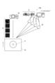
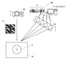
- FIG. 1 is a schematic diagram showing a schematic configuration of an image forming system according to a first embodiment
- FIG. 2 is a block diagram showing the functional configuration of the image forming system of the first embodiment
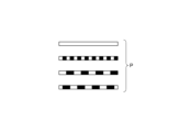
- FIG. It is an example of a one-dimensional structure illumination projection part. It is an example of a one-dimensional illumination pattern.
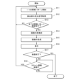
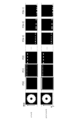
- 4 is a flowchart of image forming processing; It is a figure which shows the relationship between a scanning period and detection time.
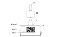
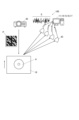
- FIG. 2 is a schematic diagram showing a schematic configuration of an image forming system according to a second embodiment
- FIG. It is an example of an illumination projection part of a two-dimensional structure. It is an example of a two-dimensional illumination pattern.
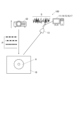
- FIG. 11 is a schematic diagram showing a schematic configuration of an image forming system according to a third embodiment
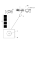
- FIG. 11 is a schematic diagram showing a schematic configuration of an image forming system according to a fourth embodiment
- FIG. 11 is a schematic diagram showing a schematic configuration of an image forming system according to another embodiment
- FIG. 11 is a schematic diagram showing a schematic configuration of an image forming system according to another embodiment
- FIG. 11 is a schematic diagram showing a schematic configuration of an image forming system according to another embodiment
- FIG. 11 is a schematic diagram showing a schematic configuration of an image forming system according to another embodiment
- FIG. 10 is a diagram showing the relationship between scan cycle and detection time in a conventional image forming system
- FIG. 10 is a diagram showing the relationship between scan cycle and detection time in a conventional image forming system
- FIG. 1 is a schematic diagram showing a schematic configuration of an image forming system 100 of the first embodiment. Then, the image forming system 100 is mainly used to output information about the appearance of the object, which is a non-luminous object.
- FIG. 1 is an example of observing a measuring object H having a glossy surface such as a metal electric saw blade.
- FIG. 2 is a block diagram showing the functional configuration of the image forming system 100 of this embodiment.
- the electric saw blade which is the object H to be measured, is placed on a pedestal portion 18 that moves at a substantially constant speed.
- the image forming system 100 includes a control section 11, an illumination projection section 12, a detection section 13, a storage section 14, a display section 15, an operation section 16, a communication section 17, and the like.
- the illumination projection unit 12 having a one-dimensional structure sequentially changes the one-dimensional illumination pattern P at regular intervals (scanning period s), and irradiates the measuring object H moving at a substantially constant speed. Then, the detector 13 detects reflected light from the object H to be measured, and sends a time-varying received light signal S to the controller 11 . Based on the sequentially changed one-dimensional illumination pattern P and the one-dimensional light reception signal S corresponding to each one-dimensional illumination pattern P, the control unit 11 uses the SPI technique to scan a constant period (scan period s), a one-dimensionally reconstructed reconstructed image (first image) is generated, and a two-dimensional second image is generated by arranging the first images.
- the control unit 11 includes a CPU (Central Processing Unit), a RAM (Random Access Memory), and the like.
- the control unit 11 is connected to each unit (the illumination projection unit 12, the detection unit 13, the storage unit 14, the display unit 15, the operation unit 16, and the communication unit 17) of the image forming system 100, and controls the operation of each unit.
- the control unit 11 cooperates with the programs stored in the storage unit 14 to execute various processes including image forming processing, which will be described later.
- the control unit 11 controls the illumination pattern P of the illumination projection unit 12 as an illumination control unit. Also, the control unit 11 controls the scan period s and the detection time t.
- the scan cycle s is the time for the image forming system 100 to one-dimensionally read (scan) the measurement object H for each fixed distance d (movement distance d) in which the measurement object H is moved. In other words, it is the time for the measuring object H to move by the constant distance d.
- each illumination pattern P irradiation area of the measurement object H may be read (scanned).
- the detection time t is the time during which all the illumination patterns P are sequentially irradiated and the detection unit 13 detects the reflected light. The relationship between the scan period s and the detection time t will be described later in detail.
- control unit 11 acquires the light intensity (light receiving signal S) corresponding to the illumination pattern P from the detecting unit 13, and from the illumination pattern P and the light intensity (light receiving signal S), every constant cycle (scan cycle s) , to generate a first image reconstructed in one dimension. Further, the control unit 11 generates a new second image based on a plurality of first images generated at regular intervals (scanning cycle s).
- the illumination projection unit 12 is, for example, a projection projector with a one-dimensional structure using a DMD (Digital Mirror Device). Note that the illumination projection unit 12 may be various projectors, and is not limited to a projection projector using a DMD. As shown in FIG. 3, the illumination projection unit 12 sequentially changes the one-dimensional illumination pattern P shown in FIG. The resolution of the one-dimensional illumination pattern P irradiated by the illumination projection unit 12 affects the resolution of the reconstructed image, and the number of irradiated one-dimensional illumination patterns P also affects the resolution of the reconstructed image. do. Although the DMD has a frame rate of 60 Hz or 120 Hz, the two-dimensional illumination pattern P per unit time can be increased by the following technique.
- the DMD is capable of projecting the bits of an image in sequence.
- one pixel of an image consists of 8 bits each of RGB, totaling 24 bits.
- an image in which one pixel is expressed by one bit cannot express gradation, and only a so-called black-and-white image can be projected.
- an image expressed as a so-called black-and-white image such as Hadamard illumination, as an illumination pattern, it is possible to project an image 24 times the frame rate in a unit time.
- the detection unit 13 measures the light intensity (light receiving signal S) of reflected light from the measuring object H with respect to the light of each illumination pattern P that is sequentially irradiated.
- the detection unit 13 includes, for example, a two-dimensional sensor such as a CCD (Charge-Coupled Device), a one-dimensional sensor such as a line CCD, an array of photodiodes (photodetectors), a single photodiode (photodetector), and the like. Available.
- the storage unit 14 is composed of a nonvolatile semiconductor memory, a hard disk, or the like, and includes a program executed by the control unit 11, data necessary for executing the program, an illumination pattern P, a light reception signal S of the detection unit 13, various generated Images, shooting history, etc. are stored. Note that the illumination pattern P is created by the control unit 11 . Moreover, the illumination pattern P may be stored in the storage unit 14 in advance.
- the display unit 15 displays the operation screen, the operation status of the image forming system 100, etc. on the display according to the display control of the control unit 11.
- FIG. 15 displays the operation screen, the operation status of the image forming system 100, etc. on the display according to the display control of the control unit 11.
- the operation unit 16 includes a group of keys used for input operations such as processing start and a touch panel integrated with the display of the display unit 15 , and generates operation signals according to these operations and outputs them to the control unit 11 . do.
- the communication unit 17 has a communication interface and communicates with external devices on the network.
- control unit 11 causes the illumination projection unit 12 to irradiate the measurement object H with one illumination pattern P in a certain scan cycle s (step S11).
- control unit 11 acquires the received light signal S, which is the received light from the measurement object H, from the detection unit 13 (step S12).
- control unit 11 determines whether all the illumination patterns P have been emitted by the illumination projection unit 12 (step S13). If all the illumination patterns P have been emitted by the illumination projection unit 12 (step S13; YES), proceed to step S14. , the control unit 11 causes the illumination projection unit 12 to irradiate the next illumination pattern P, in step S11.
- the control unit 11 reconstructs a one-dimensional image (first image) from the one-dimensional illumination pattern P and the received light signal S in a certain scan period s (step S14). Specifically, during the detection time t in a certain scan cycle s, the measurement object H is assumed to be substantially stationary, and the control unit 11 controls all the primary A one-dimensional image (first image) is reconstructed from the original illumination pattern P and the received light signal S corresponding to each illumination pattern P using SPI. That is, a one-dimensional image (first image) of the illumination pattern P irradiation area of the measurement object H is reconstructed.
- control unit 11 generates a two-dimensional second image using the first image in each scan period s (step S15). Specifically, the control unit 11 generates a two-dimensional second image by arranging the first images in each scan period s in order of the scan period s.
- control unit 11 displays the second image on the display unit 15 (step S16).
- control unit 11 determines whether the inspection is finished based on the instruction from the operation unit 16 (step S17). If the inspection is completed (step S17; YES), the image forming process is completed. If the inspection is not completed (step S17; NO), the process proceeds to step S18. Note that the control unit 11 may automatically determine the end of the inspection. For example, if there is an abnormality in the measurement object H on the second image, the control unit 11 automatically determines and ends the inspection.
- step S18 determines whether or not the scanning cycle s has passed since the timing when the illumination projection unit 12 was caused to irradiate the measurement object H with the first illumination pattern P in step S11 (step S18). If the scan period s has elapsed (step S18; YES), the process proceeds to step S11 to sequentially irradiate all the illumination patterns P again. If the scan period s has not elapsed (step S18; NO), the process proceeds to step S18. That is, step S18 is repeated until the scan cycle s elapses.
- FIG. The detection time t is the time during which all the illumination patterns P are sequentially irradiated and the detection unit 13 detects the reflected light.
- Step S13; YES indicates the time.
- the scan period s is the time for the image forming system 100 to one-dimensionally read the measurement object H for each illumination pattern P irradiation area of the measurement object H. It indicates the time from the start of the loop (step S11) to the end (step S18; YES).
- FIG. 18 is a diagram showing the relationship between the scan period s and the detection time t in the case where a conventional line sensor camera or standard SPI is applied one-dimensionally.
- the illumination pattern is repeated in order as 1, 2, 3 . . . N, 1, 2, 3 . In order to keep switching, the scan period and the detection time t had to be substantially matched.
- step S14 to step S17 is performed in parallel with steps S11 to S13 and step S18. In other words, even if the processes of reconstruction of the first image in step S14, generation of the second image in step S15, display of the second image in step S16, and determination of inspection end in step S17 have not been completed for a long time. If, in step S11, the scan cycle s has elapsed since the timing at which the first illumination pattern P was irradiated, it is determined in step S18 that the scan cycle s has elapsed (step S18; YES), and the process proceeds to step S11.
- FIG. 7 is a schematic diagram showing a schematic configuration of the image forming system 100 of the second embodiment.
- FIG. 7 is a schematic diagram showing a schematic configuration of the image forming system 100 of the second embodiment.
- the illumination projection unit 22 having a two-dimensional structure sequentially changes the one-dimensional illumination pattern P at regular intervals (scanning period s), and irradiates the measuring object H moving at a substantially constant speed. Then, the detector 13 detects reflected light from the object H to be measured, and sends a time-varying received light signal S to the controller 11 . Then, based on the sequentially changed one-dimensional illumination pattern P and the one-dimensional light receiving signal S corresponding to each illumination pattern P, the control unit 11 uses SPI technology to perform scanning at regular intervals (scan intervals s). First, a one-dimensional reconstructed image (first image) is generated, and a two-dimensional second image is generated by arranging the first images.
- first image a one-dimensional reconstructed image
- second image is generated by arranging the first images.
- the illumination projection unit 22 is, for example, a two-dimensional structure projection projector using a DMD (Digital Mirror Device). As shown in FIG. 8, the illumination projection unit 22, for example, projects the two-dimensional illumination pattern P shown in FIG. -1]; the one-dimensional illumination pattern P) is sequentially changed, and the object H to be measured is illuminated.
- DMD Digital Mirror Device
- All illumination patterns P are assumed to be stored in the storage unit 14 . Further, in FIG. 10, all illumination patterns P refer to the one-dimensional illumination pattern P for all rows of the two-dimensional illumination pattern P, and one illumination pattern P refers to the one-dimensional illumination pattern P for each row. .
- steps S21 to S23 are the same as steps S11 to S13 in FIG.
- the control unit 11 determines whether or not the illumination projection unit 22 has caused the illumination projection unit 22 to irradiate all the illumination patterns P onto the same portion of the measurement object H (step S24). Specifically, for example, when all the illumination patterns P are successively illuminated several times in the two-dimensional illumination pattern P, the part at the distance d from the front end in the moving direction of the measurement object H is not illuminated by all illumination. Since the pattern P is irradiated, the one-dimensional image (first image) can be reconstructed in step S25.
- step S24 When the control unit 11 determines that the illumination projection unit 22 has caused the illumination projection unit 22 to irradiate all the illumination patterns P onto the same location of the measurement object H (step S24; YES), the process proceeds to step S25, and a one-dimensional image (first image ) is reconstructed. On the other hand, if the control unit 11 does not determine that irradiation has been performed (step S24; NO), the process proceeds to step S28.
- FIG. 11 shows a one-dimensional illumination pattern P sequentially irradiated onto the measurement object H in each scan period s by the illumination projection unit 22 .
- the arrow shown on the left side of the measurement target H indicates the direction in which the measurement target H moves.
- the moving direction of the measuring object H coincides with the moving direction of the row of the one-dimensional illumination pattern P in the two-dimensional illumination pattern P.
- FIG. the movement direction of the columns of the one-dimensional illumination pattern P in the two-dimensional illumination pattern P is opposite.
- all the illumination patterns P are sequentially irradiated (the number of columns ⁇ 1) times of the two-dimensional illumination pattern P, and the last primary of the illumination pattern P in the immediately following scan period s
- all the illumination pattern P is illuminated for the portion of the distance d from the front end in the moving direction of the measurement object H, and in the case of FIG. (the number of rows ⁇ 1) times of the pattern P, all the illumination patterns P are successively illuminated, and immediately after that the one-dimensional illumination pattern P is illuminated, the distance d from the front end of the measurement object H in the moving direction. All the illumination patterns P are applied to the part, and the reconstruction of the first image can be started in step S25.
- the reconstruction of the image in step S25 is performed using the following equation (1).
- the two-dimensional illumination pattern P has M rows and N columns
- the two-dimensional second image (measurement object H) is an image represented by M rows and q columns.
- the first image for each row of the two-dimensional second image (object H to be measured) is represented by T[n], T[n+1], T[n+2] . . . T[n+q ⁇ 1].
- T[j] in the scan period s(i, 1 to N) is illuminated with P[i ⁇ 1] and the light amount of I_i_j is detected by the detection unit 13 .
- the area of T[j] is illuminated with P[i ⁇ 1] at the scan period s(i)
- the amount of light of I_i_j is measured
- the amount of light of P[i ⁇ 1 ] is illuminated
- the amount of light I'_i_j is measured
- the reconstruction of the image in step S25 is performed using equation (2) below.
- E_i(I_i_j) is the average value of I_i_j for i.
- E_i(P[i-1]) is an M-row ⁇ 1-column matrix obtained by averaging P[i-1] for i.
- steps S26 to S29 are the same as steps S15 to S18 in FIG.
- FIG. 12 is a schematic diagram showing the schematic configuration of the image forming system 100 of the third embodiment.
- FIG. 12 shows the schematic configuration of the image forming system 100 of the third embodiment.
- the illumination projection unit 32 having a two-dimensional structure sequentially changes the two-dimensional illumination pattern P at each constant cycle (scan cycle s), and irradiates the measurement object H moving at a substantially constant speed.
- a plurality of detectors 33 detect reflected light from the object H to be measured, and send a time-varying received light signal S to the controller 11 .
- the control unit 11 based on the sequentially changed two-dimensional illumination pattern P and the one-dimensional light reception signal S corresponding to each column (four columns in the third embodiment) of the two-dimensional illumination pattern P, the control unit 11 Using the SPI technique, a reconstructed image (first image) that is one-dimensionally reconstructed for each row of the two-dimensional illumination pattern P is generated for each constant cycle (scan cycle s), and the first image is A two-dimensional second image is generated by arranging them.
- the illumination projection unit 32 is, for example, a two-dimensional structure projection projector using a DMD (Digital Mirror Device). As shown in FIG. 12, the illumination projection unit 32, for example, in the two-dimensional illumination pattern P shown in FIG. [12] ⁇ , ⁇ P[1], P[5], P[9], P[13] ⁇ ... ⁇ P[N-13], P[N-9], P[N-5] , P[N ⁇ 1] ⁇ ; two-dimensional illumination pattern P), and illuminates the object H to be measured.
- DMD Digital Mirror Device
- a plurality of detectors 33 are required (at least four detectors in the third embodiment) to detect time-varying one-dimensional light reception signals S corresponding to each row (four rows in the third embodiment) of the two-dimensional illumination pattern P. required).
- the rows of the two-dimensional illumination pattern P to be irradiated are spaced apart, or It is good to provide partitions.
- the illumination projection unit 22 sequentially irradiates each row of the two-dimensional illumination pattern P in the second embodiment. In the form, irradiation is sequentially performed every four rows).
- FIG. 13 is a schematic diagram showing a schematic configuration of the image forming system 100 of the fourth embodiment.
- modes different from the first to third embodiments will be described.
- the illumination projection unit 42 having a two-dimensional structure irradiates a two-dimensional illumination pattern P onto the measuring object H moving at a substantially constant speed at each constant cycle (scan cycle s).
- a plurality of detectors 43 detect reflected light from the object H to be measured, and send light reception signals S to the controller 11 .
- the control unit 11 Based on the two-dimensional illumination pattern P and the one-dimensional light receiving signal S corresponding to each row (all rows in the fourth embodiment) of the two-dimensional illumination pattern P, the control unit 11 uses the SPI technology to Then, a reconstructed image (first image) that is one-dimensionally reconstructed for each row of the two-dimensional illumination pattern P is generated for each fixed period (scan period s), and the first images are arranged. Generate a second image of the dimension.
- the illumination projection unit 42 is, for example, a two-dimensional structure projection projector using a DMD (Digital Mirror Device). As shown in FIG. 13, the illumination projection unit 42, for example, projects the two-dimensional illumination pattern P shown in FIG. -1]; a two-dimensional illumination pattern P) is applied to the object H to be measured.
- DMD Digital Mirror Device
- the detector 43 detects the one-dimensional light reception signal S corresponding to each row (all rows in the fourth embodiment) of the two-dimensional illumination pattern P, so there are as many as the number of rows of the two-dimensional illumination pattern P.
- the illumination projection unit 42 instead of the illumination projection unit 22 sequentially irradiating each row of the two-dimensional illumination pattern P in the second embodiment, the illumination projection unit 42 That is, the two-dimensional illumination pattern P is all arranged to be illuminated at once.
- the image forming system 100 does not move with respect to the measurement object H moving at a substantially constant speed.
- a configuration in which the measuring object H does not move with respect to the projection unit) may also be used.
- the one-dimensional illumination pattern P is sequentially changed at each constant cycle (scan cycle s) by the one-dimensional illumination projection unit 52 that moves at a substantially constant speed. and irradiates the object H to be measured. Note that the flow of image forming processing is the same as in FIG. In the image forming system 100 shown in FIG.
- an illumination projection unit 62 having a two-dimensional structure that moves at a substantially constant speed sequentially changes a one-dimensional illumination pattern P at each constant cycle (scan cycle s) to Irradiate H.
- the flow of image forming processing is the same as in FIG.
- the two-dimensional illumination pattern P (a plurality of rows; for example, four rows) is generated by the illumination projection unit 72 having a two-dimensional structure that moves at a substantially constant speed at each constant cycle (scanning cycle s). are sequentially changed, and the object H to be measured is irradiated.
- the flow of the image forming process is the same as in FIG. In the image forming system 100 shown in FIG.
- an illumination projection unit 82 having a two-dimensional structure that moves at a substantially constant speed projects a two-dimensional illumination pattern P (all columns) to the measurement object at regular intervals (scan intervals s). Irradiate object H.
- the detection unit 73 and the detection unit 83 detect the one-dimensional light receiving signal S corresponding to each row of the two-dimensional illumination pattern P. Similar to the form, a plurality of them are necessary, and they need to move in the same direction and at the same speed as the illumination projection unit 72 and the illumination projection unit 82 that move at substantially the same speed. Also in the case of FIGS. 14 and 15, the detection unit 13 may be moved.
- the image forming system 100 includes the illumination projection unit 12 that irradiates the measurement object moving at a substantially constant speed with light of a plurality of illumination patterns, and the light reflected from the measurement object by the light of the illumination pattern.
- a detection unit 13 that detects light intensity
- an illumination control unit control unit 11
- a generation unit control unit 11
- a generation unit control unit 11 that generates a two-dimensionally reconstructed image from the light intensity of the reflected light, so that a single-element detector can detect a moving object in one dimension or Acquiring a two-dimensional image can be realized.
- the direction of movement of the object to be measured is defined as rows, and the direction orthogonal to the direction of movement is defined as columns.
- the unit (control unit 11) causes the illumination projection unit 12 to sequentially irradiate light of a plurality of one-dimensional illumination patterns, and the generation unit (control unit 11) generates a first image, which is a one-dimensional reconstructed image in the column direction. Since one image is generated and the second image, which is a two-dimensional reconstructed image, is generated based on the first image, the number of illumination patterns P in each scan period s can be reduced.
- the illumination pattern consists of N ⁇ N pixels
- a squared pattern of N or a squared pattern of 2 ⁇ N is required.
- an N pattern or a 2N pattern is sufficient when irradiating a one-dimensional illumination pattern.
- the moving direction of the object to be measured is defined as rows, and the direction orthogonal to the moving direction is defined as columns.
- the unit 11) causes the illumination projection unit 22 to sequentially irradiate light of a two-dimensional illumination pattern for each column, and the generation unit (control unit 11) generates a first image that is a one-dimensional reconstructed image in the column direction. is generated, and the second image, which is a two-dimensional reconstructed image, is generated based on the first image, so the number of illumination patterns P in each scan cycle s can be reduced.
- the moving direction of the object to be measured is the row
- the direction orthogonal to the moving direction is the column
- the illumination projection unit (illumination projection unit 32 or illumination projection unit 42) has a two-dimensional structure
- the illumination control unit causes the illumination projection unit (illumination projection unit 32 or illumination projection unit 42) to sequentially irradiate light of a two-dimensional illumination pattern for each of a plurality of columns
- the detection unit (detection unit 33 or The detection unit 43) has a number equal to or greater than the number of the irradiated plural rows, and detects the light intensity of the reflected light corresponding to each light of the rows of the illumination pattern.
- the signals are acquired at once, further reducing the number of illumination patterns P in each scan period s. Specifically, when the number of rows of two-dimensional illumination patterns to be sequentially irradiated is k rows, the number of illumination patterns P in each scan cycle s is 1/k times the number of illumination patterns P compared to the case of irradiating a one-dimensional illumination pattern. can be reduced to
- the image forming system 100 includes an illumination projection unit 52 that irradiates the object to be measured with light of a plurality of illumination patterns and that moves at a substantially constant speed, and the light intensity of the light reflected from the object to be measured by the light of the illumination pattern.
- a detection unit 13 for detection an illumination control unit (control unit 11) that sequentially switches an illumination pattern from among a plurality of illumination patterns and irradiates light from an illumination projection unit 12, an illumination pattern and reflected light corresponding to the illumination pattern and a generation unit (control unit 11) that generates a reconstructed image that is two-dimensionally reconstructed from the light intensity of the single-element detector. It is possible to achieve the acquisition of
- the direction of movement of the illumination projection unit 52 is defined as rows, and the direction perpendicular to the direction of movement is defined as columns.
- the control unit causes the illumination projection unit 52 to sequentially irradiate light of a plurality of one-dimensional illumination patterns, and the generation unit (control unit 11) generates a one-dimensional reconstructed image in the column direction. Since the first image is generated and the second image, which is a two-dimensional reconstructed image, is generated based on the first image, the number of illumination patterns P in each scan cycle s can be reduced.
- the direction of movement of the illumination projection unit 62 is defined as rows, and the direction perpendicular to the direction of movement is defined as columns.
- the control unit 11) causes the illumination projection unit 62 to sequentially irradiate light of a two-dimensional illumination pattern for each row, and the generation unit (control unit 11) directs the first image, which is a one-dimensional reconstructed image in the column direction.
- the number of illumination patterns P in each scan period s can be reduced because the images are generated and based on the first images, the second images, which are two-dimensional reconstructed images, are generated.
- the moving direction of the illumination projection unit is defined as a row
- the direction orthogonal to the movement direction is defined as a column
- the illumination projection unit (illumination projection unit 72 or illumination projection unit 72) is defined as a column.
- unit 82) irradiates light of a two-dimensional illumination pattern
- the illumination control unit causes the illumination projection unit (illumination projection unit 72 or illumination projection unit 82) to emit light of the two-dimensional illumination pattern.
- the detector detector 73 or detector 83
- the generation unit (control unit 11) generates a first image that is a one-dimensional reconstructed image in the column direction for each column, and generates a second image that is a two-dimensional reconstructed image based on the first image. Therefore, in one irradiation, the received light signals for each of the plurality of columns are acquired at once, and the number of illumination patterns P in each scan cycle s can be further reduced.
- the illumination control unit (control unit 11) separately controls the detection time in the detection unit 13 and the period at which the image forming system 100 reads the measurement object
- the moving speed of the measurement object H is adjusted to can be arbitrarily slow. That is, by arbitrarily slowing down the moving speed of the measuring object H, it is possible to further reduce the number of illumination patterns P irradiated per unit time.
- the detection unit 13 is a photodiode, it is inexpensive.
- the illumination projection unit 12 includes a DMD, and the illumination control unit (control unit 11) associates the bit-by-bit RGB image with the clock frequency of the DMD, and converts the bit-by-bit RGB image to Since it is projected by the illumination projection unit 12 as an independent pattern, it is possible to increase the number of two-dimensional illumination patterns per unit time.
- the image forming method includes sequentially switching light of a plurality of illumination patterns to irradiate an object to be measured which moves at a substantially constant speed, and detecting the light intensity of light reflected from the object to be measured by the light of the illumination pattern. , a two-dimensionally reconstructed image is generated from the illumination pattern and the light intensity of the reflected light corresponding to the illumination pattern. It becomes possible to realize to acquire a dimensional or two dimensional image.
- the image forming method moves at a substantially constant speed, sequentially switches the light of a plurality of illumination patterns, irradiates the measurement object, and detects the light intensity of the light reflected from the measurement object by the light of the illumination pattern. Then, a reconstructed image that is two-dimensionally reconstructed from the illumination pattern and the light intensity of the reflected light corresponding to the illumination pattern is generated. It becomes possible to realize to acquire a dimensional or two dimensional image.
- the program includes an illumination projection unit 12 that irradiates light of a plurality of illumination patterns onto an object to be measured that moves at a substantially constant speed, and a detection that detects the light intensity of light reflected from the object to be measured by the light of the illumination pattern.
- an illumination control unit (control unit 11) that causes the computer of the image forming system 100 to sequentially switch illumination patterns from among a plurality of illumination patterns and irradiate light from the illumination projection unit 12;
- a single-element detector detects a moving object. It is possible to obtain a one-dimensional or two-dimensional image of the .
- the program also includes an illumination projection unit 12 that irradiates a measurement object with light of a plurality of illumination patterns and that moves at a substantially constant speed, and a detection that detects the light intensity of light reflected from the measurement object by the light of the illumination pattern.
- an illumination control unit (control unit 11) that causes the computer of the image forming system 100 to sequentially switch illumination patterns from among a plurality of illumination patterns and irradiate light from the illumination projection unit 12;
- a single-element detector detects the object while moving. Acquiring one-dimensional or two-dimensional images can be realized.
- the pedestal portion 18 of the object be made of a member that does not easily reflect the light of the projection projector.
- light other than the illumination projection unit 12, for example, from indoor lighting is also reflected by the object and becomes a factor that lowers the S/N ratio of the analysis device. can be created.
- each detection unit 13 emits a one-dimensional illumination pattern that constitutes a different two-dimensional illumination pattern P, and detects reflected light.
- the number of illumination is several times that of the second embodiment (“the number of different two-dimensional illumination patterns P”), so that the quality of the first image can be improved.
- the N detectors may be N single detectors such as photodiodes, and a combination of a line sensor and a cylindrical lens may be used. Multiple DMD projector and single detector combinations may be provided.
- an example using a hard disk, a semiconductor non-volatile memory, or the like is disclosed as a computer-readable medium for the program according to the present invention, but the present invention is not limited to this example.
- portable recording media such as CD-ROMs can be applied.
- a carrier wave is also applied as a medium for providing program data according to the present invention via a communication line.
- the present disclosure can be used for image forming systems, image forming methods, and programs.
- control unit 12 illumination projection unit 13 detection unit 14 storage unit 15 display unit 16 operation unit 17 communication unit 22 illumination projection unit 32 illumination projection unit 33 detection unit 42 illumination projection unit 43 detection unit 52 illumination projection unit 62 illumination Projector 72 Illumination Projector 73 Detector 82 Illuminator Projector 83 Detector
Landscapes
- Physics & Mathematics (AREA)
- General Physics & Mathematics (AREA)
- Engineering & Computer Science (AREA)
- Theoretical Computer Science (AREA)
- Health & Medical Sciences (AREA)
- Life Sciences & Earth Sciences (AREA)
- Chemical & Material Sciences (AREA)
- Analytical Chemistry (AREA)
- Biochemistry (AREA)
- General Health & Medical Sciences (AREA)
- Immunology (AREA)
- Pathology (AREA)
- Multimedia (AREA)
- Signal Processing (AREA)
- Investigating Materials By The Use Of Optical Means Adapted For Particular Applications (AREA)
- Image Input (AREA)
- Image Processing (AREA)
- Length Measuring Devices By Optical Means (AREA)
Abstract
単一素子の検出器で、動いている対象物の一次元また二次元の画像を取得する又は動きながら対象物の一次元また二次元の画像を取得することを実現することができる画像形成システム、画像形成方法、及びプログラムを提供する。画像形成システム100は、複数の照明パターンの光を、略等速度で移動する測定対象物に照射する照明投影部12と、照明パターンの光による測定対象物からの反射光の光強度を検出する検出部13と、複数の照明パターンの中から順次照明パターンを切り替えて照明投影部12から光を照射させる照明制御部(制御部11)と、照明パターンと当該照明パターンに対応した反射光の光強度から二次元に再構成された再構成画像を生成する生成部(制御部11)と、を備える。
Description
本発明は、画像形成システム、画像形成方法、及びプログラムに関する。
従来、対象物の外観検査において、フォトダイオードやPMT(photomultiplier tube)などの単一素子の検出器を用いる場合がある。
そして、単一素子の検出器で一次元また二次元の画像を取得する方法として、特許文献1や特許文献2に示されているように、SPI(single pixel imaging)と呼ばれる手法が知られている。
そして、単一素子の検出器で一次元また二次元の画像を取得する方法として、特許文献1や特許文献2に示されているように、SPI(single pixel imaging)と呼ばれる手法が知られている。
SPIとは、対象物に対して、複数回の異なる照明パターンを照射して、その際の散乱光強度を単一素子の検出器で取得し、照明パターンに対する検出器の信号強度を基に一次元または二次元の画像を再構成するという手法である。
SPIでは、その手法の特性上、複数回の異なる照明パターンは同一箇所に照射される必要があるため、対象物や照明パターンの投影装置は共に静止していることが前提となっている。
したがって、工場における製造工程での対象物の外観検査を想定すると、ベルトコンベア上に乗せられた製品/部品や、ロールツーロールで生産されている製品などでは、静止することが困難であった。また、これらの製品は、連続的に生産されていて、1個1個の区切りがなかったりする。このため、移動する対象物の外観検査にSPIを適用されていなかった。また、動きながら対象物の外観検査を行う場合にも、SPIを適用されていなかった。
本発明の課題は、単一素子の検出器で、動いている対象物の一次元また二次元の画像を取得する又は動きながら対象物の一次元また二次元の画像を取得することを実現することである。
上記課題を解決するため、本発明の画像形成システムは、
複数の照明パターンの光を、略等速度で移動する測定対象物に照射する照明投影部と、
前記照明パターンの光による前記測定対象物からの反射光の光強度を検出する検出部と、
複数の前記照明パターンの中から順次前記照明パターンを切り替えて前記照明投影部から光を照射させる照明制御部と、
前記照明パターンと当該照明パターンに対応した反射光の前記光強度から二次元に再構成された再構成画像を生成する生成部と、
を備える。
複数の照明パターンの光を、略等速度で移動する測定対象物に照射する照明投影部と、
前記照明パターンの光による前記測定対象物からの反射光の光強度を検出する検出部と、
複数の前記照明パターンの中から順次前記照明パターンを切り替えて前記照明投影部から光を照射させる照明制御部と、
前記照明パターンと当該照明パターンに対応した反射光の前記光強度から二次元に再構成された再構成画像を生成する生成部と、
を備える。
上記課題を解決するため、本発明の画像形成システムは、
複数の照明パターンの光を測定対象物に照射する、略等速度で移動する照明投影部と、
前記照明パターンの光による前記測定対象物からの反射光の光強度を検出する検出部と、
複数の前記照明パターンの中から順次前記照明パターンを切り替えて前記照明投影部から光を照射させる照明制御部と、
前記照明パターンと当該照明パターンに対応した反射光の前記光強度から二次元に再構成された再構成画像を生成する生成部と、
を備える。
複数の照明パターンの光を測定対象物に照射する、略等速度で移動する照明投影部と、
前記照明パターンの光による前記測定対象物からの反射光の光強度を検出する検出部と、
複数の前記照明パターンの中から順次前記照明パターンを切り替えて前記照明投影部から光を照射させる照明制御部と、
前記照明パターンと当該照明パターンに対応した反射光の前記光強度から二次元に再構成された再構成画像を生成する生成部と、
を備える。
また、本発明の画像形成方法は、
複数の照明パターンの光を、順次切り替えて、略等速度で移動する測定対象物に照射し、
前記照明パターンの光による前記測定対象物からの反射光の光強度を検出し、
前記照明パターンと当該照明パターンに対応した反射光の前記光強度から二次元に再構成された再構成画像を生成する。
複数の照明パターンの光を、順次切り替えて、略等速度で移動する測定対象物に照射し、
前記照明パターンの光による前記測定対象物からの反射光の光強度を検出し、
前記照明パターンと当該照明パターンに対応した反射光の前記光強度から二次元に再構成された再構成画像を生成する。
また、本発明の画像形成方法は、
略等速度で移動し、複数の照明パターンの光を、順次切り替えて、測定対象物に照射し、
前記照明パターンの光による前記測定対象物からの反射光の光強度を検出し、
前記照明パターンと当該照明パターンに対応した反射光の前記光強度から二次元に再構成された再構成画像を生成する。
略等速度で移動し、複数の照明パターンの光を、順次切り替えて、測定対象物に照射し、
前記照明パターンの光による前記測定対象物からの反射光の光強度を検出し、
前記照明パターンと当該照明パターンに対応した反射光の前記光強度から二次元に再構成された再構成画像を生成する。
また、本発明のプログラムは、
複数の照明パターンの光を、略等速度で移動する測定対象物に照射する照明投影部と、前記照明パターンの光による前記測定対象物からの反射光の光強度を検出する検出部と、とを備える画像形成システムのコンピューターを、
複数の前記照明パターンの中から順次前記照明パターンを切り替えて前記照明投影部から光を照射させる照明制御部、
前記照明パターンと当該照明パターンに対応した反射光の前記光強度から二次元に再構成された再構成画像を生成する生成部、
として機能させる。
複数の照明パターンの光を、略等速度で移動する測定対象物に照射する照明投影部と、前記照明パターンの光による前記測定対象物からの反射光の光強度を検出する検出部と、とを備える画像形成システムのコンピューターを、
複数の前記照明パターンの中から順次前記照明パターンを切り替えて前記照明投影部から光を照射させる照明制御部、
前記照明パターンと当該照明パターンに対応した反射光の前記光強度から二次元に再構成された再構成画像を生成する生成部、
として機能させる。
また、本発明のプログラムは、
複数の照明パターンの光を測定対象物に照射する、略等速度で移動する照明投影部と、前記照明パターンの光による前記測定対象物からの反射光の光強度を検出する検出部と、とを備える画像形成システムのコンピューターを、
複数の前記照明パターンの中から順次前記照明パターンを切り替えて前記照明投影部から光を照射させる照明制御部、
前記照明パターンと当該照明パターンに対応した反射光の前記光強度から二次元に再構成された再構成画像を生成する生成部、
として機能させる。
複数の照明パターンの光を測定対象物に照射する、略等速度で移動する照明投影部と、前記照明パターンの光による前記測定対象物からの反射光の光強度を検出する検出部と、とを備える画像形成システムのコンピューターを、
複数の前記照明パターンの中から順次前記照明パターンを切り替えて前記照明投影部から光を照射させる照明制御部、
前記照明パターンと当該照明パターンに対応した反射光の前記光強度から二次元に再構成された再構成画像を生成する生成部、
として機能させる。
本発明によれば、単一素子の検出器で、動いている対象物の一次元また二次元の画像を取得する又は動きながら対象物の一次元また二次元の画像を取得できる。
以下、図面を参照して本発明の実施形態について説明する。ただし、以下に述べる実施形態には、本発明を実施するために技術的に好ましい種々の限定が付されているが、本発明の技術的範囲を以下の実施形態および図示例に限定するものではない。特に、図面は、説明の都合上簡略されており、照明パターンと対象物との比率とは異なる場合がある。
<第1実施形態>
(画像形成システムの構成)
図1は、第1実施形態の画像形成システム100の概略構成を示す概略図である。そして、画像形成システム100は、主に非発光物体である対象物の外観に関する情報を出力するために用いられる。
(画像形成システムの構成)
図1は、第1実施形態の画像形成システム100の概略構成を示す概略図である。そして、画像形成システム100は、主に非発光物体である対象物の外観に関する情報を出力するために用いられる。
図1は、金属製の電動のこぎり刃のような光沢面を有する測定対象物Hを観察する場合の例である。図2は、本実施形態の画像形成システム100の機能構成を示すブロック図である。ここで、測定対象物Hである電動のこぎり刃は、略等速度で移動する台座部18に配置されている。
図1、図2に示すように、画像形成システム100は、制御部11、照明投影部12、検出部13、記憶部14、表示部15、操作部16、通信部17などを備える。
画像形成システム100では、一定周期(スキャン周期s)毎に、一次元構造の照明投影部12により一次元の照明パターンPを順次変更し、略等速度で移動する測定対象物Hに照射する。そして、測定対象物Hからの反射光を検出部13が検出し、時間変動する受光信号Sを制御部11に送る。そして、制御部11は、順次変更された一次元の照明パターンPと、各一次元の照明パターンPに対応する一次元の受光信号Sを基に、SPI技術を用いて、一定周期(スキャン周期s)毎に、一次元に再構成された再構成画像(第1画像)を生成し、その第1画像を並べることで二次元の第2画像を生成する。
制御部11は、CPU(Central Processing Unit)やRAM(Random Access Memory)等から構成されている。制御部11は、画像形成システム100の各部(照明投影部12、検出部13、記憶部14、表示部15、操作部16、通信部17)に接続されており、各部の動作を制御する。また、制御部11は、記憶部14に記憶されているプログラムとの協働により、後述する画像形成処理を始めとする各種処理を実行する。
制御部11は、照明制御部として照明投影部12の照明パターンPを制御する。
また、制御部11は、スキャン周期sと検出時間tを制御する。ここで、スキャン周期sとは、測定対象物Hの移動した一定距離d(移動距離d)ずつ、画像形成システム100が、一次元的に測定対象物Hを読み取る(スキャン)時間である。つまり、測定対象物Hが一定距離dだけ移動する時間である。なお、測定対象物Hの照明パターンP照射領域ずつ読み取ってもよい(スキャン)。また、検出時間tは、全ての照明パターンPを順次照射し、検出部13が反射光を検出する時間である。スキャン周期sと検出時間tの関係については、詳しくは後述する。
また、制御部11は、照明パターンPに対応した光強度(受光信号S)を検出部13から取得し、照明パターンPと光強度(受光信号S)から、一定周期(スキャン周期s)毎に、一次元に再構成された第1画像を生成する。
また、制御部11は、一定周期(スキャン周期s)毎に生成された複数の第1画像に基づいて、新たな第2画像を生成する。
制御部11は、照明制御部として照明投影部12の照明パターンPを制御する。
また、制御部11は、スキャン周期sと検出時間tを制御する。ここで、スキャン周期sとは、測定対象物Hの移動した一定距離d(移動距離d)ずつ、画像形成システム100が、一次元的に測定対象物Hを読み取る(スキャン)時間である。つまり、測定対象物Hが一定距離dだけ移動する時間である。なお、測定対象物Hの照明パターンP照射領域ずつ読み取ってもよい(スキャン)。また、検出時間tは、全ての照明パターンPを順次照射し、検出部13が反射光を検出する時間である。スキャン周期sと検出時間tの関係については、詳しくは後述する。
また、制御部11は、照明パターンPに対応した光強度(受光信号S)を検出部13から取得し、照明パターンPと光強度(受光信号S)から、一定周期(スキャン周期s)毎に、一次元に再構成された第1画像を生成する。
また、制御部11は、一定周期(スキャン周期s)毎に生成された複数の第1画像に基づいて、新たな第2画像を生成する。
照明投影部12は、例えば、DMD(Digital Mirror Device)を用いた一次元構造の投影プロジェクタである。なお、照明投影部12は、各種プロジェクタでもよく、DMDを用いた投影プロジェクタに限定されない。
照明投影部12は、図3に示すように、例えば、図4に示す一次元の照明パターンPを、順次変更し、測定対象物Hに対して照射する。
なお、照明投影部12により照射される一次元の照明パターンPの解像度は、再構成画像の解像度に影響すると共に、照射する一次元の照明パターンPの照射枚数も再構成画像の解像度にも影響する。
また、DMDのフレームレートは60Hzとか120Hzではあるが次の手法により、単位時間当たりの二次元の照明パターンPを増加させる事が出来る。
DMDはその原理的な特徴から、画像のビットを順々に投影することが可能である。また、一般に画像の1画素はRGB各8ビットの計24ビットで構成されており、各ビットを1枚の画像としてDMDのクロック周波数に対して対応させ、順々に投影する。ただし、1画素が1ビットで表現される画像は諧調の表現は不可能であり、いわゆる白黒画像のみが投影可能である。例えばアダマール照明のように、いわゆる白黒画像として表現される画像を照明パターンとして用いることで、フレームレートの24倍の画像を単位時間で投影可能となる。
照明投影部12は、図3に示すように、例えば、図4に示す一次元の照明パターンPを、順次変更し、測定対象物Hに対して照射する。
なお、照明投影部12により照射される一次元の照明パターンPの解像度は、再構成画像の解像度に影響すると共に、照射する一次元の照明パターンPの照射枚数も再構成画像の解像度にも影響する。
また、DMDのフレームレートは60Hzとか120Hzではあるが次の手法により、単位時間当たりの二次元の照明パターンPを増加させる事が出来る。
DMDはその原理的な特徴から、画像のビットを順々に投影することが可能である。また、一般に画像の1画素はRGB各8ビットの計24ビットで構成されており、各ビットを1枚の画像としてDMDのクロック周波数に対して対応させ、順々に投影する。ただし、1画素が1ビットで表現される画像は諧調の表現は不可能であり、いわゆる白黒画像のみが投影可能である。例えばアダマール照明のように、いわゆる白黒画像として表現される画像を照明パターンとして用いることで、フレームレートの24倍の画像を単位時間で投影可能となる。
検出部13は、順次照射される各照明パターンPの光に対する測定対象物Hからの反射光の光強度(受光信号S)を測定する。
検出部13は、例えば、CCD(Charge-Coupled Device)のような二次元センサー、ラインCCDのような一次元センサー、フォトダイオード(フォトディテクター)のアレイ、単一のフォトダイオード(フォトディテクター)等が使用可能である。
検出部13は、例えば、CCD(Charge-Coupled Device)のような二次元センサー、ラインCCDのような一次元センサー、フォトダイオード(フォトディテクター)のアレイ、単一のフォトダイオード(フォトディテクター)等が使用可能である。
記憶部14は、不揮発性の半導体メモリーやハードディスク等により構成され、制御部11により実行されるプログラムやプログラムの実行に必要なデータ、照明パターンP、検出部13の受光信号S、各種生成された画像、撮影履歴等を記憶している。なお、照明パターンPは、制御部11にて作成される。また、照明パターンPは、あらかじめ記憶部14に記憶されていてもよい。
表示部15は、制御部11の表示制御に従って、ディスプレイに操作画面、画像形成システム100の動作状況等を表示する。
操作部16は、処理開始等の入力操作に用いるキー群の他、表示部15のディスプレイと一体に構成されたタッチパネルを備え、これらの操作に応じた操作信号を生成して制御部11に出力する。
通信部17は、通信インターフェイスを備え、ネットワーク上の外部機器と通信を行う。
(画像形成処理)
画像形成処理のフローを、図5を用いて説明する。なお、全ての照明パターンPは、記憶部14に記憶されているものとする。
画像形成処理のフローを、図5を用いて説明する。なお、全ての照明パターンPは、記憶部14に記憶されているものとする。
まず、制御部11は、あるスキャン周期sにおいて、照明投影部12に、1つの照明パターンPを測定対象物Hに照射させる(ステップS11)。
次に、制御部11は、検出部13から、測定対象物Hからの光を受信した受光信号Sを取得する(ステップS12)。
次に、制御部11は、全ての照明パターンPを照明投影部12に照射させたか判断する(ステップS13)。全ての照明パターンPを照明投影部12に照射させた場合(ステップS13;YES)、ステップS14に進み、全ての照明パターンPを照明投影部12に照射させ終わっていない場合(ステップS13;NO)、ステップS11に進み、制御部11は、照明投影部12に次の照明パターンPを照射させる。
次に、制御部11は、あるスキャン周期sにおける一次元の照明パターンPと受光信号Sから一次元の画像(第1画像)を再構成する(ステップS14)。具体的には、あるスキャン周期sにおける検出時間tの間に、測定対象物Hは略停止しているとみなし、制御部11は、測定対象物Hの同一箇所に順次照射された全ての一次元の照明パターンPと各照明パターンPに対応した受光信号Sから、SPIを用いて、一次元の画像(第1画像)を再構成する。つまり、測定対象物Hの照明パターンP照射領域の一次元の画像(第1画像)が再構成される。
次に、制御部11は、各スキャン周期sにおける第1画像を用いて、二次元の第2画像を生成する(ステップS15)。具体的には、制御部11は、各スキャン周期sにおける第1画像を、スキャン周期s順に並べることで、二次元の第2画像を生成する。
次に、制御部11は、表示部15に、第2画像を表示する(ステップS16)。
次に、制御部11は、操作部16からの指示に基づき、検査終了か判断する(ステップS17)。検査終了の場合(ステップS17;YES)、画像形成処理は終了し、検査終了していない場合(ステップS17;NO)、ステップS18に進む。なお、検査終了は、制御部11が自動で判断してもよい。例えば、第2画像上で測定対象物Hに異常がある場合、制御部11が自動で判断し検査終了する。
次に、制御部11は、照明投影部12にステップS11にて1つ目の照明パターンPを測定対象物Hに照射させたタイミングからスキャン周期s経過したか判断する(ステップS18)。スキャン周期s経過した場合(ステップS18;YES)、ステップS11に進み、再度全照明パターンPを順次照射し、スキャン周期s経過していない場合(ステップS18;NO)、ステップS18に進む。つまり、スキャン周期s経過するまで、ステップS18が繰り返される。
ここで、スキャン周期sと検出時間tの関係を、図6と、図5の処理を用いて、説明する。検出時間tは、全ての照明パターンPを順次照射し、検出部13が反射光を検出する時間であるから、ステップS11からステップS13までの処理のループが開始(ステップS11)されてから終了(ステップS13;YES)するまでの時間を指すこととなる。一方で、スキャン周期sは、測定対象物Hの照明パターンP照射領域ずつ、画像形成システム100が、一次元的に測定対象物Hを読み取る時間であるから、ステップS11からステップS18までの処理のループが開始(ステップS11)されてから終了(ステップS18;YES)するまでの時間を指すこととなる。
なお、図18は、従来のラインセンサカメラや標準的なSPIを1次元に適用したケースの場合の、スキャン周期sと検出時間tの関係を示す図である。従来のラインセンサカメラでは、対象物体の送り速度、スキャンレート(スキャン周期s)、露光時間(検出時間t)を制御して、連続的に像を取得する。そのため、好適な画像を取得するためには、送り速度とスキャンレートには、スキャンレート=送り速度/分解能という制約があり、略停止中の対象物体の像を取得するため、図18Aに示すように露光時間≦スキャンレートとし、露光時間を十分短くする必要があった。また、従来の1次元構造の照明パターンを用いるSPIにおいては、1、2、3・・・N、1、2、3・・・N、・・・のように順々に繰り返して照明パターンを切り替え続けるため、スキャン周期と検出時間tは概ね一致させる必要があった。
なお、図18は、従来のラインセンサカメラや標準的なSPIを1次元に適用したケースの場合の、スキャン周期sと検出時間tの関係を示す図である。従来のラインセンサカメラでは、対象物体の送り速度、スキャンレート(スキャン周期s)、露光時間(検出時間t)を制御して、連続的に像を取得する。そのため、好適な画像を取得するためには、送り速度とスキャンレートには、スキャンレート=送り速度/分解能という制約があり、略停止中の対象物体の像を取得するため、図18Aに示すように露光時間≦スキャンレートとし、露光時間を十分短くする必要があった。また、従来の1次元構造の照明パターンを用いるSPIにおいては、1、2、3・・・N、1、2、3・・・N、・・・のように順々に繰り返して照明パターンを切り替え続けるため、スキャン周期と検出時間tは概ね一致させる必要があった。
また、ステップS14からステップS17までの処理は、ステップS11からステップS13、ステップS18と並列して実施する。つまり、ステップS14における第1画像の再構成や、ステップS15における第2画像の生成や、ステップS16における第2画像の表示や、ステップS17における検査終了の判断の処理が長引き完了していない場合でも、ステップS11にて1つ目の照明パターンPを照射したタイミングからスキャン周期s経過した場合は、ステップS18においてスキャン周期s経過を判断し(ステップS18;YES)、ステップS11に進む。
<第2実施形態>
図7は、第2実施形態の画像形成システム100の概略構成を示す概略図である。以下、第1実施形態と異なる形態に関して、説明する。
図7は、第2実施形態の画像形成システム100の概略構成を示す概略図である。以下、第1実施形態と異なる形態に関して、説明する。
画像形成システム100では、一定周期(スキャン周期s)毎に、二次元構造の照明投影部22により一次元の照明パターンPを順次変更し、略等速度で移動する測定対象物Hに照射する。そして、測定対象物Hからの反射光を検出部13が検出し、時間変動する受光信号Sを制御部11に送る。そして、制御部11は、順次変更された一次元の照明パターンPと、各照明パターンPに対応する一次元の受光信号Sを基に、SPI技術を用いて、一定周期(スキャン周期s)毎に、一次元に再構成された再構成画像(第1画像)を生成し、その第1画像を並べることで二次元の第2画像を生成する。
照明投影部22は、例えば、DMD(Digital Mirror Device)を用いた、二次元構造の投影プロジェクタである。
照明投影部22は、図8に示すように、例えば、図9に示す二次元の照明パターンPを、一列ごと(P[0]、P[1]、P[2]・・・P[N-1];一次元の照明パターンP)に、順次変更し、測定対象物Hに対して照射する。
照明投影部22は、図8に示すように、例えば、図9に示す二次元の照明パターンPを、一列ごと(P[0]、P[1]、P[2]・・・P[N-1];一次元の照明パターンP)に、順次変更し、測定対象物Hに対して照射する。
(画像形成処理)
画像形成処理のフローを、図10を用いて説明する。なお、全ての照明パターンPは、記憶部14に記憶されているものとする。また、図10における、全ての照明パターンPとは二次元の照明パターンPの全列の一次元の照明パターンPを指し、1つの照明パターンPとは一列ごとの一次元の照明パターンPを指す。
画像形成処理のフローを、図10を用いて説明する。なお、全ての照明パターンPは、記憶部14に記憶されているものとする。また、図10における、全ての照明パターンPとは二次元の照明パターンPの全列の一次元の照明パターンPを指し、1つの照明パターンPとは一列ごとの一次元の照明パターンPを指す。
まず、ステップS21からステップS23は、図5のステップS11からステップS13と同じである。
次に、制御部11は、測定対象物Hの同一箇所に全ての照明パターンPを照明投影部22に照射させたか判断する(ステップS24)。具体的には、例えば、二次元の照明パターンPの列数回、全ての照明パターンPが順次照射された場合、測定対象物Hの移動方向の前端から距離dの部分については、全ての照明パターンPが照射されることとなるため、ステップS25における一次元の画像(第1画像)の再構成が可能となる。
制御部11が、測定対象物Hの同一箇所に全ての照明パターンPを照明投影部22に照射させたと判断した場合(ステップS24;YES)、ステップS25に進み、一次元の画像(第1画像)の再構成が行われる。一方、制御部11が、照射させたと判断しなかった場合(ステップS24;NO)、ステップS28に進む。
制御部11が、測定対象物Hの同一箇所に全ての照明パターンPを照明投影部22に照射させたと判断した場合(ステップS24;YES)、ステップS25に進み、一次元の画像(第1画像)の再構成が行われる。一方、制御部11が、照射させたと判断しなかった場合(ステップS24;NO)、ステップS28に進む。
ここで、図11を用いて、ステップS25における第1画像の再構成方法を説明する。図11に、照明投影部22により各スキャン周期sにおける測定対象物Hに順次照射された一次元の照明パターンPを示す。なお、測定対象物Hの左側に示す矢印は、測定対象物Hの移動方向である。
図11Aは、測定対象物Hの移動方向と、二次元の照明パターンPにおける一次元の照明パターンPの列の移動方向が一致する場合、一方、図11Bは、測定対象物Hの移動方向と、二次元の照明パターンPにおける一次元の照明パターンPの列の移動方向が反対の場合である。
図11Aは、測定対象物Hの移動方向と、二次元の照明パターンPにおける一次元の照明パターンPの列の移動方向が一致する場合、一方、図11Bは、測定対象物Hの移動方向と、二次元の照明パターンPにおける一次元の照明パターンPの列の移動方向が反対の場合である。
ここで、測定対象物Hは、照明投影部22により照射される照明領域の、測定対象物Hの移動方向の長さをLとした際に、スキャン周期sあたり、L/N(=d)だけ移動する。より正確には、図11Aの場合、L/(N+1)、図11Bの場合、L/(N-1)だけ移動することが望ましい。
すると、測定対象物Hの同一箇所には、例えば、図11の太枠で囲まれた一次元の照明パターンPが照射されることとなる。
つまり、正確には、図11Aの場合、二次元の照明パターンPの(列数―1)回、全ての照明パターンPが順次照射され、その直後のスキャン周期sにおける照明パターンPの最後の一次元の照明パターンPが照射された時点において、測定対象物Hの移動方向の前端から距離dの部分については、全ての照明パターンPが照射されることとなり、図11Bの場合、二次元の照明パターンPの(列数―1)回、全ての照明パターンPが順次照射され、その直後の一次元の照明パターンPが照射された時点において、測定対象物Hの移動方向の前端から距離dの部分については、全ての照明パターンPが照射されることとなり、ステップS25における第1画像の再構成が開始可能となる。
すると、測定対象物Hの同一箇所には、例えば、図11の太枠で囲まれた一次元の照明パターンPが照射されることとなる。
つまり、正確には、図11Aの場合、二次元の照明パターンPの(列数―1)回、全ての照明パターンPが順次照射され、その直後のスキャン周期sにおける照明パターンPの最後の一次元の照明パターンPが照射された時点において、測定対象物Hの移動方向の前端から距離dの部分については、全ての照明パターンPが照射されることとなり、図11Bの場合、二次元の照明パターンPの(列数―1)回、全ての照明パターンPが順次照射され、その直後の一次元の照明パターンPが照射された時点において、測定対象物Hの移動方向の前端から距離dの部分については、全ての照明パターンPが照射されることとなり、ステップS25における第1画像の再構成が開始可能となる。
そして、二次元の照明パターンPが直交基底に基づいている場合、ステップS25における画像の再構成は、以下の式(1)を用いて行われる。
なお、図9に示すように、二次元の照明パターンPは、M行×N列であり、二次元の第2画像(測定対象物H)は、M行×q列で表される画像であるとする。また、二次元の第2画像(測定対象物H)の一列ごとの第1画像をT[n]、T[n+1]、T[n+2]・・・T[n+q-1]と表すものとする。また、スキャン周期s(i、1~N)におけるT[j]の領域にP[i-1]の照明が当たり、I_i_jの光量が検出部13で検出されるとする。

なお、図9に示すように、二次元の照明パターンPは、M行×N列であり、二次元の第2画像(測定対象物H)は、M行×q列で表される画像であるとする。また、二次元の第2画像(測定対象物H)の一列ごとの第1画像をT[n]、T[n+1]、T[n+2]・・・T[n+q-1]と表すものとする。また、スキャン周期s(i、1~N)におけるT[j]の領域にP[i-1]の照明が当たり、I_i_jの光量が検出部13で検出されるとする。
より正確には、スキャン周期s(i)でT[j]の領域にP[i-1]の照明が当たり、I_i_jの光量が測定されて、T[j]の領域にP[i-1]を反転した照明P’[i-1]が当たり、I’_i_jの光量が測定された場合、ステップS25における画像の再構成は、以下の式(2)を用いて行われる。

また、二次元の照明パターンPがランダムな照明パターンの場合、ステップS25における画像の再構成は、以下の式(3)を用いて行われる。
なお、E_i(I_i_j)は、I_i_jのiについての平均値である。
また、E_i(P[i-1])は、P[i-1]のiについての平均をとったM行×1列の行列である。

なお、E_i(I_i_j)は、I_i_jのiについての平均値である。
また、E_i(P[i-1])は、P[i-1]のiについての平均をとったM行×1列の行列である。
次のステップS26からステップS29は、図5のステップS15からステップS18と同じである。
<第3実施形態>
図12は、第3実施形態の画像形成システム100の概略構成を示す概略図である。以下、第1実施形態や第2実施形態と異なる形態に関して、説明する。
図12は、第3実施形態の画像形成システム100の概略構成を示す概略図である。以下、第1実施形態や第2実施形態と異なる形態に関して、説明する。
画像形成システム100では、一定周期(スキャン周期s)毎に、二次元構造の照明投影部32により二次元の照明パターンPを順次変更し、略等速度で移動する測定対象物Hに照射する。そして、測定対象物Hからの反射光を複数の検出部33が検出し、時間変動する受光信号Sを制御部11に送る。そして、制御部11は、順次変更された二次元の照明パターンPと、二次元の照明パターンPの各列(第3実施形態では4列)に対応する一次元の受光信号Sを基に、SPI技術を用いて、一定周期(スキャン周期s)毎に、二次元の照明パターンPの列ごとに一次元に再構成された再構成画像(第1画像)を生成し、その第1画像を並べることで二次元の第2画像を生成する。
照明投影部32は、例えば、DMD(Digital Mirror Device)を用いた、二次元構造の投影プロジェクタである。
照明投影部32は、図12に示すように、例えば、図9に示す二次元の照明パターンPの内、4列ごと(例えば{P[0]、P[4]、P[8]、P[12]}、{P[1]、P[5]、P[9]、P[13]}・・・{P[N-13]、P[N-9]、P[N-5]、P[N―1]};二次元の照明パターンP)に、順次変更し、測定対象物Hに対して照射する。
照明投影部32は、図12に示すように、例えば、図9に示す二次元の照明パターンPの内、4列ごと(例えば{P[0]、P[4]、P[8]、P[12]}、{P[1]、P[5]、P[9]、P[13]}・・・{P[N-13]、P[N-9]、P[N-5]、P[N―1]};二次元の照明パターンP)に、順次変更し、測定対象物Hに対して照射する。
検出部33は、二次元の照明パターンPの各列(第3実施形態では4列)に対応する時間変動する一次元の受光信号Sを検出するため、複数必要(第3実施形態では少なくとも4個必要)である。
なお、測定対象物Hからの二次元の照明パターンPの各列に対応する反射光が干渉しないよう、照射する二次元の照明パターンPの各列の間隔をあけるか、検出部33の間に仕切りを設ける等するとよい。
なお、測定対象物Hからの二次元の照明パターンPの各列に対応する反射光が干渉しないよう、照射する二次元の照明パターンPの各列の間隔をあけるか、検出部33の間に仕切りを設ける等するとよい。
以上のように、第3実施形態は、第2実施形態において照明投影部22が二次元の照明パターンPの一列ごとに順次照射していたところを、照明投影部32が複数列(第3実施形態では4列)ごとに順次照射するようにしたものである。
<第4実施形態>
図13は、第4実施形態の画像形成システム100の概略構成を示す概略図である。以下、第1実施形態から第3実施形態と異なる形態に関して、説明する。
図13は、第4実施形態の画像形成システム100の概略構成を示す概略図である。以下、第1実施形態から第3実施形態と異なる形態に関して、説明する。
画像形成システム100では、一定周期(スキャン周期s)毎に、二次元構造の照明投影部42により二次元の照明パターンPを、略等速度で移動する測定対象物Hに照射する。そして、測定対象物Hからの反射光を複数の検出部43が検出し、受光信号Sを制御部11に送る。そして、制御部11は、二次元の照明パターンPと、二次元の照明パターンPの各列(第4実施形態では全列)に対応する一次元の受光信号Sを基に、SPI技術を用いて、一定周期(スキャン周期s)毎に、二次元の照明パターンPの列ごとに一次元に再構成された再構成画像(第1画像)を生成し、その第1画像を並べることで二次元の第2画像を生成する。
照明投影部42は、例えば、DMD(Digital Mirror Device)を用いた、二次元構造の投影プロジェクタである。
照明投影部42は、図13に示すように、例えば、図9に示す二次元の照明パターンPを、全列(P[0]、P[1]、P[2]・・・P[N-1];二次元の照明パターンP)、測定対象物Hに対して照射する。
照明投影部42は、図13に示すように、例えば、図9に示す二次元の照明パターンPを、全列(P[0]、P[1]、P[2]・・・P[N-1];二次元の照明パターンP)、測定対象物Hに対して照射する。
検出部43は、二次元の照明パターンPの各列(第4実施形態では全列)に対応する一次元の受光信号Sを検出するため、二次元の照明パターンPの列数分ある。
以上のように、第4実施形態は、第2実施形態において照明投影部22が二次元の照明パターンPの一列ごとに順次照射していたところを、照明投影部42が、全列ごとに、つまり、二次元の照明パターンP全列を一度に照射するようにしたものである。
<その他実施形態>
上記1から4の実施形態では、略等速度で移動する測定対象物Hに対して、移動しない画像形成システム100という構成であったが、略等速度で移動する画像形成システム100(特に、照明投影部)に対して、移動しない測定対象物Hという構成でもよい。
具体的には、図14に示す画像形成システム100では、略等速度で移動する一次元構造の照明投影部52により、一定周期(スキャン周期s)毎に、一次元の照明パターンPを順次変更し、測定対象物Hに照射する。なお、画像形成処理のフローは、図5と同様である。
図15に示す画像形成システム100では、略等速度で移動する二次元構造の照明投影部62により、一定周期(スキャン周期s)毎に、一次元の照明パターンPを順次変更し、測定対象物Hに照射する。なお、画像形成処理のフローは、図10と同様である。
図16に示す画像形成システム100では、略等速度で移動する二次元構造の照明投影部72により、一定周期(スキャン周期s)毎に、二次元の照明パターンP(複数列;例えば4列)を順次変更し、測定対象物Hに照射する。なお、画像形成処理のフローは、図10と同様である。
図17に示す画像形成システム100では、略等速度で移動する二次元構造の照明投影部82により、一定周期(スキャン周期s)毎に、二次元の照明パターンP(全列)を、測定対象物Hに照射する。なお、画像形成処理のフローは、図10と同様である。
なお、図16や図17の場合、検出部73や検出部83は、二次元の照明パターンPの各列に対応する一次元の受光信号Sを検出するため、第3実施形態や第4実施形態と同様に複数必要であり、略等速度で移動する照明投影部72や照明投影部82と同じ方向及び速度で移動する必要がある。また、図14や図15の場合も、検出部13を移動させてもよい。
上記1から4の実施形態では、略等速度で移動する測定対象物Hに対して、移動しない画像形成システム100という構成であったが、略等速度で移動する画像形成システム100(特に、照明投影部)に対して、移動しない測定対象物Hという構成でもよい。
具体的には、図14に示す画像形成システム100では、略等速度で移動する一次元構造の照明投影部52により、一定周期(スキャン周期s)毎に、一次元の照明パターンPを順次変更し、測定対象物Hに照射する。なお、画像形成処理のフローは、図5と同様である。
図15に示す画像形成システム100では、略等速度で移動する二次元構造の照明投影部62により、一定周期(スキャン周期s)毎に、一次元の照明パターンPを順次変更し、測定対象物Hに照射する。なお、画像形成処理のフローは、図10と同様である。
図16に示す画像形成システム100では、略等速度で移動する二次元構造の照明投影部72により、一定周期(スキャン周期s)毎に、二次元の照明パターンP(複数列;例えば4列)を順次変更し、測定対象物Hに照射する。なお、画像形成処理のフローは、図10と同様である。
図17に示す画像形成システム100では、略等速度で移動する二次元構造の照明投影部82により、一定周期(スキャン周期s)毎に、二次元の照明パターンP(全列)を、測定対象物Hに照射する。なお、画像形成処理のフローは、図10と同様である。
なお、図16や図17の場合、検出部73や検出部83は、二次元の照明パターンPの各列に対応する一次元の受光信号Sを検出するため、第3実施形態や第4実施形態と同様に複数必要であり、略等速度で移動する照明投影部72や照明投影部82と同じ方向及び速度で移動する必要がある。また、図14や図15の場合も、検出部13を移動させてもよい。
<効果>
以上のことから、画像形成システム100は、複数の照明パターンの光を、略等速度で移動する測定対象物に照射する照明投影部12と、照明パターンの光による測定対象物からの反射光の光強度を検出する検出部13と、複数の照明パターンの中から順次照明パターンを切り替えて照明投影部12から光を照射させる照明制御部(制御部11)と、照明パターンと当該照明パターンに対応した反射光の光強度から二次元に再構成された再構成画像を生成する生成部(制御部11)と、を備えるため、単一素子の検出器で、動いている対象物の一次元また二次元の画像を取得することを実現することが可能となる。
以上のことから、画像形成システム100は、複数の照明パターンの光を、略等速度で移動する測定対象物に照射する照明投影部12と、照明パターンの光による測定対象物からの反射光の光強度を検出する検出部13と、複数の照明パターンの中から順次照明パターンを切り替えて照明投影部12から光を照射させる照明制御部(制御部11)と、照明パターンと当該照明パターンに対応した反射光の光強度から二次元に再構成された再構成画像を生成する生成部(制御部11)と、を備えるため、単一素子の検出器で、動いている対象物の一次元また二次元の画像を取得することを実現することが可能となる。
また、画像形成システム100は、測定対象物の移動方向を行とし、移動方向に直交した方向を列とし、照明投影部12は、列方向に一次元の照明パターンの光を照射し、照明制御部(制御部11)は、照明投影部12に、複数の一次元の照明パターンの光を、順次照射させ、生成部(制御部11)は、列方向に一次元の再構成画像である第1画像を生成し、第1画像に基づき、二次元の再構成画像である第2画像を生成するため、各スキャン周期sにおける照明パターンPの数を減らすことができる。
具体的には、照明パターンがN×Nピクセルからなる場合、各スキャン周期sにおいて、二次元の照明パターンを照射する場合、Nの2乗パターンまたは2×Nの2乗パターンを必要とするが、一次元の照明パターンを照射する場合、Nパターンまたは2Nパターンで十分である。
具体的には、照明パターンがN×Nピクセルからなる場合、各スキャン周期sにおいて、二次元の照明パターンを照射する場合、Nの2乗パターンまたは2×Nの2乗パターンを必要とするが、一次元の照明パターンを照射する場合、Nパターンまたは2Nパターンで十分である。
また、画像形成システム100は、測定対象物の移動方向を行とし、移動方向に直交した方向を列とし、照明投影部22は、二次元の照明パターンの光を照射し、照明制御部(制御部11)は、照明投影部22に、二次元の照明パターンの光を、一列ごとに順次照射させ、生成部(制御部11)は、列方向に一次元の再構成画像である第1画像を生成し、第1画像に基づき、二次元の再構成画像である第2画像を生成するため、各スキャン周期sにおける照明パターンPの数を減らすことができる。
また、画像形成システム100は、測定対象物の移動方向を行とし、移動方向に直交した方向を列とし、照明投影部(照明投影部32または照明投影部42)は、二次元構造であり、照明制御部(制御部11)は、照明投影部(照明投影部32または照明投影部42)に、二次元の照明パターンの光を、複数列ごとに順次照射させ、検出部(検出部33または検出部43)は、照射した複数列の数以上有しあり、照明パターンの列の各々の光に対応する反射光の光強度を検出し、生成部(制御部11)は、列方向に一次元の再構成画像である第1画像を列ごとに生成し、第1画像に基づき、二次元の再構成画像である第2画像を生成するため、一度の照射において、複数の各列の受光信号を、一度に取得することとなり、各スキャン周期sにおける照明パターンPの数をさらに減らすことができる。
具体的には、順次照射する二次元の照明パターンの列数をk列とした場合、一次元の照明パターンを照射する場合に比べ、各スキャン周期sにおける照明パターンPの数を1/k倍に減らすことができる。
具体的には、順次照射する二次元の照明パターンの列数をk列とした場合、一次元の照明パターンを照射する場合に比べ、各スキャン周期sにおける照明パターンPの数を1/k倍に減らすことができる。
また、画像形成システム100は、複数の照明パターンの光を測定対象物に照射する、略等速度で移動する照明投影部52と、照明パターンの光による測定対象物からの反射光の光強度を検出する検出部13と、複数の照明パターンの中から順次照明パターンを切り替えて照明投影部12から光を照射させる照明制御部(制御部11)と、照明パターンと当該照明パターンに対応した反射光の光強度から二次元に再構成された再構成画像を生成する生成部(制御部11)と、を備えるため、単一素子の検出器で、動きながら対象物の一次元また二次元の画像を取得することを実現することが可能となる。
また、画像形成システム100は、照明投影部52の移動方向を行とし、移動方向に直交した方向を列とし、照明投影部52は、列方向に一次元の照明パターンの光を照射し、照明制御部(制御部11)は、照明投影部52に、複数の一次元の照明パターンの光を、順次照射させ、生成部(制御部11)は、列方向に一次元の再構成画像である第1画像を生成し、第1画像に基づき、二次元の再構成画像である第2画像を生成するため、各スキャン周期sにおける照明パターンPの数を減らすことができる。
また、画像形成システム100は、照明投影部62の移動方向を行とし、移動方向に直交した方向を列とし、照明投影部62は、二次元の照明パターンの光を照射し、照明制御部(制御部11)は、照明投影部62に、二次元の照明パターンの光を、一列ごとに順次照射させ、生成部(制御部11)は、列方向に一次元の再構成画像である第1画像を生成し、第1画像に基づき、二次元の再構成画像である第2画像を生成するため、各スキャン周期sにおける照明パターンPの数を減らすことができる。
また、画像形成システム100は、照明投影部(照明投影部72または照明投影部82)の移動方向を行とし、移動方向に直交した方向を列とし、照明投影部(照明投影部72または照明投影部82)は、二次元の照明パターンの光を照射し、照明制御部(制御部11)は、照明投影部(照明投影部72または照明投影部82)に、二次元の照明パターンの光を、複数列ごとに順次照射させ、検出部(検出部73または検出部83)は、照射した複数列の数以上有し、照明パターンの列の各々の光に対応する反射光の光強度を検出し、生成部(制御部11)は、列方向に一次元の再構成画像である第1画像を列ごとに生成し、第1画像に基づき、二次元の再構成画像である第2画像を生成するため、一度の照射において、複数の各列の受光信号を、一度に取得することとなり、各スキャン周期sにおける照明パターンPの数をさらに減らすことができる。
また、照明制御部(制御部11)は、検出部13における検出の時間と、画像形成システム100が、測定対象物を読み取る周期とを、別々に制御するため、測定対象物Hの移動速度を任意に遅くできる。つまり、測定対象物Hの移動速度を任意に遅くすることで、単位時間当たりの照明パターンPの照射枚数をさらに減らすことが可能となる。
また、検出部13は、フォトダイオードであるため、安価である。
また、照明投影部12は、DMDを含み、照明制御部(制御部11)は、DMDのクロック周波数に対して、RGB画像のビットごとの画像を対応させ、RGB画像のビットごとの画像を、独立したパターンとして、照明投影部12に投影させるため、単位時間当たりの二次元照明パターンを増加させる事が可能となる。
また、画像形成方法は、複数の照明パターンの光を、順次切り替えて、略等速度で移動する測定対象物に照射し、照明パターンの光による測定対象物からの反射光の光強度を検出し、照明パターンと当該照明パターンに対応した反射光の光強度から二次元に再構成された再構成画像を生成するという方法であるため、単一素子の検出器で、動いている対象物の一次元また二次元の画像を取得することを実現することが可能となる。
また、画像形成方法は、略等速度で移動し、複数の照明パターンの光を、順次切り替えて、測定対象物に照射し、照明パターンの光による測定対象物からの反射光の光強度を検出し、照明パターンと当該照明パターンに対応した反射光の光強度から二次元に再構成された再構成画像を生成するという方法であるため、単一素子の検出器で、動きながら対象物の一次元また二次元の画像を取得することを実現することが可能となる。
また、プログラムは、複数の照明パターンの光を、略等速度で移動する測定対象物に照射する照明投影部12と、照明パターンの光による測定対象物からの反射光の光強度を検出する検出部13と、とを備える画像形成システム100のコンピューターを、複数の照明パターンの中から順次照明パターンを切り替えて照明投影部12から光を照射させる照明制御部(制御部11)、照明パターンと当該照明パターンに対応した反射光の光強度から二次元に再構成された再構成画像を生成する生成部(制御部11)、として機能させるため、単一素子の検出器で、動いている対象物の一次元また二次元の画像を取得することを実現することが可能となる。
また、プログラムは、複数の照明パターンの光を測定対象物に照射する、略等速度で移動する照明投影部12と、照明パターンの光による測定対象物からの反射光の光強度を検出する検出部13と、とを備える画像形成システム100のコンピューターを、複数の照明パターンの中から順次照明パターンを切り替えて照明投影部12から光を照射させる照明制御部(制御部11)、照明パターンと当該照明パターンに対応した反射光の光強度から二次元に再構成された再構成画像を生成する生成部(制御部11)、として機能させるため、単一素子の検出器で、動きながら対象物の一次元また二次元の画像を取得することを実現することが可能となる。
以上、本発明の実施形態及びその変形例について説明したが、上述した本実施形態における記述は、本発明に係る好適な一例であり、これに限定されるものではない。
例えば、検出時間tにおいて、高速で二次元の照明パターンを切り替え、測定対象物に照射し、二次元の再構成画像を得る実施形態も考えられる。
例えば、検出時間tにおいて、高速で二次元の照明パターンを切り替え、測定対象物に照射し、二次元の再構成画像を得る実施形態も考えられる。
また、対象物検知という観点では、対象物の台座部18は投影プロジェクタの光を反射しにくい部材で構成することが望ましい。また、照明投影部12以外の例えば室内照明からの光も対象物で反射し解析装置のS/N比を低下させる要因にはなるが、SPI解析の中でもこの影響を加味した上で再構成画像を作成しうる。
また、一般的な製造ラインや検査ラインで想定される、ベルトコンベア上に複数の対象物が間隔をあけて、並んでいる場合、各対象物の移動方向の端部を検知したり、一定周期ごとに対象物を測定したりすることで、対象物の間隔部分を測定しないことで、無駄な測定を減らすことができる。
また、実施形態3や実施形態4、実施形態7、実施形態8において、検出部13ごとに、異なる二次元の照明パターンPを構成する一次元の照明パターンを照射させ、反射光を検知することで、実施形態2の数倍の枚数(「異なる二次元の照明パターンPの数」倍)が結果的に照射されることとなるため、第1画像を高画質化できる。
また、実施形態3や実施形態4、実施形態7、実施形態8において、N個の検出器はフォトダイオードなどの単一検出器をN個用意してもよく、ラインセンサとシリンドリカルレンズの組み合わせを利用してもよく、DMDプロジェクタと単一検出器の組み合わせを複数用意してもよい。
また、例えば、上記の説明では、本発明に係るプログラムのコンピューター読み取り可能な媒体としてハードディスクや半導体の不揮発性メモリー等を使用した例を開示したが、この例に限定されない。その他のコンピューター読み取り可能な媒体として、CD-ROM等の可搬型記録媒体を適用することが可能である。また、本発明に係るプログラムのデータを、通信回線を介して提供する媒体として、キャリアウエーブ(搬送波)も適用される。
その他、画像形成システムを構成する各装置の細部構成及び細部動作に関しても、発明の趣旨を逸脱することのない範囲で適宜変更可能である。
本開示は、画像形成システム、画像形成方法、及びプログラムに利用できる。
100 画像形成システム
11 制御部
12 照明投影部
13 検出部
14 記憶部
15 表示部
16 操作部
17 通信部
22 照明投影部
32 照明投影部
33 検出部
42 照明投影部
43 検出部
52 照明投影部
62 照明投影部
72 照明投影部
73 検出部
82 照明投影部
83 検出部
11 制御部
12 照明投影部
13 検出部
14 記憶部
15 表示部
16 操作部
17 通信部
22 照明投影部
32 照明投影部
33 検出部
42 照明投影部
43 検出部
52 照明投影部
62 照明投影部
72 照明投影部
73 検出部
82 照明投影部
83 検出部
Claims (15)
- 複数の照明パターンの光を、略等速度で移動する測定対象物に照射する照明投影部と、
前記照明パターンの光による前記測定対象物からの反射光の光強度を検出する検出部と、
複数の前記照明パターンの中から順次前記照明パターンを切り替えて前記照明投影部から光を照射させる照明制御部と、
前記照明パターンと当該照明パターンに対応した反射光の前記光強度から二次元に再構成された再構成画像を生成する生成部と、
を備える画像形成システム。 - 前記測定対象物の移動方向を行とし、前記移動方向に直交した方向を列とし、
前記照明投影部は、前記列方向に一次元の前記照明パターンの光を照射し、
前記照明制御部は、前記照明投影部に、複数の一次元の前記照明パターンの光を、順次照射させ、
前記生成部は、前記列方向に一次元の再構成画像である第1画像を生成し、前記第1画像に基づき、二次元の再構成画像である第2画像を生成する請求項1に記載の画像形成システム。 - 前記測定対象物の移動方向を行とし、前記移動方向に直交した方向を列とし、
前記照明投影部は、二次元の前記照明パターンの光を照射し、
前記照明制御部は、前記照明投影部に、二次元の前記照明パターンの光を、一列ごとに順次照射させ、
前記生成部は、前記列方向に一次元の再構成画像である第1画像を生成し、前記第1画像に基づき、二次元の再構成画像である第2画像を生成する請求項1に記載の画像形成システム。 - 前記測定対象物の移動方向を行とし、前記移動方向に直交した方向を列とし、
前記照明投影部は、二次元の前記照明パターンの光を照射し、
前記照明制御部は、前記照明投影部に、二次元の前記照明パターンの光を、複数列ごとに順次照射させ、
前記検出部は、照射した前記複数列の数以上有し、前記照明パターンの前記列の各々の光に対応する反射光の光強度を検出し、
前記生成部は、前記列方向に一次元の再構成画像である第1画像を前記列ごとに生成し、前記第1画像に基づき、二次元の再構成画像である第2画像を生成する請求項1に記載の画像形成システム。 - 複数の照明パターンの光を測定対象物に照射する、略等速度で移動する照明投影部と、
前記照明パターンの光による前記測定対象物からの反射光の光強度を検出する検出部と、
複数の前記照明パターンの中から順次前記照明パターンを切り替えて前記照明投影部から光を照射させる照明制御部と、
前記照明パターンと当該照明パターンに対応した反射光の前記光強度から二次元に再構成された再構成画像を生成する生成部と、
を備える画像形成システム。 - 前記照明投影部の移動方向を行とし、前記移動方向に直交した方向を列とし、
前記照明投影部は、前記列方向に一次元の前記照明パターンの光を照射し、
前記照明制御部は、前記照明投影部に、複数の一次元の前記照明パターンの光を、順次照射させ、
前記生成部は、前記列方向に一次元の再構成画像である第1画像を生成し、前記第1画像に基づき、二次元の再構成画像である第2画像を生成する請求項5に記載の画像形成システム。 - 前記照明投影部の移動方向を行とし、前記移動方向に直交した方向を列とし、
前記照明投影部は、二次元の前記照明パターンの光を照射し、
前記照明制御部は、前記照明投影部に、二次元の前記照明パターンの光を、一列ごとに順次照射させ、
前記生成部は、前記列方向に一次元の再構成画像である第1画像を生成し、前記第1画像に基づき、二次元の再構成画像である第2画像を生成する請求項5に記載の画像形成システム。 - 前記照明投影部の移動方向を行とし、前記移動方向に直交した方向を列とし、
前記照明投影部は、二次元の前記照明パターンの光を照射し、
前記照明制御部は、前記照明投影部に、二次元の前記照明パターンの光を、複数列ごとに順次照射させ、
前記検出部は、照射した前記複数列の数以上有し、前記照明パターンの前記列の各々の光に対応する反射光の光強度を検出し、
前記生成部は、前記列方向に一次元の再構成画像である第1画像を前記列ごとに生成し、前記第1画像に基づき、二次元の再構成画像である第2画像を生成する請求項5に記載の画像形成システム。 - 前記照明制御部は、前記検出部における検出の時間と、前記画像形成システムが、前記測定対象物を読み取る周期とを、別々に制御する請求項1から8のいずれか一項に記載の画像形成システム。
- 前記検出部は、フォトダイオードである請求項1から9のいずれか一項に記載の画像形成システム。
- 前記照明投影部は、DMDを含み、
前記照明制御部は、前記DMDのクロック周波数に対して、RGB画像のビットごとの画像を対応させ、
RGB画像のビットごとの画像を、独立したパターンとして、前記照明投影部に投影させる請求項1から10のいずれか一項に記載の画像形成システム。 - 複数の照明パターンの光を、順次切り替えて、略等速度で移動する測定対象物に照射し、
前記照明パターンの光による前記測定対象物からの反射光の光強度を検出し、
前記照明パターンと当該照明パターンに対応した反射光の前記光強度から二次元に再構成された再構成画像を生成する画像形成方法。 - 略等速度で移動し、複数の照明パターンの光を、順次切り替えて、測定対象物に照射し、
前記照明パターンの光による前記測定対象物からの反射光の光強度を検出し、
前記照明パターンと当該照明パターンに対応した反射光の前記光強度から二次元に再構成された再構成画像を生成する画像形成方法。 - 複数の照明パターンの光を、略等速度で移動する測定対象物に照射する照明投影部と、前記照明パターンの光による前記測定対象物からの反射光の光強度を検出する検出部と、とを備える画像形成システムのコンピューターを、
複数の前記照明パターンの中から順次前記照明パターンを切り替えて前記照明投影部から光を照射させる照明制御部、
前記照明パターンと当該照明パターンに対応した反射光の前記光強度から二次元に再構成された再構成画像を生成する生成部、
として機能させるプログラム。 - 複数の照明パターンの光を測定対象物に照射する、略等速度で移動する照明投影部と、前記照明パターンの光による前記測定対象物からの反射光の光強度を検出する検出部と、とを備える画像形成システムのコンピューターを、
複数の前記照明パターンの中から順次前記照明パターンを切り替えて前記照明投影部から光を照射させる照明制御部、
前記照明パターンと当該照明パターンに対応した反射光の前記光強度から二次元に再構成された再構成画像を生成する生成部、
として機能させるプログラム。
Applications Claiming Priority (2)
| Application Number | Priority Date | Filing Date | Title |
|---|---|---|---|
| JP2021193870A JP2025024249A (ja) | 2021-11-30 | 2021-11-30 | 画像形成システム、画像形成方法、及びプログラム |
| JP2021-193870 | 2021-11-30 |
Publications (1)
| Publication Number | Publication Date |
|---|---|
| WO2023100734A1 true WO2023100734A1 (ja) | 2023-06-08 |
Family
ID=86612148
Family Applications (1)
| Application Number | Title | Priority Date | Filing Date |
|---|---|---|---|
| PCT/JP2022/043318 Ceased WO2023100734A1 (ja) | 2021-11-30 | 2022-11-24 | 画像形成システム、画像形成方法、及びプログラム |
Country Status (2)
| Country | Link |
|---|---|
| JP (1) | JP2025024249A (ja) |
| WO (1) | WO2023100734A1 (ja) |
Citations (2)
| Publication number | Priority date | Publication date | Assignee | Title |
|---|---|---|---|---|
| WO2012147804A1 (ja) * | 2011-04-25 | 2012-11-01 | 浜松ホトニクス株式会社 | 撮像装置 |
| JP2021177186A (ja) * | 2013-07-16 | 2021-11-11 | 株式会社キーエンス | 三次元画像処理装置及び三次元画像処理方法 |
-
2021
- 2021-11-30 JP JP2021193870A patent/JP2025024249A/ja active Pending
-
2022
- 2022-11-24 WO PCT/JP2022/043318 patent/WO2023100734A1/ja not_active Ceased
Patent Citations (2)
| Publication number | Priority date | Publication date | Assignee | Title |
|---|---|---|---|---|
| WO2012147804A1 (ja) * | 2011-04-25 | 2012-11-01 | 浜松ホトニクス株式会社 | 撮像装置 |
| JP2021177186A (ja) * | 2013-07-16 | 2021-11-11 | 株式会社キーエンス | 三次元画像処理装置及び三次元画像処理方法 |
Also Published As
| Publication number | Publication date |
|---|---|
| JP2025024249A (ja) | 2025-02-20 |
Similar Documents
| Publication | Publication Date | Title |
|---|---|---|
| US5668887A (en) | Coating density analyzer and method using non-synchronous TDI camera | |
| JP5852527B2 (ja) | 3次元形状測定方法および基板検査方法 | |
| JP5068731B2 (ja) | 表面疵検査装置、表面疵検査方法及びプログラム | |
| JP7224708B2 (ja) | 深度データ測定ヘッド、測定装置及び測定方法 | |
| US20040169900A1 (en) | Scanning device calibration system and method | |
| US20080055600A1 (en) | Defect inspection apparatus | |
| US7551272B2 (en) | Method and an apparatus for simultaneous 2D and 3D optical inspection and acquisition of optical inspection data of an object | |
| JP2007527548A5 (ja) | ||
| RU99111503A (ru) | Контроль тары, использующий единый растровый матричный датчик и попеременно стробируемые источники света | |
| JP2013024842A (ja) | テラヘルツ波イメージング装置 | |
| US10021277B2 (en) | Terahertz imaging device, and method of eliminating interference patterns from terahertz image | |
| JP6037254B2 (ja) | 表面形状測定装置及び表面形状測定方法 | |
| JP2018072314A (ja) | 2次元空間分解能およびスペクトル分解能を有する画像を取得する方法および装置 | |
| WO2023100734A1 (ja) | 画像形成システム、画像形成方法、及びプログラム | |
| JP2000138791A (ja) | 一次元cmos画像センサの光積分処理の適応タイミング制御方法及び装置 | |
| JPH09210653A (ja) | 面方向検出装置 | |
| JPH08101909A (ja) | カラースキャナの走査方法 | |
| US8542439B2 (en) | Method and device for scanning-microscopy imaging of a specimen | |
| US20190349569A1 (en) | High-sensitivity low-power camera system for 3d structured light application | |
| JP2003227754A (ja) | 赤外画像装置における多素子検出器からのデータ取得方法 | |
| JP6175819B2 (ja) | 画像検査装置及び画像検査方法 | |
| CN108141504B (zh) | 光响应非均匀性抑制 | |
| JP2010256358A (ja) | 物体を光学スキャンする方法及びその装置 | |
| JP2005274325A (ja) | 金属帯の光学式欠陥検査方法 | |
| JP3599239B2 (ja) | 変位センサ |
Legal Events
| Date | Code | Title | Description |
|---|---|---|---|
| 121 | Ep: the epo has been informed by wipo that ep was designated in this application |
Ref document number: 22901167 Country of ref document: EP Kind code of ref document: A1 |
|
| NENP | Non-entry into the national phase |
Ref country code: DE |
|
| 122 | Ep: pct application non-entry in european phase |
Ref document number: 22901167 Country of ref document: EP Kind code of ref document: A1 |
|
| NENP | Non-entry into the national phase |
Ref country code: JP |