WO2023100549A1 - モータ駆動制御装置、モータユニット、およびモータ駆動制御方法 - Google Patents
モータ駆動制御装置、モータユニット、およびモータ駆動制御方法 Download PDFInfo
- Publication number
- WO2023100549A1 WO2023100549A1 PCT/JP2022/040076 JP2022040076W WO2023100549A1 WO 2023100549 A1 WO2023100549 A1 WO 2023100549A1 JP 2022040076 W JP2022040076 W JP 2022040076W WO 2023100549 A1 WO2023100549 A1 WO 2023100549A1
- Authority
- WO
- WIPO (PCT)
- Prior art keywords
- stepping motor
- speed
- commutation
- phase stepping
- control mode
- Prior art date
- Legal status (The legal status is an assumption and is not a legal conclusion. Google has not performed a legal analysis and makes no representation as to the accuracy of the status listed.)
- Ceased
Links
Images







Classifications
-
- H—ELECTRICITY
- H02—GENERATION; CONVERSION OR DISTRIBUTION OF ELECTRIC POWER
- H02P—CONTROL OR REGULATION OF ELECTRIC MOTORS, ELECTRIC GENERATORS OR DYNAMO-ELECTRIC CONVERTERS; CONTROLLING TRANSFORMERS, REACTORS OR CHOKE COILS
- H02P8/00—Arrangements for controlling dynamo-electric motors rotating step by step
- H02P8/36—Protection against faults, e.g. against overheating or step-out; Indicating faults
- H02P8/38—Protection against faults, e.g. against overheating or step-out; Indicating faults the fault being step-out
-
- H—ELECTRICITY
- H02—GENERATION; CONVERSION OR DISTRIBUTION OF ELECTRIC POWER
- H02P—CONTROL OR REGULATION OF ELECTRIC MOTORS, ELECTRIC GENERATORS OR DYNAMO-ELECTRIC CONVERTERS; CONTROLLING TRANSFORMERS, REACTORS OR CHOKE COILS
- H02P6/00—Arrangements for controlling synchronous motors or other dynamo-electric motors using electronic commutation dependent on the rotor position; Electronic commutators therefor
- H02P6/14—Electronic commutators
- H02P6/16—Circuit arrangements for detecting position
- H02P6/18—Circuit arrangements for detecting position without separate position detecting elements
- H02P6/182—Circuit arrangements for detecting position without separate position detecting elements using back-emf in windings
-
- H—ELECTRICITY
- H02—GENERATION; CONVERSION OR DISTRIBUTION OF ELECTRIC POWER
- H02P—CONTROL OR REGULATION OF ELECTRIC MOTORS, ELECTRIC GENERATORS OR DYNAMO-ELECTRIC CONVERTERS; CONTROLLING TRANSFORMERS, REACTORS OR CHOKE COILS
- H02P6/00—Arrangements for controlling synchronous motors or other dynamo-electric motors using electronic commutation dependent on the rotor position; Electronic commutators therefor
- H02P6/20—Arrangements for starting
- H02P6/21—Open loop start
-
- H—ELECTRICITY
- H02—GENERATION; CONVERSION OR DISTRIBUTION OF ELECTRIC POWER
- H02P—CONTROL OR REGULATION OF ELECTRIC MOTORS, ELECTRIC GENERATORS OR DYNAMO-ELECTRIC CONVERTERS; CONTROLLING TRANSFORMERS, REACTORS OR CHOKE COILS
- H02P8/00—Arrangements for controlling dynamo-electric motors rotating step by step
- H02P8/04—Arrangements for starting
- H02P8/10—Shaping pulses for starting; Boosting current during starting
-
- H—ELECTRICITY
- H02—GENERATION; CONVERSION OR DISTRIBUTION OF ELECTRIC POWER
- H02P—CONTROL OR REGULATION OF ELECTRIC MOTORS, ELECTRIC GENERATORS OR DYNAMO-ELECTRIC CONVERTERS; CONTROLLING TRANSFORMERS, REACTORS OR CHOKE COILS
- H02P8/00—Arrangements for controlling dynamo-electric motors rotating step by step
- H02P8/12—Control or stabilisation of current
-
- H—ELECTRICITY
- H02—GENERATION; CONVERSION OR DISTRIBUTION OF ELECTRIC POWER
- H02P—CONTROL OR REGULATION OF ELECTRIC MOTORS, ELECTRIC GENERATORS OR DYNAMO-ELECTRIC CONVERTERS; CONTROLLING TRANSFORMERS, REACTORS OR CHOKE COILS
- H02P8/00—Arrangements for controlling dynamo-electric motors rotating step by step
- H02P8/14—Arrangements for controlling speed or speed and torque
Definitions
- the present invention relates to a motor drive control device, a motor unit, and a motor drive control method, for example, to a motor drive control device for driving a stepping motor.
- a two-phase stepping motor having two phases is known as a stepping motor.
- a 1-phase excitation system, a 2-phase excitation system, and a 1-2 phase excitation system are known as drive systems for a 2-phase stepping motor.
- Patent Document 1 when a two-phase stepping motor is driven by a one-phase excitation method, a point (zero crossing point) in which the back electromotive force of the coil of the stepping motor becomes 0 V is detected, and the detected back electromotive voltage is A position sensorless motor drive control technique is disclosed that commutates a stepping motor based on a zero crossing point.
- the present invention has been made in view of the above-described problems, and an object of the present invention is to improve the stability of the operation when starting to drive the stepping motor.
- a motor drive control device includes a control unit that generates a control signal for controlling driving of a two-phase stepping motor, and a control unit that controls the two-phase stepping motor based on the control signal.
- a driving unit for driving two-phase coils wherein the control unit is in a first commutation control mode in which the coils are commutated according to a target energization time based on preset commutation conditions as a control mode.
- control unit when starting the two-phase stepping motor, and generating the control signal in the first commutation control mode, and generating the control signal in the second commutation control mode when the detection result of the zero cross point satisfies a predetermined condition. do.
- the motor drive control device According to the motor drive control device according to the present invention, it is possible to improve the stability of the operation when starting to drive the stepping motor.
- FIG. 2 is a block diagram showing the configuration of a motor unit according to Embodiment 1;
- FIG. 1 is a diagram schematically showing the configuration of a two-phase stepping motor according to Embodiment 1;
- FIG. 5 is a diagram showing an example of speed characteristics in the motor drive control device according to Embodiment 1;
- FIG. FIG. 3 is a diagram for explaining the relationship between an energization angle and a coil excitation period in a two-phase stepping motor;
- 5 is a diagram showing an example of conduction angle characteristics in the motor drive control device according to Embodiment 1;
- FIG. 5 is a diagram showing an example of conduction angle characteristics in the motor drive control device according to Embodiment 1;
- FIG. 5 is a diagram showing an example of conduction angle characteristics in the motor drive control device according to Embodiment 1;
- FIG. 3 is a diagram showing an example of a functional block configuration of a control section in the motor drive control device according to Embodiment 1;
- FIG. 4 is a flowchart showing the flow of commutation control according to Embodiment 1; 4 is a diagram showing the flow of processing (step S2) in a first commutation control mode by the motor drive control device according to the first embodiment;
- FIG. 8 is a diagram showing the flow of processing (step S3) in a second commutation control mode by the motor drive control device according to Embodiment 1;
- FIG. FIG. 4 is a diagram showing an example of speed change after the two-phase stepping motor starts to be driven;
- FIG. 3 is a diagram showing an example of speed change with respect to load of a two-phase stepping motor;
- FIG. 9 is a diagram showing an example of a functional block configuration of a control unit in a motor drive control device according to Embodiment 2;
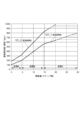
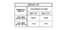
- FIG. 9 is a diagram showing an example of speed characteristics in a motor drive control device according to Embodiment 2; It is a figure which shows an example of a load determination table. It is a figure which shows an example of a load determination table. It is a figure which shows an example of a load determination table.
- FIG. 10 is a diagram showing the flow of processing in a first commutation control mode by the motor drive control device according to Embodiment 2;
- a motor drive control device (10, 10A) includes a control section ( 11, 11A), and a driving section (12) for driving the two-phase coils of the two-phase stepping motor based on the control signal.
- a first commutation control mode in which the coil is commutated according to a target energization time based on the current condition, and a second commutation control mode in which the coil is commutated based on the detection result of the zero cross point of the back electromotive voltage of the coil.
- control unit generates the control signal in the first commutation control mode when starting the two-phase stepping motor, and the detection result of the zero-crossing point satisfies a predetermined condition. and generating the control signal in the second commutation control mode.
- the commutation conditions include the speed of the two-phase stepping motor and one of the two-phase coils continuously in one direction.
- An energization angle ( ⁇ ) indicating a magnitude of an electrical angle of energization may be set, and the control unit may determine the target energization time based on the speed and the energization angle.
- the speed in the first commutation control mode may increase over time.
- the conduction angle in the first commutation control mode may decrease to a predetermined value over time.
- the control unit has a speed characteristic indicating a correspondence relationship between the drive amount of the two-phase stepping motor and the speed.
- Information (121) may be stored, and the control unit may determine the speed according to the drive amount based on the speed characteristics in the first commutation control mode.
- the control section (11A) controls the two-phase stepping motor in the first commutation control mode.
- the speed change rate may be determined based on the magnitude of the load on the two-phase stepping motor when the driving of the two-phase stepping motor is stopped immediately before.
- speed characteristics (121_1, 121_2) are stored, the plurality of speed characteristics are different in rate of change of the speed, and the control unit drives the two-phase stepping motor immediately before in the first commutation control mode.
- the speed characteristic may be selected such that the rate of change in the speed decreases as the load on the two-phase stepping motor increases when the stepping motor is stopped, and the speed may be determined based on the selected speed characteristic.
- control unit controls the speed and driving direction of the two-phase stepping motor when the driving of the two-phase stepping motor is stopped immediately before. You may estimate the magnitude
- the speed characteristic includes a first section (A) in which the speed changes at a constant rate and a rate greater than that of the first section.
- a second section (B) after the first section in which the speed changes in and a third section (C) after the second section in which the speed changes at a rate smaller than that in the second section; may include
- the predetermined condition includes a threshold value (125) relating to the number of times the zero-cross point is detected, and the control unit is configured to: The control mode may be switched from the first commutation control mode to the second commutation control mode when the number of times the zero-cross point is detected is equal to or greater than the threshold.
- a motor unit (1) according to a representative embodiment of the present invention comprises the motor drive control device (10) according to any one of [1] to [10] above, and the two-phase stepping and a motor (20).
- a motor drive control method for controlling the drive of a two-phase stepping motor according to a representative embodiment of the present invention is such that when starting the two-phase stepping motor, a preset commutation condition is met.
- FIG. 1 is a block diagram showing the configuration of a motor unit according to Embodiment 1.
- the motor unit 1 includes a two-phase stepping motor 20 and a motor drive control device 10 that drives the two-phase stepping motor 20 .
- the motor unit 1 can be applied to, for example, various devices using a motor as a power source, such as an actuator that can be used in HVAC (Heating Ventilation and Air-Conditioning) as an air conditioning unit for in-vehicle use.
- HVAC Heating Ventilation and Air-Conditioning
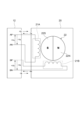
- FIG. 2 is a diagram schematically showing the configuration of the two-phase stepping motor 20 according to the first embodiment.
- the two-phase stepping motor 20 is, for example, a stepping motor having two-phase coils. As shown in FIG. 2, the two-phase stepping motor 20 has an A-phase coil 21A, a B-phase coil 21B, a rotor 22, and a two-phase stator yoke (not shown).
- the coils 21A and 21B are coils that excite a stator yoke (not shown).
- the coils 21A and 21B are each connected to a driving section 12 which will be described later. Different phase currents (coil currents) flow through the coils 21A and 21B.
- coil 21 when the coils 21A and 21B are not distinguished from each other, they may simply be referred to as "coil 21".
- the rotor 22 includes a permanent magnet magnetized with multiple poles so that the S poles 22S and the N poles 22N are alternately reversed along the circumferential direction.
- FIG. 2 the case where the rotor 22 has two poles is shown as an example.
- the stator yoke is arranged around the rotor 22 and close to the outer circumference of the rotor 22 .
- the rotor 22 rotates by periodically switching the phases of the coil currents flowing through the coils 21A and 21B.
- An output shaft (not shown) is connected to the rotor 22 , and the rotational force of the rotor 22 drives the output shaft.
- the motor drive control device 10 is a device for driving the two-phase stepping motor 20.
- the motor drive control device 10 controls the energization state of the coils 21A and 21B of each phase of the two-phase stepping motor 20 based on a drive command from, for example, a host device (not shown). controls the rotation and stopping of the .
- the motor drive control device 10 has a control section 11 and a drive section 12 .
- the drive unit 12 drives the two-phase stepping motor 20 by energizing the coils 21A and 21B of the two-phase stepping motor 20 .
- the driving section 12 has a motor driving section 13 .
- the motor drive unit 13 supplies drive power to the two-phase stepping motor 20 based on the control signal Sd generated by the control unit 11 .
- the motor drive unit 13 is connected to a positive terminal AP of the coil 21A, a negative terminal AN of the coil 21A, a positive terminal BP of the coil 21B, and a negative terminal BN of the coil 21B.
- the coils 21A and 21B are energized by applying a voltage to each terminal AP, AN, BP and BN.
- the motor drive unit 13 is configured by, for example, an H-bridge circuit (not shown) configured from four switching elements (for example, transistors).
- the motor drive unit 13 commutates the coils 21A and 21B by selectively turning ON/OFF each switching element forming the H bridge circuit, for example.
- the motor driving unit 13 applies, for example, a voltage of "+Va” across the terminals AN and AP of the coil 21A.
- the motor drive section 13 applies a voltage of "-Va” across the terminals AN and AP of the coil 21A.
- the motor drive unit 13 applies a voltage of “+Vb” across the terminals BN and BP of the coil 21B, for example, to turn on the B-phase coil 21B.
- the motor driving section 13 applies a voltage of "-Vb” across the terminal BN and the terminal BP of the coil 21B.
- the motor driving section 13 switches the voltage applied between the terminals of the coils 21A and 21B as described above, based on the control signal Sd for controlling the driving of the two-phase stepping motor 20, which is given from the control section 11. Thereby, the energization state (energization direction) of each coil 21A, 21B is switched to commutate each coil 21A, 21B.
- the control unit 11 is a functional unit that performs overall control of the motor drive control device 10 .
- the control unit 11 includes, for example, a processor such as a CPU, various storage devices such as RAM and ROM, peripherals such as a timer (counter), an A/D conversion circuit, a D/A conversion circuit, and an input/output I/F circuit.
- a program processing device for example, a microcontroller having a configuration in which circuits are connected to each other via a bus.
- the controller 11 is packaged as an IC (integrated circuit), but it is not limited to this.
- the control unit 11 performs commutation of the coils 21A and 21B according to a target energization time based on preset commutation conditions. It has a first commutation control mode and a second commutation control mode in which the coils 21A and 21B are commutated based on the detection results of the zero crossing points of the back electromotive voltages of the coils 21A and 21B.
- the control unit 11 In the first commutation control mode, the control unit 11 generates the control signal Sd so as to drive the two-phase stepping motor 20 by the two-phase excitation method or the 1-2 phase excitation method. In the second commutation control mode, the control unit 11 generates the control signal Sd to drive the two-phase stepping motor 20 by the 1-2 phase excitation method or the 1-phase excitation method.
- the controller 11 drives the two-phase stepping motor 20 by the 1-2 phase excitation method in the first commutation control mode and the second commutation control mode.
- the two-phase stepping motor starts to be driven, that is, immediately after the stopped two-phase stepping motor starts to be driven, if the load on the two-phase stepping motor is large, the coil is shifted with respect to the position of the rotor. Due to the delay in the excitation position, there is a possibility that the zero-crossing point of the back electromotive force cannot be detected at appropriate timing. If the zero-crossing point of the back electromotive voltage cannot be detected in the one-phase excitation method or the one-two phase excitation method, the energization of the coil cannot be appropriately switched, and the possibility of stepping out of the two-phase stepping motor increases.
- the control unit 11 sets the control mode to the first commutation control mode immediately after the start of driving the two-phase stepping motor 20, and Regardless of the point detection result, the coils 21A and 21B are commutated according to the target energization time based on the preset commutation conditions. is satisfied, the control mode is switched from the first commutation control mode to the second commutation control mode, and the coils 21A and 21B are commutated based on the detection result of the zero cross point of the back electromotive force of the coils 21A and 21B. .
- the predetermined condition includes, for example, a threshold regarding the number of times the zero-cross point of the back electromotive force is detected.
- the control unit 11 switches the control mode from the first commutation control mode to the second commutation control mode, for example, when the number of times of detection of the zero-cross points of the back electromotive force is equal to or greater than the threshold.
- the controller 11 has, as commutation conditions, the speed of the two-phase stepping motor 20 and an energization angle indicating the magnitude of the electrical angle at which one of the two-phase coils is continuously energized in one direction. , is set.
- the control unit 11 determines a target energization time based on the set speed and energization angle, and switches the energization of the coils 21A and 21B according to the target energization time.
- the target energization time is a target value for the length of the period during which one energization pattern (energization state) is to be continued.
- the control unit 11 sets the target energization time for 1-phase excitation and the target energization time for 2-phase excitation. 1-phase excitation and 2-phase excitation are alternately switched according to those target energization times. The details of the calculation method of the target energization time will be described later.
- the speed in the first commutation control mode is determined based on preset speed characteristics.
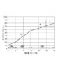
- FIG. 3 is a diagram showing an example of speed characteristics in the motor drive control device 10 according to Embodiment 1.
- FIG. 3 is a diagram showing an example of speed characteristics in the motor drive control device 10 according to Embodiment 1.
- the horizontal axis represents the drive amount of the two-phase stepping motor 20.
- the unit drive amount of the two-phase stepping motor 20 is set to one step.
- one step corresponds to an electrical angle of 90°, and driving the two-phase stepping motor 20 by four steps rotates by an electrical angle of 360°.
- the vertical axis represents the speed of the two-phase stepping motor 20 .
- the speed is the speed with which the two-phase stepping motor 20 is driven.
- the speed is, for example, the speed at which the coils 21A and 21B of the two-phase stepping motor are driven, that is, the speed (commutation speed) at which the excitation states (energization patterns) of the coils 21A and 21B are switched.
- the speed may be the rotation speed of the rotor of the two-phase stepping motor 20 .
- the vertical axis in FIG. 3 indicates the drive frequency [pps] converted to one phase as the speed of the two-phase stepping motor 20 .
- reference numeral 121 represents speed characteristics that indicate the correspondence between the drive amount and speed of the two-phase stepping motor 20 .
- the speed characteristic 121 is set such that the speed increases as the drive amount (number of steps) of the two-phase stepping motor 20 increases. In other words, in the first commutation control mode, the speed increases over time.
- the speed characteristic 121 includes a first section A in which the speed changes at a constant rate and a second section A after the first section A in which the speed changes at a higher rate than the first section A. It includes a segment B and a third segment C after the second segment B where the velocity changes at a smaller rate than the second segment B.
- the control unit 11 controls the commutation of the coils 21A and 21B while changing the speed (driving frequency) along the speed characteristics 121, for example. For example, as described above, stepping out is likely to occur immediately after the two-phase stepping motor 20 starts to operate. After that, when reaching a speed region where the possibility of occurrence of step-out is lowered, the control unit 11 increases the rate of speed change more than in the first interval A, as shown in the second interval B. FIG. When the zero-crossing point of the back electromotive force reaches a detectable speed region, the control unit 11 performs the following operations as shown in the third interval C to more reliably detect the zero-crossing point of the back electromotive force and avoid step-out.
- the first commutation control mode is switched to the second commutation control mode, and commutation is performed based on the detection result of the zero-cross point of the back electromotive voltage. control.
- the timings a, b, and c for switching from the first commutation control mode to the second commutation control mode change according to the load of the two-phase stepping motor 20.
- FIG. 3 Although the details will be described later, the greater the load, the faster the timing of switching from the first commutation control mode to the second commutation control mode. That is, the higher the load, the lower the speed at which the first commutation control mode switches to the second commutation control mode.
- FIG. 3 illustrates the speed characteristic 121 in which the speed changes in a polygonal line according to the driving amount, it is not limited to this.
- the speed characteristic may be such that the speed changes in a curve according to the driving amount.
- the conduction angle in the first commutation control mode is determined based on preset conduction angle characteristics.
- the relationship between the conduction angle and the excitation period in the two-phase stepping motor will be described.
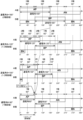
- FIG. 4 is a diagram for explaining the relationship between the conduction angle and the excitation period of the coils in the two-phase stepping motor.
- the horizontal axis represents the electrical angle.
- the excitation method of a two-phase stepping motor is determined by the energization angle ⁇ , which indicates the magnitude of the electrical angle at which one of the two-phase coils is continuously energized in one direction.
- the conduction angle ⁇ is set in the range of 90° ⁇ 180°
- the 1-2 phase excitation method is adopted, and one of the two phase coils 21 in the two-phase stepping motor 20 1-phase excitation that excites the coils 21 for two phases and two-phase excitation that excites the coils 21 for two phases out of the two-phase coils 21 are alternately repeated.
- the period of 1 phase excitation is 60°, and the period of 2 phase excitation is 30°, and when the conduction angle is 100°, the period of 1 phase excitation. is 80°, and the period of two-phase excitation is 10°. That is, the smaller the conduction angle ⁇ , the longer the one-phase excitation period and the shorter the two-phase excitation period. Also, the longer the two-phase excitation period is, the larger the torque of the two-phase stepping motor 20 becomes, and the more difficult it is to lose synchronism.
- the conduction angle ⁇ is decreased to the value set in the second commutation control mode over time.
- FIG. 5A and 5B are diagrams showing an example of conduction angle characteristics in the motor drive control device 10 according to Embodiment 1.
- FIG. 5A and 5B the horizontal axis represents the drive amount (number of steps) of the two-phase stepping motor 20, and the vertical axis represents the conduction angle ⁇ [degree].
- FIG. 5A shows a conduction angle characteristic 122_1 that indicates the correspondence relationship between the drive amount of the two-phase stepping motor 20 and the conduction angle when the two-phase stepping motor 20 is driven by the one-phase excitation method in the second commutation control mode. It is shown.
- 5B shows conduction angle characteristics showing the correspondence between the drive amount and the conduction angle of the two-phase stepping motor 20 when the two-phase stepping motor 20 is driven by the 1-2 phase excitation method in the second commutation control mode. 122_2 is shown.
- the conduction angle characteristics 122_1 and 122_2 are set so that the conduction angle decreases to a predetermined value (conduction angle in the second commutation control mode) as the drive amount (number of steps) of the two-phase stepping motor 20 increases. .
- the conduction angle decreases to a predetermined value over time.
- the 2-phase stepping motor 20 is driven by the 1-2 phase excitation method with ⁇ set to 150° (initial value). After that, the control unit 11 gradually decreases the conduction angle ⁇ from 150° according to an increase in the driving amount (the number of steps). When the driving amount (the number of steps) reaches "15", the conduction angle ⁇ is fixed at 90°, and the two-phase stepping motor 20 is driven by the one-phase excitation method.
- the control unit 11 sets the conduction angle ⁇ to a relatively large value, eg, 150° (initial value), and drives the two-phase stepping motor 20 by the 1-2 phase excitation method. After that, the control unit 11 gradually decreases the conduction angle ⁇ from 150° in accordance with an increase in the driving amount (the number of steps). When the driving amount (number of steps) reaches "15", the control unit 11 fixes the conduction angle ⁇ to 120° and drives the two-phase stepping motor 20 by the 1-2 phase excitation method with the conduction angle of 120°. .
- the conduction angle characteristics 122_1 and 122_2 may be referred to as "conduction angle characteristics 122".
- control section 11 performs commutation control of the coils 21A and 21B of the two-phase stepping motor 20 by switching between the two control modes described above.
- a specific functional block configuration of the control unit 11 for performing commutation control will be described below.
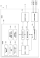
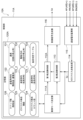
- FIG. 6 is a diagram showing an example of the functional block configuration of the control section 11 in the motor drive control device 10 according to Embodiment 1. As shown in FIG. For convenience of explanation, FIG. 6 shows the configuration for realizing the function of commutation control, and the illustration of the configuration related to other functions is omitted.
- control unit 11 includes, for example, a control mode determination unit 111, a first commutation control unit 112, a second commutation control unit 113, a zero cross point detection unit 114, a back electromotive voltage monitoring unit 115, a control It has a signal generation unit 116 and a storage unit 120 .
- These functional units are, for example, a program processing device (microcontroller) as the control unit 11 described above. It is realized by controlling the circuit.
- microcontroller program processing device
- the back electromotive voltage monitoring unit 115 is a functional unit that monitors the back electromotive force generated in the coils 21A and 21B of each phase.
- the zero-cross point detection unit 114 is a functional unit for detecting the zero-cross points of the back electromotive force generated in the coils 21A and 21B of the two-phase stepping motor 20 based on the monitoring result of the back electromotive force monitoring unit 115.
- the zero-crossing point detection unit 114 outputs a detection signal Sz indicating that the zero-crossing point has been detected when the zero-crossing point of the back electromotive force of the non-excited coil 21 is detected.
- the storage unit 120 is a functional unit for storing various data necessary for performing energization switching control.
- the storage unit 120 stores, for example, information on the speed characteristics 121 and the conduction angle characteristics 122 described above, and information on a threshold value (zero-cross detection threshold value) 125 regarding the number of times the back electromotive force zero-cross point is detected as the predetermined condition. ing.
- the storage unit 120 also stores information on the number of zero-crossing point detections (zero-crossing detection count value) 124 of the back electromotive force detected by the zero-crossing point detection unit 114 .
- the drive amount of the two-phase stepping motor 20, that is, the number of steps 126 is stored in the storage unit 120 .
- the storage unit 120 may store both the conduction angle characteristics 122_1 and 122_2. Only the characteristic 122 may be stored in the storage unit 120 .
- the control signal generation section 116 is a functional section that generates a control signal Sd for controlling the driving of the two-phase stepping motor 20 .
- the control signal generation unit 116 generates a control signal Sd according to instructions from the first commutation control unit 112 and the second commutation control unit 113 to be described later, and supplies the control signal Sd to the drive unit 12 .
- the control signal Sd is, for example, a PWM (Pulse Width Modulation) signal.
- the control mode determination unit 111 is a functional unit that determines the control mode for controlling the commutation of the coils 21A and 21B of the two-phase stepping motor 20. For example, when an instruction to drive the two-phase stepping motor 20 is received from a higher-level device (not shown), the control mode determining unit 111 starts counting the number of steps (driving amount), and sets the value to the step number 126 in the storage unit 120. , selects either the first commutation control mode or the second commutation control mode, and instructs the first commutation control unit 112 or the second commutation control unit 113 to execute commutation control. do.
- the control mode determination unit 111 selects the first commutation control mode, and instructs the first commutation control unit 112 to Instructs execution of commutation control.
- the second commutation control unit 113 has stopped commutation control.
- the control mode determination unit 111 monitors whether or not the zero cross point of the back electromotive force of the coil 21 is detected by the zero cross point detection unit 114 during the period of the first commutation control mode.
- the control mode determining unit 111 counts the number of times the zero cross point of the back electromotive force of the coil 21 is detected during the period of the first commutation control mode, and stores the value as the zero cross detection count value 124 in the storage unit 120. .
- the control mode determination unit 111 compares the zero-cross detection count value 124 and the zero-cross detection threshold value 125 during the period of the first commutation control mode, and when the zero-cross detection count value 124 is equal to or greater than the zero-cross detection threshold value 125, the control is performed.
- the mode is switched from the first commutation control mode to the second commutation control mode to instruct the first commutation control unit 112 to stop the commutation control, and the second commutation control unit 113 to be commutated. Instructs execution of flow control.
- the first commutation control section 112 is a functional section that performs commutation control of the coils 21A and 21B of the two-phase stepping motor 20 in the first commutation control mode.
- the first commutation control unit 112 starts commutation control in the first commutation control mode when the control mode determination unit 111 instructs execution of commutation control.
- the first commutation control unit 112 determines the speed corresponding to the number of steps 126 at that time based on the speed characteristics 121 stored in the storage unit 120 . Also, the first commutation control unit 112 determines the conduction angle ⁇ corresponding to the number of steps 126 at that time based on the conduction angle characteristic 122 stored in the storage unit 120 .
- the first commutation control unit 112 calculates a target energization time for one-phase excitation and a target energization time for two-phase excitation based on the determined speed and energization angle ⁇ . Based on this, an instruction to switch the energization is output to the control signal generation unit 116 .
- the angle corresponding to the period of one-phase excitation and the angle corresponding to the period of two-phase excitation are determined. Therefore, for example, by dividing the angle corresponding to the period of one-phase excitation by the speed, the target energization time of one-phase excitation can be obtained. Similarly, by dividing the angle corresponding to the period of the two-phase excitation by the speed, the target energization time of the two-phase excitation can be obtained.
- the first commutation control unit 112 uses the above-described method to determine the target energization time for 1-phase excitation based on the speed and conduction angle ⁇ determined according to the number of steps 126 at that time. is calculated, time measurement is started, and the control signal generator 116 is instructed to perform one-phase excitation.
- the first commutation control unit 112 performs 2-phase excitation based on the speed and energization angle ⁇ determined according to the number of steps 126 at that time. , and starts measuring the time, and instructs the control signal generator 116 to perform two-phase excitation.
- the first commutation control unit 112 executes the above process for performing one-phase excitation again.
- the first commutation control unit 112 determines the speed (driving frequency) and the conduction angle ⁇ for each number of steps based on the speed characteristics 121 and the conduction angle characteristics 122, and based on the determined speed and conduction angle ⁇ target energization times for one-phase excitation and two-phase excitation, respectively, and commutation of the coils 21A and 21B is controlled based on the calculated target energization times.
- the second commutation control section 113 is a functional section that performs commutation control of the coils 21A and 21B of the two-phase stepping motor 20 in the second commutation control mode.
- the second commutation control unit 113 performs commutation control in the second commutation control mode (commutation control based on the detection result of the zero cross point of the back electromotive voltage) when the control mode determination unit 111 instructs execution of commutation control. control). For example, consider the case where the two-phase stepping motor 20 is driven by the 1-2 phase excitation method in the second commutation control mode.
- the second commutation control unit 113 instructs the control signal generation unit 116 to perform the one-phase excitation, and causes the zero-cross point detection unit 114 to detect the zero-cross point of the back electromotive force. Monitor for presence.
- the zero-crossing point detector 114 detects the zero-crossing point of the back electromotive force during the one-phase excitation period
- the second commutation controller 113 instructs the control signal generator 116 to perform two-phase excitation. .
- the second commutation control unit 113 sets, for example, the elapsed time per unit angle when the two-phase stepping motor 20 is being excited (for example, the period of one-phase excitation) and the set conduction angle ⁇ (for example, In the case of FIG. 5B, 120°), a target energization time for performing two-phase excitation is calculated, and when the target energization time has passed, the excitation state of the two-phase stepping motor 20 is changed from two-phase excitation to The control signal generator 116 is instructed to switch to 1-phase excitation.
- the second commutation control unit 113 controls the commutation of the coils 21A and 21B based on the detection result of the zero-cross point of the back electromotive force of the coil 21 in the second commutation control mode.
- the energization of the coil 21 can be switched at an appropriate speed according to the magnitude of the load on the phase stepping motor 20 . As a result, even when the load of the two-phase stepping motor 20 fluctuates, it is possible to drive the two-phase stepping motor 20 more stably while avoiding step-out.
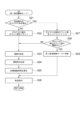
- FIG. 7 is a flow chart showing the flow of commutation control according to the first embodiment.
- the first commutation control mode is set in the control unit 11 as the initial setting of the control mode after the power of the motor drive control device 10 is turned on or the driving of the two-phase stepping motor 20 is stopped. shall be
- the control unit 11 first starts counting the number of steps (driving amount) and changes the value to the number of steps. 126 is stored in the storage unit 120, and it is determined whether or not the control mode is the second commutation control mode (step S1).
- control mode is set to the first commutation control mode when starting the motor drive control device 10 (step S1: NO)
- the control unit 11 controls the two-phase stepping motor 20 in the first commutation control mode. is controlled (step S2).
- step S1 When the control mode is the second commutation control mode (step S1: YES), the control unit 11 performs drive control of the two-phase stepping motor 20 in the second commutation control mode (step S3).
- the control unit 11 determines whether or not an instruction to stop driving the two-phase stepping motor 20 has been received from a host device or the like (step S4).
- the control unit 11 stops the two-phase stepping motor 20 when receiving the instruction to stop driving (step S ⁇ b>4 : YES).
- step S4: NO the control unit 11 returns to step S1 again to continue driving control of the two-phase stepping motor 20.
- step S2 the flow of processing (step S2) in the first commutation control mode will be described.
- FIG. 8 is a diagram showing the flow of processing (step S2) in the first commutation control mode by the motor drive control device 10 according to the first embodiment.
- the control mode determination unit 111 of the control unit 11 determines whether or not the zero cross point of the back electromotive force of the coil 21 is detected by the zero cross point detection unit 114 (step S21). When the zero-crossing point of the back electromotive voltage is not detected (step S21: NO), the control mode determination unit 111 resets the zero-crossing detection count value 124 (step S22).
- the first commutation control unit 112 of the control unit 11 determines the speed (step S23). Specifically, the first commutation control unit 112 determines the speed corresponding to the number of steps 126 at that time based on the speed characteristic 121 by the method described above.
- the first commutation control unit 112 determines the conduction angle ⁇ (step S24). Specifically, the first commutation control unit 112 determines the conduction angle ⁇ corresponding to the number of steps 126 at that time based on the conduction angle characteristic 122 by the method described above.
- the first commutation control unit 112 uses the method described above to determine the target of the next one-phase excitation or two-phase excitation based on the speed determined in step S23 and the conduction angle ⁇ determined in step S24.
- the energization time is determined (step S25).
- the first commutation control unit 112 instructs the control signal generation unit 116 to perform commutation based on the target energization time determined in step S25 (step S26). After that, the control unit 11 returns to the processing flow of FIG. 7 described above.
- step S21 when the zero-crossing point of the back electromotive force is detected (step S21: YES), the control mode determining unit 111 increments the zero-crossing detection count value 124 by +1 (step S27).
- control mode determination unit 111 determines whether or not the zero-cross detection count value 124 is equal to or greater than the zero-cross detection threshold 125 (step S28). If the zero-cross detection count value 124 is less than the zero-cross detection threshold value 125 (step S28: NO), the control mode determination unit 111 proceeds to step S23, and determines the speed and conduction angle corresponding to the current step number 126. Along with determining ⁇ , a target energization time for the next one-phase excitation or two-phase excitation is set, and a commutation instruction is issued to the control signal generator 116 (steps S23 to S26).
- step S28 when the zero-crossing detection count value 124 is equal to or greater than the zero-crossing detection threshold value 125 in step S28 (step S28: YES), the control mode determination unit 111 changes the control mode from the first commutation control mode to the second commutation control mode. mode (step S29). Specifically, the control mode determination unit 111 instructs the first commutation control unit 112 to stop the commutation control in the first commutation control mode, and instructs the second commutation control unit 113 to perform the commutation control in the first commutation control mode. It instructs execution of commutation control in the 2 commutation control mode.
- step S3 the flow of processing (step S3) in the second commutation control mode will be described.
- FIG. 9 is a diagram showing the flow of processing (step S2) in the second commutation control mode by the motor drive control device 10 according to the first embodiment.
- the second commutation control unit 113 determines whether or not the zero-crossing point of the back electromotive force of the coil 21 has been detected by the zero-crossing point detection unit 114 (step S31).
- step S31 YES
- the second commutation control unit 113 performs 1-2 phase excitation based on the detection result of the zero-crossing point of the back electromotive force by the above-described method.
- the commutation control is performed according to the method (or the one-phase excitation method) (step S32). After that, the control unit 11 returns to the processing flow of FIG. 7 described above.
- step S31 determines that an abnormality has occurred, and notifies the higher-level device of the occurrence (step S33).
- the motor drive control device 10 performs commutation control of the two-phase stepping motor 20 according to the above-described processing procedure.
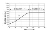
- FIG. 10 is a diagram showing an example of speed change after the two-phase stepping motor 20 starts to be driven.
- the horizontal axis represents the drive amount (number of steps) of the two-phase stepping motor 20
- the vertical axis represents the drive frequency [pps] as the speed of the coils 21A and 21B.
- Reference numeral 401 denotes a speed ratio with respect to the drive amount (number of steps) of the two-phase stepping motor after the motor drive control device 10 starts driving the two-phase stepping motor when the magnitude of the load is 5.5 L [Ncm]. represents change.
- the control unit 11 When starting to drive the two-phase stepping motor 20, the control unit 11 starts commutation control of the two-phase stepping motor 20 in the first commutation control mode as described above, and as shown in FIG. As the drive amount (number of steps) of the phase stepping motor 20 increases, the speed (driving frequency) is increased.
- the control unit 11 When the number of times the zero-crossing point of the back electromotive force of the coil 21 is detected becomes equal to or greater than the threshold value (the zero-crossing detection count value 124 is equal to or greater than the zero-crossing detection threshold value 125) during the period of the first commutation control mode, the control unit 11 The control mode is switched from the first commutation control mode to the second commutation control mode, and commutation control is started based on the detection result of the zero-cross point of the back electromotive force. In the second commutation control mode, the speed is constant when the load on the two-phase stepping motor 20 is constant.
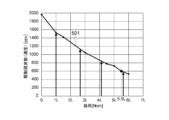
- FIG. 11 is a diagram showing an example of changes in speed with respect to the load of the two-phase stepping motor 20.
- the horizontal axis represents the load magnitude [Ncm] of the two-phase stepping motor 20, and the vertical axis represents the driving frequency [pps] as the speed of the coils 21A and 21B.
- Reference numeral 501 denotes speed change with respect to load change of the two-phase stepping motor 20 when the two-phase stepping motor 20 is driven by the 1-2 phase excitation method in the second commutation control mode by the motor drive control device 10. represents.
- reference numeral 501 represents the speed (driving frequency) at which the first commutation control mode is switched to the second commutation control mode with respect to the load.
- the timing at which the zero-cross point of the back electromotive voltage is detected during the period changes according to the magnitude of the load. Specifically, as shown in FIG. 11, the speed (driving frequency) at which the first commutation control mode is switched to the second commutation control mode decreases as the load increases.
- the timing at which the first commutation control mode is switched to the second commutation control mode also depends on the load. Change. For example, as shown in FIG. 11, when the magnitude of the load is 5.5 L [Ncm], the speed when the two-phase stepping motor 20 is driven by the 1-2 phase excitation method in the second commutation control mode is 600 [pps]. Therefore, as shown in FIG. 10, when the magnitude of the load is 5.5 L [Ncm], the control mode is changed to the second commutation control mode when the speed reaches 600 [pps] in the first commutation control mode. When switching to the commutation control mode and the load is constant at 5.5 L [Ncm], the speed stabilizes at 600 [pps].
- the motor drive control device 10 controls the coil 21A according to the target energization time based on the preset commutation conditions in the first commutation control mode immediately after starting the two-phase stepping motor 20.
- 21B are commutated, and when the detection result of the zero cross point of the back electromotive force of the coil 21 satisfies a predetermined condition, the coil is commutated based on the detection result of the zero cross point of the back electromotive force in the second commutation control mode.
- 21A and 21B are commutated.
- the target energization time is determined immediately after the start of the two-phase stepping motor 20, even if the back electromotive force is small or the zero cross point of the back electromotive force cannot be detected at an appropriate timing.
- the two-phase stepping motor 20 can be properly driven. As a result, even when the load on the two-phase stepping motor 20 is large, it is possible to prevent the two-phase stepping motor 20 from stepping out immediately after the two-phase stepping motor 20 is started.
- the commutation conditions are the speed of the two-phase stepping motor and the energization angle indicating the magnitude of the electrical angle at which one of the two-phase coils is continuously energized in one direction.
- angle ⁇ is set.
- the motor drive control device 10 determines a target energization time based on the speed and the energization angle ⁇ . According to this, the target energization time in the first commutation control mode can be easily calculated.
- the motor drive control device 10 changes the control mode from the first commutation control mode to the second commutation control mode when the number of times the counter-electromotive voltage zero-cross point is detected exceeds the threshold value during the first commutation control mode. switch to mode. According to this, the control mode is switched from the first commutation control mode to the second commutation control mode in a state where the zero-crossing point of the back electromotive force can be stably detected. It is possible to more reliably avoid the occurrence of stepping out immediately after the start, and to drive the two-phase stepping motor 20 stably.
- the speed increases over time. According to this, as described above, by driving the two-phase stepping motor 20 at a low speed immediately after the start of driving the two-phase stepping motor 20, the occurrence of step-out is suppressed, and the speed is increased with the lapse of time. As a result, the two-phase stepping motor 20 can reach the target drive state quickly.
- the conduction angle ⁇ decreases to a predetermined value over time.
- the two-phase excitation period is set long to drive the two-phase stepping motor 20, thereby suppressing the occurrence of step-out.
- the two-phase excitation period becomes shorter and the one-phase excitation period becomes longer, so that the two-phase stepping motor 20 can reach the target driving state quickly.
- control unit 11 of the motor drive control device 10 stores information of speed characteristics 121 indicating the correspondence relationship between the drive amount and the speed of the two-phase stepping motor 20, and the control unit 11 operates in the first commutation control mode. , the speed corresponding to the driving amount is determined based on the speed characteristic 121 . This makes it easy to change the speed over time after the two-phase stepping motor 20 starts to drive.
- the speed characteristic 121 includes a first section A in which the speed changes at a constant rate and a second section A after the first section A in which the speed changes at a higher rate than the first section A. 2 segments B and a third segment C after the second segment B where the speed changes at a smaller rate than the second segment B. According to this, it is possible to more reliably avoid the occurrence of step-out immediately after the start of driving of the two-phase stepping motor 20, and allow the two-phase stepping motor 20 to reach the target driving state more quickly. .
- FIG. 12 is a diagram showing an example of the functional block configuration of the control section 11A in the motor drive control device 10A according to the second embodiment.
- the motor drive control device 10A according to the second embodiment is similar to the first embodiment in that it switches the speed characteristics used at the start of driving based on the magnitude of the load at the time when the driving of the two-phase stepping motor 20 is stopped immediately before. It differs from the motor drive control device 10 and is the same as the motor drive control device 10 according to the first embodiment in other respects.
- the control unit 11A controls the two-phase stepping motor 20 to stop driving immediately before. Based on the load magnitude of 20, the rate of change in speed is determined.
- the control mode determination unit 111A of the control unit 11A increases the load on the two-phase stepping motor 20 immediately before stopping the driving of the two-phase stepping motor 20.
- a speed characteristic 121 with a small rate of change in speed is selected, and the speed is determined based on the selected speed characteristic 121 .
- FIG. 13 is a diagram showing an example of speed characteristics 121_1 and 121_2 in the motor drive control device 10A according to the second embodiment.
- the horizontal axis represents the drive amount (number of steps) of the two-phase stepping motor 20, and the vertical axis represents the drive frequency [pps] as the speed of the coils 21A and 21B.
- the controller 11A stores a plurality of pieces of speed characteristic 121 information indicating the relationship between the drive amount (the number of steps) of the two-phase stepping motor 20 corresponding to the magnitude of the load on the two-phase stepping motor 20 and the speed.
- a speed characteristic 121_1 corresponding to a high load and a speed characteristic 121_2 corresponding to a low load are stored in the storage unit 120A.
- the two speed characteristics 121_1 and 121_2 are different in speed change rate. For example, in the speed characteristic 121_2 corresponding to low load, the speed changes faster than the speed characteristic 121_1 corresponding to high load, and the control mode is switched from the first commutation control mode to the second commutation control mode more quickly. can be done.
- speed characteristics 121_1 and speed characteristics 121_2 are referred to as speed characteristics 121 when they are not distinguished from each other.
- the first commutation control unit 112A of the control unit 11A adjusts the load of the two-phase stepping motor 20 when the drive of the two-phase stepping motor 20 is stopped immediately before. determine the size.
- the control mode determination unit 111A of the control unit 11A stores the speed value when the two-phase stepping motor 20 is being driven in the storage unit 120A as the speed information 131, and periodically updates it.
- the control mode determination unit 111A stores the rotation direction of the two-phase stepping motor 20 as the drive direction information 132 in the storage unit 120A, and periodically updates the information.
- the speed information 131 and driving direction information 132 may be, for example, the rotational speed and rotational direction information of the output shaft of the two-phase stepping motor 20 .
- the control mode determination unit 111A of the control unit 11 detects information on the rotation speed of the output shaft detected by the detection device and the rotation speed of the output shaft.
- Direction information may be acquired and stored as speed information 131 and driving direction information 132 in the storage unit 120A.
- the speed information 131 and the driving direction information 132 are sequentially updated while the two-phase stepping motor 20 is being driven, and the latest values are stored in the storage unit 120A. For example, when the control unit 11 stops driving the two-phase stepping motor 20 according to an instruction from a higher-level device or the like, information about the speed and driving direction immediately before the two-phase stepping motor 20 stops driving is stored in the storage unit 120A.
- the speed information 131 and the driving direction information 132 may be erased when the power supply to the motor drive control device 10A (control section 11A) is stopped, or the speed information 131 and the driving direction information 131 may be stored in the nonvolatile memory. information 132 may be stored so as not to be erased regardless of the presence or absence of power supply.
- the first commutation control unit 112A When starting to drive the two-phase stepping motor 20 in the first commutation control mode, the first commutation control unit 112A changes the load of the two-phase stepping motor 20 when the driving of the two-phase stepping motor 20 is stopped immediately before.
- the magnitude is determined based on at least one of speed information 131 and drive direction information 132 stored in storage unit 120A.
- the first commutation control unit 112A uses the load determination table 133, which is information stored in advance in the storage unit 120A and which indicates the correspondence relationship between at least one of the speed and driving direction and the magnitude of the load, to determine the load. determine the size of the load.
- FIGS. 14A to 14C are diagrams showing examples of load determination tables.
- FIG. 14A shows a load determination table 133 showing the correspondence relationship between speed and load magnitude.
- FIGS. 14B and 14C show a load determination table 133 showing the correspondence between speed and drive direction and load magnitude.
- the first commutation control unit 112A uses the load determination table 133 shown in FIG. It is determined whether or not the speed R stored in 120A is greater than the threshold value Rth. When the speed R is smaller than the threshold value Rth (R ⁇ Rth), it is determined that the load of the two-phase stepping motor 20 is "high load", and the speed characteristic 121_1 corresponding to "high load” is selected. On the other hand, when the speed R is equal to or greater than the threshold value Rth (R ⁇ Rth), it is determined that the load of the two-phase stepping motor 20 is "low load", and the speed characteristic 121_2 corresponding to "low load” is selected. .
- the first commutation control unit 112A calculates speed information 131 and driving direction information 132 based on the load determination table 133 shown in FIG. 14B. is used to determine the magnitude of the load on the two-phase stepping motor 20 .
- the speed R is smaller than the threshold value Rth (R ⁇ Rth), and the driving direction of the two-phase stepping motor 20 at the start of driving coincides with the driving direction at the time of immediate stop stored in the storage unit 120A.
- the first commutation control unit 112A determines that the load of the two-phase stepping motor 20 is "high load”, Select the speed characteristic 121_1 corresponding to “high load”.
- the speed R is equal to or greater than the threshold value Rth (R ⁇ Rth), and the driving direction of the two-phase stepping motor 20 at the start of driving coincides with the driving direction at the time of immediate stop stored in the storage unit 120A (driving the driving direction at the time of start is the same direction as that at the time of stopping the driving immediately before), the first commutation control unit 112A determines that the load of the two-phase stepping motor 20 is “low load”, Select the speed characteristic 121_2 corresponding to "load”.
- the speed R is smaller than the threshold value Rth (R ⁇ Rth), and the driving direction of the two-phase stepping motor 20 at the start of driving does not match the driving direction at the time of immediate stop stored in the storage unit 120A (driving start the driving direction at the time of stopping the driving is opposite to that at the time of stopping the driving immediately before), the first commutation control unit 112A determines that the load of the two-phase stepping motor 20 is “low load”, and determines that the load of the two-phase stepping motor 20 is “low ” is selected.
- the speed R is equal to or greater than the threshold value Rth (R ⁇ Rth), and the driving direction of the two-phase stepping motor 20 at the start of driving does not match the driving direction at the time of immediate stop stored in the storage unit 120A (driving If the drive direction at the start is opposite to that at the time the drive was stopped just before), the first commutation control unit 112A determines that the load of the two-phase stepping motor 20 is “high load”, and determines that the load of the two-phase stepping motor 20 is “high load” Select the speed characteristic 121_1 corresponding to "load”.
- the first commutation control unit 112A obtains speed information 131 and driving direction information 132 based on the load determination table 133 shown in FIG. 14C. is used to determine the magnitude of the load on the two-phase stepping motor 20 .
- the speed R is smaller than the threshold value Rth (R ⁇ Rth), and the driving direction of the two-phase stepping motor 20 at the start of driving coincides with the driving direction at the time of immediate stop stored in the storage unit 120A.
- the first commutation control unit 112A determines that the load of the two-phase stepping motor 20 is "high load”, Select the speed characteristic 121_1 corresponding to “high load”.
- the speed R is equal to or greater than the threshold value Rth (R ⁇ Rth), and the driving direction of the two-phase stepping motor 20 at the start of driving coincides with the driving direction at the time of immediate stop stored in the storage unit 120A (at the time of starting driving). is the same direction as when the drive was stopped immediately before), the first commutation control unit 112A determines that the load of the two-phase stepping motor 20 is "low load”, and determines that the load is "low load”. select the velocity characteristic 121_2 corresponding to .
- the driving direction of the two-phase stepping motor 20 at the start of driving does not match the driving direction at the time of immediately preceding stop stored in the storage unit 120A (the driving direction at the time of starting driving is opposite to the direction at the time of immediately stopping driving).
- the first commutation control unit 112A determines that the load of the two-phase stepping motor 20 is “unknown” regardless of the speed (the magnitude of the speed R and the threshold value Rth). In this case, the first commutation control unit 112A selects the speed characteristic 121_1 corresponding to "high load".
- the actual load of the two-phase stepping motor 20 is determined to be "high” by selecting the speed characteristic 121_1 corresponding to "high load”. Regardless of whether the load is “low load” or “low load”, by reducing the rate of change in speed, it is possible to avoid the occurrence of stepping out immediately after the start of driving of the two-phase stepping motor 20, thereby stabilizing the two-phase stepping motor 20. can be driven.
- An example of the load determination method has been described above with reference to FIGS. 14A, 14B, and 14C, but depending on the object to be controlled, a method other than the above may be used for load determination.
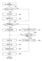
- FIG. 15 is a diagram showing the flow of processing in the first commutation control mode by the motor drive control device 10A according to the second embodiment.
- the motor drive control device 10A according to the second embodiment performs commutation control according to the flowchart shown in FIG. 7 in the same manner as the motor drive control device 10 according to the first embodiment. , the process shown in FIG. 15 is performed.
- control mode determination unit 111A sets the control mode to the first commutation control mode, similar to the motor drive control device 10 according to the first embodiment.
- the first commutation control unit 112A determines whether or not the speed characteristic 121 corresponding to the load has been determined (step S41). If the speed characteristic corresponding to the load has already been determined (step S41: YES), the first commutation control unit 112A proceeds to step S21, and performs the processing flow (FIG. 8) according to the first embodiment. Commutation control is performed according to the same procedure (steps S21 to S29).
- the first commutation control unit 112A controls the load of the two-phase stepping motor 20.
- the size is estimated (step S42). Specifically, the first commutation control unit 112A performs the above-described method based on at least one of the speed information 131 and the driving direction information 132 stored in the storage unit 120A and the load determination table 133.
- the magnitude of the load on the two-phase stepping motor 20 is estimated by the following.
- the first commutation control unit 112A selects one of the speed characteristics 121_1 and 121_2 based on the magnitude of the load estimated in step S42 (step S43).
- the first commutation control unit 112A uses the speed characteristic 121 selected in step S43 to perform commutation control (steps S21 to S29).
- the motor drive control device 10A when the motor drive control device 10A according to the second embodiment starts the commutation control of the two-phase stepping motor 20 in the first commutation control mode, when the driving of the two-phase stepping motor 20 is stopped immediately before The rate of speed change is determined based on the magnitude of the load on the two-phase stepping motor 20 of . Specifically, the motor drive control device 10A stores a plurality of speed characteristics 121_1 and 121_2 having different rates of speed change in the storage unit 120A, and stops driving the two-phase stepping motor 20 immediately before. The speed characteristic 121 having a smaller rate of speed change is selected as the load at the time increases, and commutation control is performed in the first commutation control mode.
- the two-phase stepping motor 20 can be driven at an appropriate speed according to the load of the two-phase stepping motor 20. That is, when the load of the two-phase stepping motor 20 is "high load”, commutation control is performed using the speed characteristic 121_1 in which the speed changes gradually, thereby avoiding step-out at high load. As a result, the two-phase stepping motor 20 can be driven more stably. On the other hand, when the load of the two-phase stepping motor 20 is "low load”, step-out is less likely to occur than in the case of "high load”. By performing flow control, it is possible to quickly reach the target driving state of the two-phase stepping motor 20 .
- the motor drive control device 10A controls the two-phase stepping motor 20 based on at least one information of the speed and driving direction of the two-phase stepping motor 20 when the drive of the two-phase stepping motor 20 is stopped immediately before.
- the magnitude of the load on the stepping motor 20 is estimated. This makes it possible to accurately and easily estimate the magnitude of the load on the two-phase stepping motor 20 .
- the two-phase stepping motor 20 is driven by the 1-2 phase excitation method in the first commutation control mode and the second commutation control mode was exemplified, but the present invention is not limited to this.
- the 2-phase stepping motor 20 may be driven by the 1-2 phase excitation method in the first commutation control mode, and the 2-phase stepping motor 20 may be driven by the 1-phase excitation method in the second commutation control mode.
- 5A and 5B illustrate the case where the initial value of the conduction angle ⁇ in the conduction angle characteristics 122_1 and 122_2 is set to 150°, but the initial value of the conduction angle can be arbitrarily set within the range of 90° ⁇ ⁇ ⁇ 180°. Configurable. For example, when it is desired to avoid step-out more reliably, the initial value of the energization angle ⁇ is set to 180°, the two-phase stepping motor 20 is started to be driven by the two-phase excitation method, and then the energization angle ⁇ is set to 180°. It may be lowered to switch to the 1-2 phase excitation method.
- the initial value of the conduction angle ⁇ is set to, for example, 120°, and the conduction angle ⁇ may be decreased from 120°.
- the conduction angle ⁇ may be set to a fixed value (the same value as in the second commutation control mode) and only the speed may be changed.
- the rotor 22 has two poles, but the number of poles of the rotor 22 is not particularly limited.
- the motor unit 1 is not limited to the configuration disclosed in FIG.
- the drive section 12 may have a current detection circuit or the like for detecting coil currents of the coils 21A and 21B in addition to the motor drive section 13 described above.
Landscapes
- Engineering & Computer Science (AREA)
- Power Engineering (AREA)
- Control Of Stepping Motors (AREA)
- Control Of Motors That Do Not Use Commutators (AREA)
Abstract
Description
2相ステッピングモータの駆動方式としては、1相励磁方式、2相励磁方式、1-2相励磁方式が知られている。
先ず、本願において開示される発明の代表的な実施の形態について概要を説明する。なお、以下の説明では、一例として、発明の構成要素に対応する図面上の参照符号を、括弧を付して記載している。
以下、本発明の実施の形態の具体例について図を参照して説明する。なお、以下の説明において、各実施の形態において共通する構成要素には同一の参照符号を付し、繰り返しの説明を省略する。
図1は、実施の形態1に係るモータユニットの構成を示すブロック図である。
図1に示すように、モータユニット1は、2相ステッピングモータ20と、2相ステッピングモータ20を駆動するモータ駆動制御装置10とを備えている。モータユニット1は、例えば、車載用途の空調ユニットとしてのHVAC(Heating Ventilation and Air-Conditioning)で使用可能なアクチュエータ等のモータを動力源として用いる各種装置に適用可能である。
駆動部12は、2相ステッピングモータ20のコイル21A,21Bに通電して、2相ステッピングモータ20を駆動する。駆動部12は、モータ駆動部13を有している。
本実施の形態において、2相ステッピングモータ20の単位駆動量を1ステップとする。例えば、1ステップは電気角90°分に相当し、2相ステッピングモータ20を4ステップ分駆動すると、電気角は360°回転する。
速度は、2相ステッピングモータ20の駆動に関する速度である。速度は、例えば、2相ステッピングモータのコイル21A,21Bを駆動する速度、すなわち、コイル21A、21Bの励磁状態(通電パターン)を切り替える速度(転流速度)である。なお、速度は、2相ステッピングモータ20のロータの回転速度であってもよい。図3の縦軸には、2相ステッピングモータ20の速度として、1相換算の駆動周波数〔pps〕が示されている。
例えば、上述したように2相ステッピングモータ20の起動開始直後は脱調が発生し易いため、制御部11は、先ず、第1区間Aに示すように、速度を緩やかに上昇させる。その後、脱調の発生する可能性が低下する速度領域に到達したら、制御部11は、第2区間Bに示すように、第1区間Aよりも速度の変化の割合を上げる。逆起電圧のゼロクロス点が検出可能な速度領域に到達したら、逆起電圧のゼロクロス点をより確実に検出して脱調を回避するために、制御部11は、第3区間Cに示すように、再び速度の変化の割合を下げる。その後、逆起電圧のゼロクロス点の検出結果が所定の条件を満たした場合に、第1転流制御モードから第2転流制御モードに切り替え、逆起電圧のゼロクロス点の検出結果に基づく転流制御を行う。
ここで、2相ステッピングモータにおける通電角と励磁期間との関係について説明する。
図4において、横軸は電気角を表している。同図の上側から1段目には通電角θ=180°としたときのA相およびB相のコイルの励磁状態がそれぞれ示され、同図の上側から二段目には通電角θ=120°としたときのA相およびB相のコイルの励磁状態がそれぞれ示され、同図の上側から三段目には通電角θ=100°としたときのA相およびB相のコイルの励磁状態がそれぞれ示され、同図の上側から4段目には通電角θ=90°としたときのA相およびB相のコイルの励磁状態がそれぞれ示されている。
図5Aおよび図5Bにおいて、横軸は2相ステッピングモータ20の駆動量(ステップ数)を表し、縦軸は、通電角θ〔degree〕を表している。図5Aには、第2転流制御モードにおいて1相励磁方式によって2相ステッピングモータ20を駆動する場合における、2相ステッピングモータ20の駆動量と通電角との対応関係を示す通電角特性122_1が示されている。図5Bには、第2転流制御モードにおいて1-2相励磁方式によって2相ステッピングモータ20を駆動する場合における、2相ステッピングモータ20の駆動量と通電角との対応関係を示す通電角特性122_2が示されている。
なお、以下の説明において、通電角特性122_1,122_2を区別しない場合には、「通電角特性122」と表記する場合がある。
なお、説明の便宜上、図6には転流制御の機能を実現するための構成が図示され、その他の機能に関する構成の図示を省略している。
例えば、第2転流制御モードにおいて、1-2相励磁方式によって2相ステッピングモータ20を駆動する場合を考える。
以下の説明において、例えば、モータ駆動制御装置10の電源投入後または2相ステッピングモータ20の駆動停止後において、制御部11には、制御モードの初期設定として第1転流制御モードが設定されるものとする。
図10において、横軸は2相ステッピングモータ20の駆動量(ステップ数)を表し、縦軸は、コイル21A,21Bの速度としての駆動周波数〔pps〕を表している。参照符号401は、負荷の大きさが5.5L〔Ncm〕である場合における、モータ駆動制御装置10による2相ステッピングモータの駆動開始後の2相ステッピングモータの駆動量(ステップ数)に対する速度の変化を表している。
図11において、横軸は2相ステッピングモータ20の負荷の大きさ〔Ncm〕を表し、縦軸は、コイル21A,21Bの速度としての駆動周波数〔pps〕を表している。参照符号501は、モータ駆動制御装置10による第2転流制御モードにおいて1-2相励磁方式によって2相ステッピングモータ20を駆動しているときの2相ステッピングモータ20の負荷の変化に対する速度の変化を表している。言い換えると、符号501は、負荷に対する、第1転流制御モードから第2転流制御モードに切り替わる速度(駆動周波数)を表している。
例えば、図11に示すように、負荷の大きさが5.5L〔Ncm〕である場合、第2転流制御モードにおいて1-2相励磁方式によって2相ステッピングモータ20を駆動した場合の速度は600〔pps〕となる。したがって、図10に示すように、負荷の大きさが5.5L〔Ncm〕である場合には、第1転流制御モードにおいて速度が600〔pps〕に到達したときに、制御モードが第2転流制御モードに切り替え、負荷の大きさが5.5L〔Ncm〕で一定であれば、速度は600〔pps〕で安定する。
これによれば、2相ステッピングモータ20の起動開始直後には、目標通電時間が決められているので、逆起電圧が小さい場合や逆起電圧のゼロクロス点が適切なタイミングにおいて検出できない場合であっても、2相ステッピングモータ20を適切に駆動することができる。これにより、2相ステッピングモータ20の負荷が大きい場合であっても、2相ステッピングモータ20の起動直後における2相ステッピングモータ20の脱調の発生を抑制することが可能となる。
これによれば、第1転流制御モードにおける目標通電時間を容易に算出することができる。
これによれば、逆起電圧のゼロクロス点が安定して検出できるようになった状態において制御モードが第1転流制御モードから第2転流制御モードに切り替わるので、2相ステッピングモータ20の駆動開始直後における脱調の発生をより確実に回避し、2相ステッピングモータ20の安定した駆動が可能となる。
これによれば、上述したように、2相ステッピングモータ20の駆動開始直後には低い速度で2相ステッピングモータ20を駆動することにより脱調の発生を抑制しつつ、時間の経過とともに速度を上げることにより、2相ステッピングモータ20を目標とする駆動状態まで速やかに到達させることが可能となる。
これによれば、上述したように、2相ステッピングモータ20の駆動開始直後には2相励磁の期間を長く設定して2相ステッピングモータ20を駆動することにより脱調の発生を抑制しつつ、時間の経過とともに2相励磁の期間が短くなり、1相励磁の期間が長くなることにより、2相ステッピングモータ20を目標とする駆動状態まで速やかに到達させることが可能となる。
これによれば、2相ステッピングモータ20の駆動開始後に、時間の経過とともに速度を変化させることが容易となる。
これによれば、2相ステッピングモータ20の駆動開始直後における脱調の発生をより確実に回避しつつ、2相ステッピングモータ20を目標とする駆動状態まで、より速やかに到達させることが可能となる。
図12は、実施の形態2に係るモータ駆動制御装置10Aにおける制御部11Aの機能ブロック構成の一例を示す図である。
図13において、横軸は2相ステッピングモータ20の駆動量(ステップ数)を表し、縦軸は、コイル21A,21Bの速度としての駆動周波数〔pps〕を表している。
そこで、例えば、制御部11Aの制御モード決定部111Aは、2相ステッピングモータ20を駆動しているときの速度の値を、速度の情報131として記憶部120Aに記憶し、定期的に更新する。
図14Aには、速度と負荷の大きさとの対応関係を示す負荷判定テーブル133が示されている。図14Bおよび図14Cには、速度および駆動方向と負荷の大きさとの対応関係を示す負荷判定テーブル133が示されている。
以上、図14A、図14B、および図14Cを用いて、負荷判定方法の一例を説明したが、制御対象物によっては、負荷判定に上記以外の方法を用いることもあり得る。
これによれば、2相ステッピングモータ20の負荷の大きさを、正確且つ容易に推定することが可能となる。
以上、本発明者によってなされた発明を実施の形態に基づいて具体的に説明したが、本発明はそれに限定されるものではなく、その要旨を逸脱しない範囲において種々変更可能であることは言うまでもない。
例えば、より確実に脱調を回避したい場合には、通電角θの初期値を180°に設定して、2相励磁方式によって2相ステッピングモータ20の駆動を開始し、その後、通電角θを低下させて1-2相励磁方式に切り替えてもよい。また、2相ステッピングモータ20の駆動開始後に、より速やかに2相ステッピングモータ20を目標とする駆動状態に遷移させたい場合には、通電角θの初期値を例えば120°に設定し、通電角θを120°から低下させてもよい。あるいは、通電角θを固定値(第2転流制御モードと同じ値)に設定し、速度のみを変化させてもよい。
Claims (12)
- 2相ステッピングモータの駆動を制御するための制御信号を生成する制御部と、
前記制御信号に基づいて、前記2相ステッピングモータの2相のコイルを駆動する駆動部と、を備え、
前記制御部は、制御モードとして、予め設定された転流条件に基づく目標通電時間にしたがって前記コイルの転流を行う第1転流制御モードと、前記コイルの逆起電圧のゼロクロス点の検出結果に基づいて前記コイルの転流を行う第2転流制御モードと、を有し、
前記制御部は、前記2相ステッピングモータの起動開始時には、前記第1転流制御モードにおいて前記制御信号を生成し、前記ゼロクロス点の検出結果が所定の条件を満たした場合に、前記第2転流制御モードにおいて前記制御信号を生成する
モータ駆動制御装置。 - 請求項1に記載のモータ駆動制御装置において、
前記転流条件として、前記2相ステッピングモータの速度と、前記2相のコイルのうち一つの相のコイルを一方向に連続して通電する電気角の大きさを示す通電角と、が設定され、
前記制御部は、前記第1転流制御モードにおいて、前記速度と前記通電角とに基づいて前記目標通電時間を決定する
モータ駆動制御装置。 - 請求項2に記載のモータ駆動制御装置において、
前記第1転流制御モードにおける前記速度は、時間の経過とともに高くなる
モータ駆動制御装置。 - 請求項2または3に記載のモータ駆動制御装置において、
前記第1転流制御モードにおける前記通電角は、時間の経過とともに所定値まで低下する
モータ駆動制御装置。 - 請求項2乃至4の何れか一項に記載のモータ駆動制御装置において、
前記制御部には、前記2相ステッピングモータの駆動量と前記速度との対応関係を示す速度特性の情報が記憶され、
前記制御部は、前記第1転流制御モードにおいて、前記速度特性に基づいて、前記駆動量に応じた前記速度を決定する
モータ駆動制御装置。 - 請求項2乃至4の何れか一項に記載のモータ駆動制御装置において、
前記制御部は、前記第1転流制御モードにおいて前記2相ステッピングモータの転流制御を開始する場合に、直前に前記2相ステッピングモータの駆動を停止したときの前記2相ステッピングモータの負荷の大きさに基づいて、前記速度の変化の割合を決定する
モータ駆動制御装置。 - 請求項6に記載のモータ駆動制御装置において、
前記制御部には、前記2相ステッピングモータの負荷の大きさに対応する前記2相ステッピングモータの駆動量と前記速度との関係を示す速度特性の情報が複数記憶され、
複数の前記速度特性は、互いに前記速度の変化の割合が相違し、
前記制御部は、前記第1転流制御モードにおいて、直前に前記2相ステッピングモータの駆動を停止したときの前記2相ステッピングモータの負荷が大きいほど、前記速度の変化の割合が小さい前記速度特性を選択し、選択した前記速度特性に基づいて前記速度を決定する
モータ駆動制御装置。 - 請求項6または7に記載のモータ駆動制御装置において、
前記制御部は、直前に前記2相ステッピングモータの駆動を停止したときの前記2相ステッピングモータの前記速度と駆動方向の少なくとも一つの情報に基づいて、前記負荷の大きさを推定する
モータ駆動制御装置。 - 請求項5または7に記載のモータ駆動制御装置において、
前記速度特性は、前記速度が一定の割合で変化する第1区間と、前記第1区間よりも大きい割合で前記速度が変化する前記第1区間の後の第2区間と、前記第2区間よりも小さい割合で前記速度が変化する前記第2区間の後の第3区間と、を含む
モータ駆動制御装置。 - 請求項1乃至9の何れか一項に記載のモータ駆動制御装置において、
前記所定の条件は、前記ゼロクロス点の検出回数に関する閾値を含み、
前記制御部は、前記ゼロクロス点の検出回数が前記閾値以上となった場合に、前記制御モードを前記第1転流制御モードから前記第2転流制御モードに切り替える
モータ駆動制御装置。 - 請求項1乃至10の何れか一項に記載のモータ駆動制御装置と、
前記2相ステッピングモータと、を備える
モータユニット。 - 2相ステッピングモータの駆動を制御するためのモータ駆動制御方法であって、
前記2相ステッピングモータの起動開始時に、予め設定された転流条件に基づく目標通電時間にしたがって前記2相ステッピングモータの2相のコイルの転流を行う第1ステップと、
前記コイルの逆起電圧のゼロクロス点の検出結果が所定の条件を満たしているか否かを判定する第2ステップと、
前記ゼロクロス点の検出結果が所定の条件を満たしている場合に、前記ゼロクロス点の検出結果に基づいて前記コイルの転流を行う第3ステップと、を含む
モータ駆動制御方法。
Priority Applications (2)
| Application Number | Priority Date | Filing Date | Title |
|---|---|---|---|
| US18/712,823 US20250023496A1 (en) | 2021-12-03 | 2022-10-27 | Motor drive control device, motor unit, and motor drive control method |
| CN202280076051.5A CN118251830A (zh) | 2021-12-03 | 2022-10-27 | 马达驱动控制装置、马达单元以及马达驱动控制方法 |
Applications Claiming Priority (2)
| Application Number | Priority Date | Filing Date | Title |
|---|---|---|---|
| JP2021-196737 | 2021-12-03 | ||
| JP2021196737A JP7724702B2 (ja) | 2021-12-03 | 2021-12-03 | モータ駆動制御装置、モータユニット、およびモータ駆動制御方法 |
Publications (1)
| Publication Number | Publication Date |
|---|---|
| WO2023100549A1 true WO2023100549A1 (ja) | 2023-06-08 |
Family
ID=86611847
Family Applications (1)
| Application Number | Title | Priority Date | Filing Date |
|---|---|---|---|
| PCT/JP2022/040076 Ceased WO2023100549A1 (ja) | 2021-12-03 | 2022-10-27 | モータ駆動制御装置、モータユニット、およびモータ駆動制御方法 |
Country Status (4)
| Country | Link |
|---|---|
| US (1) | US20250023496A1 (ja) |
| JP (1) | JP7724702B2 (ja) |
| CN (1) | CN118251830A (ja) |
| WO (1) | WO2023100549A1 (ja) |
Citations (2)
| Publication number | Priority date | Publication date | Assignee | Title |
|---|---|---|---|---|
| JP2005278320A (ja) * | 2004-03-25 | 2005-10-06 | Koyo Seiko Co Ltd | ブラシレスモータの起動方法、ブラシレスモータの制御装置及び電動ポンプ |
| JP2018038213A (ja) * | 2016-09-01 | 2018-03-08 | ミネベアミツミ株式会社 | モータ駆動制御装置およびモータ駆動制御方法 |
Family Cites Families (2)
| Publication number | Priority date | Publication date | Assignee | Title |
|---|---|---|---|---|
| US4103216A (en) * | 1976-05-28 | 1978-07-25 | Tally Corporation | Stepping motor closed loop constant velocity control system |
| JP2019216499A (ja) * | 2018-06-11 | 2019-12-19 | 日本電産サンキョー株式会社 | ブラシレスdcモータの制御方法及び制御装置 |
-
2021
- 2021-12-03 JP JP2021196737A patent/JP7724702B2/ja active Active
-
2022
- 2022-10-27 CN CN202280076051.5A patent/CN118251830A/zh active Pending
- 2022-10-27 US US18/712,823 patent/US20250023496A1/en active Pending
- 2022-10-27 WO PCT/JP2022/040076 patent/WO2023100549A1/ja not_active Ceased
Patent Citations (2)
| Publication number | Priority date | Publication date | Assignee | Title |
|---|---|---|---|---|
| JP2005278320A (ja) * | 2004-03-25 | 2005-10-06 | Koyo Seiko Co Ltd | ブラシレスモータの起動方法、ブラシレスモータの制御装置及び電動ポンプ |
| JP2018038213A (ja) * | 2016-09-01 | 2018-03-08 | ミネベアミツミ株式会社 | モータ駆動制御装置およびモータ駆動制御方法 |
Also Published As
| Publication number | Publication date |
|---|---|
| CN118251830A (zh) | 2024-06-25 |
| US20250023496A1 (en) | 2025-01-16 |
| JP7724702B2 (ja) | 2025-08-18 |
| JP2023082798A (ja) | 2023-06-15 |
Similar Documents
| Publication | Publication Date | Title |
|---|---|---|
| JP4050489B2 (ja) | モータの制御方法 | |
| US7235941B2 (en) | Phase commutation method of brushless direct current motor | |
| JP3698051B2 (ja) | モータ駆動装置 | |
| JP6173107B2 (ja) | ブラシレスモータの駆動装置、及び駆動方法 | |
| JP2005057922A (ja) | ブラシレスモータ及びブラシレスモータの駆動方法 | |
| JP2020198750A (ja) | ブラシレスdcモータの制御方法及び制御装置 | |
| JP5745955B2 (ja) | 駆動装置、及び駆動方法 | |
| JP7724702B2 (ja) | モータ駆動制御装置、モータユニット、およびモータ駆動制御方法 | |
| JP7550719B2 (ja) | モータ駆動制御装置、モータユニット、およびモータ駆動制御方法 | |
| US11139763B2 (en) | Motor drive control device, motor unit, and motor drive control method | |
| JP2023084894A (ja) | モータ駆動制御装置、モータユニット、およびモータ駆動制御方法 | |
| JP2009171738A (ja) | モータ駆動装置 | |
| JP7770251B2 (ja) | モータ駆動制御装置、モータユニット、およびモータ駆動制御方法 | |
| JP6375758B2 (ja) | モータ制御装置およびそれを用いた空気調和機 | |
| US11831270B2 (en) | Motor drive control device, motor unit, and motor drive control method | |
| WO2023228945A1 (ja) | モータ駆動制御装置、モータユニット、およびモータ駆動制御方法 | |
| US11515814B2 (en) | Motor drive control device and method for controlling the same | |
| KR19990075671A (ko) | 오픈루프 구간의 제어방법 | |
| KR20090008944A (ko) | 무정류자 직류 모터용 구동 장치 및 방법 | |
| JP2021027747A (ja) | モータ駆動制御装置、モータユニット、およびモータ駆動制御方法 | |
| JP2008043073A (ja) | ブラシレスモータの回転数制御方法、ブラシレスモータの回転数制御装置 | |
| JP2025158294A (ja) | モータ駆動装置、送風機、モータ駆動装置の制御方法 | |
| JP2023131436A (ja) | モータ駆動制御装置、モータユニット、およびモータ駆動制御方法 | |
| JP2025112854A (ja) | モータ駆動制御装置、アクチュエータ、およびモータ駆動制御方法 |
Legal Events
| Date | Code | Title | Description |
|---|---|---|---|
| 121 | Ep: the epo has been informed by wipo that ep was designated in this application |
Ref document number: 22900982 Country of ref document: EP Kind code of ref document: A1 |
|
| WWE | Wipo information: entry into national phase |
Ref document number: 202280076051.5 Country of ref document: CN |
|
| WWE | Wipo information: entry into national phase |
Ref document number: 18712823 Country of ref document: US |
|
| NENP | Non-entry into the national phase |
Ref country code: DE |
|
| 122 | Ep: pct application non-entry in european phase |
Ref document number: 22900982 Country of ref document: EP Kind code of ref document: A1 |