WO2023100341A1 - 車体フレームの前部構造 - Google Patents
車体フレームの前部構造 Download PDFInfo
- Publication number
- WO2023100341A1 WO2023100341A1 PCT/JP2021/044416 JP2021044416W WO2023100341A1 WO 2023100341 A1 WO2023100341 A1 WO 2023100341A1 JP 2021044416 W JP2021044416 W JP 2021044416W WO 2023100341 A1 WO2023100341 A1 WO 2023100341A1
- Authority
- WO
- WIPO (PCT)
- Prior art keywords
- vehicle
- width direction
- frame
- vehicle width
- bulkhead
- Prior art date
- Legal status (The legal status is an assumption and is not a legal conclusion. Google has not performed a legal analysis and makes no representation as to the accuracy of the status listed.)
- Ceased
Links
Images





Classifications
-
- B—PERFORMING OPERATIONS; TRANSPORTING
- B62—LAND VEHICLES FOR TRAVELLING OTHERWISE THAN ON RAILS
- B62D—MOTOR VEHICLES; TRAILERS
- B62D21/00—Understructures, i.e. chassis frame on which a vehicle body may be mounted
- B62D21/02—Understructures, i.e. chassis frame on which a vehicle body may be mounted comprising longitudinally or transversely arranged frame members
Definitions
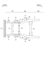
- the rear area RA where the cabin is mounted is wider in the vehicle width direction than the front area FA where the engine is mounted.
- the width is gradually widened in the vehicle width direction between the area RA and the area RA.
- An engine mount 11, a strut tower 12, and a bump stopper bracket 13 projecting outward in the vehicle width direction are provided in the front area FA, and an area MA extending from the front area FA to the rear area RA projects outward in the vehicle width direction.
- a cab mount bracket 14 is provided.
- the strut tower 12 is configured to protrude in the height direction of the vehicle, and accommodates a shock absorber (not shown) and a coil spring (not shown).
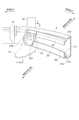
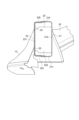
- the bulkhead 23 has a leg portion joined to the side wall on the inner side in the vehicle width direction of the side frame 2, and a contact surface joined to the side wall on the outer side in the vehicle width direction.
- the leg portion 232 is joined to the side wall 21 a of the inner frame 21 and the contact surface 231 is joined to the side wall 22 a of the outer frame 22 .
- the bulkhead 23 overlaps the vehicle height direction upper portion of the bump stopper bracket 13 in the vehicle longitudinal direction
- the reinforcement 25 overlaps the vehicle height direction lower portion of the bump stopper bracket 13 in the vehicle longitudinal direction.
- the front structure of the vehicle body frame (1) according to the aspect [1] is provided as a pair of left and right side frames (2, 2) that are spaced apart in the vehicle width direction and extend along the vehicle front-rear direction. ), strut towers (12) respectively provided at vehicle front portions of the pair of side frames (2, 2), and strut towers (12) located in the vicinity of the rear in the vehicle front-rear direction of the strut tower (12) along the vehicle width direction.
- a vehicle body frame (1) front structure according to another aspect is the vehicle body frame (1) front structure according to [2], wherein the bulkhead (23) includes the side frame ( 2), the leg portion (232) is joined to the side wall on the inner side in the vehicle width direction, and the contact surface (231) is joined to the side wall on the outer side in the vehicle width direction.
- a vehicle body frame (1) front structure is the vehicle body frame (1) front structure according to [4], wherein the rear end of the bulkhead (23) in the vehicle longitudinal direction is , and front ends of the reinforcements (24, 25) in the vehicle front-rear direction are provided so as to overlap with the connecting portion of the cross member (32) to the side frame (2) when viewed in the vehicle width direction.
- a vehicle body frame (1) front structure is the vehicle body frame (1) front structure according to any one of [1] to [7], comprising: (2) includes an inner frame (21) forming the side wall on the inner side in the vehicle width direction and an outer frame (22) forming the side wall on the outer side in the vehicle width direction, the inner frame (21) comprising: The outer frame (22) has upper and lower walls (21b, 21c) extending outward in the vehicle width direction from the upper and lower ends of the side walls, and has a concave cross section with the outer side in the vehicle width direction open.
Landscapes
- Engineering & Computer Science (AREA)
- Chemical & Material Sciences (AREA)
- Combustion & Propulsion (AREA)
- Transportation (AREA)
- Mechanical Engineering (AREA)
- Body Structure For Vehicles (AREA)
Abstract
Description
11 エンジンマウント
12 ストラットタワー
13 バンプストッパブラケット
14 キャブマウントブラケット
15 バンパリンフォース
2 サイドフレーム
2B 傾斜部
21 インナフレーム
21a 側壁
21b,21c 上下壁
21d ランス
21d1 端面
22 アウタフレーム
22a 側壁
22b,22c 上下壁
22b1 端面
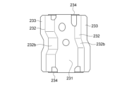
23 バルクヘッド
231 当接面
232 脚部
232a 凹部
232b 傾斜部
233 フランジ
234 フラップ
24,25 リンフォース
31, クロスメンバ
31,32 クロスメンバ(サスペンションクロスメンバ)
FA 前部領域
RA 後部領域
MA 前部領域から後部領域に至る領域
Claims (9)
- 車幅方向に間隔を空けて左右一対で設けられ、車両前後方向に沿って延びる中空形状の一対のサイドフレームと、
前記一対のサイドフレームの車両前部にそれぞれ設けられるストラットタワーと、
前記ストラットタワーの車両前後方向後方近傍に位置して車幅方向に沿って延び、前記一対のサイドフレーム間を連結するクロスメンバと、
を備えた車体フレームの前部構造であって、
前記サイドフレームは、その内部に、車幅方向に対向する側壁間を長手方向の一定の範囲に亘って補強するバルクヘッドを有し、
前記クロスメンバは、前記ストラットタワーから車両後方に所定の間隔を空けた位置で前記サイドフレームに結合され、
前記バルクヘッドは、車幅方向から見て前記クロスメンバの前記サイドフレームとの結合部に重ねて配置される
車体フレームの前部構造。 - 前記バルクヘッドは、前記サイドフレームの車幅方向の何れか一方の前記側壁の内面に対向する当接面と、前記当接面から前記サイドフレームの車幅方向の他方に延びて他方側の前記側壁に接合される脚部と、を有する、
請求項1に記載の車体フレームの前部構造。 - 前記バルクヘッドは、前記サイドフレームの車幅方向内側の前記側壁に前記脚部が接合され、車幅方向外側の前記側壁に前記当接面が接合される、
請求項2に記載の車体フレームの前部構造。 - 前記サイドフレームは、その内部において同サイドフレームの車幅方向外側の前記側壁の内面に接合され、前記バルクヘッドの近傍から車両前後方向後方に向かって前記側壁の内面に沿って延びるリンフォースを備える、
請求項1から3のいずれか一項に記載の車体フレームの前部構造。 - 前記バルクヘッドの車両前後方向後端と、前記リンフォースの車両前後方向前端とが、車幅方向から見て、前記クロスメンバの前記サイドフレームとの結合部と重なるよう設けられる、
請求項4に記載の車体フレームの前部構造。 - 前記サイドフレームは、前記クロスメンバの車両後方で車幅方向外側に傾斜される傾斜部を有し、
前記リンフォースは、前記傾斜部まで延びている
請求項4または5に記載の車体フレームの前部構造。 - 前記サイドフレームの車幅方向外側の前記側壁から車幅方向外側に突設され、サスペンションアームの上方への移動を規制するバンプストッパブラケットを備え、
前記バルクヘッドは、車幅方向から見て、前記バンプストッパブラケットと重なる位置に配置される、
請求項4から6のいずれか一項に記載の車体フレームの前部構造。 - 前記バンプストッパブラケットは、車幅方向から見て、前記バルクヘッドおよび前記リンフォースの両者に跨って重なるよう設けられる
請求項7に記載の車体フレームの前部構造。 - 前記サイドフレームは、車幅方向内側の前記側壁を構成するインナフレームと、車幅方向外側の前記側壁を構成するアウタフレームと、を含み、
前記インナフレームは、前記側壁の上下端から車幅方向外側に延びる上下壁を有して、前記車幅方向外側が開放された断面凹状を成し、前記アウタフレームは、前記側壁の上下端から車幅方向内側に延びる上下壁を有して前記車幅方向内側が開放された断面凹状を成し、
前記サイドフレームは、前記インナフレームの上下壁と前記アウタフレームの上下壁とがそれぞれ重ね合わされて筒状に構成され、
前記バルクヘッドは、前記インナフレームと前記アウタフレームの車幅方向の間隔を規定する、
請求項1から7のいずれか一項に記載の車体フレームの前部構造。
Priority Applications (2)
| Application Number | Priority Date | Filing Date | Title |
|---|---|---|---|
| JP2023564690A JP7790445B2 (ja) | 2021-12-03 | 2021-12-03 | 車体フレームの前部構造 |
| PCT/JP2021/044416 WO2023100341A1 (ja) | 2021-12-03 | 2021-12-03 | 車体フレームの前部構造 |
Applications Claiming Priority (1)
| Application Number | Priority Date | Filing Date | Title |
|---|---|---|---|
| PCT/JP2021/044416 WO2023100341A1 (ja) | 2021-12-03 | 2021-12-03 | 車体フレームの前部構造 |
Publications (1)
| Publication Number | Publication Date |
|---|---|
| WO2023100341A1 true WO2023100341A1 (ja) | 2023-06-08 |
Family
ID=86611769
Family Applications (1)
| Application Number | Title | Priority Date | Filing Date |
|---|---|---|---|
| PCT/JP2021/044416 Ceased WO2023100341A1 (ja) | 2021-12-03 | 2021-12-03 | 車体フレームの前部構造 |
Country Status (2)
| Country | Link |
|---|---|
| JP (1) | JP7790445B2 (ja) |
| WO (1) | WO2023100341A1 (ja) |
Citations (7)
| Publication number | Priority date | Publication date | Assignee | Title |
|---|---|---|---|---|
| JPS5211715U (ja) * | 1975-07-11 | 1977-01-27 | ||
| JP2003252234A (ja) * | 2002-03-05 | 2003-09-10 | Toyota Motor Corp | 車体前部構造 |
| JP2010047114A (ja) * | 2008-08-21 | 2010-03-04 | Mazda Motor Corp | 自動車のフレーム構造 |
| JP2015166207A (ja) * | 2014-03-03 | 2015-09-24 | トヨタ自動車株式会社 | 車両骨格構造 |
| JP2018047714A (ja) * | 2016-09-20 | 2018-03-29 | スズキ株式会社 | 車体構造 |
| JP2019089411A (ja) * | 2017-11-13 | 2019-06-13 | スズキ株式会社 | 車体構造 |
| US20200262491A1 (en) * | 2019-02-18 | 2020-08-20 | GM Global Technology Operations LLC | Body rocker, battery cross-bar, and body cross-bar configuration for load distribution between vehicle body and under-vehicle battery |
-
2021
- 2021-12-03 WO PCT/JP2021/044416 patent/WO2023100341A1/ja not_active Ceased
- 2021-12-03 JP JP2023564690A patent/JP7790445B2/ja active Active
Patent Citations (7)
| Publication number | Priority date | Publication date | Assignee | Title |
|---|---|---|---|---|
| JPS5211715U (ja) * | 1975-07-11 | 1977-01-27 | ||
| JP2003252234A (ja) * | 2002-03-05 | 2003-09-10 | Toyota Motor Corp | 車体前部構造 |
| JP2010047114A (ja) * | 2008-08-21 | 2010-03-04 | Mazda Motor Corp | 自動車のフレーム構造 |
| JP2015166207A (ja) * | 2014-03-03 | 2015-09-24 | トヨタ自動車株式会社 | 車両骨格構造 |
| JP2018047714A (ja) * | 2016-09-20 | 2018-03-29 | スズキ株式会社 | 車体構造 |
| JP2019089411A (ja) * | 2017-11-13 | 2019-06-13 | スズキ株式会社 | 車体構造 |
| US20200262491A1 (en) * | 2019-02-18 | 2020-08-20 | GM Global Technology Operations LLC | Body rocker, battery cross-bar, and body cross-bar configuration for load distribution between vehicle body and under-vehicle battery |
Also Published As
| Publication number | Publication date |
|---|---|
| JPWO2023100341A1 (ja) | 2023-06-08 |
| JP7790445B2 (ja) | 2025-12-23 |
Similar Documents
| Publication | Publication Date | Title |
|---|---|---|
| CN103635377B (zh) | 车辆的前部车身结构 | |
| CN107054470B (zh) | 车身前部构造 | |
| JP5924308B2 (ja) | 車体前部構造 | |
| EP1990261A1 (en) | Rear structure of vehicle body | |
| US20110175401A1 (en) | Lower Structure of Vehicle Body Rear Portion | |
| US11661021B2 (en) | Vehicle body front structure | |
| CN109421816B (zh) | 车体构造 | |
| US11242091B2 (en) | Vehicle body front structure | |
| CN103998328B (zh) | 车辆前部结构 | |
| CN109421815B (zh) | 车体构造 | |
| JP6020530B2 (ja) | 車両骨格構造 | |
| CN111746647B (zh) | 车辆用副车架 | |
| JP2921183B2 (ja) | 自動車の前部車体構造 | |
| CN110884567B (zh) | 车辆的前部车身结构 | |
| CN110356351B (zh) | 车辆的保险杠装置 | |
| WO2023100341A1 (ja) | 車体フレームの前部構造 | |
| JP2022036512A (ja) | 車体前部構造 | |
| JP5234324B2 (ja) | 車両の車体構造 | |
| JP2015145240A (ja) | 車両端部構造 | |
| JP7246836B2 (ja) | 車両前部構造 | |
| US20250115203A1 (en) | Vehicle impact absorbing structure | |
| JP6597673B2 (ja) | 車両の前部車体構造 | |
| US20250115301A1 (en) | Vehicle impact absorbing structure | |
| JP7067254B2 (ja) | 車体前部構造 | |
| JP7518479B2 (ja) | 車台のフレーム構造 |
Legal Events
| Date | Code | Title | Description |
|---|---|---|---|
| 121 | Ep: the epo has been informed by wipo that ep was designated in this application |
Ref document number: 21966422 Country of ref document: EP Kind code of ref document: A1 |
|
| WWE | Wipo information: entry into national phase |
Ref document number: 2023564690 Country of ref document: JP |
|
| WWE | Wipo information: entry into national phase |
Ref document number: 2401002807 Country of ref document: TH |
|
| NENP | Non-entry into the national phase |
Ref country code: DE |
|
| 122 | Ep: pct application non-entry in european phase |
Ref document number: 21966422 Country of ref document: EP Kind code of ref document: A1 |