WO2023095408A1 - 情報生成システム、情報生成方法及びコンピュータプログラム - Google Patents
情報生成システム、情報生成方法及びコンピュータプログラム Download PDFInfo
- Publication number
- WO2023095408A1 WO2023095408A1 PCT/JP2022/032541 JP2022032541W WO2023095408A1 WO 2023095408 A1 WO2023095408 A1 WO 2023095408A1 JP 2022032541 W JP2022032541 W JP 2022032541W WO 2023095408 A1 WO2023095408 A1 WO 2023095408A1
- Authority
- WO
- WIPO (PCT)
- Prior art keywords
- link
- intersection
- cycle length
- route
- inflow
- Prior art date
- Legal status (The legal status is an assumption and is not a legal conclusion. Google has not performed a legal analysis and makes no representation as to the accuracy of the status listed.)
- Ceased
Links
Images


Classifications
-
- G—PHYSICS
- G01—MEASURING; TESTING
- G01C—MEASURING DISTANCES, LEVELS OR BEARINGS; SURVEYING; NAVIGATION; GYROSCOPIC INSTRUMENTS; PHOTOGRAMMETRY OR VIDEOGRAMMETRY
- G01C21/00—Navigation; Navigational instruments not provided for in groups G01C1/00 - G01C19/00
- G01C21/26—Navigation; Navigational instruments not provided for in groups G01C1/00 - G01C19/00 specially adapted for navigation in a road network
- G01C21/34—Route searching; Route guidance
-
- G—PHYSICS
- G08—SIGNALLING
- G08G—TRAFFIC CONTROL SYSTEMS
- G08G1/00—Traffic control systems for road vehicles
- G08G1/01—Detecting movement of traffic to be counted or controlled
-
- G—PHYSICS
- G08—SIGNALLING
- G08G—TRAFFIC CONTROL SYSTEMS
- G08G1/00—Traffic control systems for road vehicles
- G08G1/09—Arrangements for giving variable traffic instructions
Definitions
- the present disclosure relates to an information generation system, an information generation method, and a computer program.
- This application claims priority based on Japanese application No. 2021-192837 filed on November 29, 2021, and incorporates all the descriptions described in the Japanese application.
- Patent Document 1 in order to generate a travel time with higher accuracy, each incoming link entering a node at one end of a link or each outgoing link exiting from a node at the other end of a link is calculated. Techniques for calculating the average value and standard deviation of time are disclosed.
- the information generation system of the present disclosure includes a generation unit that generates a travel time of a link that enters from a first intersection and exits at a second intersection adjacent to the first intersection, and the generation unit generates a travel time at the first intersection.
- a generation unit that generates a travel time of a link that enters from a first intersection and exits at a second intersection adjacent to the first intersection, and the generation unit generates a travel time at the first intersection.
- the information generation method of the present disclosure includes a generation step of generating a travel time of a link entering from a first intersection and exiting at a second intersection adjacent to the first intersection, wherein the generation step includes: When the absolute value of the difference between the first cycle length of the provided traffic signal and the second cycle length of the traffic signal provided at the second intersection is equal to or less than a predetermined value, for each inflow road to the link a first step of generating a plurality of types of travel times of the link for each outflow route from the link or for each combination of an inflow route to the link and an outflow route from the link; When the absolute value of the difference between the length and the second cycle length is greater than the predetermined value, one type of travel time for the link is generated regardless of the inflow path to the link and the outflow path from the link. and a second step to generate information.
- a computer program causes a computer to execute a generation step of generating a travel time of a link entering from a first intersection and exiting at a second intersection adjacent to the first intersection, wherein the generation step includes: When the absolute value of the difference between the first cycle length of the traffic signal installed at one intersection and the second cycle length of the traffic signal installed at the second intersection is less than or equal to a predetermined value, a first step of generating a plurality of types of travel times of the link for each inflow path, each outflow path from the link, or for each combination of inflow path to the link and outflow path from the link; When the absolute value of the difference between the first cycle length and the second cycle length is greater than the predetermined value, the travel time of the link regardless of the inflow path to the link and the outflow path from the link and a second step of generating one type.
- FIG. 1 is a schematic diagram illustrating an information generation system according to an embodiment.
- FIG. 2 is a block diagram illustrating the functional configuration of a processing unit according to the embodiment;
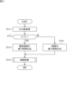
- FIG. 3 is a flow chart illustrating the order of an information generation method according to an embodiment.
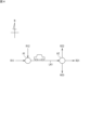
- FIG. 4 is a schematic diagram illustrating a link and its surroundings according to the embodiment.
- FIG. 5 is a table illustrating travel times according to the embodiment.
- FIG. 6 is a table illustrating travel times according to the embodiment.
- FIG. 7 is a subroutine illustrating the details of the route search step according to the embodiment.
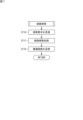
- FIG. 8 is a flowchart illustrating the order of the information generation method according to the modification.
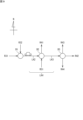
- FIG. 9 is a schematic diagram illustrating a link and its surroundings according to a modification.
- FIG. 10 is a table illustrating travel times according to a modification.
- FIG. 11 is a table illustrating travel times according to a modification.
- FIG. 12 is a schematic diagram illustrating an information generation
- the present disclosure aims to suppress an increase in operating costs when generating highly accurate travel times.
- Embodiments of the present disclosure include at least the following as gists thereof.
- the information generation system of the present disclosure includes a generation unit that generates a travel time of a link that enters from a first intersection and exits at a second intersection adjacent to the first intersection, wherein the generation unit When the absolute value of the difference between the first cycle length of the traffic signal installed at one intersection and the second cycle length of the traffic signal installed at the second intersection is less than or equal to a predetermined value, generating a plurality of types of travel times of the link for each inflow path, each outflow path from the link, or for each combination of inflow path to the link and outflow path from the link, and the first cycle length; and the second cycle length is larger than the predetermined value, one type of travel time of the link is generated regardless of the inflow path to the link and the outflow path from the link. , is an information generation system.
- the absolute value of the difference between the first cycle length and the second cycle length is less than or equal to a predetermined value (i.e., if the first cycle length and the second cycle length are substantially equal)
- travel by the inflow path and the outflow path Trends over time it is possible to further improve the accuracy of the travel time by generating a plurality of types of travel times that reflect the tendency.
- the absolute value of the difference between the first cycle length and the second cycle length is greater than the predetermined value, the inflow path and the outflow path cause little trend in the travel time. Therefore, in this case, by generating one type of travel time, it is possible to suppress an increase in processing load and an increase in storage capacity. As a result, it is possible to suppress an increase in operating costs when generating more accurate travel times.
- the information generation system of the present disclosure may further include an acquisition unit that acquires the first cycle length and the second cycle length, and the generation unit acquires the first cycle obtained by the acquisition unit. Multiple types or one type of travel time for the link may be generated based on the length and the second cycle length.
- the acquisition unit may acquire vehicle information including information on the position of the vehicle traveling on the link and the time at which the vehicle passes through the position, and the first cycle length and the and the second cycle length.
- the information generation system of the present disclosure includes an acquisition unit that acquires sub-area information that associates a plurality of intersections including the first intersection and the second intersection with sub-areas to which the plurality of intersections belong. and wherein the generation unit, based on the sub-area information acquired by the acquisition unit, if the first intersection and the second intersection belong to the same sub-area, inflow into the link
- a plurality of types of travel times for the link may be generated for each route, for each outflow route from the link, or for each combination of the inflow route to the link and the outflow route from the link.
- the generation unit Based on the sub-area information acquired by the acquisition unit, the generation unit sets a plurality of links connecting between the plurality of intersections belonging to the same sub-area as one compound link, and generates the compound link Multiple types of travel times of the composite link are generated for each inflow route to the composite link, for each outflow route from the composite link, or for each combination of the inflow route to the composite link and the outflow route from the composite link.
- the information generation system of the present disclosure includes a communication unit that receives a search request including a departure point and a destination point from a user terminal, and transmits a route from the departure point to the destination point to the user terminal; and a route search unit that searches for the route based on the travel time of the link generated by the unit.
- the generation unit generates more accurate travel times when the traffic signal cycle lengths at adjacent intersections are the same. Since the route search unit searches for a route based on such highly accurate travel times, it is possible to further improve the accuracy of search results.
- the information generation method of the present disclosure includes a generation step of generating a travel time of a link that enters from a first intersection and exits at a second intersection adjacent to the first intersection, wherein the generation step includes: When the absolute value of the difference between the first cycle length of the traffic signal installed at one intersection and the second cycle length of the traffic signal installed at the second intersection is less than or equal to a predetermined value, a first step of generating a plurality of types of travel times of the link for each inflow path, each outflow path from the link, or for each combination of inflow path to the link and outflow path from the link; When the absolute value of the difference between the first cycle length and the second cycle length is greater than the predetermined value, the travel time of the link regardless of the inflow path to the link and the outflow path from the link and a second step of generating one type.
- the absolute value of the difference between the first cycle length and the second cycle length is less than or equal to a predetermined value (i.e., if the first cycle length and the second cycle length are substantially equal)
- travel by the inflow path and the outflow path Trends over time it is possible to further improve the accuracy of the travel time by generating a plurality of types of travel times that reflect the tendency.
- the absolute value of the difference between the first cycle length and the second cycle length is greater than the predetermined value, the inflow path and the outflow path cause little trend in the travel time. Therefore, in this case, by generating one type of travel time, it is possible to suppress an increase in processing load and an increase in storage capacity. As a result, it is possible to suppress an increase in operating costs when generating more accurate travel times.
- the computer program of the present disclosure causes the computer to generate a travel time for a link entering from a first intersection and exiting at a second intersection adjacent to the first intersection, wherein the generating step comprises: , when the absolute value of the difference between the first cycle length of the traffic signal provided at the first intersection and the second cycle length of the traffic signal provided at the second intersection is equal to or less than a predetermined value, A first step of generating a plurality of travel times of the link for each inflow route to the link, for each outflow route from the link, or for each combination of the inflow route to the link and the outflow route from the link.
- the link is set regardless of whether it is an inflow path to the link or an outflow path from the link. and a second step of generating one type of travel time.
- the absolute value of the difference between the first cycle length and the second cycle length is less than or equal to a predetermined value (i.e., if the first cycle length and the second cycle length are substantially equal)
- travel by the inflow path and the outflow path Trends over time it is possible to further improve the accuracy of the travel time by generating a plurality of types of travel times that reflect the tendency.
- the absolute value of the difference between the first cycle length and the second cycle length is greater than the predetermined value, the inflow path and the outflow path cause little trend in the travel time. Therefore, in this case, by generating one type of travel time, it is possible to suppress an increase in processing load and an increase in storage capacity. As a result, it is possible to suppress an increase in operating costs when generating more accurate travel times.
- FIG. 1 is a schematic diagram illustrating an information generation system 1 according to an embodiment.
- FIG. 1 also illustrates the peripheral configuration of the information generation system 1 .
- the information generation system 1 is composed of, for example, one or a plurality of information processing apparatuses 10 .
- the information processing device 10 is installed, for example, in a private management center for providing traffic information to vehicles.
- the information processing device 10 includes a computer device 11, a communication unit 12, a map database 13, a probe information database 14, and a signal information database 15. Each of these units 11 to 15 may be realized by one information processing device 10 or may be realized by a plurality of information processing devices 10 .
- the computer device 11 includes a processing section 21 and a storage section 22 .
- the computer device 11 is, for example, a workstation.
- the processing unit 21 is, for example, a CPU (Central Processing Unit) or a GPU (Graphics Processing Unit).
- FIG. 2 is a block diagram illustrating the functional configuration of the processing unit 21 according to the embodiment.
- the processing unit 21 includes an acquisition unit 25 , a determination unit 26 , a generation unit 27 and a route search unit 28 . Functions of these units 25 to 28 will be described later.
- the storage unit 22 has a volatile memory and a nonvolatile memory, and stores various data.
- Volatile memory is, for example, RAM (Random Access Memory).
- the non-volatile memory includes, for example, flash memory, HDD (Hard Disk Drive), SSD (Solid State Drive), ROM (Read Only Memory), and the like.
- the computer device 11 further includes a reading unit (not shown).
- the reading unit reads information from the recording medium 24 .
- the recording medium 24 is a recording medium readable by the computer device 11, and is, for example, an optical disc such as a CD or DVD, or a USB flash memory.
- a computer program 23 is recorded on the recording medium 24 , and the computer program 23 read by the reading unit is stored in the non-volatile memory of the storage unit 22 .
- the communication unit 12 is a communication interface.
- the communication unit 12 communicates with the radio base station 41 and the traffic control center 42 via the network N1 (for example, the Internet).
- the wireless base station 41 communicates with a plurality of vehicles 50 to collect probe information (an example of “vehicle information” in the present disclosure) as information on the vehicles 50 and transmits the collected probe information to the communication unit 12 .
- the traffic control center 42 is a center operated by a road administrator.
- the traffic control center 42 communicates via a router 43 with a plurality of traffic signals 30 installed at intersections.
- the traffic control center 42 collects signal information of the traffic signal 30 and transmits it to the communication unit 12 .
- the traffic signal 30 includes a light unit 31 and a controller 32.
- the light unit 31 has, for example, three-color lighting portions of red, yellow, and blue, and by sequentially lighting and extinguishing these three colors, vehicles entering the intersection are permitted to proceed and prohibited from proceeding.
- the controller 32 communicates with the traffic control center 42 via the router 43.
- the controller 32 controls the lamp unit 31 based on the signal control parameters received from the traffic control center 42 .
- Signal control parameters include, for example, cycle length, split and offset.
- the controller 32 generates the lighting of each color and the extinguishing timing (step number of seconds) in the lighting section 31 according to the signal control parameters, and outputs a control signal including the lighting and extinguishing timing to the lighting section 31 .
- the cycle length is the time for the light color of the light unit 31 to make one cycle, for example, the time from the start time of the green light of the light unit 31 to the start time of the next green light.
- the split is the time allocated to each road that constitutes an intersection (or the proportion of time allocated to each road) in the cycle length, and is, for example, the time during which the light unit 31 continues to be lit in green. .
- the offset refers to the lag time (or lag ratio) between the lighting start times of the green lamps of the lamp unit 31 between adjacent intersections.
- the map database 13 is a database in which map information 16 regarding roads is recorded.
- the map information 16 includes a "directed graph" having nodes ND and links LK, "intersection data", and "link data".
- a node ND is set for each intersection. Note that the node ND may be set at a point other than the intersection (for example, a midway point on the road).
- a link LK is set to connect adjacent nodes ND, and represents the actual road shape and running direction.
- the link LK is directional in order to represent the direction of travel. In the case of a one-way road, only one-way link LK is set, and in the case of a two-way road, a pair of links LK with different directions is set.
- Road types of the link LK include, for example, general roads and toll roads.
- intersection data is data that associates the intersection IDs assigned to intersections (nodes ND) nationwide with the positions of the intersections.
- the link data is data in which link IDs of links LK assigned to roads nationwide are associated with the following information 1) to 5).
- a link cost LC is prepared for each link LK.
- the link LK required from entering the starting point of the link LK, exiting the end point of the link LK, and entering the starting point of the link LK to be connected next. includes "travel time X" of Travel time X includes link passage time and intersection passage time.
- the link transit time is the time required to travel from the start point to the end point of the link LK.
- the intersection passage time is the passage time required to travel from the end point of the link LK to the start point of the next link LK, that is, the time required to pass through the intersection connecting the link LK and the next link LK. be.
- the map database 13 stores the travel time X for each day type, such as weekdays, Saturdays, Sundays, and holidays, and for each predetermined time (for example, every 5 minutes) from the current time to one day ahead.
- the travel time X is generated, for example, based on probe information recorded in a probe information database 14, which will be described later.
- the probe information database 14 is a database in which probe information is recorded.
- the probe information is information about the travel locus of the vehicle 50, and includes, for example, information on the position of the vehicle 50 and the time at which the position is passed.
- the probe information database 14 is sequentially updated by collecting probe information from each of the plurality of vehicles 50 periodically (for example, every few seconds).
- the signal information database 15 is a database in which signal information is recorded.
- the signal information is information about a plurality of traffic signals 30, and includes signal control parameters including, for example, cycle lengths, and sub-area information.
- the subarea information is information that associates multiple intersections with the subareas to which the multiple intersections belong.
- a sub-area is a group of intersections with similar traffic patterns. Traffic signals 30 at intersections belonging to the same sub-area are systematically controlled with the same cycle length or similar cycle lengths.
- the traffic light information database 15 is sequentially updated by providing signal information from the traffic control center 42 .
- the signal information may be provided from other than the traffic control center 42 .
- the information generation system 1 collects image information of the traffic signal 30 captured by an in-vehicle camera from a plurality of vehicles 50, and acquires the green light start time and green light end time of the traffic signal 30 based on the image information.
- the cycle length and sub-area information estimated from these times may be stored in the signal information database 15 as signal information.
- FIG. 3 is a flow chart illustrating the order of an information generation method according to an embodiment.
- the flow chart of FIG. 3 shows the operation procedure of the processing unit 21 .
- the operation procedure is realized by the processing unit 21 reading the computer program 23 from the storage unit 22 and executing various calculations and processes.
- FIG. 4 is a schematic diagram illustrating the link LK1 and its surroundings according to the embodiment.
- Link LK1 corresponds to a road on which the vehicle can travel eastward, and is a link that enters at first intersection A1 and exits at second intersection A2.
- the first intersection A1 is connected to the start point of the link LK1 and to the end points of the inflow paths R11 and R12.
- the inflow roads R11 and R12 are links corresponding to roads leading into the link LK1 via the first intersection A1.
- the inflow road R11 corresponds to, for example, a road on which the vehicle can travel eastward, and is a link into which the vehicle enters the link LK1 by going straight through the first intersection A1.
- the inflow road R12 corresponds to, for example, a road on which it is possible to travel southward, and is a link that flows into the link LK1 by turning left at the first intersection A1.
- the second intersection A2 is an intersection adjacent to the first intersection A1.
- the second intersection A2 is connected to the end point of the link LK1 and to the start points of the outflow paths R21, R22 and R23.
- the exit roads R21, R22, R23 are links corresponding to roads exiting from the link LK1 via the second intersection A2.
- the exit road R21 corresponds to a road on which it is possible to travel eastward, and is a link through which the vehicle exits the link LK1 and goes straight through the second intersection A2.
- the outflow road R22 corresponds to a road on which the vehicle can travel northward, and is a link that the vehicle passes through after exiting the link LK1 and turning left at the second intersection A2.
- the exit road R23 corresponds to a road on which the vehicle can travel southward, and is a link that the vehicle passes through after exiting the link LK1 and turning right at the second intersection A2.
- a traffic signal 30 is provided at each of the first intersection A1 and the second intersection A2.
- a predetermined offset is provided between the traffic signal 30 at the first intersection A1 and the traffic signal 30 at the second intersection A2.
- the cycle length of each traffic signal 30 in A2 may be equal.
- the vehicle entering the link LK1 from the inflow path R11 and exiting from the outflow path R21 passes through the link LK1 in a relatively short period of time.
- vehicles entering the link LK1 from the inflow road R12 are likely to stop at the red light at the second intersection A2 because they enter the link LK1 when the traffic signal 30 in the east-west direction of the first intersection A1 is red. , tends to take a relatively long time to traverse the link LK1.
- a vehicle exiting from the link LK1 to the outflow road R23 has to wait for an oncoming vehicle to pass through when turning right. It tends to take time to pass. In particular, immediately after the traffic light 30 at the second intersection A2 turns green, more oncoming vehicles will pass, so the time to wait for a right turn tends to be longer.
- Vehicles entering the link LK1 from the inflow road R11 and exiting from the outflow road R23 pass through the second intersection A2 at various times, not just immediately after the traffic light 30 at the second intersection A2 turns green. Depending on the situation, the vehicle may pass through the second intersection A2 almost without waiting for a right turn.
- the vehicle entering the link LK1 from the inflow road R12 and exiting from the outflow road R23 waits for the signal at the second intersection A2, and then the traffic light 30 in the east-west direction of the second intersection A2 turns green. There is a high possibility of waiting for a right turn immediately after, and there is a tendency that it takes more time to pass through the second intersection A2.
- the information generation system 1 calculates travel times for each combination of the inflow routes R11 and R12 to the link LK1 and the outflow routes R21, R22 and R23 from the link LK1, for example. Multiple types of X1 are generated.
- the traffic signals 30 at the first intersection A1 and the second intersection A2 are controlled with different cycle lengths, the above tendency does not occur. For example, a vehicle that has gone straight from the inflow road R11 through the first intersection A1 with a green light, travels on the link LK1, and then reaches the second intersection A2. or is random. Therefore, when the traffic signals 30 at the first intersection A1 and the second intersection A2 are controlled with different cycle lengths, the inflow paths R11 and R12 to the link LK1 and the outflow paths R21 and R22 from the link LK1, Generating the travel time X1 for each combination of R23 is almost useless.
- the information generation system 1 "only" when the respective traffic signals 30 of the first intersection A1 and the second intersection A2 are controlled with the same cycle length, the inflow roads R11 and R12 to the link LK1 and the link
- the information generation system 1 By generating a plurality of types of travel times X1 for each combination of outflow routes R21, R22, and R23 from LK1, generation of more accurate travel times is realized.
- the information generation system 1 controls the inflow roads R11 and R12 to the link LK1 and from the link LK1 Only one type of travel time X1 for link LK1 is generated regardless of outflow routes R21, R22, and R23.
- the processing load on the processing unit 21 can be suppressed, and the increase in the memory capacity of the storage unit 22 required for storing the travel time X1 can be suppressed. can be suppressed.
- the information generating system 1 it is possible to suppress an increase in operating costs when generating more accurate travel times.
- the acquisition unit 25 of the processing unit 21 acquires a first cycle length T1, which is the cycle length of the traffic signal 30 provided at the first intersection A1, and the cycle length of the traffic signal 30 provided at the second intersection A2. and a second cycle length T2 (step ST11: acquisition step).
- the acquisition unit 25 acquires the first cycle length T1 and the second cycle length T2 based on the signal information stored in the signal information database 15.
- the acquisition unit 25 may estimate the first cycle length T1 and the second cycle length T2 based on probe information stored in the probe information database 14 .
- the acquisition unit 25 acquires a plurality of times from the vehicle stop time to the vehicle start time near the end point of the inflow path R11 based on the probe information. Then, the acquisition unit 25 acquires the average value of the time as the first cycle length T1.
- step ST11 ends.
- the determination unit 26 of the processing unit 21 determines whether or not the first cycle length T1 and the second cycle length T2 acquired by the acquisition unit 25 are equal (step ST12: determination step).
- the determination unit 26 determines that the first cycle length T1 and the second cycle length T2 are equal when the following formula (1) holds.
- the right side of equation (1) is the absolute value of the difference between the first cycle length T1 and the second cycle length T2.
- E1 is a margin value, for example, a value obtained by multiplying the average value of the first cycle length T1 and the second cycle length T2 by a predetermined ratio (a value of 10% or less, such as 5%).
- E1 (T1 + T2) x 1/2 x 0.05).
- T1 (T1 + T2) x 1/2 x 0.05).
- step ST12 the generation unit 27 of the processing unit 21 generates multiple types of travel times X1 for the link LK1.
- FIG. 5 is a table illustrating travel times X1 generated in step ST13.
- the generation unit 27 determines whether a plurality of vehicles that have flowed from the inflow road R11 to the link LK1 and flowed out from the link LK1 to the outflow road R21 have passed through the link LK1. Calculate the average time required. Then, the generation unit 27 temporarily stores the average time in the storage unit 22 as the travel time X1 corresponding to the combination of the inflow route R11 and the outflow route R21. In the example of FIG. 5, travel time X1 corresponding to the combination of inflow path R11 and outflow path R21 is 15 seconds.
- the generating unit 27 Based on the probe information, the generating unit 27 generates a travel time X1 (for example, 20 seconds) corresponding to the combination of the inflow path R11 and the outflow path R22, and a travel time X1 corresponding to the combination of the inflow path R11 and the outflow path R23.
- a time X1 (for example, 30 seconds), a travel time X1 (for example, 40 seconds) corresponding to the combination of the inflow route R12 and the outflow route R21, and a travel time X1 (for example, , 45 seconds) and a travel time X1 (eg, 55 seconds) corresponding to the combination of the inflow path R12 and the outflow path R23.
- the generation unit 27 temporarily stores these five types of travel times X1 in the storage unit 22 .
- the storage unit 22 temporarily stores the six types of travel times X1 in the form of a table in association with combinations of the inflow paths R11, R12 and the outflow paths R21, R22, R23, for example, as shown in FIG. do. After generating the travel times X1 corresponding to all the combinations, the generation unit 27 stores the six types of travel times X1 stored in the storage unit 22 in the map database 13, thereby updating the map database 13. .
- the travel time X1 has a tendency due to the inflow paths R11 and R12 and the outflow paths R21, R22, and R23.
- the accuracy of the travel times X1 can be increased. Further, in this embodiment, it is possible to determine whether to generate a plurality of types of travel times X1 for the link LK1 or to generate one type based on the first cycle length T1 and the second cycle length T2.
- the determination unit 27 determines that the second cycle length T2 is different.
- the generation unit 27 of the processing unit 21 generates one type of travel time X1 for the link LK1.
- step ST14 second step of the generating step. More specifically, the generation unit 27 sets the travel time X1 to 1 for the link LK1 regardless of the two inflow routes R11 and R12 to the link LK1 and the three outflow routes R21, R22, and R23 from the link LK1. Generates types only.
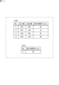
- FIG. 6 is a table illustrating travel times X1 generated in step ST14.
- the generation unit 27 calculates the average time required for a plurality of vehicles to pass through the link LK1 based on the probe information stored in the probe information database 14, for example. At this time, the generation unit 27 does not consider the inflow paths R11 and R12 and the outflow paths R21, R22, and R23 through which the multiple vehicles pass, for example, for the multiple vehicles that have passed through the link LK1 within a predetermined period, Calculate the average time required to pass LK1. Then, the generation unit 27 temporarily stores the average time in the storage unit 22 as the travel time X1 of the link LK1. In the example of FIG. 6, travel time X1 is 35 seconds.
- the generation unit 27 After generating the travel time X1, the generation unit 27 updates the map database 13 by storing one type of travel time X1 stored in the storage unit 22 in the map database 13. As a result, when the first cycle length T1 and the second cycle length T2 are different, there is almost no tendency in the travel time X1 due to the inflow paths R11, R12 and the outflow paths R21, R22, R23.
- By generating one type of travel time X1 an increase in the processing load on the processing unit 21 can be suppressed, and an increase in the storage capacity of the storage unit 22 and the map database 13 can be suppressed. As a result, an increase in operating costs can be suppressed when generating the travel time X1.
- step ST15 route search step
- FIG. 7 is a subroutine illustrating the details of the route search step.
- the information generation system 1 receives a search request including a starting point and a destination point from the user terminal (step ST16: receiving step).
- the user terminal may be, for example, a navigation device (not shown) mounted on the vehicle 50 or a communication terminal such as a smart phone owned by a passenger of the vehicle 50 .
- a search request may include a departure time or an arrival time.
- the search request transmitted from the user terminal is received by the communication unit 12 via the wireless base station 41 and network N1.
- the communication unit 12 outputs the received search request to the computer device 11 .
- the route search unit 28 of the processing unit 21 executes route search processing based on the search request (step ST17). For example, the route search unit 28 selects the node ND closest to the starting point as the start node, the node ND closest to the destination point as the end node, and selects the link data from the start node to the end node from the link data included in the map information 16. Get network data, including Next, the route search unit 28 searches for a route that minimizes the accumulated link cost LC from the starting point to the destination point among the routes included in the acquired network data.
- the route search unit 28 uses a search algorithm based on the Dijkstra method or the potential method to search for a route with the smallest accumulated link cost LC.
- the link cost LC is calculated, for example, by Equation (2) below.
- LC is the "link cost”
- X is the “travel time”
- LD is the "link distance”.
- C1 and C2 are coefficients that can be set for each user, for example. That is, the link cost LC is calculated based on the travel time X of the link LK (for example, the travel time X1 of the link LK1).
- a time-prioritized route is a route (a route with a short required time) that can reach the destination faster, and a route with a shorter travel time X.
- FIG. When a time-prioritized route is selected in the search request, the coefficient C1 takes a larger value and the coefficient C2 takes a smaller value in order to increase the weight of the travel time X in the link cost LC.
- a distance-prioritized route is a route that can reach a destination point in a shorter distance, and a route with a smaller link distance LD.
- the coefficient C2 takes a larger value and the coefficient C1 takes a smaller value in order to increase the weight of the link distance LD in the link cost LC.
- a balanced route is a route that balances the required time and distance.
- the coefficient C1 has a smaller value than the time-prioritized route
- the coefficient C2 has a smaller value than the distance-prioritized route.
- the route search unit 28 stores the route with the smallest accumulated link cost LC in the storage unit 22 as the "optimum route". Only one type of optimal route may be calculated, or multiple types of optimal routes including the above-described "time priority route”, “distance priority route”, and “balanced route” may be calculated.
- the information generation system 1 transmits the optimum route acquired by the route search unit 28 to the user terminal (step ST18: transmission step). For example, information including the optimum route is output from the computer device 11 to the communication unit 12 .
- the communication unit 12 transmits information including the optimum route to the user terminal.
- the information transmitted from the communication unit 12 is received by the user terminal via the radio base station 41 and the network N1.
- the user terminal displays the information to the user.
- the route searching unit 28 searches for a route based on the travel time X of the link LK generated by the generating unit 27.
- the generation unit 27 generates a more accurate travel time X when the cycle lengths of the traffic signals 30 at adjacent intersections are equal. Since the route search unit 28 searches for a route based on such a highly accurate travel time X, it is possible to further improve the accuracy of the search result.
- FIG. 8 is a flowchart illustrating the order of the information generation method according to the modification.
- the flowchart of FIG. 8 shows the operation procedure of the processing unit 21 .
- the operation procedure is realized by the processing unit 21 reading the computer program 23 from the storage unit 22 and executing various calculations and processes.
- the acquisition unit 25 of the above embodiment acquires the first cycle length T1 and the second cycle length T2 based on signal information or probe information.
- the acquisition unit 25 of this modification does not acquire the cycle length of the traffic signal 30, but acquires sub-area information regarding the sub-area to which the intersection belongs.
- the traffic signal 30 has the same cycle length. Therefore, based on whether the sub-areas to which the plurality of intersections belong are the same, it is possible to indirectly grasp whether the cycle lengths of the traffic signals 30 provided at the plurality of intersections are the same.
- the determination unit 26 of this modification determines whether to generate a plurality of types of link travel times X or to generate only one type based on the sub-area information.
- FIG. 9 is a schematic diagram illustrating links LK2 and LK3 and their surroundings according to the modification. Both links LK2 and LK3 correspond to roads on which the vehicle can travel eastward.
- the link LK2 is a link that enters from the first intersection B1 and exits to the second intersection B2.
- the link LK3 is a link that enters from the second intersection B2 and exits to the third intersection B3.
- the first intersection B1 is connected to the starting point of the link LK2 and to the end points of the inflow paths R31 and R32.
- the inflow roads R31 and R32 are links corresponding to roads leading into the link LK2 via the first intersection B1.
- the inflow road R31 corresponds to, for example, a road on which the vehicle can travel eastward, and is a link into which the vehicle enters the link LK2 by going straight through the first intersection B1.
- the inflow road R32 corresponds to, for example, a road on which it is possible to travel southward, and is a link that flows into the link LK2 by turning left at the first intersection B1.
- the second intersection B2 is an intersection adjacent to the first intersection B1.
- the second intersection B2 is connected to the end point of link LK2 and the start point of link LK3.
- the second intersection B2 is further connected to the end point of the inflow path R51 and the start point of the outflow path R41.
- the inflow road R51 is a link corresponding to a northward travelable road that flows into the link LK3 or the outflow road R41 via the second intersection B2.
- the outflow road R41 is a link corresponding to a northward travelable road exiting from the link LK2 or the inflow road R51 via the second intersection B2.
- the third intersection B3 is an intersection adjacent to the second intersection B2.
- the third intersection B3 is connected to the end point of the link LK3 and to the start points of the outflow paths R42, R43, R44.
- Outflow roads R42, R43, and R44 are links corresponding to roads exiting link LK3 via third intersection B3.
- the exit road R42 corresponds to a road on which the vehicle can travel eastward, and is a link that the vehicle passes through after exiting the link LK3 and going straight through the third intersection B3.
- the outflow road R43 corresponds to a road on which the vehicle can travel northward, and is a link that the vehicle passes through after exiting the link LK3 and turning left at the third intersection B3.
- the outflow road R44 corresponds to a road on which the vehicle can travel southward, and is a link through which the vehicle exits the link LK3 and turns right at the third intersection B3.
- a traffic signal 30 is provided at each of the first intersection B1, the second intersection B2 and the third intersection B3.
- the first intersection B1, the second intersection B2, and the third intersection B3 are provided with a predetermined offset between the traffic signals 30.
- the cycle lengths of the traffic signals 30 at B1, the second intersection B2 and the third intersection B3 may be equal. This makes it easier for a vehicle that has gone straight through the first intersection B1 from the inflow road R31 with green lights to pass through the second intersection B2 and the third intersection B3 with green lights after traveling on the link LK2. And traffic congestion on the link LK3 can be suppressed.
- a group of intersections controlled by a common cycle length is referred to as a "sub-area".
- the traffic control center 42 when systematically controlling the traffic signals 30 provided at a plurality of mutually adjacent intersections, a group of intersections controlled by a common cycle length is referred to as a "sub-area".
- the traffic control center 42 generates sub-area information that associates a plurality of intersections with the sub-areas to which the plurality of intersections belong.
- Subarea information is stored in the signal information database 15 after being provided to the information generation system 1 from the traffic control center 42 .
- Signal control parameters are determined for each sub-area by the traffic control center 42, for example.
- the generation unit 27 of this modified example treats a plurality of links LK2 and LK3 connecting a plurality of intersections B1, B2, and B3 belonging to the same sub-area as one composite link LK4, and generates a link to the composite link LK4.
- Multiple types of travel times X2 of the composite link LK4 are generated for each combination of the inflow routes R31, R32 and the outflow routes R42, R43, R44 from the composite link LK4. This makes it possible to generate a more accurate travel time by taking into account the effect of signal waiting time being omitted by systematic control of traffic signals 30 at intersections belonging to the same sub-area.
- the information generation system 1 generates the travel time X2 of the composite link LK4 shown in FIG. 9 and the travel times X3 and X4 of the links LK2 and LK3 (or travel A specific method for generating times X5 and X6) will be described.
- the acquisition unit 25 acquires sub-area information in which a plurality of intersections including the first intersection B1, the second intersection B2 and the third intersection B3 are associated with the sub-areas to which the plurality of intersections belong (step ST21: acquisition step). For example, the acquisition unit 25 acquires subarea information stored in the signal information database 15 .
- the determination unit 26 of the processing unit 21 determines whether or not the first intersection B1 and the second intersection B2 belong to the same sub-area based on the sub-area information acquired by the acquisition unit 25 (step ST22). : judgment step).
- the determination unit 26 determines that the first intersection B1 and the second intersection B2 belong to the same sub-area (YES route in step ST22)
- the determination unit 26 based on the sub-area information acquired by the acquisition unit 25, It is determined whether a plurality of links are included in the sub-area to which the first intersection B1 and the second intersection B2 belong (step ST23).
- the determination unit 26 determines whether another intersection adjacent to the first intersection B1 or the second intersection B2 belongs to the same sub-area as the first intersection B1 and the second intersection B2. Then, when determining that the other intersection belongs to the same sub-area as the first intersection B1 and the second intersection B2, the determination unit 26 determines that a plurality of intersections exist within the sub-area to which the first intersection B1 and the second intersection B2 belong. Determine that the link is included. In the example of FIG. 9, the third intersection B3 belongs to the same sub-area as the first intersection B1 and the second intersection B2, so the determination unit 26 determines that the sub-area includes multiple links LK2 and LK3.
- step ST24 the generation unit 27 determines the travel time X3 when exiting from the middle of the composite link LK4 (i.e. the travel time X3 of the link LK2) and the travel time X4 when entering from the middle of the composite link LK4 (i.e. and travel time X4) of link LK3.
- FIG. 10 is a table illustrating travel times X2, X3, and X4 generated in step ST24.
- the generation unit 27 Based on the probe information stored in the probe information database 14, for example, the generation unit 27 generates a plurality of vehicles that have entered the combined link LK4 from the inflow road R31 and exited from the combined link LK4 to the outflow road R42. Calculate the average time required to pass the Then, the generation unit 27 temporarily stores the average time in the storage unit 22 as the travel time X2 corresponding to the combination of the inflow route R31 and the outflow route R42. In the example of FIG. 10, travel time X2 corresponding to the combination of inflow path R31 and outflow path R42 is 40 seconds.
- the generating unit 27 determines a travel time X2 (for example, 45 seconds) corresponding to the combination of the inflow path R31 and the outflow path R43, and a travel time X2 corresponding to the combination of the inflow path R31 and the outflow path R44.
- a travel time X2 for example, 45 seconds
- a time X2 (for example, 60 seconds), a travel time X2 (for example, 60 seconds) corresponding to the combination of the inflow path R32 and the outflow path R42, and a travel time X2 (for example, 60 seconds) corresponding to the combination of the inflow path R32 and the outflow path R43 , 65 seconds) and a travel time X2 (eg, 80 seconds) corresponding to the combination of the inflow path R32 and the outflow path R44.
- the generation unit 27 temporarily stores these five types of travel times X2 in the storage unit 22 .
- the storage unit 22 temporarily stores the six types of travel times X2 in the form of a table in association with combinations of the inflow paths R31, R32 and the outflow paths R42, R43, R44, for example, as shown in FIG. do.
- the generator 27 calculates the average time required for a plurality of vehicles that have entered the link LK2 from the inflow route R31 and exited from the link LK2 to the outflow route R41 to pass through the link LK2. Then, the generation unit 27 temporarily stores the average time in the storage unit 22 as the travel time X3 corresponding to the combination of the inflow route R31 and the outflow route R41. In the example of FIG. 10, travel time X3 corresponding to the combination of inflow path R31 and outflow path R41 is 20 seconds. Similarly, the generation unit 27 generates a travel time X3 (for example, 45 seconds) corresponding to the combination of the inflow route R32 and the outflow route R41 based on the probe information, and temporarily stores it in the storage unit 22.
- travel time X3 for example, 45 seconds
- the generation unit 27 Based on the probe information, the generation unit 27 also calculates the average time required for a plurality of vehicles that have entered the link LK3 from the inflow route R51 and exited from the link LK3 to the outflow route R42 to pass through the link LK3. Then, the generation unit 27 temporarily stores the average time in the storage unit 22 as the travel time X4 corresponding to the combination of the inflow route R51 and the outflow route R42. In the example of FIG. 10, travel time X4 corresponding to the combination of inflow path R51 and outflow path R42 is 40 seconds.
- the generating unit 27 Based on the probe information, the generating unit 27 generates a travel time X4 (for example, 45 seconds) corresponding to the combination of the inflow path R51 and the outflow path R43, and a travel time X4 corresponding to the combination of the inflow path R51 and the outflow path R44.
- a time X4 (for example, 55 seconds) is generated and temporarily stored in the storage unit 22 .
- the generation unit 27 After generating the travel times X2, X3, and X4 corresponding to all combinations, the generation unit 27 stores the plurality of types of travel times X2, X3, and X4 stored in the storage unit 22 in the map database 13. Thus, the map database 13 is updated.
- the generation unit 27 when the determination unit 26 determines that the first intersection B1 and the second intersection B2 belong to different sub-areas (NO route in step ST22), the generation unit 27 generates one type of travel time X3 for the link LK2. Generate (step ST26). More specifically, the generation unit 27 generates only one type of travel time X3 for the link LK2 regardless of the two inflow paths R31 and R32 to the link LK2 and the outflow path R41 and link LK3 that flow out from the link LK2. do. As a result, as in the above-described embodiment, it is possible to suppress an increase in operating costs when generating the travel time X3.
- the generating unit 27 when the determination unit 26 determines that the sub-area to which the first intersection B1 and the second intersection B2 belong does not include a plurality of links (that is, the determination unit 26 determines that the third intersection B3 is the first intersection B1 and the second intersection B2 belong to a different sub-area: NO route in step ST23), the generating unit 27 generates a plurality of links LK2 and LK3 without forming one composite link LK4. Travel times X5 and X6 are generated for LK2 and LK3, respectively (step ST25).
- FIG. 11 is a table exemplifying travel times X5 and X6 generated in step ST25.
- step ST22 is followed by the YES route
- the first intersection B1 and the second intersection B2 belong to the same sub-area. Therefore, since the cycle lengths of the traffic signals 30 provided at the first intersection B1 and the second intersection B2 are the same, the travel time X5 of the link LK2 is calculated using the inflow roads R31, R32 and the link A plurality of types are generated for each combination of LK3 (functioning as one of the outflow paths here) and outflow path R41.
- the third intersection B3 belongs to a sub-area different from the first intersection B1 and the second intersection B2, the cycle length of the traffic signal 30 provided at the third intersection B3 is the same as that provided at the second intersection B2. different from the cycle length of the traffic signal 30 that is present. For this reason, the travel time X6 of the link LK3 is set to be Only one type is generated.
- the generating unit 27 determines that a plurality of vehicles that have flowed from the inflow road R31 to the link LK2 and flowed out from the link LK2 to the outflow road R41 have passed through the link LK2. Calculate the average time required for Then, the generation unit 27 temporarily stores the average time in the storage unit 22 as the travel time X5 corresponding to the combination of the inflow path R31 and the outflow path R41. In the example of FIG. 11, travel time X5 corresponding to the combination of inflow path R31 and outflow path R41 is 20 seconds.
- the generation unit 27 Based on the probe information, the generation unit 27 generates a travel time X5 (for example, 15 seconds) corresponding to the combination of the inflow route R31 and the link LK3 (corresponding to the outflow route), A travel time X5 (for example, 45 seconds) corresponding to the combination and a travel time X5 (for example, 40 seconds) corresponding to the combination of the inflow path R32 and the link LK3 are generated. Then, the generation unit 27 temporarily stores these three types of travel times X5 in the storage unit 22 .
- a travel time X5 for example, 15 seconds
- a travel time X5 for example, 45 seconds
- a travel time X5 for example, 40 seconds
- the generation unit 27 also calculates the average time required for the plurality of vehicles to pass through the link LK3 based on the probe information. At this time, the generating unit 27 does not consider the link LK2 (corresponding to the inflow path), the inflow path R51, and the outflow paths R42, R43, and R44 through which the plurality of vehicles pass, for example, the link LK3 within a predetermined period. The average time required to pass the link LK3 is calculated for the plurality of vehicles. Then, the generation unit 27 temporarily stores the average time in the storage unit 22 as the travel time X6 of the link LK3. In the example of FIG. 11, travel time X6 is 45 seconds.
- the generation unit 27 After generating the travel times X5 and X6, the generation unit 27 updates the map database 13 by storing the travel times X5 and X6 stored in the storage unit 22 in the map database 13 . As described above, by generating a plurality of types of travel times X5 with higher accuracy for the link LK2 and generating a single type of travel time X6 for the link LK3, an increase in operating costs can be suppressed.
- the information generating system 1 searches for a route in response to the search request (step ST15: route search step), as in the above embodiment.
- the route search unit searches for a route based on the travel times X2, X3, X4 or based on the travel times X5, X6. Thereby, the accuracy of the search result can be further improved.
- step ST13 the generation unit 27 of the embodiment generates six types of travel times X1 for each combination of the inflow routes R11 and R12 to the link LK1 and the outflow routes R21, R22 and R23 from the link LK1.
- the generator 26 may generate two types of travel times X1 for each of the inflow routes R11 and R12 to the link LK1 regardless of the outflow routes R21, R22 and R23 from the link LK1.
- the generation unit 26 may generate three types of travel times X1 for each of the outflow routes R21, R22, and R23 from the link LK1 regardless of the inflow routes R11 and R12 to the link LK1. Even in the case of such a configuration, the travel time can be generated with higher accuracy than when only one type of travel time is generated regardless of the inflow paths R11, R12 and the outflow paths R21, R22, R23. can be done.
- the generator 26 performs Alternatively, a plurality of types of travel times X1 for the link LK1 may be generated for each combination of the inflow routes R11, R12 to the link LK1 and the outflow routes R21, R22, R23 from the link LK1.
- step ST24 the generator 26 of the modified example generates six travel times X2 for each combination of the inflow routes R31 and R32 to the composite link LK4 and the outflow routes R42, R43 and R44 from the composite link LK4.
- the generator 26 may generate two types of travel times X2 for each of the inflow routes R31 and R32 to the composite link LK4 regardless of the outflow routes R42, R43 and R44 from the composite link LK4. .
- the generation unit 26 may generate three types of travel times X2 for each of the outflow routes R42, R43, and R44 from the composite link LK4 regardless of the inflow routes R31 and R32 to the composite link LK4. .
- the travel time can be generated with higher accuracy than when only one type of travel time is generated regardless of the inflow paths R31, R32 and the outflow paths R42, R43, R44. can be done. Further, by generating the travel time X2 with the links LK2 and LK3 as one composite link LK4, it is possible to take into account the omission of the signal waiting time, etc., so that a more accurate travel time can be generated.
- the generation unit 26 treats the plurality of links LK2 and LK3 as one composite link LK4, and connects the plurality of links LK2 and LK3 to the composite link LK4.
- Each inflow path R31, R32, each outflow path R42, R43, R44 from the composite link LK4, or a combination of the inflow path R31, R32 to the composite link LK4 and the outflow path R42, R43, R44 from the composite link LK4 A plurality of types of travel times X2 of the composite link LK4 may be generated for each.
- the acquisition unit 25 acquires the subarea information itself. However, after acquiring the cycle lengths of the traffic signals 30 in the same manner as in the embodiment shown in FIG. The subarea to which each belongs may be estimated.
- the acquisition unit 25 acquires the cycle lengths of the traffic signals 30 installed at the first intersection B1, the second intersection B2, and the third intersection B3. Then, if these cycle lengths are equal, the acquisition unit 25 estimates that the first intersection B1, the second intersection B2, and the third intersection B3 belong to the same sub-area, and outputs information to that effect to the determination unit 26. . Even in the case of such a configuration, the processing section 21 can execute steps ST22 to ST26 in the same manner as in the above modified example.
- FIG. 12 is a schematic diagram illustrating an information generation system 1a according to a modification.
- the radio base station 41, traffic control center 42 and router 43 are omitted.
- the information generating system 1a of FIG. 12 has a plurality of edge servers 70, and each process executed by the processing unit 21 of the above embodiment is shared between the plurality of edge servers 70 and the processing unit 21 in this modification. .
- the edge server 70 is installed, for example, in each predetermined area of responsibility, and collects probe information and signal information in the area of responsibility.
- the edge server 70 communicates with the communication unit 12 of the information processing device 10 via the network N1.
- the edge server 70 collects probe information from the vehicle 50 via the radio base station 41 and transmits the collected probe information to the information processing device 10 .
- the edge server 70 collects signal information of the traffic signal 30 from the traffic control center 42 and transmits the collected signal information to the information processing device 10 .
- the edge server 70 executes, for example, each process from step ST11 to step ST12 in FIG. 3, and transmits the determination result to the information processing device 10 via the network N1.
- the information processing apparatus 10 generates a travel time X based on the determination result (step ST13 or step ST14), and performs a route search based on the travel time X (step ST15). That is, among the functions shown in FIG. 2 , the edge server 70 may implement the acquisition unit 25 and the determination unit 26 , and the processing unit 21 may implement the generation unit 27 and the route search unit 28 . By sharing each process between the plurality of edge servers 70 and the processing unit 21, the processing load on the processing unit 21 can be reduced.
- probe information is given as an example of vehicle information.
- vehicle information is not limited to probe information, for example, may be information based on image information obtained from various cameras that capture road conditions, vehicle detectors installed on roads may be information based on the sensing result of Various cameras include, for example, in-vehicle cameras, cameras installed at intersections and along roads (eg, security cameras).
Landscapes
- Engineering & Computer Science (AREA)
- Radar, Positioning & Navigation (AREA)
- Remote Sensing (AREA)
- Physics & Mathematics (AREA)
- General Physics & Mathematics (AREA)
- Automation & Control Theory (AREA)
- Traffic Control Systems (AREA)
Priority Applications (1)
| Application Number | Priority Date | Filing Date | Title |
|---|---|---|---|
| JP2023563522A JPWO2023095408A1 (https=) | 2021-11-29 | 2022-08-30 |
Applications Claiming Priority (2)
| Application Number | Priority Date | Filing Date | Title |
|---|---|---|---|
| JP2021192837 | 2021-11-29 | ||
| JP2021-192837 | 2021-11-29 |
Publications (1)
| Publication Number | Publication Date |
|---|---|
| WO2023095408A1 true WO2023095408A1 (ja) | 2023-06-01 |
Family
ID=86539117
Family Applications (1)
| Application Number | Title | Priority Date | Filing Date |
|---|---|---|---|
| PCT/JP2022/032541 Ceased WO2023095408A1 (ja) | 2021-11-29 | 2022-08-30 | 情報生成システム、情報生成方法及びコンピュータプログラム |
Country Status (2)
| Country | Link |
|---|---|
| JP (1) | JPWO2023095408A1 (https=) |
| WO (1) | WO2023095408A1 (https=) |
Citations (7)
| Publication number | Priority date | Publication date | Assignee | Title |
|---|---|---|---|---|
| JP2000285362A (ja) * | 1999-03-31 | 2000-10-13 | Toyota Central Res & Dev Lab Inc | ナビゲーション装置 |
| JP2001165684A (ja) * | 1999-09-29 | 2001-06-22 | Matsushita Electric Ind Co Ltd | 経路選出方法およびシステム |
| JP2012003344A (ja) * | 2010-06-14 | 2012-01-05 | Nomura Research Institute Ltd | 旅行時間提供装置、旅行時間提供方法及び旅行時間提供プログラム |
| JP2014035273A (ja) * | 2012-08-09 | 2014-02-24 | Aisin Aw Co Ltd | コスト算出装置、コスト算出プログラム、及びナビゲーション装置 |
| JP2018165665A (ja) * | 2017-03-28 | 2018-10-25 | アイシン・エィ・ダブリュ株式会社 | 経路探索装置及びコンピュータプログラム |
| JP2021124336A (ja) * | 2020-02-04 | 2021-08-30 | 住友電気工業株式会社 | 経路探索装置、経路探索方法及びコンピュータプログラム |
| CN113327419A (zh) * | 2021-05-31 | 2021-08-31 | 北京百度网讯科技有限公司 | 绿波速度确定方法、装置、电子设备和存储介质 |
-
2022
- 2022-08-30 JP JP2023563522A patent/JPWO2023095408A1/ja active Pending
- 2022-08-30 WO PCT/JP2022/032541 patent/WO2023095408A1/ja not_active Ceased
Patent Citations (7)
| Publication number | Priority date | Publication date | Assignee | Title |
|---|---|---|---|---|
| JP2000285362A (ja) * | 1999-03-31 | 2000-10-13 | Toyota Central Res & Dev Lab Inc | ナビゲーション装置 |
| JP2001165684A (ja) * | 1999-09-29 | 2001-06-22 | Matsushita Electric Ind Co Ltd | 経路選出方法およびシステム |
| JP2012003344A (ja) * | 2010-06-14 | 2012-01-05 | Nomura Research Institute Ltd | 旅行時間提供装置、旅行時間提供方法及び旅行時間提供プログラム |
| JP2014035273A (ja) * | 2012-08-09 | 2014-02-24 | Aisin Aw Co Ltd | コスト算出装置、コスト算出プログラム、及びナビゲーション装置 |
| JP2018165665A (ja) * | 2017-03-28 | 2018-10-25 | アイシン・エィ・ダブリュ株式会社 | 経路探索装置及びコンピュータプログラム |
| JP2021124336A (ja) * | 2020-02-04 | 2021-08-30 | 住友電気工業株式会社 | 経路探索装置、経路探索方法及びコンピュータプログラム |
| CN113327419A (zh) * | 2021-05-31 | 2021-08-31 | 北京百度网讯科技有限公司 | 绿波速度确定方法、装置、电子设备和存储介质 |
Also Published As
| Publication number | Publication date |
|---|---|
| JPWO2023095408A1 (https=) | 2023-06-01 |
Similar Documents
| Publication | Publication Date | Title |
|---|---|---|
| US9830813B2 (en) | Smart and scalable urban signal networks: methods and systems for adaptive traffic signal control | |
| US9159229B2 (en) | Smart and scalable urban signal networks: methods and systems for adaptive traffic signal control | |
| CN106092111B (zh) | 一种车辆路径动态规划方法、服务器及导航系统 | |
| AU2011380820B2 (en) | Autonomous travel system | |
| Wang et al. | A multi-agent based vehicles re-routing system for unexpected traffic congestion avoidance | |
| CN108629455B (zh) | 一种基于车辆自组织网的实时路径规划方法 | |
| US20080270014A1 (en) | Apparatus, method, and program for generating road information | |
| JP6777151B2 (ja) | ルート探索方法及びルート探索装置 | |
| CN113418530A (zh) | 车辆行驶路径生成方法及系统 | |
| CN105283912A (zh) | 停车场引导装置、停车场引导方法、停车场引导程序 | |
| WO2011111145A1 (ja) | 経路探索装置 | |
| JP2007122584A (ja) | 交通信号制御システム、および交通信号制御システムの制御方法 | |
| JP5768526B2 (ja) | 渋滞予測装置および渋滞予測データ | |
| CN112071095A (zh) | 一种基于v2x技术的应急车辆通过交叉口的信号配时方法 | |
| JP3551241B2 (ja) | 道路地図における経路探索条件の決定方法 | |
| WO2023095408A1 (ja) | 情報生成システム、情報生成方法及びコンピュータプログラム | |
| CN109887295A (zh) | 一种基于路灯区块链技术的交通路况监测方法 | |
| Zhu et al. | Traffic big data based path planning strategy in public vehicle systems | |
| Elbery et al. | Vehicular crowd management: An iot-based departure control and navigation system | |
| Guanetti et al. | Eco-routing of connected plug-in hybrid electric vehicles | |
| CN107147582B (zh) | 一种车辆自组织网络混合型路由生成算法 | |
| WO2024048008A1 (ja) | 車載装置、判定方法、情報提供システム、及びコンピュータプログラム | |
| WO2009119039A1 (en) | Stop history data accumulation system, accumulation method, and accumulation program | |
| JP2013160751A (ja) | 経路探索装置、サーバ装置、経路探索システム、制御方法、プログラム、及び記憶媒体 | |
| CN115223389B (zh) | 一种基于动态路段代价的停车引导路径规划方法 |
Legal Events
| Date | Code | Title | Description |
|---|---|---|---|
| 121 | Ep: the epo has been informed by wipo that ep was designated in this application |
Ref document number: 22898193 Country of ref document: EP Kind code of ref document: A1 |
|
| WWE | Wipo information: entry into national phase |
Ref document number: 2023563522 Country of ref document: JP |
|
| NENP | Non-entry into the national phase |
Ref country code: DE |
|
| 122 | Ep: pct application non-entry in european phase |
Ref document number: 22898193 Country of ref document: EP Kind code of ref document: A1 |