WO2023095325A1 - 冷凍サイクル装置 - Google Patents
冷凍サイクル装置 Download PDFInfo
- Publication number
- WO2023095325A1 WO2023095325A1 PCT/JP2021/043598 JP2021043598W WO2023095325A1 WO 2023095325 A1 WO2023095325 A1 WO 2023095325A1 JP 2021043598 W JP2021043598 W JP 2021043598W WO 2023095325 A1 WO2023095325 A1 WO 2023095325A1
- Authority
- WO
- WIPO (PCT)
- Prior art keywords
- refrigerant
- working fluid
- heat exchanger
- flow path
- refrigeration cycle
- Prior art date
- Legal status (The legal status is an assumption and is not a legal conclusion. Google has not performed a legal analysis and makes no representation as to the accuracy of the status listed.)
- Ceased
Links
Images







Classifications
-
- F—MECHANICAL ENGINEERING; LIGHTING; HEATING; WEAPONS; BLASTING
- F25—REFRIGERATION OR COOLING; COMBINED HEATING AND REFRIGERATION SYSTEMS; HEAT PUMP SYSTEMS; MANUFACTURE OR STORAGE OF ICE; LIQUEFACTION SOLIDIFICATION OF GASES
- F25B—REFRIGERATION MACHINES, PLANTS OR SYSTEMS; COMBINED HEATING AND REFRIGERATION SYSTEMS; HEAT PUMP SYSTEMS
- F25B1/00—Compression machines, plants or systems with non-reversible cycle
-
- F—MECHANICAL ENGINEERING; LIGHTING; HEATING; WEAPONS; BLASTING
- F25—REFRIGERATION OR COOLING; COMBINED HEATING AND REFRIGERATION SYSTEMS; HEAT PUMP SYSTEMS; MANUFACTURE OR STORAGE OF ICE; LIQUEFACTION SOLIDIFICATION OF GASES
- F25B—REFRIGERATION MACHINES, PLANTS OR SYSTEMS; COMBINED HEATING AND REFRIGERATION SYSTEMS; HEAT PUMP SYSTEMS
- F25B13/00—Compression machines, plants or systems, with reversible cycle
-
- F—MECHANICAL ENGINEERING; LIGHTING; HEATING; WEAPONS; BLASTING
- F25—REFRIGERATION OR COOLING; COMBINED HEATING AND REFRIGERATION SYSTEMS; HEAT PUMP SYSTEMS; MANUFACTURE OR STORAGE OF ICE; LIQUEFACTION SOLIDIFICATION OF GASES
- F25B—REFRIGERATION MACHINES, PLANTS OR SYSTEMS; COMBINED HEATING AND REFRIGERATION SYSTEMS; HEAT PUMP SYSTEMS
- F25B49/00—Arrangement or mounting of control or safety devices
- F25B49/02—Arrangement or mounting of control or safety devices for compression type machines, plants or systems
Definitions
- the present disclosure relates to a refrigeration cycle device, and more particularly to a refrigeration cycle device provided with an optical sensor.
- the refrigerant discharged from the compressor is condensed in the condenser to become liquid refrigerant.
- the liquid refrigerant is decompressed by the expansion device, and becomes a gas-liquid two-phase state in which the gas refrigerant and the liquid refrigerant are mixed.
- the gas-liquid two-phase refrigerant is turned into a low-pressure gas refrigerant by evaporating the liquid refrigerant in the gas-liquid two-phase refrigerant in the evaporator.
- the low-pressure gas refrigerant that has flowed out of the evaporator is sucked into the compressor, compressed into high-temperature and high-pressure gas refrigerant, and discharged from the compressor again. This cycle is repeated in the refrigeration cycle device.
- the refrigerant discharged from the compressor may contain excessive refrigeration oil. It is also known that when a non-azeotropic mixed refrigerant is used as a working fluid in a refrigeration cycle device, the circulating composition ratio of the refrigerant changes depending on operating conditions such as cooling or heating. When the circulation composition ratio of the refrigerant changes, the saturation temperature of the refrigerant cannot be accurately detected, and this may cause excessive liquid refrigerant to flow into the compressor. In this case, the refrigerating machine oil in the compressor is diluted and seizure occurs, which causes the compressor to malfunction.
- Spectroscopic measuring means using an optical sensor is known as means for measuring the component concentration of the working fluid (see, for example, Patent Document 1).
- an optical sensor is provided in the refrigerant pipe from the condenser to the receiver.
- the degree of subcooling at the outlet of the condenser decreases, and gas refrigerant mixes with the refrigerant flowing through the refrigerant pipe from the condenser to the receiver.
- a gas-liquid interface is formed in the refrigerant pipe, and the component concentration of the working fluid may not be accurately measured due to light scattering or a difference in flow velocity between the liquid phase and the gas phase.
- the present disclosure is intended to solve the above problems, and aims to improve the measurement accuracy of the component concentration of the working fluid in the refrigeration cycle device.
- a refrigeration cycle apparatus includes a compressor that compresses and discharges a working fluid, a condenser that condenses the working fluid discharged from the compressor, and a condensed fluid flow path through which the working fluid discharged from the condenser flows. and a low-pressure flow path through which a working fluid having a pressure lower than that of the working fluid flowing through the condensed fluid flow path flows, wherein heat is exchanged between the working fluid flowing through the condensed fluid flow path and the working fluid flowing through the low-pressure flow path.
- a first expansion device that decompresses the working fluid that has flowed out of the condensed fluid flow path of the heat exchanger between refrigerants; an evaporator that evaporates the working fluid decompressed by the first expansion device; and the heat exchanger between refrigerants.
- an optical sensor provided in a pipe connecting the outlet of the condensed fluid flow path and the first throttle device, the optical sensor including an illuminator for irradiating light on the working fluid flowing through the pipe and a detector for detecting transmitted light; and a control device that measures the concentration of the component contained in the working fluid based on the detection result of the.
- the refrigeration cycle device of the present disclosure by providing an optical sensor in the pipe connecting the outlet of the condensed fluid flow path of the heat exchanger between refrigerants and the first throttle device, the refrigerant flowing through the pipe is always in a liquid state, The detection accuracy of transmitted light by the optical sensor is improved. As a result, the measurement accuracy of the component concentration of the working fluid is improved.
- FIG. 1 is a refrigerant circuit diagram of a refrigeration cycle device according to Embodiment 1.
- FIG. 1 is a schematic configuration diagram of an optical sensor according to Embodiment 1;
- FIG. 2 is a control block diagram of the refrigeration cycle apparatus according to Embodiment 1.
- FIG. 4 is a graph showing an example of absorption characteristics of two components contained in a working fluid; It is a figure explaining the transmitted light detection of the working fluid in a conventional example.
- FIG. 7 is a refrigerant circuit diagram of a refrigeration cycle device according to Embodiment 2;
- FIG. 7 is a refrigerant circuit diagram of a refrigeration cycle device according to Embodiment 3;
- FIG. 10 is a Mollier diagram when the refrigerant flowing through the refrigerant pipe is in a gas-liquid two-phase state due to the pressure loss of the second throttle device.
- FIG. 11 is a Mollier diagram of a refrigeration cycle apparatus according to Embodiment 3;
- FIG. 11 is a refrigerant circuit diagram of a refrigeration cycle device according to Embodiment 4;
- FIG. 12 is a diagram illustrating the flow of refrigerant during cooling operation of the refrigeration cycle apparatus according to Embodiment 4;
- FIG. 11 is a diagram illustrating the flow of refrigerant during heating operation of the refrigeration cycle apparatus according to Embodiment 4;
- FIG. 11 is a refrigerant circuit diagram of a refrigeration cycle device according to Embodiment 5;
- FIG. 5 is a refrigerant circuit diagram of a refrigeration cycle device according to Modification 1;
- FIG. 11 is a schematic diagram showing the installation direction of the optical sensor of the refrigeration cycle apparatus according to Modification 2;
- FIG. 4 is a diagram for explaining the state of the working fluid when the flow velocity is low;
- FIG. 11 is a schematic diagram showing the installation direction of the optical sensor of the refrigeration cycle apparatus according to Modification 3;
- FIG. 11 is a refrigerant circuit diagram of a refrigeration cycle device according to Modification 4;
- FIG. 11 is a refrigerant circuit diagram of a refrigeration cycle device according to Modification 5;
- FIG. 11 is a refrigerant circuit diagram of a refrigeration cycle device according to Modification 6;
- FIG. 1 is a refrigerant circuit diagram of a refrigeration cycle device 100 according to Embodiment 1.
- FIG. A refrigeration cycle device 100 of the present embodiment is a refrigeration device that cools a warehouse, a showcase, a refrigerator, or the like.
- the refrigeration cycle device 100 includes a heat source unit 10 and a load unit 20.
- the heat source unit 10 and the load unit 20 each have an individual housing and are installed in different places such as outdoors and indoors.
- the heat source unit 10 includes a compressor 1 , a condenser 3 , a first fan 31 , a refrigerant heat exchanger 4 , a cooling throttle device 40 , an optical sensor 8 and a refrigerant tank 7 .
- the load unit 20 includes a first expansion device 51 , an evaporator 6 and a second fan 61 .
- the refrigeration cycle device 100 refrigerating circuit is configured.
- the coolant tank 7 is not an essential component and may be omitted.
- the refrigerant flowing through the refrigerant circuit is selected from, for example, propylene-based refrigerants such as tetrafluoropropene, ethylene-based refrigerants such as difluoroethylene, ethane-based refrigerants such as tetrafluoroethane, propane, and DME (dimethyl ether), at least two of which have different boiling points.
- the olefinic refrigerant include HFO1234yf, HFO1234ze(E), and the like.
- the refrigerant for example, a single refrigerant such as R32, HFO1234yf, HFF1123zf or propane, or a mixed refrigerant in which two or more of these are mixed may be used.
- the refrigeration cycle device 100 further includes a control device 200 that controls the operating state of the refrigeration cycle device 100 .
- the heat source unit 10 is configured to include the control device 200, but the control device 200 may be provided in the load unit 20, or the heat source unit 10 and the load unit 20 may be provided with separate control devices 200, respectively. may be provided to communicate with each other.
- the refrigeration cycle device 100 further includes an indoor temperature sensor that detects the temperature of the space to be cooled, an outdoor temperature sensor that detects the outdoor temperature, and sensors that detect the temperature or pressure of the refrigerant flowing through each heat exchanger. good too.
- the refrigeration cycle device 100 may include an inlet temperature sensor that detects the refrigerant temperature at the refrigerant inlet of the evaporator 6 and an outlet temperature sensor that detects the refrigerant temperature at the refrigerant outlet of the evaporator 6 .
- the compressor 1 sucks in the refrigerant, compresses it, and discharges it in a state of high temperature and high pressure. Refrigerant discharged from the compressor 1 is sent to the condenser 3 .
- the compressor 1 is, for example, a rotary compressor, a scroll compressor, a screw compressor, a reciprocating compressor, or the like. Inside the compressor 1, refrigerating machine oil is stored for lubricating sliding portions.
- the refrigerating machine oil is, for example, polyalkylene glycol, polyol ester, polyvinyl ether, alkylbenzene, or mineral oil, and those having high compatibility and stability with the refrigerant are used.
- the condenser 3 exchanges heat between the refrigerant that has flowed inside and the air, and condenses and liquefies the refrigerant.
- the condenser 3 is, for example, a fin-and-tube heat exchanger or a microchannel heat exchanger.
- a first fan 31 is arranged adjacent to the condenser 3 to increase the efficiency of heat exchange between the refrigerant and air in the condenser 3 .
- the condenser 3 is a shell-and-tube heat exchanger, a heat-pipe heat exchanger, a double-tube heat exchanger, or a plate heat exchanger that exchanges heat between a refrigerant and a heat medium such as water or brine.
- a type heat exchanger or the like may be used.
- the first fan 31 supplies air to the condenser 3.
- the first fan 31 is a propeller fan, cross-flow fan, or multi-blade centrifugal fan.
- the condenser 3 exchanges heat between the heat medium and the refrigerant instead of air, the first fan 31 is omitted, and a pump for circulating the heat medium is provided instead.
- the inter-refrigerant heat exchanger 4 has a condensed fluid flow path 41 through which the high-temperature refrigerant flowing out of the condenser 3 flows, and a low-pressure flow path 42 through which the refrigerant having a lower pressure and lower temperature than the refrigerant flowing through the condensed fluid flow path 41 flows.
- the heat exchanger 4 between refrigerants exchanges heat between the refrigerant flowing through the condensed fluid flow path 41 and the refrigerant flowing through the low pressure flow path 42 .
- the refrigerant heat exchanger 4 is a shell and tube heat exchanger, a heat pipe heat exchanger, a double tube heat exchanger, or a plate heat exchanger.
- the refrigerant heat exchanger 4 is provided downstream of the condenser 3 in the refrigerant flow direction.
- the refrigerant inlet of the condensed fluid flow path 41 of the heat exchanger between refrigerants 4 is connected to the refrigerant outlet of the condenser 3, and the high-temperature refrigerant flowing out of the condenser 3 flows into the condensed fluid flow path of the heat exchanger between refrigerants 4. 41 flows.
- a refrigerant outlet of the condensed fluid flow path 41 of the heat exchanger between refrigerants 4 is connected to the first expansion device 51 by a refrigerant pipe 501 .
- a branch pipe 502 is connected between the refrigerant outlet of the condensed fluid flow path 41 and the optical sensor 8 of the refrigerant pipe 501 .
- the branch pipe 502 connects the refrigerant pipe 501 and the refrigerant inlet of the low-pressure flow path 42 of the heat exchanger between refrigerants 4 .
- a part of the refrigerant flowing out of the condensed fluid flow path 41 of the heat exchanger related to refrigerant 4 and flowing through the refrigerant pipe 501 is branched to the branch pipe 502 .
- a cooling expansion device 40 is provided in the branch pipe 502 .
- the cooling throttle device 40 expands and decompresses the refrigerant flowing through the branch pipe 502 , and causes it to flow into the low-pressure flow path 42 of the heat exchanger between refrigerants 4 as a low-temperature refrigerant.
- the cooling throttle device 40 is, for example, an electronic expansion valve whose opening can be controlled.
- the cooling throttle device 40 is not limited to an electronic expansion valve, and may be a mechanical expansion valve employing a diaphragm as a pressure receiving portion, a capillary tube, or the like.
- a refrigerant outlet of the low-pressure flow path 42 is connected to a refrigerant outlet of the evaporator 6 by a refrigerant pipe 503 .
- the refrigerant that has flowed out from the refrigerant outlet of the low-pressure flow path 42 joins with the refrigerant that has flowed out from the evaporator 6 and flows into the refrigerant tank 7 .
- the first expansion device 51 expands and decompresses the refrigerant flowing through the refrigerant pipe 501 .
- the first throttle device 51 is, for example, an electronic expansion valve whose opening can be controlled.
- the first expansion device 51 is not limited to an electronic expansion valve, and may be a mechanical expansion valve employing a diaphragm as a pressure receiving portion, a capillary tube, or the like.
- the evaporator 6 exchanges heat between the refrigerant that has flowed into the interior and the air, and evaporates the refrigerant.
- the evaporator 6 is, for example, a fin-and-tube heat exchanger or a microchannel heat exchanger.
- a second fan 61 is arranged adjacent to the evaporator 6 to increase the efficiency of heat exchange between the refrigerant and the outdoor air in the evaporator 6 .
- the evaporator 6 is a shell-and-tube heat exchanger, a heat pipe heat exchanger, a double-tube heat exchanger, or a plate heat exchanger that exchanges heat between a heat medium such as water or brine and a refrigerant.
- a type heat exchanger or the like may be used.
- the second fan 61 supplies air to the evaporator 6.
- the second fan 61 is a propeller fan, cross-flow fan, or multi-blade centrifugal fan.
- the second fan 61 is omitted, and a pump for circulating the heat medium is provided instead.
- the refrigerant tank 7 is provided between the refrigerant outlet of the evaporator 6 and the suction port of the compressor 1 .
- the refrigerant tank 7 has a refrigerant storage function of storing surplus refrigerant, and a gas-liquid two-phase refrigerant flowing into the refrigerant tank 7 from the evaporator 6, and discharges the gas refrigerant to the compressor 1 to retain the liquid refrigerant. It has a liquid separation function.
- the refrigerant tank 7 is, for example, a capacity-type tank or an accumulator having an inner diameter larger than that of a suction pipe connected to the suction port of the compressor 1 .
- the refrigeration cycle device 100 can prevent liquid compression in the compressor 1 by the gas-liquid separation function of the refrigerant tank 7 .
- the optical sensor 8 is provided in the refrigerant pipe 501 that connects the heat exchanger 4 between refrigerants and the first expansion device 51 .
- the optical sensor 8 irradiates the working fluid flowing through the refrigerant pipe 501 with light and detects the intensity of the light transmitted through the working fluid.
- working fluid refers to refrigerant flowing through the refrigerant circuit, refrigerant flowing through the refrigerant circuit, and refrigerating machine oil contained in the refrigerant.
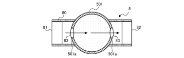
- FIG. 2 is a schematic configuration diagram of the optical sensor 8 according to Embodiment 1.
- FIG. FIG. 2 is a schematic cross-sectional view of the coolant pipe 501 cut in the radial direction with the optical sensor 8 attached to the coolant pipe 501 .
- the optical sensor 8 includes a housing 80 attached to the refrigerant pipe 501, and an illuminator 81 and a detector 82 provided within the housing 80.
- the irradiator 81 and the detector 82 are arranged to face each other with the refrigerant pipe 501 interposed therebetween.
- the irradiator 81 has a light source such as an LED that emits light of a specific wavelength, and irradiates light based on an instruction from the control device 200 .
- the detector 82 detects the light emitted from the irradiator 81 , converts the intensity of the detected light into an electrical signal, and transmits the electrical signal to the control device 200 .
- the refrigerant pipe 501 is provided with openings 501a at positions facing the irradiator 81 and the detector 82, respectively. Each opening 501 a is closed by a window plate 83 of the optical sensor 8 .
- the window plate 83 is made of a material that is transparent to the irradiated light and that can withstand the pressure of the working fluid within the operating range of the refrigeration cycle apparatus 100 . Before the refrigerant is sealed, the light emitted from the irradiator 81 passes through the refrigerant pipe 501 through the window plate 83 and is transmitted to the detector 82 .
- the control device 200 controls the operation of the refrigeration cycle device 100 as a whole.
- the control device 200 is composed of a computer having a memory that stores data and programs required for control and a CPU that executes the programs, dedicated hardware such as ASIC or FPGA, or both.
- FIG. 3 is a control block diagram of the refrigeration cycle apparatus 100 according to Embodiment 1.
- the control device 200 has a component concentration measurement section 201 , an operation control section 202 and a storage section 203 .
- the component concentration measurement unit 201 is a functional unit realized by the CPU of the control device 200 executing a program or by a dedicated processing circuit.
- the component concentration measuring unit 201 controls the illuminator 81 of the optical sensor 8 to emit light of a specific wavelength.
- the component concentration measurement unit 201 measures the concentration of the component contained in the working fluid of the refrigeration cycle device 100 based on the detection result of the detector 82 of the optical sensor 8 .
- the concentration of the components contained in the working fluid is, for example, the concentration of refrigerating machine oil contained in the refrigerant, or the concentration of each refrigerant that constitutes the non-azeotropic mixed refrigerant.
- the component concentration measurement unit 201 transmits the measured component concentration to the operation control unit 202 . The measurement of the component concentration of the working fluid by the component concentration measurement unit 201 will be detailed later.
- the operation control unit 202 is a functional unit realized by the CPU of the control device 200 executing a program or by a dedicated processing circuit.
- the operation control unit 202 controls each unit of the refrigeration cycle device 100 based on setting information input via a remote control (not shown) or the like and detection results of various sensors such as an indoor temperature sensor or an outdoor temperature sensor.
- the operation control unit 202 controls the operating frequency of the compressor 1, the opening degrees of the first expansion device 51 and the cooling expansion device 40, and the first fan 31 based on the setting information and the detection results of each temperature sensor. and the number of revolutions of the second fan 61 is controlled.
- the operation control unit 202 of the present embodiment controls the operation of the refrigeration cycle device 100 according to the component concentration of the working fluid measured by the component concentration measurement unit 201.
- the operation control unit 202 reduces the operating frequency of the compressor 1 in order to prevent the refrigerating machine oil from being depleted in the compressor 1, or The opening degree of the first throttle device 51 is decreased. As a result, the dryness of the refrigerant flowing out of the evaporator 6 is increased, and the inflow of liquid refrigerant into the compressor 1 is suppressed.
- the operation control unit 202 determines the circulation composition ratio from the concentration of each refrigerant contained in the non-azeotropic refrigerant mixture measured by the component concentration measurement unit 201. is calculated, and the evaporation saturation temperature is calculated from the circulation composition ratio. Then, if the temperature of the refrigerant flowing out of the evaporator 6 is equal to or lower than the evaporation saturation temperature, the operation control unit 202 lowers the frequency of the compressor 1 or reduces the opening degree of the first throttle device 51 . As a result, the dryness of the refrigerant flowing out of the evaporator 6 is increased, and the inflow of liquid refrigerant into the compressor 1 is suppressed.
- the operation control unit 202 may change the frequency of the compressor 1 and the opening degree of the first expansion device 51 according to the circulation composition ratio of the refrigerant, and increase the refrigerant temperature at the refrigerant inlet of the evaporator 6. .
- frost formation and freezing due to temperature drop of the evaporator 6 can be suppressed.
- the storage unit 203 is a volatile or nonvolatile memory such as RAM or ROM.
- the storage unit 203 stores programs for executing the functions of the component concentration measurement unit 201 and the operation control unit 202, and various data such as parameters and threshold values used in controlling each unit.
- the condenser 3 heat is exchanged between the high-temperature and high-pressure gas refrigerant that has flowed into the condenser 3 and the air supplied by the first fan 31 .
- the refrigerant heat-exchanged in the condenser 3 is condensed into a high-temperature and high-pressure liquid refrigerant or a gas-liquid two-phase refrigerant.
- the refrigerant flowing through the condensed fluid flow path 41 of the heat exchanger 4 between refrigerants is heat-exchanged with the refrigerant flowing through the low-pressure flow path 42 of the heat exchanger 4 between refrigerants, and is cooled to become liquid refrigerant.
- Condensed fluid flow path 41 exits.
- the liquid refrigerant that has flowed out of the condensed fluid flow path 41 of the heat exchanger between refrigerants 4 flows through the refrigerant pipe 501 and is partly branched to the branch pipe 502 .
- Liquid refrigerant flowing through the refrigerant pipe 501 passes through the optical sensor 8 .
- the liquid refrigerant that has passed through the optical sensor 8 is decompressed by the first expansion device 51 , becomes a low-pressure gas-liquid two-phase state, and flows into the evaporator 6 .
- heat is exchanged between the gas-liquid two-phase refrigerant flowing into the evaporator 6 and the air supplied by the second fan 61.
- the refrigerant evaporates into a low pressure gaseous refrigerant.
- the air cooled by this heat exchange is supplied to the space to be cooled, and the space to be cooled is cooled.
- the refrigerant branched to the branch pipe 502 is depressurized by the cooling expansion device 40, becomes a medium-pressure liquid refrigerant or a liquid-based gas-liquid two-phase refrigerant, and flows into the low-pressure flow path 42 of the heat exchanger 4 between refrigerants. do.
- the refrigerant flowing through the low-pressure flow path 42 of the refrigerant heat exchanger 4 exchanges heat with the refrigerant flowing through the condensed fluid flow path 41 to become a gas-liquid two-phase refrigerant or a low-pressure gas refrigerant.
- the low-pressure gas-liquid two-phase refrigerant or gas refrigerant that has flowed out of the low-pressure flow path 42 of the heat exchanger between refrigerants 4 flows through the refrigerant pipe 503 and joins the low-pressure gas refrigerant that has flowed out of the evaporator 6 .
- the low-pressure gas refrigerant flowing out of the evaporator 6 joins the refrigerant flowing out of the low-pressure flow path 42 of the heat exchanger between refrigerants 4 and flows into the refrigerant tank 7 . After that, the gas refrigerant separated in the refrigerant tank 7 is sucked into the compressor 1, compressed again by the compressor 1, and discharged. This cycle is repeated in the refrigeration cycle device 100 .
- the irradiator 81 of the optical sensor 8 emits light having a wavelength designed according to the components forming the working fluid based on the instruction from the component concentration measurement unit 201 of the control device 200 .
- Components that make up the working fluid are refrigerant and refrigerating machine oil.
- the light emitted from the irradiator 81 irradiates the working fluid flowing through the refrigerant pipe 501 .
- the working fluid absorbs light according to the wavelength sensitivity of the absorbance that differs for each component, and residual light is transmitted through the window plate 83 and detected by the detector 82 .
- the detector 82 detects the intensity of transmitted light for each wavelength and transmits the detected intensity of transmitted light to the control device 200 .
- the component concentration measurement unit 201 of the control device 200 obtains the transmittance T from the intensity of the irradiation light emitted from the irradiator 81 and the intensity of the transmitted light detected by the detector 82, and calculates the concentration of the component contained in the working fluid. measure.
- the component concentration measuring unit 201 measures the concentration of the refrigerating machine oil from the transmittance T of the wavelength corresponding to the type of oil in the ultraviolet region of wavelength 380 nm or less where the refrigerating machine oil has a strong absorption wavelength.
- the component concentration measurement unit 201 measures the wavelength transmittance T according to the type of refrigerant in the infrared region of 780 nm or more, where olefinic refrigerants, ethylene refrigerants, or ethane refrigerants have strong absorption wavelengths. Measure the concentration of the refrigerant.
- the component concentration measurement unit 201 calculates the component concentration using the Beer-Lambert law represented by the following equation (1).
- T is the transmittance
- A is the absorbance
- ⁇ ( ⁇ i ) is the component-specific absorption
- c is the concentration
- l is the optical path length through the working fluid.
- l is the diameter of refrigerant pipe 501 . Since the transmittance T, the component-specific absorptivity ⁇ ( ⁇ i ), and the optical path length l are known, the concentration c is determined from equation (1).
- FIG. 4 is a graph showing an example of absorption characteristics of two components contained in the working fluid.
- the solid line indicates the absorption characteristics of the first component C1
- the dashed line indicates the absorption characteristics of the second component C2.
- the first component C1 and the second component C2 are components contained in the working fluid, and are, for example, a refrigerant and refrigerating machine oil, or two refrigerants forming a mixed refrigerant.
- the component concentration measuring unit 201 uses the absorption wavelength of the first component C1 instead of the third wavelength ⁇ 3, which is the same absorption wavelength of the first component C1 and the second component C2, as the wavelength of the light emitted by the irradiator 81.
- a first wavelength ⁇ 1 that is not the absorption wavelength of the second component C2 and a second wavelength ⁇ 2 that is the absorption wavelength of the second component C2 but not the absorption wavelength of the first component C1 are set.
- the optical sensor 8 can accurately measure the transmitted light of each component.
- the fourth wavelength ⁇ 4 which is not absorbed by both the first component C1 and the second component C2, as the reference light, the decrease in the light intensity of the detection light due to factors other than the absorption of the components contained in the working fluid can be prevented. The influence on measurement can be reduced.
- the component concentration measurement unit 201 may calculate the component concentration of the working fluid by the following equation (2) using the transmittance T0 of the reference light and the transmittance Ti of the measurement light.
- the component concentration measurement unit 201 can calculate the component concentrations from the plurality of wavelengths using Equation (3) below.
- FIG. 5 is a diagram for explaining transmitted light detection of working fluid in a conventional example.
- the conventional example of FIG. 5 is an example in which the refrigerating cycle device 100 does not have the refrigerant heat exchanger 4 between the condenser 3 and the optical sensor 8 .
- the refrigerant flowing through the refrigerant pipe 501 provided with the optical sensor 8 becomes gas-liquid.
- a two-phase state is established.
- a gas-liquid interface V is formed by the working fluid in the refrigerant pipe 501, and the light emitted from the optical sensor 8 is reflected and refracted at the gas-liquid interface V and scattered. decreases the intensity of transmitted light detected at .
- the volume ratio of the measurement area what can be measured by optical measurement using the optical sensor 8 is the volume ratio of the measurement area. If the velocity of the fluid is constant in a single-phase fluid, the component ratio can be measured as substantially the same as the volume ratio. On the other hand, in the case of a two-phase fluid, the gas flow rate and the liquid flow rate are different, and the component ratio of the liquid phase is the ratio of (gas component velocity ⁇ gas component volume+liquid component velocity ⁇ liquid component volume). Since it is generally difficult to measure the gas flow velocity and the liquid flow velocity, the detection accuracy of the detector 82 decreases when the working fluid flowing through the refrigerant pipe 501 is a two-phase fluid.
- heat exchange between the high-temperature refrigerant flowing out of the condenser 3 and the low-temperature refrigerant is performed between the condenser 3 and the optical sensor 8 to convert the high-temperature refrigerant into a liquid refrigerant.
- a exchanger 4 is provided.
- the working fluid flowing through the refrigerant pipe 501 provided with the optical sensor 8 is reliably brought into a liquid state (single-phase state), so that the gas-liquid interface V is not formed inside the refrigerant pipe 501 .
- the detection accuracy of the light transmitted through the working fluid in the optical sensor 8 is improved, and the measurement accuracy of the component concentration of the working fluid is also improved.
- the refrigeration cycle apparatus 100 of the present embodiment includes the optical sensor 8 in the same unit (the heat source unit 10 in the present embodiment) as the unit including the heat exchanger between refrigerants 4 .
- the optical sensor 8 is arranged in a unit different from the unit provided with the heat exchanger 4 between refrigerants, the gas-liquid two-phase working fluid due to pressure loss in the refrigerant pipe 501 connecting the units is suppressed. It is more effective because it can
- FIG. 6 is a refrigerant circuit diagram of a refrigeration cycle device 100A according to Embodiment 2.
- a refrigeration cycle apparatus 100A of Embodiment 2 is a hot water supply apparatus that supplies hot water or a hot water heating apparatus that performs heating using hot water.
- Solid line arrows in FIG. 6 indicate the flow of coolant, and broken line arrows indicate the flow of water.
- FIG. 6 only a part of the water circuit 300 is shown for simplification.
- the refrigeration cycle device 100A consists of a heat source unit 10A and a load unit 20A.
- the heat source unit 10A and the load unit 20A each have an individual housing and are installed in different places such as outdoors and indoors.
- the heat source unit 10A includes a compressor 1, a refrigerant heat exchanger 4, a cooling expansion device 40, an optical sensor 8, a first expansion device 51, an evaporator 6, a second fan 61, and a refrigerant tank. 7 and a control device 200 .
- the load unit 20A includes a condenser 3A and a pump 32.
- Compressor 1, refrigerant heat exchanger 4, cooling expansion device 40, first expansion device 51, evaporator 6, second fan 61, refrigerant tank 7, optical sensor 8, and control device 200 in heat source unit 10A and functions are the same as those of the first embodiment.
- the condenser 3A in the load unit 20A is a shell-and-tube heat exchanger, a heat pipe heat exchanger, or a double-pipe heat exchanger that exchanges heat between the refrigerant flowing in the refrigerant circuit and the water flowing in the water circuit 300. , or a plate heat exchanger.
- the pump 32 circulates water flowing through the water circuit 300 .
- the pump 32 has an inverter circuit (not shown), and can change the water flow rate during transportation by changing the driving rotation speed according to an instruction from the control device 200 .
- the condenser 3A heat is exchanged between the high-temperature, high-pressure gas refrigerant that has flowed into the condenser 3A and the water that flows through the water circuit 300.
- the refrigerant heat-exchanged in the condenser 3A is condensed into a high-pressure liquid refrigerant or a gas-liquid two-phase refrigerant.
- the water heated by heat exchange with the refrigerant in the condenser 3A is used for hot water supply or hot water heating.
- the high-pressure liquid refrigerant or gas-liquid two-phase refrigerant that has flowed out of the condenser 3A flows into the condensed fluid flow path 41 of the heat exchanger between refrigerants 4 .
- the flow of the refrigerant after the heat exchanger 4 between refrigerants is the same as in the first embodiment.
- the high-temperature refrigerant flowing out of the condenser 3A is heat-exchanged with the low-temperature refrigerant between the condenser 3A and the optical sensor 8 to convert the refrigerant into liquid refrigerant.
- An intermediate heat exchanger 4 is provided.
- FIG. 7 is a refrigerant circuit diagram of a refrigeration cycle device 100B according to Embodiment 3. As shown in FIG. As shown in FIG. 7, a refrigeration cycle apparatus 100B of Embodiment 3 differs from Embodiment 1 in that a heat source unit 10B includes a second expansion device 52. As shown in FIG. Other configurations are the same as those of the first embodiment.
- the second expansion device 52 is provided between the condenser 3 and the refrigerant heat exchanger 4, and expands the refrigerant flowing out of the condenser 3 to reduce the pressure.
- the second throttle device 52 is, for example, an electronic expansion valve whose opening can be controlled.
- the second expansion device 52 is not limited to an electronic expansion valve, and may be a mechanical expansion valve employing a diaphragm as a pressure receiving portion, a capillary tube, or the like.
- the opening degree of the second throttle device 52 is controlled by the operation control section 202 of the control device 200 .
- the pressure of the working fluid flowing through the refrigerant pipe 501 provided with the optical sensor 8 can be controlled.
- the operation control unit 202 controls the opening degree of the second expansion device 52 according to the operation of the refrigeration cycle device 100B.
- the refrigerant pipe 501 is provided with a pressure sensor (not shown) for measuring the pressure of the working fluid flowing through the refrigerant pipe 501. 52 opening is controlled.
- the allowable range is a range in which detection failure of the optical sensor 8 does not occur.
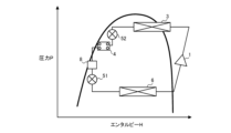
- FIG. 8 is a Mollier diagram when the refrigerant flowing through the refrigerant pipe 501 is in a gas-liquid two-phase state due to the pressure loss of the second expansion device 52 .
- a gas-liquid interface V is formed in the refrigerant pipe 501 as in the conventional example shown in FIG.
- the component concentration measurement unit 201 of the control device 200 notifies the operation control unit 202 of the occurrence of the detection failure.
- the operation control unit 202 decreases the opening degree of the first diaphragm device 51 and increases the opening degree of the second diaphragm device 52 when it is notified that the detection failure of the optical sensor 8 has occurred.
- FIG. 9 is a Mollier diagram of the refrigeration cycle device 100B according to the third embodiment.
- the opening degrees of the first expansion device 51 and the second expansion device 52 as described above, the temperature difference between the high-temperature refrigerant and the low-temperature refrigerant in the heat exchanger between refrigerants 4 is increased, and the cooling of the high-temperature refrigerant is promoted. can do.
- the refrigerant flowing through the refrigerant pipe 501 can be brought into a liquid state as shown in the Mollier diagram shown in FIG.
- the working fluid flowing through the refrigerant pipe 501 provided with the optical sensor 8 is reliably brought into a liquid state, so that the gas-liquid interface V is not formed inside the refrigerant pipe 501 .
- the detection accuracy of the light transmitted through the working fluid in the optical sensor 8 is improved, and the measurement accuracy of the component concentration of the working fluid is also improved.
- FIG. 10 is a refrigerant circuit diagram of a refrigeration cycle device 100C according to Embodiment 4. As shown in FIG. A refrigeration cycle device 100C of Embodiment 3 is an air conditioner that cools and heats a space to be air-conditioned.
- the refrigeration cycle device 100C consists of a heat source unit 10C and a load unit 20C.
- the heat source unit 10C is an outdoor unit of the air conditioner, and the load unit 20C is an indoor unit of the air conditioner.
- the heat source unit 10C includes a compressor 1, a flow path switching valve 2, an outdoor heat exchanger 30, a first fan 31, a second expansion device 52, a flow path switching mechanism 9, and a refrigerant heat exchanger 4. , a cooling throttle device 40 , an optical sensor 8 , a coolant tank 7 , and a control device 200 .
- the load unit 20 ⁇ /b>C includes a first expansion device 51 , an indoor heat exchanger 60 and a second fan 61 .
- the configurations and functions of the compressor 1, the first fan 31, the refrigerant heat exchanger 4, the cooling expansion device 40, the optical sensor 8, the refrigerant tank 7, and the control device 200 in the heat source unit 10C are the same as those in the first embodiment. be. Also, the configurations and functions of the first expansion device 51 and the second fan 61 in the load unit 20C are the same as those of the first embodiment.
- the flow path switching valve 2 is, for example, a four-way valve that switches the flow path of the refrigerant discharged from the compressor 1.
- the control device 200 performs heating operation or cooling operation by switching the state of the flow path switching valve 2 .
- the flow path switching valve 2 connects the discharge port of the compressor 1 and the refrigerant inlet of the outdoor heat exchanger 30 and connects the suction port of the compressor 1 and the indoor heat exchanger 60 during cooling operation.
- the refrigerant flow is switched to connect with the refrigerant outlet.
- the flow path switching valve 2 connects the discharge port of the compressor 1 and the refrigerant inlet of the indoor heat exchanger 60, and connects the suction port of the compressor 1 and the refrigerant outlet of the outdoor heat exchanger 30. switch the refrigerant flow to connect the
- the outdoor heat exchanger 30 functions as an evaporator during heating operation, exchanges heat between the refrigerant that has flowed into the interior and the outdoor air, and evaporates the refrigerant.
- the outdoor heat exchanger 30 functions as a condenser during cooling operation, performs heat exchange between the refrigerant that has flowed inside and the outdoor air, and condenses and liquefies the refrigerant.
- a first fan 31 is arranged adjacent to the outdoor heat exchanger 30 in order to increase the efficiency of heat exchange between the refrigerant and the air in the outdoor heat exchanger 30 .
- the indoor heat exchanger 60 functions as a condenser during heating operation, exchanges heat between the refrigerant that has flowed into the interior and the indoor air, and condenses and liquefies the refrigerant.
- the indoor heat exchanger 60 functions as an evaporator during cooling operation, performs heat exchange between the refrigerant that has flowed inside and the air, and evaporates the refrigerant.
- a second fan 61 is arranged adjacent to the indoor heat exchanger 60 in order to increase the efficiency of heat exchange between the refrigerant and the air in the indoor heat exchanger 60 .
- the outdoor heat exchanger 30 and the indoor heat exchanger 60 are, for example, fin-and-tube heat exchangers or microchannel heat exchangers.
- the outdoor heat exchanger 30 and the indoor heat exchanger 60 are, for example, a shell-and-tube heat exchanger that exchanges heat between a heat medium such as water or brine and a refrigerant, a heat pipe heat exchanger, a double A tubular heat exchanger, a plate heat exchanger, or the like may be used.
- the second expansion device 52 expands the refrigerant flowing out of the outdoor heat exchanger 30 to reduce the pressure.
- the second throttle device 52 is, for example, an electronic expansion valve whose opening can be controlled.
- the second expansion device 52 is not limited to an electronic expansion valve, and may be a mechanical expansion valve employing a diaphragm as a pressure receiving portion, a capillary tube, or the like.
- the opening degree of the second throttle device 52 is controlled by the operation control section 202 of the control device 200 .
- the flow path switching mechanism 9 the refrigerant heat exchanger 4 is arranged between the heat exchanger functioning as a condenser and the optical sensor 8 regardless of whether the refrigeration cycle device 100C performs cooling operation or heating operation.
- the flow of the refrigerant is switched as follows.
- the flow path switching mechanism 9 of this embodiment includes a first check valve 91 , a second check valve 92 , a third check valve 93 and a fourth check valve 94 .
- the first check valve 91 is provided in the refrigerant pipe 504 that connects the outdoor heat exchanger 30 and the refrigerant inlet of the condensed fluid flow path 41 of the heat exchanger 4 between refrigerants.
- the first check valve 91 allows the flow of refrigerant from the outdoor heat exchanger 30 to the condensed fluid flow path 41 of the heat exchanger 4 between refrigerants, and allows the flow of the outdoor heat from the condensed fluid flow path 41 of the heat exchanger 4 between refrigerants. Refrigerant flow to the exchanger 30 is cut off.
- the second check valve 92 is provided between the optical sensor 8 of the refrigerant pipe 501 and the first throttle device 51 .
- the second check valve 92 allows the flow of refrigerant from the optical sensor 8 to the first expansion device 51 and blocks the flow of refrigerant from the first expansion device 51 to the optical sensor 8 .
- the third check valve 93 is provided in the refrigerant pipe 505 that connects the first expansion device 51 and the refrigerant inlet of the condensed fluid flow path 41 of the heat exchanger between refrigerants 4 .
- the third check valve 93 allows the refrigerant to flow from the first expansion device 51 to the condensed fluid flow path 41 of the heat exchanger related to refrigerant 4, and allows the refrigerant to flow from the condensed fluid flow path 41 of the heat exchanger related to refrigerant 4 to the first flow path. Refrigerant flow to the expansion device 51 is cut off.
- the fourth check valve 94 branches from between the optical sensor 8 and the second check valve 92 in the refrigerant pipe 501 and is connected between the outdoor heat exchanger 30 in the refrigerant pipe 504 and the first check valve 91. It is provided in the branch pipe 506 where the The fourth check valve 94 allows the flow of refrigerant from the optical sensor 8 to the outdoor heat exchanger 30 and blocks the flow of refrigerant from the outdoor heat exchanger 30 to the optical sensor 8 .
- FIG. 11 is a diagram illustrating the flow of refrigerant during cooling operation of the refrigeration cycle device 100C according to Embodiment 4.
- FIG. 11 some flow paths of the refrigerant circuit diagram of FIG. 10 are omitted for ease of viewing. Solid arrows in FIG. 11 indicate the flow of the coolant.
- the control device 200 fully opens the second throttle device 52 . Therefore, in FIG. 11, illustration of the second diaphragm device 52 is omitted.
- the outdoor heat exchanger 30 functions as a condenser, and heat exchange is performed between the high-temperature and high-pressure gas refrigerant that has flowed inside and the air supplied by the first fan 31 .
- the refrigerant heat-exchanged in the outdoor heat exchanger 30 is condensed into a high-pressure liquid refrigerant or gas-liquid two-phase refrigerant.
- the high-temperature and high-pressure liquid refrigerant or gas-liquid two-phase refrigerant that has flowed out of the outdoor heat exchanger 30 passes through the first check valve 91 and flows into the condensed fluid flow path 41 of the heat exchanger between refrigerants 4 .
- the refrigerant flowing through the condensed fluid flow path 41 of the heat exchanger 4 between refrigerants is heat-exchanged with the refrigerant flowing through the low-pressure flow path 42 of the heat exchanger 4 between refrigerants, and is cooled to become liquid refrigerant.
- Condensed fluid flow path 41 exits.
- the liquid refrigerant that has flowed out of the condensed fluid flow path 41 of the heat exchanger between refrigerants 4 flows through the refrigerant pipe 501 and is partly branched to the branch pipe 502 .
- Liquid refrigerant flowing through the refrigerant pipe 501 passes through the optical sensor 8 .
- the liquid refrigerant that has passed through the optical sensor 8 passes through the second check valve 92 and is decompressed by the first throttle device 51 , becomes a low-pressure gas-liquid two-phase state, and flows into the indoor heat exchanger 60 .
- the indoor heat exchanger 60 functions as an evaporator, and heat is exchanged between the gas-liquid two-phase refrigerant that has flowed into the indoor heat exchanger 60 and the air supplied by the second fan 61.
- the liquid refrigerant evaporates to become a low-pressure gas refrigerant.
- the air cooled by this heat exchange is supplied to the air-conditioned space, and the air-conditioned space is cooled.
- the refrigerant branched to the branch pipe 502 is depressurized by the cooling expansion device 40, becomes a medium-pressure liquid refrigerant or a liquid-based gas-liquid two-phase refrigerant, and flows into the low-pressure flow path 42 of the heat exchanger 4 between refrigerants. do.
- the refrigerant flowing through the low-pressure flow path 42 of the refrigerant heat exchanger 4 exchanges heat with the refrigerant flowing through the condensed fluid flow path 41 to become a gas-liquid two-phase refrigerant or a low-pressure gas refrigerant.
- the low-pressure gas-liquid two-phase refrigerant or gas refrigerant that has flowed out of the low-pressure flow path 42 of the heat exchanger between refrigerants 4 flows through the refrigerant pipe 503 and joins the low-pressure gas refrigerant that has flowed out of the indoor heat exchanger 60 .
- the low-pressure gas refrigerant flowing out of the indoor heat exchanger 60 joins the refrigerant flowing out of the low-pressure flow path 42 of the heat exchanger between refrigerants 4 and flows into the refrigerant tank 7 . After that, the gas refrigerant separated in the refrigerant tank 7 is sucked into the compressor 1, compressed again by the compressor 1, and discharged.
- FIG. 12 is a diagram explaining the flow of the refrigerant during the heating operation of the refrigeration cycle device 100C according to Embodiment 4.
- FIG. 12 some flow paths of the refrigerant circuit diagram of FIG. 10 are omitted for ease of viewing. Solid arrows in FIG. 12 indicate the flow of the coolant.
- the control device 200 fully opens the first expansion device 51 . Therefore, in FIG. 12, illustration of the first diaphragm device 51 is omitted.
- the compressor 1 When the compressor 1 of the refrigeration cycle device 100C is driven, the compressor 1 discharges high-temperature, high-pressure gas refrigerant.
- the high-temperature, high-pressure gas refrigerant discharged from the compressor 1 flows through the flow path switching valve 2 into the indoor heat exchanger 60 .
- the indoor heat exchanger 60 functions as a condenser, and heat exchange is performed between the high-temperature and high-pressure gas refrigerant that has flowed inside and the air supplied by the second fan 61 .
- the refrigerant heat-exchanged in the indoor heat exchanger 60 is condensed into a high-pressure liquid refrigerant or a gas-liquid two-phase refrigerant.
- the air heated by this heat exchange is supplied to the air-conditioned space, and the air-conditioned space is heated.
- the high-temperature and high-pressure liquid refrigerant or gas-liquid two-phase refrigerant that has flowed out of the indoor heat exchanger 60 passes through the refrigerant pipe 505 and the third check valve 93 and flows into the condensed fluid flow path 41 of the heat exchanger 4 between refrigerants.
- the refrigerant flowing through the condensed fluid flow path 41 of the heat exchanger 4 between refrigerants is heat-exchanged with the refrigerant flowing through the low-pressure flow path 42 of the heat exchanger 4 between refrigerants, and is cooled to become liquid refrigerant. Condensed fluid flow path 41 exits.
- the liquid refrigerant that has flowed out of the condensed fluid flow path 41 of the heat exchanger between refrigerants 4 flows through the refrigerant pipe 501 and is partly branched to the branch pipe 502 .
- Liquid refrigerant flowing through the refrigerant pipe 501 passes through the optical sensor 8 .
- the liquid refrigerant that has passed through the optical sensor 8 passes through the branch pipe 506 and the fourth check valve 94, is decompressed by the second expansion device 52, becomes a low-pressure gas-liquid two-phase state, and flows into the outdoor heat exchanger 30. .
- the outdoor heat exchanger 30 functions as an evaporator, and heat is exchanged between the gas-liquid two-phase refrigerant that has flowed into the outdoor heat exchanger 30 and the air supplied by the first fan 31.
- the liquid refrigerant evaporates to become a low-pressure gas refrigerant.
- the refrigerant branched to the branch pipe 502 is depressurized by the cooling expansion device 40, becomes a medium-pressure liquid refrigerant or a liquid-based gas-liquid two-phase refrigerant, and flows into the low-pressure flow path 42 of the heat exchanger 4 between refrigerants. do.
- the refrigerant flowing through the low-pressure flow path 42 of the refrigerant heat exchanger 4 exchanges heat with the refrigerant flowing through the condensed fluid flow path 41 to become a gas-liquid two-phase refrigerant or a low-pressure gas refrigerant.
- the low-pressure gas-liquid two-phase refrigerant or gas refrigerant that has flowed out of the low-pressure flow path 42 of the heat exchanger between refrigerants 4 flows through the refrigerant pipe 503 and joins the low-pressure gas refrigerant that has flowed out of the outdoor heat exchanger 30 .
- the low-pressure gas refrigerant flowing out of the outdoor heat exchanger 30 joins the refrigerant flowing out of the low-pressure flow path 42 of the heat exchanger between refrigerants 4 and flows into the refrigerant tank 7 . After that, the gas refrigerant separated in the refrigerant tank 7 is sucked into the compressor 1, compressed again by the compressor 1, and discharged.
- the heat exchanger between refrigerants is provided between the heat exchanger functioning as a condenser and the optical sensor 8 during both the cooling operation and the heating operation. 4 is provided. Therefore, as in the first embodiment, it is possible to improve the measurement accuracy of the component concentration of the working fluid in the refrigeration cycle device 100C.
- the flow path switching mechanism 9 is not limited to a configuration consisting of four check valves.
- the flow switching mechanism 9 may switch the refrigerant flow path so that the optical sensor 8 is arranged downstream of the condensed fluid flow path 41 of the heat exchanger between refrigerants 4 in both the cooling operation and the heating operation.
- a four-way valve or the like may be used.
- FIG. 13 is a refrigerant circuit diagram of a refrigeration cycle device 100D according to Embodiment 5. As shown in FIG. A refrigeration cycle device 100D of the present embodiment is an air conditioner that cools and heats a plurality of air-conditioned spaces.
- a refrigeration cycle apparatus 100D includes a heat source unit 10D, a relay unit 15, and a plurality of load units 21D and 22D.
- the heat source unit 10D, the relay unit 15, and the plurality of load units 21D and 22D have individual housings and are installed in different locations such as outdoors and indoors.
- the heat source unit 10D includes a compressor 1, a first condenser 3B, a first fan 31, and a refrigerant tank 7.
- the relay unit 15 includes a refrigerant heat exchanger 4 , a cooling throttle device 40 , an optical sensor 8 , a control device 200 , a branch portion 45 and a third throttle device 53 .
- the load unit 21D includes a first expansion device 51, an evaporator 6, and a second fan 61.
- the load unit 22 ⁇ /b>D includes a second condenser 3 ⁇ /b>C, a fourth expansion device 54 and a first fan 31 .
- the compressor 1 of the refrigeration cycle device 100D, the refrigerant heat exchanger 4, the cooling expansion device 40, the first expansion device 51, the evaporator 6, the second fan 61, the refrigerant tank 7, the optical sensor 8, and the control device 200 The configuration and functions are the same as those of the first embodiment.
- the configuration and function of the first condenser 3B and the second condenser 3C are the same as the condenser 3 of the first embodiment.
- the branching portion 45 branches the inflowing refrigerant to the load unit 21D and the load unit 22D.
- the branching unit 45 is, for example, a gas-liquid separator, which causes refrigerant containing a large amount of gas phase to flow into the second condenser 3C of the load unit 22D, and flows refrigerant containing a large amount of liquid phase into the evaporator 6 of the load unit 21D. connected to the load units 21D and 22D so as to allow the
- the third expansion device 53 expands the refrigerant flowing out from the branch portion 45 to reduce the pressure.
- the fourth expansion device 54 expands and decompresses the refrigerant that has flowed out of the second condenser 3C.
- the third throttle device 53 and the fourth throttle device 54 are, for example, electronic expansion valves whose opening can be controlled.
- the third expansion device 53 and the fourth expansion device 54 are not limited to electronic expansion valves, and may be mechanical expansion valves employing diaphragms in pressure receiving portions, capillary tubes, or the like.
- the opening degrees of the third throttle device 53 and the fourth throttle device 54 are controlled by the operation control section 202 of the control device 200 .
- first condenser 3B heat is exchanged between the high-temperature and high-pressure gas refrigerant that has flowed into the first condenser 3B and the air supplied by the first fan 31.
- the refrigerant heat-exchanged in the first condenser 3B is condensed into a high-temperature, high-pressure gas-liquid two-phase refrigerant.
- the gas-liquid two-phase refrigerant that has flowed into the branch portion 45 is separated into gas refrigerant and liquid refrigerant, and the gas refrigerant flows into the second condenser 3C.
- heat exchange is performed between the high-temperature and high-pressure gas refrigerant that has flowed into the second condenser 3 ⁇ /b>C and the air supplied by the first fan 31 .
- the refrigerant heat-exchanged in the second condenser 3C is condensed into a high-temperature, high-pressure liquid refrigerant.
- the air heated by this heat exchange is supplied to the air-conditioned space provided with the load unit 22D, and the air-conditioned space is heated.
- the high-temperature, high-pressure liquid refrigerant that has flowed out of the second condenser 3C is decompressed by the fourth expansion device 54 and flows into the condensed fluid flow path 41 of the heat exchanger 4 between refrigerants.
- the refrigerant flowing through the condensed fluid flow path 41 of the heat exchanger 4 between refrigerants is heat-exchanged with the refrigerant flowing through the low-pressure flow path 42 of the heat exchanger 4 between refrigerants, and is cooled to become liquid refrigerant.
- Condensed fluid flow path 41 exits.
- the liquid refrigerant that has flowed out of the condensed fluid flow path 41 of the heat exchanger between refrigerants 4 joins the liquid refrigerant that has flowed out of the branch portion 45 and has been depressurized by the third expansion device 53, and flows through the refrigerant pipe 501.
- the flow is branched to the branch pipe 502 .
- Liquid refrigerant flowing through the refrigerant pipe 501 passes through the optical sensor 8 .
- the liquid refrigerant that has passed through the optical sensor 8 is decompressed by the first expansion device 51 , becomes a low-pressure gas-liquid two-phase state, and flows into the evaporator 6 .
- heat is exchanged between the gas-liquid two-phase refrigerant flowing into the evaporator 6 and the air supplied by the second fan 61.
- the refrigerant evaporates into a low pressure gaseous refrigerant.
- the air cooled by this heat exchange is supplied to the air-conditioned space provided with the load unit 21D, and the air-conditioned space is cooled.
- the refrigerant branched to the branch pipe 502 is depressurized by the cooling expansion device 40, becomes a medium-pressure liquid refrigerant or a liquid-based gas-liquid two-phase refrigerant, and flows into the low-pressure flow path 42 of the heat exchanger 4 between refrigerants. do.
- the refrigerant flowing through the low-pressure flow path 42 of the refrigerant heat exchanger 4 exchanges heat with the refrigerant flowing through the condensed fluid flow path 41 to become a gas-liquid two-phase refrigerant or a low-pressure gas refrigerant.
- the low-pressure gas-liquid two-phase refrigerant or gas refrigerant that has flowed out of the low-pressure flow path 42 of the heat exchanger between refrigerants 4 flows through the refrigerant pipe 503 and joins the low-pressure gas refrigerant that has flowed out of the evaporator 6 .
- the low-pressure gas refrigerant flowing out of the evaporator 6 joins the refrigerant flowing out of the low-pressure flow path 42 of the heat exchanger between refrigerants 4 and flows into the refrigerant tank 7 . After that, the gas refrigerant separated in the refrigerant tank 7 is sucked into the compressor 1, compressed again by the compressor 1, and discharged. This cycle is repeated in the refrigeration cycle device 100 .
- the optical sensor 8 is mounted on the relay unit 15 as in the refrigeration cycle device 100D of the present embodiment, the measurement accuracy of the component concentration of the working fluid in the refrigeration cycle device 100D is improved as in the first embodiment. be able to. That is, the optical sensor 8 may be provided between the refrigerant outlet of the condensed fluid flow path 41 of the heat exchanger related to refrigerant 4 and the first expansion device 51, and the mounted unit is not limited.
- the heat exchangers mounted on a plurality of heat load units include both evaporators and condensers, the heat exchangers that operate as evaporators It becomes possible to measure the component concentration of the flowing working fluid.
- the refrigeration cycle device 100D when the refrigeration cycle device 100D includes a plurality of condensers, a surplus refrigerant is generated compared to the case where the number of condensers is one, and the inlet of the compressor 1 is superheated. or become gas-liquid two-phase.
- the optical sensor 8 is placed between the condenser and the first throttle device to measure the component concentration of the working fluid and control the operation, thereby achieving both quality and performance improvement. .
- the number of optical sensors 8 and refrigerant heat exchangers 4 included in the refrigeration cycle device 100D may be two or more.
- the number of load units 21D and the number of load units 22D provided in the refrigeration cycle apparatus 100D are not limited to the example of FIG. 13, and may be plural.
- FIG. 14 is a refrigerant circuit diagram of a refrigeration cycle device 100E according to Modification 1.
- the refrigerant inlet of the low-pressure flow path 42 of the heat exchanger between refrigerants 4A is connected to the refrigerant outlet of the evaporator 6, and the refrigerant outlet of the low-pressure flow path 42 is connected to the refrigerant tank via the refrigerant pipe 503. 7 may be used.
- the branch pipe 502 and the cooling throttle device 40 can be omitted.
- the refrigerant flowing through the refrigerant pipe 501 provided with the optical sensor 8 can be in a liquid state, and the same effect as in the first embodiment can be obtained.
- FIG. 15 is a schematic diagram showing the installation direction of the optical sensor 8 of the refrigeration cycle apparatus according to Modification 2.
- the modified optical sensor 8 is attached to the refrigerant pipe 501 so that the acute angle ⁇ 1 between the direction of the light emitted from the irradiator 81 and the plane perpendicular to the direction of gravity is less than 45°.
- the optical sensor 8 is attached to the refrigerant pipe 501 so that the acute angle ⁇ 1 between the direction of the light emitted from the irradiator 81 and the plane perpendicular to the direction of gravity is less than 30°.
- FIG. 16 is a diagram for explaining the state of the working fluid when the flow velocity is low.
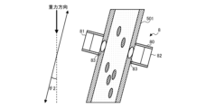
- FIG. 17 is a schematic diagram showing the installation direction of the optical sensor 8 of the refrigeration cycle apparatus according to Modification 3.
- the refrigerant pipe 501 in which the modified optical sensor 8 is installed is installed so that the acute angle ⁇ 2 formed by the extending direction of the refrigerant pipe 501 and the direction of gravity is smaller than 45°. More desirably, the refrigerant pipe 501 in which the optical sensor 8 is installed is installed so that the acute angle ⁇ 2 formed by the extending direction of the refrigerant pipe 501 and the direction of gravity is less than 30°.
- the angle formed between the direction of flow of the refrigerant in the refrigerant pipe 501 and the direction of gravity is reduced, so the component of the flow of refrigerant in the direction of gravity is increased.
- the separation due to the density difference of the refrigerant can be suppressed, and the symmetry of the component distribution in the cross-sectional direction of the flow path can be secured.
- deterioration in detection accuracy of transmitted light is suppressed, and measurement accuracy of component concentration of the working fluid is improved.
- the detection accuracy of the transmitted light and the measurement accuracy of the component concentration are improved.
- FIG. 18 is a refrigerant circuit diagram of a refrigeration cycle device 100F according to Modification 4.
- a temperature sensor 801 and a pressure sensor 802 may be provided in the refrigerant pipe 501 of the refrigeration cycle device 100F to measure the temperature and pressure of the working fluid flowing through the refrigerant pipe 501.
- the component concentration measuring unit 201 of the control device 200 the measured temperature and pressure and a table containing preset correction values may be used to correct the component concentration.
- the circulation composition ratio of the working fluid may be affected by refrigerant leakage during refrigerant charging during installation or refrigerant in the refrigerant tank 7 that changes according to operation. It varies greatly depending on the retention amount.
- the composition ratio of the working fluid may be predicted to control the frequency of the compressor 1 or the degree of opening of the first throttle device 51.
- FIG. In this case, a model learned in advance based on the absorbance, temperature and pressure of the components contained in the working fluid is stored in the storage unit 203 of the control device 200 .
- control device 200 receives the absorbance measured by the optical sensor 8, the temperature sensor 801, and the pressure sensor 802, the refrigerant temperature, and the refrigerant pressure as inputs, and outputs the circulation composition ratio of the working fluid using a learning model. good.
- the control device 200 reduces the opening of the second expansion device 52 . Further, when the refrigerant pressure measured by the pressure sensor 802 is lower than the learning range of the learning model and the measurement accuracy of the component concentration is lowered, the control device 200 increases the opening of the second expansion device 52 . This improves the measurement accuracy of the component concentration.
- the threshold used for determining whether to change the degree of opening of the second throttle device 52 is a design value set according to the pressure range of the learning model.
- FIG. 19 is a refrigerant circuit diagram of a refrigeration cycle device 100G according to Modification 5.
- a refrigeration cycle apparatus 100G of Modification 5 includes a heat source unit 10G, a load unit 21G, and a load unit 22G.
- the heat source unit 10G includes a compressor 1, a flow path switching valve 2, an outdoor heat exchanger 30, a first fan 31, a first expansion device 51, a heat exchanger between refrigerants 4, and a cooling expansion device 40. , an optical sensor 8 , a coolant tank 7 , and a control device 200 .
- the load unit 21G and the load unit 22G each include an indoor heat exchanger 60G and a second fan 61.
- an optical sensor 8 may be provided between the condenser and the throttling device provided downstream of the condenser.
- the heat exchangers that function as condensers in the heating operation are two indoor heat exchangers 60G, and the heat exchangers that function as condensers in the cooling operation are the outdoor heat exchangers 30.
- the refrigerant heat exchanger 4 is provided between the indoor heat exchanger 60G and the first expansion device 51 provided downstream of the indoor heat exchanger 60G, which is a condenser, during heating operation.
- An optical sensor 8 is provided downstream of the device 4 . Even if another throttle device is provided between the refrigerant heat exchanger 4 and the condenser, the effect is not hindered.
- the refrigeration cycle device 100G which can switch between cooling operation and heating operation, is generally designed with an amount of refrigerant for operation in which a large amount of refrigerant is required. As shown in FIG. 19, in a device that connects one heat source unit and multiple load units, in cooling operation with a large number of evaporators, the refrigerant that connects the heat source unit and the heat load unit becomes a liquid refrigerant, and the required amount of refrigerant is will increase.
- the amount of refrigerant is designed based on the cooling operation, and in the heating operation in which the number of condensers increases, surplus refrigerant is generated and accumulated in the refrigerant tank 7 or the like. At this time, a large amount of high boiling point components of the refrigerating machine oil or non-azeotropic mixed refrigerant is stored in the refrigerant tank 7, and the refrigerating machine oil or refrigerant composition in the refrigerant flowing in the circuit outside the refrigerant tank 7 becomes unknown, which easily leads to performance deterioration or failure.
- FIG. 20 is a refrigerant circuit diagram of a refrigeration cycle device 100H according to Modification 6.
- FIG. Modification 6 is a modification of the fifth embodiment.
- the refrigerating cycle device 100H is obtained by omitting the branch portion 45, the third expansion device 53, and the fourth expansion device 54 from the refrigeration cycle device 100D of the fifth embodiment. Also in this case, the same effect as in the fifth embodiment can be obtained.
- control device 200 is configured to include the component concentration measurement unit, but the optical sensor 8 may include the control device and the component concentration measurement unit.
- the optical sensor 8 measures the component concentration of the working fluid from the detected transmitted light, and transmits the measured component concentration to the operation control unit 202 of the control device 200 .
- each embodiment and each modification can be arbitrarily combined.
- the configuration of Embodiment 2, Embodiment 5, Modification 5, or Modification 6 may include the second diaphragm device 52 of Embodiment 3.
- the learning model of Modified Example 4 may be used to output the circulating composition ratio of the working fluid.
Landscapes
- Engineering & Computer Science (AREA)
- Physics & Mathematics (AREA)
- Mechanical Engineering (AREA)
- Thermal Sciences (AREA)
- General Engineering & Computer Science (AREA)
- Air Conditioning Control Device (AREA)
Priority Applications (2)
| Application Number | Priority Date | Filing Date | Title |
|---|---|---|---|
| JP2023563473A JP7630644B2 (ja) | 2021-11-29 | 2021-11-29 | 冷凍サイクル装置 |
| PCT/JP2021/043598 WO2023095325A1 (ja) | 2021-11-29 | 2021-11-29 | 冷凍サイクル装置 |
Applications Claiming Priority (1)
| Application Number | Priority Date | Filing Date | Title |
|---|---|---|---|
| PCT/JP2021/043598 WO2023095325A1 (ja) | 2021-11-29 | 2021-11-29 | 冷凍サイクル装置 |
Publications (1)
| Publication Number | Publication Date |
|---|---|
| WO2023095325A1 true WO2023095325A1 (ja) | 2023-06-01 |
Family
ID=86539015
Family Applications (1)
| Application Number | Title | Priority Date | Filing Date |
|---|---|---|---|
| PCT/JP2021/043598 Ceased WO2023095325A1 (ja) | 2021-11-29 | 2021-11-29 | 冷凍サイクル装置 |
Country Status (2)
| Country | Link |
|---|---|
| JP (1) | JP7630644B2 (https=) |
| WO (1) | WO2023095325A1 (https=) |
Cited By (1)
| Publication number | Priority date | Publication date | Assignee | Title |
|---|---|---|---|---|
| JP7778881B1 (ja) | 2024-10-01 | 2025-12-02 | 三菱重工サーマルシステムズ株式会社 | 温調システム及び温調システムの制御方法 |
Citations (8)
| Publication number | Priority date | Publication date | Assignee | Title |
|---|---|---|---|---|
| JPS60144060U (ja) * | 1984-03-05 | 1985-09-25 | 日産自動車株式会社 | 車両用冷房装置 |
| JPH0420971U (https=) * | 1990-06-13 | 1992-02-21 | ||
| JPH0485083U (https=) * | 1990-11-30 | 1992-07-23 | ||
| JPH0495269U (https=) * | 1990-12-28 | 1992-08-18 | ||
| JPH04251174A (ja) * | 1990-12-28 | 1992-09-07 | Sanden Corp | 空調装置 |
| JPH07332814A (ja) * | 1994-06-08 | 1995-12-22 | Daikin Ind Ltd | ヒートポンプシステム |
| JPH09196480A (ja) * | 1996-01-12 | 1997-07-31 | Hitachi Ltd | 冷凍装置用液冷却器 |
| WO2015198475A1 (ja) * | 2014-06-27 | 2015-12-30 | 三菱電機株式会社 | 冷凍サイクル装置 |
-
2021
- 2021-11-29 JP JP2023563473A patent/JP7630644B2/ja active Active
- 2021-11-29 WO PCT/JP2021/043598 patent/WO2023095325A1/ja not_active Ceased
Patent Citations (8)
| Publication number | Priority date | Publication date | Assignee | Title |
|---|---|---|---|---|
| JPS60144060U (ja) * | 1984-03-05 | 1985-09-25 | 日産自動車株式会社 | 車両用冷房装置 |
| JPH0420971U (https=) * | 1990-06-13 | 1992-02-21 | ||
| JPH0485083U (https=) * | 1990-11-30 | 1992-07-23 | ||
| JPH0495269U (https=) * | 1990-12-28 | 1992-08-18 | ||
| JPH04251174A (ja) * | 1990-12-28 | 1992-09-07 | Sanden Corp | 空調装置 |
| JPH07332814A (ja) * | 1994-06-08 | 1995-12-22 | Daikin Ind Ltd | ヒートポンプシステム |
| JPH09196480A (ja) * | 1996-01-12 | 1997-07-31 | Hitachi Ltd | 冷凍装置用液冷却器 |
| WO2015198475A1 (ja) * | 2014-06-27 | 2015-12-30 | 三菱電機株式会社 | 冷凍サイクル装置 |
Cited By (3)
| Publication number | Priority date | Publication date | Assignee | Title |
|---|---|---|---|---|
| JP7778881B1 (ja) | 2024-10-01 | 2025-12-02 | 三菱重工サーマルシステムズ株式会社 | 温調システム及び温調システムの制御方法 |
| WO2026075165A1 (ja) * | 2024-10-01 | 2026-04-09 | 三菱重工サーマルシステムズ株式会社 | 温調システム及び温調システムの制御方法 |
| JP2026063945A (ja) * | 2024-10-01 | 2026-04-13 | 三菱重工サーマルシステムズ株式会社 | 温調システム及び温調システムの制御方法 |
Also Published As
| Publication number | Publication date |
|---|---|
| JPWO2023095325A1 (https=) | 2023-06-01 |
| JP7630644B2 (ja) | 2025-02-17 |
Similar Documents
| Publication | Publication Date | Title |
|---|---|---|
| US8555703B2 (en) | Leakage diagnosis apparatus, leakage diagnosis method, and refrigeration apparatus | |
| US10941964B2 (en) | Method for operating a vapour compression system with a receiver | |
| EP3222924B1 (en) | Air conditioning device | |
| JP4726845B2 (ja) | 冷凍空気調和装置 | |
| JP6297164B2 (ja) | 冷凍サイクル装置 | |
| JP2017142038A (ja) | 冷凍サイクル装置 | |
| US8997514B2 (en) | Air-conditioning apparatus with a control unit operating as an evaporator | |
| US11293647B2 (en) | Air conditioner | |
| JPWO2015140883A1 (ja) | 空気調和機 | |
| JP7630644B2 (ja) | 冷凍サイクル装置 | |
| US11175072B2 (en) | Air conditioner | |
| JP6712766B2 (ja) | 二元冷凍システム | |
| WO2020241622A1 (ja) | 冷凍装置 | |
| JP6932210B2 (ja) | 空調システム | |
| JP6762422B2 (ja) | 冷凍サイクル装置 | |
| WO2023002520A1 (ja) | 冷凍サイクル装置および冷凍空気調和装置 | |
| JPWO2013073070A1 (ja) | 冷凍サイクル装置 | |
| JP2025125180A (ja) | ヒートポンプ装置 | |
| WO2024189697A1 (ja) | 冷凍サイクル装置 | |
| WO2022180821A1 (ja) | 冷凍サイクル装置 | |
| JP2010249382A (ja) | 冷凍機油交換装置 |
Legal Events
| Date | Code | Title | Description |
|---|---|---|---|
| 121 | Ep: the epo has been informed by wipo that ep was designated in this application |
Ref document number: 21965694 Country of ref document: EP Kind code of ref document: A1 |
|
| WWE | Wipo information: entry into national phase |
Ref document number: 2023563473 Country of ref document: JP |
|
| WWE | Wipo information: entry into national phase |
Ref document number: 18707177 Country of ref document: US |
|
| NENP | Non-entry into the national phase |
Ref country code: DE |
|
| 122 | Ep: pct application non-entry in european phase |
Ref document number: 21965694 Country of ref document: EP Kind code of ref document: A1 |