WO2023095285A1 - 直動回転モータ - Google Patents
直動回転モータ Download PDFInfo
- Publication number
- WO2023095285A1 WO2023095285A1 PCT/JP2021/043399 JP2021043399W WO2023095285A1 WO 2023095285 A1 WO2023095285 A1 WO 2023095285A1 JP 2021043399 W JP2021043399 W JP 2021043399W WO 2023095285 A1 WO2023095285 A1 WO 2023095285A1
- Authority
- WO
- WIPO (PCT)
- Prior art keywords
- linear motion
- scale
- coil
- mover
- rotation
- Prior art date
- Legal status (The legal status is an assumption and is not a legal conclusion. Google has not performed a legal analysis and makes no representation as to the accuracy of the status listed.)
- Ceased
Links
Images










Classifications
-
- H—ELECTRICITY
- H02—GENERATION; CONVERSION OR DISTRIBUTION OF ELECTRIC POWER
- H02K—DYNAMO-ELECTRIC MACHINES
- H02K21/00—Synchronous motors having permanent magnets; Synchronous generators having permanent magnets
- H02K21/12—Synchronous motors having permanent magnets; Synchronous generators having permanent magnets with stationary armatures and rotating magnets
- H02K21/14—Synchronous motors having permanent magnets; Synchronous generators having permanent magnets with stationary armatures and rotating magnets with magnets rotating within the armatures
-
- H—ELECTRICITY
- H02—GENERATION; CONVERSION OR DISTRIBUTION OF ELECTRIC POWER
- H02K—DYNAMO-ELECTRIC MACHINES
- H02K33/00—Motors with reciprocating, oscillating or vibrating magnet, armature or coil system
- H02K33/12—Motors with reciprocating, oscillating or vibrating magnet, armature or coil system with armatures moving in alternate directions by alternate energisation of two coil systems
-
- F—MECHANICAL ENGINEERING; LIGHTING; HEATING; WEAPONS; BLASTING
- F16—ENGINEERING ELEMENTS AND UNITS; GENERAL MEASURES FOR PRODUCING AND MAINTAINING EFFECTIVE FUNCTIONING OF MACHINES OR INSTALLATIONS; THERMAL INSULATION IN GENERAL
- F16H—GEARING
- F16H25/00—Gearings comprising primarily only cams, cam-followers and screw-and-nut mechanisms
- F16H25/16—Gearings comprising primarily only cams, cam-followers and screw-and-nut mechanisms for interconverting rotary motion and oscillating motion
-
- H—ELECTRICITY
- H02—GENERATION; CONVERSION OR DISTRIBUTION OF ELECTRIC POWER
- H02K—DYNAMO-ELECTRIC MACHINES
- H02K11/00—Structural association of dynamo-electric machines with electric components or with devices for shielding, monitoring or protection
- H02K11/20—Structural association of dynamo-electric machines with electric components or with devices for shielding, monitoring or protection for measuring, monitoring, testing, protecting or switching
- H02K11/21—Devices for sensing speed or position, or actuated thereby
-
- H—ELECTRICITY
- H02—GENERATION; CONVERSION OR DISTRIBUTION OF ELECTRIC POWER
- H02K—DYNAMO-ELECTRIC MACHINES
- H02K33/00—Motors with reciprocating, oscillating or vibrating magnet, armature or coil system
- H02K33/18—Motors with reciprocating, oscillating or vibrating magnet, armature or coil system with coil systems moving upon intermittent or reversed energisation thereof by interaction with a fixed field system, e.g. permanent magnets
-
- H—ELECTRICITY
- H02—GENERATION; CONVERSION OR DISTRIBUTION OF ELECTRIC POWER
- H02K—DYNAMO-ELECTRIC MACHINES
- H02K41/00—Propulsion systems in which a rigid body is moved along a path due to dynamo-electric interaction between the body and a magnetic field travelling along the path
- H02K41/02—Linear motors; Sectional motors
- H02K41/03—Synchronous motors; Motors moving step by step; Reluctance motors
-
- H—ELECTRICITY
- H02—GENERATION; CONVERSION OR DISTRIBUTION OF ELECTRIC POWER
- H02K—DYNAMO-ELECTRIC MACHINES
- H02K7/00—Arrangements for handling mechanical energy structurally associated with dynamo-electric machines, e.g. structural association with mechanical driving motors or auxiliary dynamo-electric machines
- H02K7/06—Means for converting reciprocating motion into rotary motion or vice versa
Definitions
- the present disclosure relates to a linear motion rotary motor in which a mover linearly moves and rotates.
- a linear motion rotary motor that performs linear motion and rotation with one actuator.
- This type of linear motion rotary motor includes a mover having a permanent magnet as a magnetic field, an armature winding that generates a rotating magnetic field in the direction of rotation, and an armature winding that generates a traveling magnetic field in the direction of linear motion. and a stator.
- a position detector for detecting linear motion displacement and rotational displacement is often arranged together on the opposite side of the output shaft. In such a position detector arrangement, as the linear motion length of the mover increases, the length of the linear motion rotary motor in the linear motion direction increases, and the total length of the motor increases.
- Patent document 1 shows a linear drive with a timing ruler provided on the outer periphery of the magnet system and a sensor facing the timing ruler.
- the timing ruler has an elongated shape extending in the axial direction of the shaft, so when the mover rotates, the timing ruler cannot be detected by the sensor, making it impossible to detect the translational position. Therefore, in Patent Document 1, a slide pin and a hole are provided to prevent the rotation of the mover. In Patent Literature 1, a structure is provided to prevent rotation of the mover, and there is a problem that the structure of the motor becomes large and complicated.
- the present disclosure has been made in view of the above, and aims to obtain a direct-acting rotary motor that achieves miniaturization and simplification of the structure of the motor.
- the linear motion rotary motor in the present disclosure includes a frame having a cylindrical frame body, and a linear motion magnetic field disposed on the inner peripheral wall of the frame body to generate a linear motion magnetic field in the direction of linear motion.
- a stator provided with a direct-acting coil and a rotating coil arranged concentrically with the direct-acting coil to generate a rotating magnetic field in the direction of rotation; and a magnet provided on the outer periphery of the shaft, and energizing the direct-acting coil and the rotating coil to linearly move and rotate the mover.
- the linear motion rotary motor is arranged on the frame or stator so as to face the magnet, and has a linear motion detector that detects the position of the mover in the linear motion direction, and a linear motion detector when the mover moves or rotates.
- a linear motion scale provided on the outer circumference of the mover over a range of motion in the linear motion direction and a range of rotation in the circumferential direction so that the instruments face each other.
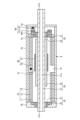
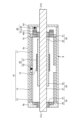
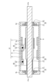
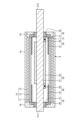
- FIG. 1 Side sectional view of the direct-acting rotary motor of Embodiment 1 Fig. 2 is a sectional side view when the output shaft of the linear motion rotary motor according to the first embodiment is linearly moved and rotated; Sectional view showing the linear motion rotary motor of Embodiment 1 Sectional view showing the linear motion rotary motor of Embodiment 1 Sectional view showing the linear motion rotary motor of Embodiment 2 Sectional view showing a linear motion rotary motor of Embodiment 3 Sectional view showing a linear motion rotary motor of Embodiment 4 FIG.
- FIG. 11 is a development view showing an example of a linear motion scale included in the linear motion rotary motor of the fourth embodiment; Side cross-sectional view of a direct-acting rotary motor according to Embodiment 5 Side sectional view of the linear motion rotary motor of Embodiment 6 Side cross-sectional view of a direct-acting rotary motor according to Embodiment 7 Side cross-sectional view of the linear motion rotary motor of the eighth embodiment Side cross-sectional view of the linear motion rotary motor of the ninth embodiment Side sectional view of a linear motion rotary motor according to the tenth embodiment Side sectional view of the linear motion rotary motor of the eleventh embodiment Side sectional view of a direct-acting rotary motor according to Embodiment 12 Side sectional view of a direct-acting rotary motor according to Embodiment 13 Side cross-sectional view of a direct-acting rotary motor according to the fourteenth embodiment Side sectional view of a direct-acting rotary motor according to the fifteenth embodiment
- FIG. 16 is a
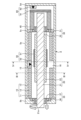
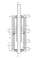
- FIG. 1 is a side cross-sectional view of a direct-acting rotary motor according to Embodiment 1.
- FIG. FIG. 2 is a side cross-sectional view when the output shaft of the linear motion rotary motor according to Embodiment 1 is linearly moved and rotated.
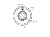
- FIG. 3 is a cross-sectional view showing the direct-acting rotary motor according to the first embodiment.
- FIG. 3 is a cross-sectional view taken along line III-III of FIG.
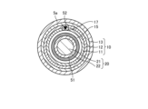
- FIG. 4 is a cross-sectional view showing the direct-acting rotary motor according to the first embodiment.
- FIG. 4 is a cross-sectional view taken along line IV-IV of FIG.
- the direct-acting rotary motor has a frame 5 which is a cylindrical housing.
- the frame 5 has a hollow cylindrical frame body 5a, a first end plate 5b, an intermediate plate 5c, and a second end plate 5d.
- a frame 5 incorporates a motor section and a position detection section.
- the motor section includes a stator 10 and a mover 20.
- the stator 10 includes a direct acting coil (propulsion coil) 11 , a rotating coil 12 and a stator core 13 .
- the mover 20 includes a shaft 21 and a magnet 22 that is a field magnet.
- the magnet 22 is arranged on the outer circumference of the shaft 21 .
- a shaft 21 of the mover 20 is supported by a pair of linear motion rotary bearings 30 and 35 so that it can move in the linear direction and rotate in the rotational direction. That is, the shaft 21 is supported by the frame 5 so as to be linearly and rotatably supported.
- the position detection section includes a linear position detection section 50 that detects the position of the movable element 20 in the linear direction, and a rotational position detection section 60 that detects the position of the movable element 20 in the rotational direction.
- the linear motion position detection unit 50 includes a linear motion scale 51 arranged on the mover 20 and a linear motion detector 52 that reads the linear motion scale 51 .
- the rotational position detection unit 60 includes a rotation scale 61 connected to the mover 20 and a rotation detector 62 that reads the rotation scale 61 .
- the linear motion direction of the mover 20 may be simply referred to as the linear motion direction.
- the direct acting coil 11 and the rotating coil 12 of the stator 10 are arranged concentrically as shown in FIG.
- a direct acting magnetic field is generated in the direct acting direction and a rotating magnetic field is generated in the rotating direction.
- the mover 20 moves in the translational direction and the rotational direction.
- a stator core 13 is arranged on the outer diameter side of the direct acting coil 11 and the rotating coil 12 .
- the magnetic flux of the magnet 22 can be effectively used, and the thrust and torque of the motor are improved.
- only the direct acting coil 11 and the rotating coil 12 may be arranged on the stator 10 without arranging the stator core 13 on the stator 10 .
- the direct-acting coil 11 By arranging the direct-acting coil 11 closer to the inner diameter side of the stator 10 than the rotating coil 12, leakage magnetic flux is reduced and the thrust of the motor is improved. If it is desired to improve the torque rather than the thrust force, the rotating coil 12 may be arranged closer to the inner diameter side of the stator 10 than the direct acting coil 11 .
- the implementation of configuring the stator 10 only with the direct-acting coils 11 and the rotating coils 12 without arranging the stator core 13 in the stator 10 may be applied to each embodiment described later. .
- the magnet 22 of the mover 20 generates electromagnetic force in both the linear motion direction and the rotational direction. For this reason, in the magnet 22, the north and south poles of the rhombic magnet are arranged alternately in the linear motion direction and in the rotational direction.
- rectangular N poles and S poles may be arranged alternately.
- a Halbach array may be employed in which magnets magnetized parallel to the surface of the mover 20 are arranged between the north and south poles of rhombic magnets.
- a magnet embedded type in which a magnet is embedded in an iron core may be used.
- the shaft 21 has an output shaft 21a exposed outside the first end plate 5b on one end side of the frame 5.
- a linear motion rotary bearing 35 as a first linear motion rotary bearing disposed on the first end plate 5 b on the output shaft 21 a side is composed of a bearing 36 and a ball spline 37 .
- a linear motion rotary bearing 30 as a second linear motion rotary bearing disposed on the intermediate plate 5c facing the first end plate 5b is composed of a bearing 31 and a ball spline 32 .
- the linear motion rotary bearings 30 and 35 may be a combination of a bearing and a slide bush, a stroke bush, a slide rotary bush, a linear rotary bush, a linear ball bush, or a slide bearing for cost reduction.
- a linear motion scale 51 that constitutes the linear motion position detection unit 50 is disposed in a gap 15 that is an air gap between the magnet 22 and the direct motion coil 11 that is the coil on the inner diameter side.
- the linear motion scale 51 is arranged on the outer circumference of the mover 20 in the gap 15 .
- the linear motion scale 51 is arranged on the outer peripheral surface of the magnet 22 in the gap 15 .
- the length of the linear motion scale 51 in the linear motion direction corresponds to the stroke length, which is the movable range of the mover 20 in the linear motion direction.
- the linear motion scale 51 is provided over the rotational range of the movable element 20 in the circumferential direction.
- the linear motion scale 51 is arranged over the entire circumference of the mover 20 .
- the linear motion detector 52 that constitutes the linear motion position detection unit 50 is arranged on the frame main body 5a of the frame 5 so as to face the magnet 22, as shown in FIGS. Further, the linear motion detector 52 is provided within the linear motion range of the linear motion scale 51 on the inner peripheral wall of the frame main body 5 a of the frame 5 . In Embodiment 1, the linear motion detector 52 is arranged in the middle of the arrangement position of the linear motion rotary bearings 30 and 35 in the direction of linear motion. As shown in FIGS. 1 and 4, the stator core 13 extending in the linear motion direction, the linear motion coil 11 and the rotation coil 12 extend in the entire circumferential direction at one central point in the linear motion direction. A space 16 is provided.
- a straight line is sandwiched between the stator core 13 and the stator core 13 , sandwiched between the linear motion coil 11 and the direct motion coil 11 , and sandwiched between the rotation coil 12 and the rotation coil 12 .
- a motion detector 52 is positioned. That is, the stator core 13, the direct acting coil 11, and the rotating coil 12 are separated in the direct acting direction, and the linear motion detection is performed between the separated stator core 13, the direct acting coil 11, and the rotating coil 12.
- a vessel 52 is arranged.
- the linear motion detector 52 may be arranged so as to be sandwiched only by the stator core 13. Alternatively, the linear motion detector 52 may be placed between the stator core 13 and the rotating coil, which is the coil on the outer diameter side.
- the linear motion detector 52 may be arranged so as to be sandwiched only by the rotating coil 12 which is the coil on the outer diameter side. Such various arrangements in the radial direction of the linear motion detector 52 may be applied to each embodiment described later in which the linear motion coil 11, the rotating coil 12, and the stator core 13 are concentrically arranged. good.
- the linear motion scale 51 is arranged on the surface of the magnet 22 on the outer diameter side, and is arranged in the linear motion direction so that the linear motion detector 52 always faces when the mover 20 translates or rotates. It is provided so as to cover the entire range of motion and the entire range of rotation in the circumferential direction. Therefore, the position in the linear motion direction can be detected over the entire stroke length range and over the entire circumferential range from 0 degrees to 360 degrees.
- the linear motion scale 51 is an optical scale in which scales extending in one direction are arranged on the entire sheet-like member, and is fixed to the surface of the magnet 22 of the mover 20 with an adhesive. By making the linear motion scale 51 optical, it is not affected by the magnetic fields of the magnet 22 and the linear motion coil 11 and the rotation coil 12 even if it is arranged in the gap 15 between the magnet 22 and the linear motion coil 11 .
- the direct-acting scale 51 may be adhered to the outer periphery of the magnet 22, or a cylindrical metal member may be arranged on the outer periphery of the magnet 22 and the scale may be formed directly on the metal member. Alternatively, a magnet may be embedded in a metal member having a scale formed thereon so that the metal member has both the function of the direct-acting scale 51 and the function of holding the magnet 22 .
- the rotation detector 62 that constitutes the rotation position detection unit 60 is fixed to the first end plate 5b on the side where the output shaft 21a is arranged and the second end plate 5d on the opposite side.
- a rotary scale 61 that constitutes the rotary position detector 60 is arranged on the shaft end side of the shaft 21 opposite to the output shaft 21a.
- the rotation scale 61 is engraved with graduations along the entire circumference in the direction of rotation.
- a rotation detector 62 reads the scale engraved on the rotation scale 61 .
- a rotary scale mounting portion 40 having a hollow structure and having a built-in ball spline 32 is provided in order to suppress the movement in the linear motion direction of the shaft end on the opposite side of the output shaft 21a.
- the rotary scale mounting portion 40 is fixed to the outer peripheral portion of the ball spline 32 .
- the rotary scale 61 is fixed to the rotary scale mounting portion 40 and rotates, but does not move in the linear motion direction.
- the rotary scale 61 is an optical scale.
- a magnetic detector and scale may be used as the rotation detector 62 and the rotation scale 61 for cost reduction.
- the linear motion scale 51 is provided on the surface of the magnet 22 so as to cover the entire movable range in the linear direction and the entire rotational range in the circumferential direction. Even when the element 20 moves in the direction of linear motion and rotates in the direction of rotation, the linear motion detector 52 and the linear motion scale 51 face each other at a constant interval, and the rotation detector 62 and the rotation scale 61 also face each other at a constant distance. facing each other at intervals.
- the linear motion scale 51 is arranged on the surface of the magnet 22 of the mover 20, the linear motion scale 51 is provided in the gap 15 between the stator 10 and the mover 20, Moreover, since the linear motion scale 51 is arranged so as to cover the entire movable range in the linear direction and the entire rotational range in the circumferential direction, there is no need for a structure for preventing the rotation of the mover, and the size and structure of the motor can be reduced. A simplification is realized.
- FIG. 5 is a cross-sectional view showing a direct-acting rotary motor according to the second embodiment.
- FIG. 5 corresponds to a cross-sectional view taken along line IV-IV in FIG.
- a cross section of the linear motion rotary motor of the second embodiment taken along line III-III in FIG. 1 is the same as the cross section shown in FIG.
- the second embodiment differs from the first embodiment in the arrangement of the linear motion detector 52 .
- Other configurations of the second embodiment are the same as those of the first embodiment, and overlapping descriptions are omitted.
- a space 16 extending over the entire circumferential direction is provided at one point in the middle of the stator core 13, the direct acting coil 11 and the rotating coil 12 in the direct acting direction.
- a concave portion 17 capable of accommodating a linear motion detector 52 is provided at one central location in the linear motion direction of the linear motion coil 11 and the rotation coil 12, and the linear motion detector 52 is placed in the concave portion 17. inserting.
- Linear motion detector 52 is arranged on the inner peripheral surface of stator core 13 .
- the concave portion 17 may be formed to extend to the stator core 13 and the linear motion detector 52 may be arranged on the inner peripheral wall of the frame body 5a of the frame 5 .
- the motor loss is reduced by increasing the volume of the direct acting coil 11 and the rotating coil 12, and the direct acting coil 11, the rotating coil 12, and the direct acting detector
- the cost can be reduced by integrally manufacturing 52.
- one of the direct acting coil 11 and the rotating coil 12, or both the direct acting coil 11 and the rotating coil 12 may be formed of a printed board or a flexible board, and the direct acting detector 52 may be mounted on these boards. good.
- FIG. 6 is a cross-sectional view showing a direct-acting rotary motor according to Embodiment 3.
- FIG. FIG. 6 corresponds to a cross-sectional view taken along line IV-IV in FIG.
- a cross section of the linear motion rotary motor of Embodiment 3 taken along line III-III in FIG. 1 is the same as the cross section shown in FIG.
- the third embodiment differs from the first embodiment in the arrangement of the linear motion detector 52 .
- Other configurations of the third embodiment are the same as those of the first embodiment, and overlapping descriptions are omitted.
- a direct motion detector 52 is arranged on the surface of the direct motion coil 11, which is the coil on the inner diameter side.
- the linear motion detector 52 may be adhered to the surface of the direct motion coil 11, or the direct motion coil 11 may be formed of a printed circuit board or a flexible substrate, and the linear motion detector 52 may be mounted on the surface of these substrates. . It should be noted that the practice of arranging the linear motion detector 52 on the surface of the coil on the inner diameter side may be applied to each embodiment described later.
- the distance between the linear motion detector 52 and the linear motion scale 51 can be reduced, so that the positional accuracy is improved.
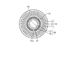
- FIG. 7 is a cross-sectional view showing a direct-acting rotary motor according to Embodiment 4.
- FIG. FIG. 7 corresponds to a cross-sectional view along line III-III in FIG.
- FIG. 8 is a developed view showing an example of the linear motion scale 51 included in the linear motion rotary motor of the fourth embodiment.
- a cross section of the linear motion rotary motor of Embodiment 4 taken along line IV-IV in FIG. 1 is the same as the cross section shown in any one of FIGS.
- the fourth embodiment differs from the first embodiment in the arrangement of the linear scale 51 .
- Other configurations of the fourth embodiment are the same as those of any one of the first to third embodiments, and overlapping descriptions are omitted.
- a sheet-like member is fixed to the surface of the magnet 22 of the mover 20 with an adhesive. It becomes an undetectable area in For this reason, in the fourth embodiment, the rotational range of the mover 20 in the circumferential direction is limited so that the linear motion detector 52 and the joint portion 51a do not face each other.
- the linear motion scale 51 is an optical scale in which scales in one direction are continuously formed at intervals over the entire sheet-like member.
- the linear motion scale 51 shown in FIG. 8 also exemplifies the linear motion scale 51 included in the linear motion rotary motors of the embodiments other than the fourth embodiment.
- the linear scale 51 it is not necessary to arrange the linear scale 51 over the entire circumference of the mover 20, and in addition to the effects of the first embodiment, the cost of the linear scale 51 can be reduced.
- FIG. 9 is a side cross-sectional view of a direct-acting rotary motor according to Embodiment 5.
- the rotating scale 61a has a doughnut-shaped hollow structure. Further, the axial length of the shaft 21 of the rotary scale mounting portion 40a is made shorter than that of the rotary scale mounting portion 40 of FIG. Further, a hole is formed in the second end plate 5d of the frame 5 to expose the shaft portion 21b of the shaft 21 on the opposite side of the output shaft 21a, and the shaft portion 21b of the shaft 21 extends outwardly from the second end plate 5d of the frame 5. exposed to Other configurations of the fifth embodiment are the same as those of the first embodiment, and overlapping descriptions are omitted.
- the rotary scale 61a has a hollow structure, the shaft 21 of the mover 20 and the rotary scale 61a do not interfere with each other. 21b can be exposed from the frame 5; Therefore, in addition to the effects of the first embodiment, the effect that the size of the rotational position detection unit 60 in the linear motion direction can be reduced by the stroke length of the mover 20 is obtained.
- FIG. 10 is a side sectional view of a direct-acting rotary motor according to Embodiment 6.
- the shaft 21 has a hollow structure and a through hole 21c is provided.
- Other configurations of the sixth embodiment are the same as those of the fifth embodiment, and overlapping descriptions are omitted.
- the pressure inside the shaft 21 can be reduced by connecting a vacuum ejector to the through hole 21c in the shaft portion opposite to the output shaft 21a.
- the shaft 21 since the shaft 21 has a hollow structure, the inside of the shaft 21 can be decompressed without using a separate tube.
- the effect of facilitating assembly and maintenance of the device is obtained.
- the configuration in which the shaft 21 has a hollow structure and the through hole 21c is provided may be applied to any one of the first to fourth embodiments and the seventh to fifteenth embodiments.
- FIG. 11 is a side sectional view of a direct-acting rotary motor according to Embodiment 7.
- the direct acting coil 11 and the rotating coil 12 are separated in the direct acting direction, and the direct acting detector 52 is arranged between the direct acting coil 11 and the rotating coil 12 .
- the linear motion detector 52 is fixed to the inner peripheral wall of the frame body 5 a of the frame 5 .
- Other configurations of the seventh embodiment are the same as those of the fifth embodiment, and overlapping descriptions are omitted.
- the total length of the direct-acting coil 11 and the rotating coil 12 is greater than the length of the magnet 22 in the direct-acting direction. Therefore, the area where the linear motion coil 11 and the magnet 22 face each other and the area where the rotation coil 12 and the magnet 22 face each other change depending on the position of the mover 20 in the linear motion direction.
- Embodiment 7 since the direct acting coil 11 and the rotating coil 12 are arranged separately in the direct acting direction, it is possible to reduce the size of the motor in the radial direction. Also, depending on the position of the mover 20 in the linear motion direction, the area where the linear motion coil 11 and the magnet 22 face each other and the area where the rotation coil 12 and the magnet 22 face each other, that is, the thrust constant and the torque constant vary. Therefore, motor loss can be reduced by generating a current command according to the position of the mover 20 in the linear motion direction.
- FIG. 12 is a side sectional view of a direct-acting rotary motor according to Embodiment 8.
- the direct acting coil 11 and the rotating coil 12 are separated in the direct acting direction, and the direct acting detector 52 is arranged between the direct acting coil 11 and the rotating coil 12 .
- the total length of the direct acting coil 11 and the rotating coil 12 is smaller than the length of the magnet 22 in the direct acting direction. Therefore, the area where direct acting coil 11 and magnet 22 face each other and the area where rotating coil 12 and magnet 22 face each other do not change depending on the position of mover 20 .
- the direct-acting rotary bearing 30 composed of the bearing 31 and the ball spline 32 is provided on the second end plate 5d instead of the intermediate plate 5c.
- the rotary scale mounting portion 40a is provided on the outer circumference of the ball spline 32, and rotates according to the rotation of the mover 20, but does not move in the linear motion direction even if the mover 20 moves linearly.
- the rotary scale 61a is fixed to the rotary scale mounting portion 40a. Therefore, the rotary scale 61a also rotates according to the rotation of the mover 20, but does not move in the linear motion direction even if the mover 20 moves linearly.
- a hole 5c1 is formed in the intermediate plate 5c for linear movement and rotation of the mover 20.
- the rotation detector 62 is fixed to the intermediate plate 5c and reads the scale of a rotation scale 61a provided at a constant distance.
- the rotation detector 62 is arranged so as to line up with a part of the magnet 22 of the mover 20 in the radial direction of the motor. Therefore, the total length of the direct-acting rotary motor in the direct-acting direction can be reduced.
- Other configurations of the eighth embodiment are the same as those of the seventh embodiment, and overlapping descriptions are omitted.
- the direct acting coil 11 and the rotating coil 12 are arranged separately in the direct acting direction, it is possible to reduce the size of the motor in the radial direction. Further, the area where direct acting coil 11 and magnet 22 face each other and the area where rotating coil 12 and magnet 22 face each other do not change depending on the position of mover 20 . Therefore, it is not necessary to generate a current command in accordance with the position of the mover 20 in the linear motion direction, and control can be simplified. Furthermore, since the rotation detector 62 and the magnet 22 are arranged side by side in the radial direction of the motor, the overall length of the direct-acting rotary motor can be reduced.
- Embodiment 9. 13 is a side cross-sectional view of a direct-acting rotary motor according to Embodiment 9.
- FIG. 10 the rotational position detection unit 60 is arranged laterally in the axial direction of the motor unit composed of the stator 10 and the magnet 22 of the mover 20. Instead of arranging it in space, the rotational position detection section 60 is arranged in the space inside the motor section like the linear motion position detection section 50 .
- Other configurations of the ninth embodiment are the same as those of the first embodiment, and overlapping descriptions are omitted.
- the linear motion scale 51 and the rotary scale 61 are arranged at different axial positions on the surface of the magnet 22 in the gap 15 on the outer diameter side.
- the lengths of the linear motion scale 51 and the rotary scale 61 in the linear motion direction correspond to the stroke length, which is the movable range of the mover 20 in the linear motion direction.
- the linear scale 51 and the rotary scale 61 are provided so as to cover the entire movable range in the linear direction and the entire rotational range in the circumferential direction.
- the linear scale 51 and the rotary scale 61 are arranged adjacent to each other so that the increment directions of the scales are orthogonal to each other.
- the linear motion detector 52 is arranged in a space 16 formed so as to face the linear motion scale 51 at one point in the linear motion direction of the stator 10, and the frame of the frame 5. It is fixed to the inner peripheral wall of the main body 5a.
- the linear motion detector 52 is sandwiched between the stator core 13 and the stator core 13 , sandwiched between the linear motion coils 11 and 11 , and sandwiched between the rotation coils 12 and 12 . are arranged in the space 16 at .
- the rotation detector 62 is also the same, and is arranged in a space 19 formed so as to face the rotation scale 61 at one point in the linear motion direction of the stator core 13, the linear motion coil 11, and the rotation coil 12, It is fixed to the inner peripheral wall of the frame main body 5 a of the frame 5 .
- the rotation detector 62 is sandwiched between the stator core 13 and the stator core 13, sandwiched between the linear motion coils 11 and 11, and sandwiched between the rotation coils 12 and 12. It is arranged in space 19 .
- the linear motion detector 52 and the rotation detector 62 may be arranged so as to be sandwiched only by the stator core 13. It may be arranged so as to be sandwiched only between the coils for rotation 12, which are coils. Also, if the stator core 13 does not exist, the linear motion detector 52 and the rotation detector 62 may be arranged so as to be sandwiched only by the rotation coil 12, which is the coil on the outer diameter side. Further, as shown in FIG. 6, the linear motion detector 52 and the rotation detector 62 may be arranged on the surface of the inner coil of the linear motion coil 11 and the rotation coil 12 .
- the ninth embodiment it is possible to make the configuration of the linear motion position detection section 50 and the rotation position detection section 60 the same, and the cost of the position detector can be reduced by common parts. Furthermore, since the motor section and the position detection section are integrated, the total length of the motor can be shortened.
- FIG. 14 is a side cross-sectional view of a direct-acting rotary motor according to the tenth embodiment.
- the rotational position detection section 60 and the linear motion position detection section 50 are arranged in the space inside the motor section. Further, as in the seventh and eighth embodiments, the direct acting coil 11 and the rotating coil 12 are separated in the direct acting direction.
- a linear motion detector 52 is arranged between the linear motion coil 11 and the rotation coil 12 .
- the rotation detector 62 is arranged adjacent to the linear motion coil 11 .
- the linear motion detector 52 and the rotation detector 62 are fixed to the inner peripheral wall of the frame main body 5 a of the frame 5 .
- the linear scale 51 and the rotary scale 61 are arranged at different axial positions on the surface of the magnet 22 in the gap 15 on the outer diameter side.
- the linear motion scale 51 is arranged to face the linear motion detector 52
- the rotary scale 61 is arranged to face the rotation detector 62 .
- the linear scale 51 and the rotary scale 61 are provided so as to cover the entire movable range in the linear direction and the entire rotational range in the circumferential direction.
- the linear scale 51 and the rotary scale 61 are arranged adjacent to each other so that the increment directions of the scales are orthogonal to each other.
- the total length of the direct-acting coil 11 and the rotating coil 12 is smaller than the length of the magnet 22 in the direct-acting direction. Therefore, the area where the direct acting coil 11 and the magnet 22 face each other and the area where the rotating coil 12 and the magnet 22 face each other do not change depending on the position of the mover 20 in the direct motion direction.
- the direct acting coil 11 and the rotating coil 12 are arranged separately in the direct acting direction, it is possible to reduce the size of the motor in the radial direction. Moreover, since the motor section and the position detection section are integrated, the total length of the motor can be shortened. Further, the area where the linear motion coil 11 and the magnet 22 face each other and the area where the rotation coil 12 and the magnet 22 face each other do not change depending on the position of the mover 20 in the direction of linear motion. Therefore, it is not necessary to generate a current command in accordance with the position of the mover 20 in the linear motion direction, and control can be simplified. Note that the linear motion detector 52 and the rotation detector 62 may be arranged on either surface of the linear motion coil 11 or the rotation coil 12 .
- FIG. 15 is a side sectional view of a direct-acting rotary motor according to the eleventh embodiment.
- one of the linear position detector 50 and the rotational position detector 60 is arranged between the magnet 22 and the frame main body 5a of the frame 5, and the other is arranged at a portion of the shaft 21 where the magnet 22 does not exist. and the frame main body 5a of the frame 5.
- the linear position detector 50 is arranged between the magnet 22 and the frame main body 5a of the frame 5
- the rotational position detector 60 is arranged between the portion of the shaft 21 where the magnet 22 does not exist and the frame main body 5a of the frame 5.
- FIG. is placed between The rest of the configuration of the eleventh embodiment is the same as that of the tenth embodiment, and redundant description will be omitted.
- a rotation scale 61 of the rotation position detection unit 60 is arranged on the outer circumference of the shaft 21 at a location where the magnet 22 does not exist, and the rotation detector 62 is arranged on the inner peripheral wall of the frame main body 5a so as to face the rotation scale 61.
- the linear scale 51 and the rotary scale 61 are provided so as to cover the entire movable range in the linear direction and the entire rotational range in the circumferential direction.
- the linear motion scale 51 and the rotary scale 61 can be arranged on the shaft 21 . , there is an effect that the cost of the position detector can be reduced by common parts.
- FIG. 16 is a side sectional view of a direct-acting rotary motor according to the twelfth embodiment.
- the direct-acting coil 11 and the rotating coil 12 are separated in the direct-acting direction with the intermediate plate 5c interposed therebetween.
- the magnets of the mover 20 are separated in the linear motion direction into a linear motion magnet 22a and a rotation magnet 22b.
- the rotating magnet 22b is arranged in a space surrounded by the intermediate plates 5c and 5e.
- the linear motion detector 52 is arranged between the linear motion coils 11 and fixed to the inner peripheral wall of the frame main body 5a.
- a linear motion scale 51 is arranged on the outer circumference of the magnet 22 of the mover 20 in the gap 15 .
- the frame 5 has a frame body 5a, a first end plate 5b, an intermediate plate 5c, an intermediate plate 5e, and a second end plate 5d.
- a bearing 38 connected to the outer periphery of the ball spline 32 is provided on the intermediate plate 5e.
- the intermediate plate 5c is provided with a linear motion rotary bearing 30 composed of a bearing 31 and a ball spline 32. As shown in FIG.
- the linear motion rotary bearing 30 supports the base end portion 21 d of the shaft 21 .
- the rotating magnet 22b is arranged on the outer periphery of the ball spline 32. Since movement in the linear motion direction is suppressed by the ball spline 32 , the rotating magnet 22 b always faces the rotating coil 12 .
- the rotary scale 61 is fixed to a rotary scale mounting portion 40 arranged on the outer circumference of the ball spline 32 and rotates together with the ball spline 32 .
- the rotation detector 62 is fixed to the second end plate 5 d of the frame 5 with a certain distance from the rotation scale 61 .
- the magnet 22 for a direct-acting rotary motor is not required, and the direct-acting magnet 22a for a general direct-acting motor (shaft linear motor) and the rotating magnet 22b for a rotary motor can be used. , cost can be reduced by standardizing parts.
- the ball spline 32 is arranged on the inner diameter side of the rotating magnet 22b, it is possible to suppress the movement in the linear motion direction in the rotary motor portion, and the overall length of the motor can be reduced.
- FIG. 17 is a side sectional view of a direct-acting rotary motor according to the thirteenth embodiment.
- the stator 10 has a direct acting coil 11, a rotating coil 12, and a stator iron core 13, as in the first embodiment. placed on the perimeter wall.
- the linear motion detector 52 is arranged between the linear motion coil 11 and the rotation coil 12 , and the linear motion scale 51 is arranged on the outer circumference of the magnet 22 .
- the linear motion scale 51 is provided so as to cover the entire movable range in the linear motion direction and the entire rotational range in the circumferential direction.
- the rotation detector 62 is provided on the outer circumference of the shaft 21 of the mover 20 or the magnet 22 .
- the rotation detector 62 is provided on the outer circumference of the shaft 21 . Therefore, the rotation detector 62 moves in the linear motion direction and the rotation direction.
- the rotation scale 61 is arranged on the inner periphery of the linear motion coil 11, which is the coil on the inner diameter side, so as to face the rotation detector 62. As shown in FIG.
- the rotation scale 61 is provided over a linear movable range and a circumferential rotation range so as to face each other when the rotation detector 62 is linearly moved or rotated. Power supply and signal transmission to the rotation detector 62 may be performed wirelessly, or a slip ring may be used. Alternatively, the rotation range may be limited and wired. It should be noted that the arrangement of the linear position detector 50 and the rotational position detector 60 may be reversed.
- the total length of the motor can be shortened. Further, the configuration of the linear motion position detector 50 and the rotational position detector 60 can be made the same, and the cost of the position detector can be reduced by common parts.
- FIG. 18 is a side sectional view of a direct-acting rotary motor according to a fourteenth embodiment.
- the arrangement position of the linear motion position detector 50 of the thirteenth embodiment is changed.
- the rest of the configuration of the fourteenth embodiment is the same as that of the thirteenth embodiment, and redundant description will be omitted.
- the linear motion detector 52 and the rotation detector 62 are provided on the outer circumference of the shaft 21 of the mover 20 or the magnet 22 .
- the linear motion detector 52 and the rotation detector 62 are provided on the outer circumference of the shaft 21 .
- the linear motion scale 51 is arranged on the inner circumference of the linear motion coil 11 , which is the coil on the inner diameter side, so as to face the linear motion detector 52 .
- the rotation scale 61 is arranged on the inner periphery of the linear motion coil 11, which is the coil on the inner diameter side, so as to face the rotation detector 62. As shown in FIG.
- the linear motion scale 51 and the rotation scale 61 are provided over a linear movable range and a circumferential rotation range so as to face each other when the linear motion detector 52 and the rotation detector 62 are linearly moved or rotated.
- Embodiment 14 since the motor section and the position detection section are integrated, the total length of the motor can be shortened. Further, the configuration of the linear motion position detector 50 and the rotational position detector 60 can be made the same, and the cost of the position detector can be reduced by common parts. Furthermore, motor loss can be reduced by increasing the volume of the direct acting coil 11 and the rotating coil 12 .
- FIG. 19 is a side sectional view of a direct-acting rotary motor according to a fifteenth embodiment.
- a linear motion rotary scale 80 having functions of a linear motion scale and a rotary scale is employed.
- the linear motion rotary scale 80 is obtained by integrating a linear motion scale and a rotary scale into the same part.
- the linear motion detector 52 and the rotation detector 62 are arranged at the same position in the linear motion direction on the inner peripheral wall of the frame main body 5a with the mover 20 as the center so as to face the linear motion rotation scale 80. .
- the stator 10 has a direct acting coil 11, a rotating coil 12, and a stator iron core 13, which are concentrically arranged on the inner peripheral wall of the frame body 5a of the frame 5, as in the first embodiment.
- the linear motion detector 52 is arranged between the linear motion coil 11 and the rotation coil 12 and fixed to the stator core 13 .
- Rotation detector 62 is arranged between direct-acting coil 11 and rotating coil 12 , is arranged at a position different in the circumferential direction from direct-acting detector 52 , and is fixed to stator core 13 .
- the rotation detector 62 may be arranged to face the linear motion detector 52 with the mover 20 interposed therebetween.
- the linear motion detector 52 and the rotation detector 62 may be integrated and arranged at different positions on one substrate.
- the linear motion rotary scale 80 is arranged on the outer circumference of the mover 20 in the gap 15 . Specifically, the linear motion rotary scale 80 is arranged on the outer circumference of the magnet 22 .
- the linear motion rotary scale 80 is provided over a linear movable range and a circumferential rotational range so that the linear motion detector 52 and the rotation detector 62 face each other when the mover 20 translates or rotates.
- the direct-acting rotary scale 80 is an optical scale in which two-direction scales that intersect perpendicularly are formed on the entire sheet-shaped member, and is fixed to the surface of the magnet 22 with an adhesive.
- a cylindrical metal member may be arranged on the outer circumference of the magnet 22 to form the scale directly on the metal, or the magnet may be embedded in the metal member with the scale formed thereon so that the metal member can hold both the scale and the magnet. may have the function of
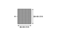
- FIG. 20 is a developed view showing an example of the linear motion rotary scale 80 provided in the linear motion rotary motor of the fifteenth embodiment.
- the linear motion rotary scale 80 of FIG. 20 has graduations formed in two directions perpendicular to the entire scale, and the linear motion detector 52 and the rotation detector 62 are used to detect both the linear motion direction and the rotation direction over the entire scale. displacement can be detected.
- FIG. 21 is a developed view showing another example of the linear motion rotary scale 80 provided in the linear motion rotary motor of the fifteenth embodiment.
- the linear rotary scale 80 of FIG. 21 is a combination of two unidirectionally graduated scales, one unidirectionally graduated and the other orthogonally graduated. ing. Although the movable range of the motor in the circumferential direction is 180 degrees or less, the cost of the scale can be reduced because a scale forming a unidirectional scale can be used.
- the scale can be made smaller, and the mover 20 is small in the linear motion direction, a scale for detecting the position in the linear motion direction can be arranged on the mover 20 .
- the linear motion detector 52 and the rotation detector 62 may be arranged on the surface of the inner coil of the linear motion coil 11 and the rotation coil 12 .
- the configuration shown in the above embodiment shows an example of the content of the present disclosure, and can be combined with another known technology. It is also possible to omit or change the part.
Landscapes
- Engineering & Computer Science (AREA)
- Power Engineering (AREA)
- Microelectronics & Electronic Packaging (AREA)
- General Engineering & Computer Science (AREA)
- Physics & Mathematics (AREA)
- Chemical & Material Sciences (AREA)
- Combustion & Propulsion (AREA)
- Electromagnetism (AREA)
- Mechanical Engineering (AREA)
- Linear Motors (AREA)
Priority Applications (6)
| Application Number | Priority Date | Filing Date | Title |
|---|---|---|---|
| US18/709,519 US20250007377A1 (en) | 2021-11-26 | 2021-11-26 | Linear rotary motor |
| KR1020247015267A KR102845194B1 (ko) | 2021-11-26 | 2021-11-26 | 직동 회전 모터 |
| JP2022564832A JP7237256B1 (ja) | 2021-11-26 | 2021-11-26 | 直動回転モータ |
| PCT/JP2021/043399 WO2023095285A1 (ja) | 2021-11-26 | 2021-11-26 | 直動回転モータ |
| CN202180103373.XA CN118216077A (zh) | 2021-11-26 | 2021-11-26 | 直动旋转电动机 |
| DE112021008477.1T DE112021008477T5 (de) | 2021-11-26 | 2021-11-26 | Lineardrehmotor |
Applications Claiming Priority (1)
| Application Number | Priority Date | Filing Date | Title |
|---|---|---|---|
| PCT/JP2021/043399 WO2023095285A1 (ja) | 2021-11-26 | 2021-11-26 | 直動回転モータ |
Publications (1)
| Publication Number | Publication Date |
|---|---|
| WO2023095285A1 true WO2023095285A1 (ja) | 2023-06-01 |
Family
ID=85503258
Family Applications (1)
| Application Number | Title | Priority Date | Filing Date |
|---|---|---|---|
| PCT/JP2021/043399 Ceased WO2023095285A1 (ja) | 2021-11-26 | 2021-11-26 | 直動回転モータ |
Country Status (6)
| Country | Link |
|---|---|
| US (1) | US20250007377A1 (https=) |
| JP (1) | JP7237256B1 (https=) |
| KR (1) | KR102845194B1 (https=) |
| CN (1) | CN118216077A (https=) |
| DE (1) | DE112021008477T5 (https=) |
| WO (1) | WO2023095285A1 (https=) |
Cited By (3)
| Publication number | Priority date | Publication date | Assignee | Title |
|---|---|---|---|---|
| JP7570586B1 (ja) * | 2023-09-15 | 2024-10-21 | 三菱電機株式会社 | 多軸アクチュエータ用コイルおよび多軸アクチュエータ |
| JP7570587B1 (ja) * | 2023-09-15 | 2024-10-21 | 三菱電機株式会社 | 多軸アクチュエータ |
| JP7766850B1 (ja) * | 2024-10-09 | 2025-11-10 | 三菱電機株式会社 | 直動回転アクチュエータに用いられる永久磁石 |
Families Citing this family (2)
| Publication number | Priority date | Publication date | Assignee | Title |
|---|---|---|---|---|
| JP7662788B2 (ja) * | 2022-11-29 | 2025-04-15 | エーエーシー テクノロジーズ (ナンジン) カンパニーリミテッド | マルチ可動子ダイレクトドライブトランスミッションシステム |
| EP4528119B1 (en) * | 2023-09-25 | 2026-02-25 | Physik Instrumente (PI) SE & Co. KG | Electromagnetic actuator |
Citations (3)
| Publication number | Priority date | Publication date | Assignee | Title |
|---|---|---|---|---|
| US20070176497A1 (en) * | 1996-06-24 | 2007-08-02 | Anorad Corporation | System and method to control a rotary-linear actuator |
| JP2011147333A (ja) * | 2010-01-15 | 2011-07-28 | Maxon Motor Ag | リニアドライブ |
| JP2012016180A (ja) * | 2010-07-01 | 2012-01-19 | Yaskawa Electric Corp | アクチュエータ |
Family Cites Families (1)
| Publication number | Priority date | Publication date | Assignee | Title |
|---|---|---|---|---|
| EP2403118A3 (en) * | 2010-07-01 | 2014-10-29 | Kabushiki Kaisha Yaskawa Denki | Actuator |
-
2021
- 2021-11-26 US US18/709,519 patent/US20250007377A1/en active Pending
- 2021-11-26 WO PCT/JP2021/043399 patent/WO2023095285A1/ja not_active Ceased
- 2021-11-26 KR KR1020247015267A patent/KR102845194B1/ko active Active
- 2021-11-26 DE DE112021008477.1T patent/DE112021008477T5/de active Pending
- 2021-11-26 CN CN202180103373.XA patent/CN118216077A/zh active Pending
- 2021-11-26 JP JP2022564832A patent/JP7237256B1/ja active Active
Patent Citations (3)
| Publication number | Priority date | Publication date | Assignee | Title |
|---|---|---|---|---|
| US20070176497A1 (en) * | 1996-06-24 | 2007-08-02 | Anorad Corporation | System and method to control a rotary-linear actuator |
| JP2011147333A (ja) * | 2010-01-15 | 2011-07-28 | Maxon Motor Ag | リニアドライブ |
| JP2012016180A (ja) * | 2010-07-01 | 2012-01-19 | Yaskawa Electric Corp | アクチュエータ |
Cited By (6)
| Publication number | Priority date | Publication date | Assignee | Title |
|---|---|---|---|---|
| JP7570586B1 (ja) * | 2023-09-15 | 2024-10-21 | 三菱電機株式会社 | 多軸アクチュエータ用コイルおよび多軸アクチュエータ |
| JP7570587B1 (ja) * | 2023-09-15 | 2024-10-21 | 三菱電機株式会社 | 多軸アクチュエータ |
| WO2025057408A1 (ja) * | 2023-09-15 | 2025-03-20 | 三菱電機株式会社 | 多軸アクチュエータ |
| WO2025057407A1 (ja) * | 2023-09-15 | 2025-03-20 | 三菱電機株式会社 | 多軸アクチュエータ用コイルおよび多軸アクチュエータ |
| JP7766850B1 (ja) * | 2024-10-09 | 2025-11-10 | 三菱電機株式会社 | 直動回転アクチュエータに用いられる永久磁石 |
| WO2026078806A1 (ja) * | 2024-10-09 | 2026-04-16 | 三菱電機株式会社 | 直動回転アクチュエータに用いられる永久磁石 |
Also Published As
| Publication number | Publication date |
|---|---|
| KR102845194B1 (ko) | 2025-08-11 |
| KR20240090356A (ko) | 2024-06-21 |
| CN118216077A (zh) | 2024-06-18 |
| US20250007377A1 (en) | 2025-01-02 |
| DE112021008477T5 (de) | 2024-09-12 |
| JPWO2023095285A1 (https=) | 2023-06-01 |
| JP7237256B1 (ja) | 2023-03-10 |
Similar Documents
| Publication | Publication Date | Title |
|---|---|---|
| JP7237256B1 (ja) | 直動回転モータ | |
| EP2209186B1 (en) | Magnetically-levitated motor and pump | |
| KR101475555B1 (ko) | 액추에이터 | |
| KR100680152B1 (ko) | 감속기 일체형 액츄에이터 | |
| JP4169536B2 (ja) | アクチュエータ | |
| CN115917935A (zh) | 旋转驱动装置以及泵 | |
| JP2006233985A (ja) | 回転検出装置付き軸受 | |
| EP2587223A2 (en) | Magnetic encoder with improved resolution | |
| US20090123098A1 (en) | Bearing With Rotation Detection Device | |
| JP2017215302A (ja) | 直動回転検出器、直動回転検出器ユニットおよび直動回転駆動装置 | |
| CN117240138B (zh) | 传感与控制一体化的磁悬浮装置及磁悬浮设备 | |
| JP2009271054A (ja) | 位置検出装置およびそれを備えた回転直動モータ | |
| CN107792397B (zh) | 一种完全非接触的双框架磁悬浮控制力矩陀螺 | |
| JP2002310609A (ja) | 回転角度検出装置 | |
| JP4918406B2 (ja) | 電磁クラッチ | |
| JP2012016180A (ja) | アクチュエータ | |
| JP3511790B2 (ja) | ブラシレスモータ | |
| CN108282069B (zh) | 超低速单元式拼接盘式磁悬浮力矩电机 | |
| CN224006579U (zh) | 电动致动器 | |
| US20250364867A1 (en) | Electric motor | |
| JP2529328Y2 (ja) | 回転センサ付永久磁石形ステッピングモータ | |
| JP5206749B2 (ja) | アクチュエータ | |
| JPH0511944Y2 (https=) | ||
| JP2002022572A (ja) | 動力計 | |
| JPS63213457A (ja) | ダイレクト・ドライブ・モ−タ |
Legal Events
| Date | Code | Title | Description |
|---|---|---|---|
| WWE | Wipo information: entry into national phase |
Ref document number: 2022564832 Country of ref document: JP |
|
| 121 | Ep: the epo has been informed by wipo that ep was designated in this application |
Ref document number: 21965656 Country of ref document: EP Kind code of ref document: A1 |
|
| WWE | Wipo information: entry into national phase |
Ref document number: 202180103373.X Country of ref document: CN |
|
| ENP | Entry into the national phase |
Ref document number: 20247015267 Country of ref document: KR Kind code of ref document: A |
|
| WWE | Wipo information: entry into national phase |
Ref document number: 18709519 Country of ref document: US |
|
| 122 | Ep: pct application non-entry in european phase |
Ref document number: 21965656 Country of ref document: EP Kind code of ref document: A1 |