WO2023089989A1 - 撮像装置 - Google Patents
撮像装置 Download PDFInfo
- Publication number
- WO2023089989A1 WO2023089989A1 PCT/JP2022/037964 JP2022037964W WO2023089989A1 WO 2023089989 A1 WO2023089989 A1 WO 2023089989A1 JP 2022037964 W JP2022037964 W JP 2022037964W WO 2023089989 A1 WO2023089989 A1 WO 2023089989A1
- Authority
- WO
- WIPO (PCT)
- Prior art keywords
- cover
- imaging device
- substrate
- damping member
- housing
- Prior art date
- Legal status (The legal status is an assumption and is not a legal conclusion. Google has not performed a legal analysis and makes no representation as to the accuracy of the status listed.)
- Ceased
Links
Images






Classifications
-
- G—PHYSICS
- G03—PHOTOGRAPHY; CINEMATOGRAPHY; ANALOGOUS TECHNIQUES USING WAVES OTHER THAN OPTICAL WAVES; ELECTROGRAPHY; HOLOGRAPHY
- G03B—APPARATUS OR ARRANGEMENTS FOR TAKING PHOTOGRAPHS OR FOR PROJECTING OR VIEWING THEM; APPARATUS OR ARRANGEMENTS EMPLOYING ANALOGOUS TECHNIQUES USING WAVES OTHER THAN OPTICAL WAVES; ACCESSORIES THEREFOR
- G03B15/00—Special procedures for taking photographs; Apparatus therefor
-
- G—PHYSICS
- G03—PHOTOGRAPHY; CINEMATOGRAPHY; ANALOGOUS TECHNIQUES USING WAVES OTHER THAN OPTICAL WAVES; ELECTROGRAPHY; HOLOGRAPHY
- G03B—APPARATUS OR ARRANGEMENTS FOR TAKING PHOTOGRAPHS OR FOR PROJECTING OR VIEWING THEM; APPARATUS OR ARRANGEMENTS EMPLOYING ANALOGOUS TECHNIQUES USING WAVES OTHER THAN OPTICAL WAVES; ACCESSORIES THEREFOR
- G03B17/00—Details of cameras or camera bodies; Accessories therefor
- G03B17/02—Bodies
-
- G—PHYSICS
- G03—PHOTOGRAPHY; CINEMATOGRAPHY; ANALOGOUS TECHNIQUES USING WAVES OTHER THAN OPTICAL WAVES; ELECTROGRAPHY; HOLOGRAPHY
- G03B—APPARATUS OR ARRANGEMENTS FOR TAKING PHOTOGRAPHS OR FOR PROJECTING OR VIEWING THEM; APPARATUS OR ARRANGEMENTS EMPLOYING ANALOGOUS TECHNIQUES USING WAVES OTHER THAN OPTICAL WAVES; ACCESSORIES THEREFOR
- G03B35/00—Stereoscopic photography
- G03B35/08—Stereoscopic photography by simultaneous recording
Definitions
- the present invention relates to an imaging device that is mounted on a vehicle and captures an image of the front of the vehicle.
- driver assistance systems In recent years, with the aim of realizing a safe and comfortable car society, the installation of driver assistance systems in actual vehicles is progressing. Among them are a collision damage mitigation braking system that automatically decelerates before colliding with an obstacle, an automatic distance control system that automatically tracks the vehicle while maintaining a substantially constant distance from the preceding vehicle, and a lane departure control system. , and sign recognition systems, etc., are being developed in pursuit of safety, convenience, and comfort for drivers and passengers. Realization of such a driver support system requires an external world recognition system that recognizes vehicles, pedestrians, road surfaces, etc., and measures the distance to objects.
- FIG. 1A is an external perspective view of a conventional imaging device from above
- FIG. 1B is an external perspective view of the conventional imaging device from below.
- This imaging device is attached to the vehicle so that the positive direction of the x-axis of the imaging device coincides with the traveling direction of the vehicle, the positive direction of the y-axis coincides with the upward direction of the vehicle, and the positive direction of the z-axis coincides with the rightward direction of the vehicle.
- This imaging device includes a metal (for example, aluminum die-cast) housing 1 having fins on the top surface and a space inside, and a metal (for example, It has a cover 10 made of an aluminum plate) and left and right imaging modules 2 (2L, 2R) for stereo imaging the front of the vehicle.
- the housing 1 is hermetically sealed by fixing the cover 10 with a plurality of screws 10a to ensure dust resistance, heat dissipation, and noise resistance of the imaging module 2, substrate 7, etc. inside the housing.
- a connector for communicating with a control device (ECU, etc.) of the vehicle is exposed from a portion (for example, the rear surface) of the cover 10 .
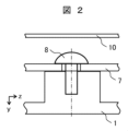
- FIG. 2 is an enlarged cross-sectional view explaining a method of fixing the substrate 7 inside the housing 1.
- the substrate 7 is connected to the housing 1 by screws 8 but has no contact with the cover 10 .
- the imaging apparatus configured as described above is subjected to, for example, severe running vibration during running on an off-road, the imaging module 2 vibrates greatly, degrading the quality of the captured image, and as a result, there is a possibility that the performance of recognizing the external world is also degraded. .
- the circuit elements on the substrate 7 are repeatedly strained under the influence of running vibration, there is a possibility that the soldered portions on the substrate 7 will break.
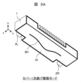
- the cover 10 subjected to running vibration has vibration modes such as a primary cover bending vibration mode M1 (FIG.
- the present invention has been made in view of the above problems, and an object of the present invention is to provide an imaging device capable of reducing vibrations of an imaging module, a substrate, and a cover.
- the present application includes a plurality of means for solving the above problems, and one example is a housing having an open surface, a substrate fixed to the housing by a substrate supporting portion, and the housing. a cover that covers an open surface; and a damping member that connects the cover and the housing and dampens vibration of the cover by elastic deformation, wherein the damping member is a portion from the substrate to the housing-side connection portion.
- the imaging device of the present invention it is possible to reduce vibration of the imaging device (in particular, the cover, substrate, and imaging module).
- FIG. 2 is an external perspective view from above of a conventional imaging device.
- FIG. 2 is an external perspective view from below of a conventional imaging device.
- FIG. 4 is an enlarged cross-sectional view for explaining a substrate fixing method of a conventional imaging device;
- FIG. 11 is a simulated view of a primary bending vibration mode of a cover of a conventional imaging device;
- FIG. 2 is a schematic view of secondary bending vibration mode of a cover of a conventional imaging device.
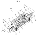
- 1 is a see-through perspective view of an imaging apparatus according to a first embodiment;
- FIG. FIG. 2 is a cross-sectional view of the damping member of Example 1;
- 1 is a perspective view of a damping member of Example 1.
- FIG. 4 is a modification of the damping member of Example 1.
- FIG. 4 is an explanatory diagram of a method of attaching the damping member of the first embodiment; FIG. 4 is an explanatory diagram of the arrangement of the damping members of Example 1; Sectional drawing of the damping member of Example 2.
- FIG. 4 is a perspective view of a damping member of Example 2.
- FIG. 4 is a perspective view of a damping member of Example 2.
- FIG. 4 is a perspective view of a damping member of Example 2.
- FIG. The perspective view of the damping member of Example 3. FIG. The perspective view of the damping member of Example 3.
- FIG. The perspective view of the damping member of Example 5.
- the imaging device 100 of Example 1 of the present invention will be described with reference to FIGS.
- An example in which the imaging device 100 is a stereo camera will be described below, but the imaging device 100 may be a monocular camera.
- the imaging device 100 of this embodiment includes a housing 1, a left imaging module 2L, a right imaging module 2R, a substrate 7 on which a plurality of circuit elements 6 are mounted, a substrate 7 and a cover 10 (not shown).
- the left imaging module 2L includes a left imaging element 3L for imaging the front, a left imaging substrate 4L on which the left imaging element 3L is mounted, and a left lens 5L arranged in front of the left imaging element 3L.
- the right imaging module 2R includes a right imaging element 3R for imaging the front, a right imaging substrate 4R on which the right imaging element 3R is mounted, and a right lens 5R arranged in front of the right imaging element 3R.
- the first circuit element 6a is a microcomputer that processes image signals, a signal processing element, an FPGA (Field Programmable Gate Array), etc., and has a large amount of heat that requires heat conduction to the housing 1, the cover 10, etc. It is a circuit element.
- the second circuit element 6b is a memory or the like used for temporarily storing data
- the third circuit element 6c is an element such as an MPU (Micro Processing Unit) that performs various signal processing. Note that the circuit element 6 is not limited to the elements described above.
- a pair of left and right imaging modules 2 take stereoscopic images of the front of the vehicle, extract feature points common to each other's images from the pair of image information, and determine the positions of the feature points.
- An integrated circuit performs processing to determine the number of pixels (parallax) in which there is a shift between a pair of images, and calculates the distance. Therefore, when the vibration of the housing 1, cover 10, etc. of the imaging device is transmitted to the left and right imaging elements 3 and vibrates, a difference in the amount of vibration occurs in the image, resulting in a difference in distance and speed, resulting in a decrease in measurement accuracy. .
- the allowable amount of deviation against vibration has become smaller, and it has become necessary to reduce the vibration amplitude of the imaging device.
- the vibration is transmitted to the substrate 7, the circuit element 6 mounted on the substrate 7 is repeatedly strained, and there is a possibility that the soldered portion or the like may break.
- it is considered necessary to increase disturbance and widen the frequency band in order to improve the performance of sensors that can handle various environments such as running on rough terrain, so the need to reduce the vibration amplitude is increasing.
- damping member 12 of this embodiment In the imaging apparatus 100 of the present embodiment, as shown in FIG. 4, four damping members 12 are arranged between the housing 1 and the cover 10 to perform both the substrate supporting function and the vibration reducing function. The elastic deformation of these damping members 12 absorbs and attenuates the vibration of the cover 10, and as a result, the vibration amplitude of the imaging module 2, the substrate 7, and the cover 10 is reduced. Details of the structure and operation of the damping member 12 will be described below.
- the damping member 12 of the present embodiment is an elastic body such as silicon rubber having high rigidity in the portion connecting the substrate 7 and the housing 1 and low rigidity in the portion connecting the substrate 7 and the cover 10 . Therefore, the elastic deformation of the damping member 12 is small on the housing side and large on the cover side. Due to such characteristics, the substrate 7 can be rigidly attached to the housing 1 with high rigidity in order to prevent disconnection on the substrate 7 due to vibration, and the vibration mode of the substrate 7 can be increased in frequency. On the other hand, since the vibration mode of the cover 10 tends to occur at low frequencies, the vibration amplitude is reduced by elastic deformation of the damping member 12 .
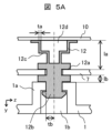
- FIG. 5A is a cross-sectional view of damping member 12 in imaging device 100
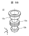
- FIG. 5B is a perspective view of damping member 12.
- the damping member 12 of this embodiment has a substrate support portion 12a, an insertion portion 12b, a deformation portion 12c, and a hollow portion 12d.
- the substrate supporting portion 12a is a portion for supporting the substrate 7, and is, for example, a double flange provided so as to sandwich the substrate 7 from above and below.
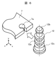
- a method for attaching such a substrate supporting portion 12a to the substrate 7 a method as shown in FIG. 6 is conceivable. That is, in the configuration in which the cut portion 7a is provided at the end portion of the substrate 7, the damping member 12 can be attached to the substrate 7 by inserting the substrate support portion 12a from the side of the cut portion 7a. .
- the insertion portion 12b is a portion for fixing the damping member 12 to the housing 1, and is, for example, a bush that is inserted into the through hole 1b of the board fixing portion 1a of the housing 1 while being elastically deformed. Note that, as shown in FIG. 5A, the tip of the insertion portion 12b has a structure expanded in the radial direction so as to prevent dust and the like from entering the imaging device 100. As shown in FIG.
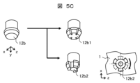
- FIG. 5C is a perspective view for explaining another tip shape of the insertion portion 12b.
- the insertion portion 12b in FIG. 5B has a truncated cone-shaped distal end structure, a cut may be made on the side surface of the truncated cone-shaped distal end as in the insertion portion 12b1, or a truncated cone-shaped distal end as in the insertion portion 12b2.
- a plurality of missing portions may be provided on the side surface of the .
- the insertion portion 12b is more deformable than the insertion portion 12b of FIG.
- the deformable portion 12c is a portion that connects the substrate 7 and the cover 10 and is elastically deformed by running vibration transmitted to the imaging device 100 .
- the deformable portion 12c has a hollow portion 12d inside, thereby lowering rigidity and making it easier to elastically deform.
- the deformable portion 12c has a stepped structure in which circular flat plate portions and true cylinders are alternately stacked to lower the rigidity and promote elastic deformation.
- FIG. 5A illustrates the deformation portion 12c having a stepped structure in which two true cylinders are stacked vertically, a stepped structure in which more true cylinders are stacked may be used if it is desired to further promote elastic deformation. .
- the dimensions of the damping member 12 are designed as follows. That is, the plate thickness ta of the deformation portion 12c is made thinner than the plate thickness tb of the insertion portion 12b, and the distance la between the substrate 7 and the cover 10 is made longer than the distance lb between the substrate 7 and the housing 1. Due to these dimensional features as well, in the damping member 12, the elastic deformation between the substrate 7 and the cover 10 is greater than the elastic deformation between the housing 1 and the substrate 7.
- the damping member 12 of this embodiment has a point-symmetrical shape with respect to the central axis (the dashed-dotted line in the drawing). Since there is no need to worry about the orientation, the structure is easy to assemble. Also, a projection may be provided on the inner surface of the cover 10 and used for positioning when the damping member 12 is brought into contact with the projection.
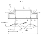
- damping member 12 With respect to cover 10 will be described with reference to FIG. As shown in FIG. 7, considering a plurality of vibration modes of the cover 10 (primary bending vibration mode, secondary bending vibration mode, tertiary bending vibration mode, etc.), it is possible to reduce the vibration amplitude in each vibration mode. Thus, it is desirable to arrange the damping member 12 at a location where the mode amplitude is large.
- the damping member 12 is arranged at a position from L/6 to L/3 from the end face of the cover 10 in the long axis direction. ing. By arranging the damping member 12 in this manner, the vibration amplitude of the cover 10 can be effectively reduced.
- the reduced vibration amplitude of the cover 10 also reduces the noise generated by the cover 10 as a vibrator.
- the damping member 12 also serves as a substrate supporting portion, screws that were conventionally required to fix the substrate 7 can be eliminated, and the number of parts of the imaging device can be reduced. As a result, the imaging device 100 with high performance and high reliability can be manufactured at low cost.
- Example 2 of the present invention An imaging apparatus according to Example 2 of the present invention will be described with reference to FIGS. 8A, 8B, and 9A to 9C.
- the shape of the deformed portion of the damping member is different from that of the deformed portion 12c (FIGS. 5A and 5B) of the first embodiment, which has a stepped structure in which a perfect circular flat plate portion and a perfect cylinder are alternately stacked.
- the structure other than that is the same as that of the first embodiment, redundant description of the points in common with the first embodiment will be omitted.
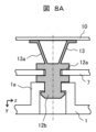
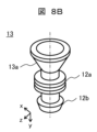
- the damping member 13 of the present embodiment shown in the cross-sectional view of FIG. 8A and the perspective view of FIG. 8B is a slant surface formed by laminating a perfectly circular flat plate portion and a true truncated cone side surface instead of the deformed portion 12c of the first embodiment.
- a deformable portion 13a is provided in the structure, and this slope structure promotes elastic deformation.
- the damping member 14 of the present embodiment shown in the perspective view of FIG. 9A has a deformed portion 14a having a stepped structure in which a regular polygonal annular flat plate portion and a regular polygonal tube are overlapped in place of the deformed portion 12c of the first embodiment. is provided, and this step structure promotes elastic deformation.
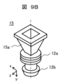
- the damping member 15 of the present embodiment shown in the perspective view of FIG. 9B has a sloped structure in which a regular polygonal annular flat plate portion and a regular polygonal frustum side surface are laminated in place of the deformed portion 12c of the first embodiment.
- a deformable portion 15a is provided, and this slope structure promotes elastic deformation.
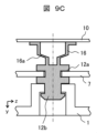
- the deformed portion 16a of the damping member 16 shown in the cross-sectional view of FIG. It is made thinner than other parts, and elastic deformation is promoted in the thin part.
- the following effects can be obtained in addition to the effects of the first embodiment. That is, according to the present embodiment in which the deformed portion has a rectangular shape when viewed from the top, or a portion having a lower rigidity than other portions is intentionally provided in the deformed portion, the deformed portion has a ring shape when viewed from the top and has a uniform thickness. Since the direction of deformation of the damping member is restricted compared to the first embodiment, the damping member having a shape that damps the vibration of the cover 10 can be designed more easily.
- Example 3 of the present invention An imaging device according to Example 3 of the present invention will be described with reference to FIGS. It should be noted that redundant description of the points in common with the above embodiment will be omitted.
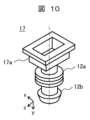
- the damping member 17 of this embodiment shown in the perspective view of FIG. 10 is formed by stacking a polygonal ring (for example, a rectangular ring) flat plate portion having a different aspect ratio and a polygonal cylinder instead of the deformed portion 12c of the first embodiment.
- a deformation portion 17a having a stepped structure is provided, and this stepped structure promotes elastic deformation.
- the damping member 18 of this embodiment shown in the perspective view of FIG. A deformation portion 18a having an overlapping slope structure is provided, and this slope structure promotes elastic deformation.
- the installation position of the damping member may deviate slightly from the reference position.
- the damping member includes a large area (located from L/6 to L/3 from the longitudinal end face of the cover (see FIG. 7)) in which the vibration amplitude can be reduced in a plurality of vibration modes of the cover 10. , the vibration of the cover 10 can be appropriately reduced even if there are variations in manufacturing and assembly of each damping member.
- Example 4 of the present invention An imaging device according to Example 4 of the present invention will be described with reference to FIG. It should be noted that redundant description of the points in common with the above embodiment will be omitted.
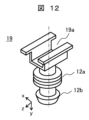
- the damping member 19 of the present embodiment shown in the perspective view of FIG. 12 is a further improvement of the deformed portion 17a (FIG. 10) of the third embodiment.
- a divided deformation portion 19a is provided.
- Example 5 of the present invention An imaging device according to Example 5 of the present invention will be described with reference to FIGS. 13A and 13B. It should be noted that redundant description of the points in common with the above embodiment will be omitted.
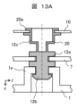
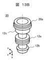
- the damping member 20 of this embodiment shown in FIGS. 13A and 13B has a mounting structure 20a for mounting the damping member 20 to the opening of the cover 10A at the cover-side end of the deformation portion 12c.
- the damping member 20 can be reliably connected to the cover 10A, and the vibration of the cover 10A can be reduced more effectively.
- the mounting structure 20a of the damping member 20 is a double flange structure, the damping member 20 can be easily mounted on the cover 10A by making the diameter of the cover outer surface side flange smaller than the cover inner surface side flange diameter.
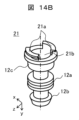
- Example 6 of the present invention An imaging apparatus according to Example 6 of the present invention will be described with reference to FIGS. 14A and 14B. Duplicate descriptions of the points in common with the fifth embodiment will be omitted.
- the damping member 21 of this embodiment shown in FIGS. 14A and 14B is a further improvement of the mounting structure 20a of Embodiment 5, and the mounting structure 21a divided into two parts is inserted into the holes 11 provided at two locations in the cover 10B. and fixed, thereby sealing the hollow portion 12d.
- the vibration amplitude of the cover 10B can be further reduced because the closed hollow portion 12d functions as an air damper.
- the present invention is not limited to the above embodiments, and includes various modifications and combinations within the scope that does not deviate from the gist of the invention. Moreover, the present invention is not limited to those having all the configurations described in the above embodiments, and includes those having some of the configurations omitted.
Landscapes
- Physics & Mathematics (AREA)
- General Physics & Mathematics (AREA)
- Stereoscopic And Panoramic Photography (AREA)
- Camera Bodies And Camera Details Or Accessories (AREA)
- Studio Devices (AREA)
Abstract
撮像素子などのセンサへの振動を低減できる、車両への搭載に好適な撮像装置を提供すること。開放面を持つ筐体(1)と、前記筐体に対して基板支持部によって固定された基板(7)と、前記筐体の開放面を覆うカバー(10)と、前記カバーと前記筐体とを接続し、弾性変形によって、前記カバーの振動を減衰させる減衰部材(12)と、を備え、前記減衰部材は、前記基板から筐体側接続部までの部位より前記基板からカバー側接続部までの部位が弾性変形しやすい構造体である撮像装置(100)。
Description
本発明は、車両に搭載され、自車前方を撮像する撮像装置に関する。
近年、安全かつ快適な車社会の実現を目指して、運転者支援システムの実車搭載が進んでいる。その中で、障害物への衝突前に自動的に減速する衝突被害軽減制動システムや、先行車との車間距離を略一定距離に維持しながら自動追尾する車間自動制御システムや、車線逸脱抑制システムや、標識認識システムなど、運転者や搭乗者の安全性と利便性と快適性を追求したシステムの開発が進んでいる。このような運転者支援システムの実現には、車両や歩行者や路面などを認識したり、対象物までの距離を計測したりする外界認識システムが必要である。
ここで、外界認識システムの入力装置の一種である、従来の撮像装置(ステレオカメラ)を説明する。図1Aは、従来の撮像装置の上方からの外観斜視図であり、図1Bは、従来の撮像装置の下方からの外観斜視図である。なお、この撮像装置は、撮像装置のx軸正方向が車両の進行方向、y軸正方向が車両の上方向、z軸正方向が車両の右方向と一致するように車両に取り付けられているものとする。
この撮像装置は、上面にフィンを有し内部に空間を有する、金属製(例えば、アルミダイカスト)の筐体1と、筐体1の開放面(背面および底面)を覆う、金属製(例えば、アルミ板)のカバー10と、車両の前方をステレオ撮像する左右の撮像モジュール2(2L、2R)を備えている。そして、カバー10を複数のネジ10aで固定することで筐体1を密閉し、筐体内部の撮像モジュール2や基板7等の防塵性、放熱性、ノイズ耐性を確保している。なお、図示を省略しているが、カバー10の一部(例えば、背面)からは、車両の制御装置(ECU等)と通信接続するためのコネクタが露出している。
図2は、筐体1の内部に基板7を固定する方法を説明する拡大断面図である。ここに示すように、基板7は、筐体1とはネジ8で連結される一方、カバー10とは接触が無い。
外界認識装置で外界を正確に認識するためには、撮像装置の明確な視野の確保が必要である。しかし、前記した構成の撮像装置に、例えば不整地走行中の激しい走行振動が加わると、撮像モジュール2が大きく振動し、撮像画像の品質が劣化する結果、外界認識性能も劣化する可能性がある。また、走行振動の影響を受け、基板7上の回路素子に繰り返しひずみが加わると、基板7上のはんだ部などに断線が生じる可能性がある。さらに、走行振動を受けたカバー10には、カバー1次曲げ振動モードM1(図3A)や、カバー2次曲げ振動モードM2(図3B)などの振動モードが生じるが、軽量化とコスト低減のためにカバー10を薄くすると、振動モードが低周波数で生じやすく、カバー10がスピーカのように振動し、騒音も生じやすい。加えて、カバー10の振動モードが低周波数になると、筐体1の振動モードと共振しやすくなるという問題もある。
このように、従来の撮像装置には、撮像モジュールの振動低減、基板の振動低減、カバーの振動低減による振動モード周波数帯域の広域化、および、筐体とカバーの共振対策が必要であった。
本発明は上記問題に鑑みてなされたものであり、撮像モジュールと基板とカバーの振動を低減することができる撮像装置を提供することを目的とする。
本願は上記課題を解決する手段を複数含んでいるが、その一例を挙げるならば、開放面を持つ筐体と、前記筐体に対して基板支持部によって固定された基板と、前記筐体の開放面を覆うカバーと、前記カバーと前記筐体とを接続し、弾性変形によって前記カバーの振動を減衰させる減衰部材と、を備え、前記減衰部材は、前記基板から筐体側接続部までの部位より前記基板からカバー側接続部までの部位が弾性変形しやすい構造体であることにより、達成される。
本発明の撮像装置によれば、撮像装置(特に、カバー、基板、撮像モジュール)の振動を低減することができる。
以下、本発明の撮像装置の実施例について、図面を用いて説明する。なお、上記した従来の撮像装置(図1A、図1B)との共通点については重複説明を省略する。
まず、本発明の実施例1の撮像装置100を、図4~7を用いて説明する。なお、以下では、撮像装置100がステレオカメラである例を説明するが、撮像装置100は単眼カメラであっても良い。
図4の透視斜視図に示すように、本実施例の撮像装置100は、筐体1と、左撮像モジュール2Lと、右撮像モジュール2Rと、複数の回路素子6を搭載する基板7と、基板7を支持する減衰部材12と、カバー10(図示せず)を備えている。
左撮像モジュール2Lは、前方を撮像する左撮像素子3Lと、左撮像素子3Lを搭載した左撮像基板4Lと、左撮像素子3Lの前方に配置した左レンズ5Lを備えている。同様に、右撮像モジュール2Rは、前方を撮像する右撮像素子3Rと、右撮像素子3Rを搭載した右撮像基板4Rと、右撮像素子3Rの前方に配置した右レンズ5Rを備えている。
基板7には、回路素子6(6a~6c)が搭載されている。第1回路素子6aは、画像信号を処理するマイコンや信号処理素子、FPGA(Field Programmable Gate Array)などであり、筐体1やカバー10などへの熱伝導を必要とするような発熱量が大きい回路素子である。第2回路素子6bは、データの一時保管に用いるメモリなどであり、第3回路素子6cは、MPU(Micro Processing Unit)など各種の信号処理を行う素子である。なお、回路素子6は上記素子に限定するものではない。
この種の撮像装置(ステレオカメラ)では、左右一対の撮像モジュール2で車両の前方をステレオ撮像し、一対の画像情報の中から相互の画像に共通する特徴点を抽出し、その特徴点の位置が一対の画像間でずれている画素数(視差)を求める処理を集積回路で行い、距離を算出する。そのため、撮像装置の筐体1やカバー10などの振動が、左右の撮像素子3に伝わり振動すると、画像に振動分の差が生じ、距離や速度の差となって、測定精度の低下が生じる。また、広画角化や高精度や高速対応などの撮像装置の高性能化にともなって、振動に対するずれの許容量が小さくなり、撮像装置の振動振幅を低減する必要が生じた。さらに振動が基板7に伝わると、基板7に搭載されている回路素子6に繰り返しひずみが加わり、はんだ部などに断線が生じる可能性がある。特に不整地走行など各種環境に対応するセンサの高性能化には、外乱の増加や周波数帯域の広域化が必要と考えられるので、振動振幅の低減の必要性は増している。
これらの課題を考慮し、本実施例の撮像装置100では、従来の撮像装置で使用していた、図2のネジ8に代え、減衰部材12を利用することで、筐体1と基板7とカバー10の三者の振動振幅を低減できるようにした。
<本実施例の減衰部材12の構造>
本実施例の撮像装置100では、図4に示すように、筐体1とカバー10の間に、基板支持機能と振動低減機能の双方を担う、4つの減衰部材12を配置した。そして、これらの減衰部材12の弾性変形によってカバー10の振動を吸収・減衰させ、その結果として、撮像モジュール2、基板7、カバー10の振動振幅の低減を図っている。以下、減衰部材12の構造や作用の詳細を順次説明する。
本実施例の撮像装置100では、図4に示すように、筐体1とカバー10の間に、基板支持機能と振動低減機能の双方を担う、4つの減衰部材12を配置した。そして、これらの減衰部材12の弾性変形によってカバー10の振動を吸収・減衰させ、その結果として、撮像モジュール2、基板7、カバー10の振動振幅の低減を図っている。以下、減衰部材12の構造や作用の詳細を順次説明する。
本実施例の減衰部材12は、基板7と筐体1を繋ぐ部位が高剛性で、基板7とカバー10を繋ぐ部位が低剛性の、シリコンゴム等の弾性体である。従って、減衰部材12の弾性変形は、筐体側で小さく、カバー側で大きくなる。このような特性により、振動による基板7上での断線を防ぐべく、剛性の高い筐体1に基板7を剛に取付けることができ、基板7の振動モードの高域化を図っている。それに対して、カバー10の振動モードは低周波で生じやすいので、減衰部材12の弾性変形で振動振幅の低減を図っている。
図5Aは、撮像装置100内の減衰部材12の断面図であり、図5Bは、減衰部材12の斜視図である。これらに示すように、本実施例の減衰部材12は、基板支持部12aと、挿入部12bと、変形部12cと、中空部12dを有している。
基板支持部12aは、基板7を支持するための部位であり、例えば、基板7を上下から挟み込むように設けられた二重フランジである。このような基板支持部12aを基板7に取り付ける方法としては、図6のような方法が考えられる。すなわち、基板7の端部に切込部7aを設けた構成であれば、この切込部7aの側方から基板支持部12aを挿入することで、基板7に減衰部材12を取り付けることができる。
挿入部12bは、減衰部材12を筐体1に固定するための部位であり、例えば、筐体1の基板固定部1aの貫通孔1bに弾性変形しながら挿入されるブッシュである。なお、図5Aに示すように、挿入部12bの先端は、撮像装置100内へのほこり等の侵入を防ぐことができるよう径方向に拡大した構造となっている。
図5Cは、挿入部12bの先端形状の別案を説明する斜視図である。図5Bの挿入部12bは、円錐台状の先端構造であったが、挿入部12b1のように円錐台状先端の側面に切れ目を入れても良いし、挿入部12b2のように円錐台状先端の側面に複数の欠落部を設けても良い。何れの場合も、図5Bの挿入部12bより変形しやすくなるため、減衰部材12を筐体1に固定する組立作業の組立性をより向上させることができる。なお、挿入部12b2を用いる場合、筐体1の外面側に挿入部12b2の上面視形状と符合する凹み(図5Cの右下図の破線)を設けておくことが望ましい。これにより、挿入部12b2を矢印方向に回転させることで、挿入部12b2を凹みに嵌め、減衰部材12の回転を防止することができる。
変形部12cは、基板7とカバー10を繋ぎ、また、撮像装置100に伝わった走行振動によって弾性変形する部位である。この変形部12cは、内側に中空部12dを設けることで剛性を低くして、弾性変形しやすくしている。また、変形部12cは、図5Aと図5Bに示すように、真円環状の平板部と真円筒を交互に重ねた段差構造を設けることによっても剛性を低くして、弾性変形を促進している。なお、図5Aには、2つの真円筒を上下に重ねた段差構造の変形部12cを例示したが、弾性変形をさらに促進したい場合は、より多くの真円筒を重ねた段差構造にしても良い。
また、変形部12cの剛性を、挿入部12bの剛性より低くするため、減衰部材12の寸法を次のように設計している。すなわち、変形部12cの板厚taを、挿入部12bの板厚tbより薄くし、また、基板7とカバー10の距離laを、基板7と筐体1の距離lbより長くしている。これらの寸法的な特徴によっても、減衰部材12においては、筐体1と基板7の間の弾性変形より、基板7とカバー10の間の弾性変形が大きくなる。
なお、図5Bから明らかなように、本実施例の減衰部材12は、中心軸(図中の一点鎖線)に対して点対称の形状であり、減衰部材12を筐体1に取り付ける際に周方向の向きを気にする必要がないため、組立てが容易な構造となっている。また、カバー10の内面に突起を設け、減衰部材12と接触させる際の位置決めに用いてもよい。
<減衰部材12の設置位置>
ここで、図7を用いて、カバー10に対する、減衰部材12の配置を説明する。図7に示すように、カバー10の複数の振動モード(1次曲げ振動モード、2次曲げ振動モード、3次曲げ振動モード、等)を考慮すると、各振動モードで振動振幅の低減が可能なように、モード振幅が大きい個所に減衰部材12を配置することが望ましい。
ここで、図7を用いて、カバー10に対する、減衰部材12の配置を説明する。図7に示すように、カバー10の複数の振動モード(1次曲げ振動モード、2次曲げ振動モード、3次曲げ振動モード、等)を考慮すると、各振動モードで振動振幅の低減が可能なように、モード振幅が大きい個所に減衰部材12を配置することが望ましい。
そのため、本実施例では、カバー10の長軸方向(z軸方向)の長さLとすると、カバー10の長軸方向端面からL/6からL/3の位置に、減衰部材12を配置している。このように減衰部材12を配置すると、カバー10の振動振幅を効果的に低減することができる。
<本実施例の効果>
以上で説明したように、筐体1とカバー10を減衰部材12で接続し、かつ、減衰部材12の筐体側よりカバー側を低剛性にすることにより、カバー10の振動振幅を低減できるとともに、カバー10と筐体1間の振動を遮断し共振を防ぎ、左右の撮像素子3への振動振幅が低減できる。そして、振動振幅を低減することによって、撮像画像の振動も抑制されるため、対象物の位置と速度などの認識を高精度に測定できる。また、基板7に加わる繰り返しひずみも低減され、基板7上のはんだ部などの断線を回避することができる。さらに、カバー10の振動振幅の低減により、カバー10を振動子として発生する騒音も低減される。加えて、減衰部材12が基板支持部を兼ねることにより、従前は基板7を固定するために必要であったネジを削減でき撮像装置の部品点数を低減することができる。これらの結果、高性能で信頼性の高い撮像装置100を低コストで製造することができる。
以上で説明したように、筐体1とカバー10を減衰部材12で接続し、かつ、減衰部材12の筐体側よりカバー側を低剛性にすることにより、カバー10の振動振幅を低減できるとともに、カバー10と筐体1間の振動を遮断し共振を防ぎ、左右の撮像素子3への振動振幅が低減できる。そして、振動振幅を低減することによって、撮像画像の振動も抑制されるため、対象物の位置と速度などの認識を高精度に測定できる。また、基板7に加わる繰り返しひずみも低減され、基板7上のはんだ部などの断線を回避することができる。さらに、カバー10の振動振幅の低減により、カバー10を振動子として発生する騒音も低減される。加えて、減衰部材12が基板支持部を兼ねることにより、従前は基板7を固定するために必要であったネジを削減でき撮像装置の部品点数を低減することができる。これらの結果、高性能で信頼性の高い撮像装置100を低コストで製造することができる。
本発明の実施例2の撮像装置を、図8A、B、および、図9A~Cを用いて説明する。なお、本実施例は、減衰部材の変形部の形状を、真円環状の平板部と真円筒を交互に重ねた段差構造の実施例1の変形部12c(図5A、図5B)と異ならせたものであるが、それ以外の構造は実施例1と同等であるので、実施例1との共通点については重複説明を省略することとする。
図8Aの断面図、および、図8Bの斜視図に示す、本実施例の減衰部材13は、実施例1の変形部12cに代え、真円環状の平板部と真円錐台側面を積層した斜面構造の変形部13aを設け、この斜面構造で弾性変形を促進したものである。
また、図9Aの斜視図に示す、本実施例の減衰部材14は、実施例1の変形部12cに代え、正多角形環状の平板部と正多角形筒を重ねた段差構造の変形部14aを設け、この段差構造で弾性変形を促進したものである。同様に、図9Bの斜視図に示す、本実施例の減衰部材15は、実施例1の変形部12cに代え、正多角形環状の平板部と正多角形錐台側面を積層した斜面構造の変形部15aを設け、この斜面構造で弾性変形を促進したものである。
さらに、図9Cの断面図に示す、減衰部材16の変形部16aは、実施例1の変形部12cに代え、段差構造の一部(例えば、カバー10と略平行な平板部)の厚さを他の部位より薄くし、厚さの薄い部位で弾性変形を促進したものである。
以上で説明した、本実施例の撮像装置100によれば、実施例1の効果以外に次の効果を得ることができる。すなわち、変形部が上面視四角形状である、あるいは、変形部に敢えて他の部位より剛性の弱い部位を設けた本実施例によれば、変形部が上面視環状でありその厚さも一様である実施例1に比べ、減衰部材の変形方向が制限されることから、カバー10の振動を減衰させる形状の減衰部材をより容易に設計することができる。
本発明の実施例3の撮像装置を、図10、11を用いて説明する。なお、上記実施例との共通点は重複説明を省略する。
図10の斜視図に示す本実施例の減衰部材17は、実施例1の変形部12cに代え、縦横比の異なる多角形環(例えば、長方形環)状の平板部と多角形筒を重ねた段差構造の変形部17aを設け、この段差構造で弾性変形を促進したものである。同様に、図11の斜視図に示す本実施例の減衰部材18は、実施例1の変形部12cに代え、縦横比の異なる円環(例えば、楕円環)状の平板部と円錐台側面を重ねた斜面構造の変形部18aを設け、この斜面構造で弾性変形を促進したものである。
両図のように、減衰部材17,18の縦横比を異ならせた場合、減衰部材の長手方向とカバーの長手方向を一致させるように取り付ければ、減衰部材の設置位置が基準位置から多少ずれても、その減衰部材は、カバー10の複数の振動モードで振動振幅の低減が可能な領域(カバーの長軸方向端面からL/6からL/3の位置(図7参照))を大きく含むため、各減衰部材の製造バラツキや組立てバラツキがあっても、カバー10の振動を適切に低減させることができる。
本発明の実施例4の撮像装置を、図12を用いて説明する。なお、上記実施例との共通点は重複説明を省略する。
図12の斜視図に示す本実施例の減衰部材19は、実施例3の変形部17a(図10)を更に改良したものであり、変形部の長手方向伸びるスリット(切欠)で、周方向に分割された変形部19aを設けたものである。このように変形部19aを分割することによって、変形部19aの撓みにくい方向(スリット方向)と、撓みやすい方向(スリットと直交する方向)ができるため、板厚等の形状管理で弾性変形をコントロールしやすい構造となる。なお、スリットの位置や数は図12に例示するものに限定されず、必要とされる仕様に応じて、任意のスリットを設けても良い。
本発明の実施例5の撮像装置を、図13A、図13Bを用いて説明する。なお、上記実施例との共通点は重複説明を省略する。
図13A、図13Bに示す本実施例の減衰部材20は、変形部12cのカバー側端部に、減衰部材20をカバー10Aの開口部に取り付けるための取付け構造20aを設けたものである。この取付け構造20aによって、減衰部材20をカバー10Aに確実に接続することができ、カバー10Aの振動をより効果的に低減することができる。なお、減衰部材20の取付け構造20aを二重フランジ構造とした場合、カバー外面側フランジの径を、カバー内面側フランジの径より小さくすると、カバー10Aへの減衰部材20の取り付けが容易となる。
本発明の実施例6の撮像装置を、図14A、図14Bを用いて説明する。なお、実施例5との共通点は重複説明を省略する。
図14A、図14Bに示す本実施例の減衰部材21は、実施例5の取付け構造20aを更に改良したものであり、二分割した取付け構造21aをカバー10Bの2箇所に設けた孔11に挿入して固定し、これにより中空部12dを密閉したものである。
本実施例によれば、実施例5と同等の効果が得られるだけでなく、密閉状態の中空部12dがエアーダンパとして機能することにより、カバー10Bの振動振幅を更に低減することができる。
なお、本発明は上記の実施例に限定されるものではなく、その要旨を逸脱しない範囲内の様々な変形例や組み合わせが含まれる。また、本発明は、上記の実施例で説明した全ての構成を備えるものに限定されず、その構成の一部を削除したものも含まれる。
100…撮像装置
1…筐体
1a…基板固定部
1b…貫通孔
2…撮像モジュール
3…撮像素子
4…撮像基板
5…レンズ
6…回路素子
6a…第1回路素子
6b…第2回路素子
6c…第3回路素子
7…基板
7a…切込部
8…ネジ
10、10A、10B…カバー
11…孔
12…実施例1の減衰部材
12a…基板支持部
12b…挿入部
12c…変形部
12d…中空部
13~16…実施例2の減衰部材
17、18…実施例3の減衰部材
19…実施例4の減衰部材
13a~19a…弾性変形部
20…実施例5の減衰部材
20a…取付け構造
21…実施例6の減衰部材
21a…取付け構造
1…筐体
1a…基板固定部
1b…貫通孔
2…撮像モジュール
3…撮像素子
4…撮像基板
5…レンズ
6…回路素子
6a…第1回路素子
6b…第2回路素子
6c…第3回路素子
7…基板
7a…切込部
8…ネジ
10、10A、10B…カバー
11…孔
12…実施例1の減衰部材
12a…基板支持部
12b…挿入部
12c…変形部
12d…中空部
13~16…実施例2の減衰部材
17、18…実施例3の減衰部材
19…実施例4の減衰部材
13a~19a…弾性変形部
20…実施例5の減衰部材
20a…取付け構造
21…実施例6の減衰部材
21a…取付け構造
Claims (10)
- 開放面を持つ筐体と、前記筐体に対して基板支持部によって固定された基板と、前記筐体の開放面を覆うカバーと、前記カバーと前記筐体とを接続し、弾性変形によって前記カバーの振動を減衰させる減衰部材と、を有し、
前記減衰部材は、前記基板から筐体側接続部までの部位より前記基板からカバー側接続部までの部位が弾性変形しやすい構造体であることを特徴とする撮像装置。 - 請求項1に記載の撮像装置であって、
前記減衰部材は、前記基板支持部によって前記基板が固定されている箇所に設けられることを特徴とする撮像装置。 - 請求項1に記載の撮像装置であって、
前記減衰部材は、前記基板支持部と一体であることを特徴とする撮像装置。 - 請求項1に記載の撮像装置であって、
前記減衰部材は、前記基板から前記カバー側接続部までの部位に中空構造を有することを特徴とする撮像装置。 - 請求項1に記載の撮像装置であって、
前記減衰部材は、前記基板から前記筐体までの距離より、前記基板から前記カバーまでの距離が長いことを特徴とする撮像装置。 - 請求項1に記載の撮像装置であって、
前記減衰部材は、前記カバー側接続部に径の異なる筒状体を重ねた構造であることを特徴とする撮像装置。 - 請求項1に記載の撮像装置であって、
前記減衰部材は、前記カバー側接続部が前記カバーの長軸方向に長いことを特徴とする撮像装置。 - 請求項1に記載の撮像装置であって、
前記減衰部材は、ブッシュ構造で前記筐体に取り付けられることを特徴とする撮像装置。 - 請求項8に記載の撮像装置であって、
前記減衰部材は、二重フランジ構造で前記カバーに取り付けられることを特徴とする撮像装置。 - 開放面を持つ筐体と、前記筐体に対して基板支持部によって固定された基板と、前記筐体の開放面を覆うカバーと、前記カバーと前記筐体とを接続し、弾性変形によって前記カバーの振動を減衰させる減衰部材と、を有し、
前記減衰部材は、前記基板から筐体側接続部までの部位より前記基板からカバー側接続部までの部位の剛性が小さいことを特徴とする撮像装置。
Applications Claiming Priority (2)
| Application Number | Priority Date | Filing Date | Title |
|---|---|---|---|
| JP2021-186910 | 2021-11-17 | ||
| JP2021186910A JP7813562B2 (ja) | 2021-11-17 | 2021-11-17 | 撮像装置 |
Publications (1)
| Publication Number | Publication Date |
|---|---|
| WO2023089989A1 true WO2023089989A1 (ja) | 2023-05-25 |
Family
ID=86396817
Family Applications (1)
| Application Number | Title | Priority Date | Filing Date |
|---|---|---|---|
| PCT/JP2022/037964 Ceased WO2023089989A1 (ja) | 2021-11-17 | 2022-10-12 | 撮像装置 |
Country Status (2)
| Country | Link |
|---|---|
| JP (1) | JP7813562B2 (ja) |
| WO (1) | WO2023089989A1 (ja) |
Families Citing this family (1)
| Publication number | Priority date | Publication date | Assignee | Title |
|---|---|---|---|---|
| JPWO2024225136A1 (ja) | 2023-04-28 | 2024-10-31 |
Citations (5)
| Publication number | Priority date | Publication date | Assignee | Title |
|---|---|---|---|---|
| JP2006180094A (ja) * | 2004-12-21 | 2006-07-06 | Nikon Corp | 電子カメラ |
| JP2011249380A (ja) * | 2010-05-24 | 2011-12-08 | Nikon Corp | 電子機器およびカメラ |
| JP2013092588A (ja) * | 2011-10-24 | 2013-05-16 | Sharp Corp | ステレオ撮像装置および電子情報機器 |
| JP2018085614A (ja) * | 2016-11-23 | 2018-05-31 | 日本電産コパル株式会社 | 撮像装置 |
| WO2019176669A1 (ja) * | 2018-03-15 | 2019-09-19 | 日立オートモティブシステムズ株式会社 | ステレオカメラ装置 |
-
2021
- 2021-11-17 JP JP2021186910A patent/JP7813562B2/ja active Active
-
2022
- 2022-10-12 WO PCT/JP2022/037964 patent/WO2023089989A1/ja not_active Ceased
Patent Citations (5)
| Publication number | Priority date | Publication date | Assignee | Title |
|---|---|---|---|---|
| JP2006180094A (ja) * | 2004-12-21 | 2006-07-06 | Nikon Corp | 電子カメラ |
| JP2011249380A (ja) * | 2010-05-24 | 2011-12-08 | Nikon Corp | 電子機器およびカメラ |
| JP2013092588A (ja) * | 2011-10-24 | 2013-05-16 | Sharp Corp | ステレオ撮像装置および電子情報機器 |
| JP2018085614A (ja) * | 2016-11-23 | 2018-05-31 | 日本電産コパル株式会社 | 撮像装置 |
| WO2019176669A1 (ja) * | 2018-03-15 | 2019-09-19 | 日立オートモティブシステムズ株式会社 | ステレオカメラ装置 |
Also Published As
| Publication number | Publication date |
|---|---|
| JP2023074129A (ja) | 2023-05-29 |
| JP7813562B2 (ja) | 2026-02-13 |
Similar Documents
| Publication | Publication Date | Title |
|---|---|---|
| US11882350B2 (en) | Camera module | |
| JP6308147B2 (ja) | 車載用センサの取付構造 | |
| JP2014066948A (ja) | ステレオカメラ装置 | |
| JP2023074129A (ja) | 撮像装置 | |
| US20220340089A1 (en) | Device for vehicle, mounting unit of device for vehicle | |
| US12069226B2 (en) | Imaging device | |
| EP3288250B1 (en) | Imaging device | |
| JP2003335180A (ja) | センサの支持構造およびその組付方法 | |
| US12563282B2 (en) | Vehicular camera | |
| JP6896119B1 (ja) | 車載カメラ | |
| JP7635084B2 (ja) | 撮像装置 | |
| JP6935029B1 (ja) | 電子機器、車載装置、電子機器の組み立て方法、車載装置の取り付け方法 | |
| US20050066724A1 (en) | Acceleration sensor unit | |
| EP3846435B1 (en) | Electronic apparatus, image capture device, and mobile body | |
| JP5166969B2 (ja) | レンズ組立体および撮像装置 | |
| JP2014127930A (ja) | 車載カメラ装置 | |
| US20250274646A1 (en) | Vehicular camera | |
| KR101131245B1 (ko) | 자동차의 통합 전자제어장치 | |
| KR20250146686A (ko) | 차량용 전방 카메라 모듈 및 그 제조 방법 | |
| US20250142190A1 (en) | Vehicular camera | |
| US20250277955A1 (en) | Vehicular camera | |
| US20250386087A1 (en) | Vehicular camera | |
| JP6204784B2 (ja) | 接続ポート装置 | |
| WO2025173432A1 (ja) | カメラモジュール、撮像システム、及び移動体 | |
| WO2026063289A1 (ja) | カメラモジュール、車載システム、及び移動体 |
Legal Events
| Date | Code | Title | Description |
|---|---|---|---|
| 121 | Ep: the epo has been informed by wipo that ep was designated in this application |
Ref document number: 22895275 Country of ref document: EP Kind code of ref document: A1 |
|
| 122 | Ep: pct application non-entry in european phase |
Ref document number: 22895275 Country of ref document: EP Kind code of ref document: A1 |