WO2023089891A1 - スクレーパ車両および牽引車両 - Google Patents
スクレーパ車両および牽引車両 Download PDFInfo
- Publication number
- WO2023089891A1 WO2023089891A1 PCT/JP2022/031602 JP2022031602W WO2023089891A1 WO 2023089891 A1 WO2023089891 A1 WO 2023089891A1 JP 2022031602 W JP2022031602 W JP 2022031602W WO 2023089891 A1 WO2023089891 A1 WO 2023089891A1
- Authority
- WO
- WIPO (PCT)
- Prior art keywords
- scraper
- vehicle
- control device
- towing
- excavation
- Prior art date
- Legal status (The legal status is an assumption and is not a legal conclusion. Google has not performed a legal analysis and makes no representation as to the accuracy of the status listed.)
- Ceased
Links
Images



Classifications
-
- E—FIXED CONSTRUCTIONS
- E02—HYDRAULIC ENGINEERING; FOUNDATIONS; SOIL SHIFTING
- E02F—DREDGING; SOIL-SHIFTING
- E02F3/00—Dredgers; Soil-shifting machines
- E02F3/04—Dredgers; Soil-shifting machines mechanically-driven
- E02F3/64—Buckets cars, i.e. having scraper bowls
- E02F3/65—Component parts, e.g. drives, control devices
-
- E—FIXED CONSTRUCTIONS
- E02—HYDRAULIC ENGINEERING; FOUNDATIONS; SOIL SHIFTING
- E02F—DREDGING; SOIL-SHIFTING
- E02F3/00—Dredgers; Soil-shifting machines
- E02F3/04—Dredgers; Soil-shifting machines mechanically-driven
- E02F3/76—Graders, bulldozers, or the like with scraper plates or ploughshare-like elements; Levelling scarifying devices
Definitions
- the present invention relates to a scraper vehicle and a tow vehicle with an excavable scraper.
- scraper vehicles equipped with scrapers for excavating the ground or the like have been used at civil engineering sites.
- This scraper vehicle has rear wheels, which can be assisted by an electric motor.
- the scraper vehicle is towed by a tractor having an internal combustion engine, and is normally driven by the tractive force of the tractor, with the rear wheels being assisted by an electric motor as needed.
- Patent Document 1 does not disclose any distortion of the scraper vehicle caused by excavation. Further, Patent Document 1 does not disclose any control by the tractor caused by the distortion of the scraper vehicle caused by excavation.
- an object of the present invention is to provide a scraper vehicle capable of detecting distortion of the scraper vehicle caused by excavation.
- Another object of the present invention is to provide a towing vehicle that can control the scraper vehicle due to distortion of the scraper vehicle.
- a scraper vehicle is a movable scraper vehicle, and includes a scraper that excavates the ground during movement, and a detection device that is provided on the scraper vehicle and detects a change in strain due to excavation by the scraper. ing.
- a towing vehicle according to the present invention is a towing vehicle that tows a scraper vehicle having a scraper that excavates the ground during movement, and includes a detection device that is provided on the scraper vehicle and detects a change in strain due to excavation by the scraper.
- a receiving device is provided for receiving the detection results.
- the detector detects a change in the strain of the scraper due to excavation, it is possible to realize a scraper vehicle that can detect the strain of the scraper vehicle caused by excavation.
- the receiving device receives the detection result of the detecting device that detects the change in strain due to excavation of the scraper. can do.
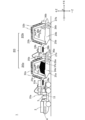
- FIG. 2 is a block diagram of main parts of the scraper vehicle of the first embodiment;
- FIG. It is a figure which shows the load cell provided under the axle of 1st Embodiment.
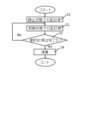
- 4 is a flowchart executed by a scraper vehicle control device;
- 4 is a flow chart executed by a towing vehicle controller;
- It is a schematic diagram which shows the towing vehicle and scraper vehicle of 2nd Embodiment.
- FIG. 1 is a schematic diagram showing a towing vehicle 1 and a scraper vehicle 20, which are driving vehicles of the first embodiment.
- FIG. 2 is a block diagram of main parts of the towing vehicle 1 and the scraper vehicle 20 of the first embodiment.
- One cycle of the scraper vehicle 20 includes an excavating process, a transporting process, a discharging process, and a forwarding process.
- the towing vehicle 1 tows a scraper vehicle 20, and is connected (coupled) to the scraper vehicle 20 by a hitch 21, which is a coupling device.
- the hitch 21 is detachable from the towing vehicle 1 and has a flexible ball joint 22 provided at one end on the towing vehicle 1 side.
- the towing vehicle 1 of the present embodiment is of automatic driving type without a driver's seat. Further, in this embodiment, instead of the internal combustion engine, the towing vehicle 1 uses a fuel cell 2 and in-wheel motors 3 (see FIG. 2) provided for each of the two front wheels and the four rear wheels. is running (driving). Note that the in-wheel type motor 3 may be provided so as to be coaxially connected to the hubs of the front and rear wheels.
- the towing vehicle 1 may be of a remote control type, a type having a driver's seat, an engine using an internal combustion engine, or an engine driven by ammonia or hydrogen as fuel.
- the towing vehicle 1 of this embodiment includes a hydrogen tank 4 that supplies hydrogen to the fuel cell 2, a storage battery 5, a GNSS 6 (Global Navigation Satellite System), a speedometer 7, a communication device 8, and a memory 9. , and a control device 10 .
- GNSS 6 Global Navigation Satellite System
- the fuel cell 2 is a power generator that produces electricity by causing an electrochemical reaction between hydrogen and oxygen.
- the hydrogen tank 4 stores hydrogen compressed to several tens of MPa, and supplies the hydrogen to the fuel cell 2 via a hydrogen supply channel (not shown).
- the storage battery 5 is a secondary battery that stores electric power generated by the fuel cell 2 .
- the storage battery 5 can supply the stored electric power to the motor 3, the storage battery 33 provided in the scraper vehicle 20, and the like.
- the towing vehicle 1 is provided with a first connector 11 (e.g., a female connector) connected to the storage battery 5 , and the scraper vehicle 20 is engaged with the first connector 11 .
- a mating second connector 35 (eg a male connector) is provided.
- the fuel cell 2 and the hydrogen tank 4 are arranged on the front side of the towing vehicle 1.
- an internal combustion engine was arranged and a driver's seat was provided.
- a large space can be provided in front of the towing vehicle 1, and many hydrogen tanks 4 can be arranged, and the fuel cell 2 can be arranged freely. can be secured.
- the storage battery 5 is shown near the center of the towing vehicle 1 in FIG.
- GNSS6 measures the position of the traction vehicle 1 using an artificial satellite.
- the speedometer 7 detects the speed of the towing vehicle 1, and various sensors such as a vehicle speed sensor that detects the number of rotations of a shaft connected to the driving wheels and a sensor that uses the output of the GNSS 6 can be applied. can.
- the communication device 8 is a wireless communication unit that accesses a communication device 40 (to be described later) provided on the scraper vehicle 20 side and a wide area network such as the Internet. drive and control information to the communication device 40 .
- the communication device 8 also receives data from the communication device 40 resulting from calibration of the scraper vehicle 20, which will be described later.
- the memory 9 is a non-volatile memory (for example, a flash memory), and contains map information of the civil engineering site, a program for automatically driving the towing vehicle 1, a scraper 25 described later, and a hydraulic cylinder (not illustrated later). A program to do is stored. Further, the memory 9 stores calibration data of the scraper vehicle 20 received by the communication device 8 .
- the control device 10 has a CPU and is a control device that controls the towing vehicle 1 and the scraper vehicle 20 .
- the control device 10 automatically drives the towing vehicle 1 at a civil engineering site, and drives and controls a scraper 25 (to be described later) and a hydraulic cylinder (not shown) provided in the scraper vehicle 20 .
- the control device 10 also controls the driving and stopping of a motor 34, which will be described later, provided on the scraper vehicle 20 side. Note that the control by the control device 10 will be described later using the flowchart of FIG.
- the scraper vehicle 20 includes, in addition to the hitch 21 and ball joint 22 previously described, a frame 23, a bowl 24, a scraper 25, an axle 26, wheels 27, strain gauges 28, and an accelerometer 29 (Fig. 2), a load cell 30 (see FIG. 3), and an inclinometer 48.
- the scraper vehicle 20 also includes an imaging device 31, a solar panel 32 that is a power generation device, a storage battery 33 that is a secondary battery, a motor 34 (see FIG. 2), a second connector 35, and a third connector 36. , a dumping plate 37, and a speedometer 38 (see FIG. 2).
- the scraper vehicle 20 has a memory 39 that stores various data, a communication device 40, and a control device 41 that controls the scraper vehicle 20 as a whole.
- the frame 23 is a tapered metal part, and has an imaging device 31 on its inner surface facing the bowl 24 and a plurality of solar panels 32 on its outer surface.
- the bowl 24 has an open upper surface and accommodates excavated material such as earth and sand excavated by the scraper 25 .
- the scraper 25 is a blade-like or spatula-like member for scraping off earth and sand on the running surface such as the ground surface. Since the bowl 24 and the scraper 25 are provided integrally, by inclining the bowl 24 toward the ground with a hydraulic cylinder (not shown), the scraper 25 can dig into the ground and excavate the earth and sand.
- the bowl 24 is provided with an opening (not shown), and when the bowl 24 is tilted toward the ground, the excavated material excavated by the scraper 25 is received in the bowl 24 through the opening (not shown). be.
- the scraper 25 When the excavation by the scraper 25 is completed, the scraper 25 is separated from the ground by inclining the bowl 24 toward the ground with a hydraulic cylinder (not shown). When the scraper 25 is lifted off the ground, the load of the excavated material contained in the bowl 24 acts on the ball joint 22 and a pillow block 42 (see FIG. 3) which receives the load of the axle 26. Become.
- the axle 26 is rotated by the tractive force of the towing vehicle 1, and the wheels 27 are connected to both ends of the axle 26 and are a pair of driven wheels that rotate as the axle rotates.
- the wheels 27 may be provided on the front and rear sides of the scraper vehicle 20 as front and rear wheels.
- the strain gauge 28 is a metal resistor, and is adhered, for example, below the hitch 21, which is the object to be measured, via an electrical insulator.
- the strain gauge 28 measures strain as the metal expands and contracts in proportion to the force applied to the hitch 21 and the resistance value changes.
- the strain detected by the strain gauge 28 includes strain due to the excavated material excavated by the scraper 25 being accommodated in the bowl 24 and strain due to the scraper 25 digging into the ground during excavation.
- the load of the excavated material is applied to the bowl 24 .
- the load of the bowl 24 is applied separately to the flexible ball joint 22 and the wheel 27 . Because the flexible ball joint 22 supports a portion of the load of the bowl 24 , there is a tensile stress under the hitch 21 .
- the strain gauge 28 measures the change in resistance due to the tensile stress of the hitch 21, and the controller 41 can measure the weight of the excavated material in the bowl 24 from the resistance detected by the strain gauge 28.
- the calibration may be performed in a stationary state in which the scraper vehicle 20 is stationary, or in a moving state in which the scraper vehicle 20 is towed by the towing vehicle 1, or in a stationary state and a moving state. may be performed.
- the calibration in the moving state is preferably corrected according to the posture of the scraper vehicle 20. This is because a compressive stress acts on the hitch 21 when the ground slopes down, whereas a tensile stress acts on the hitch 21 when the ground slopes up.
- the inclination of the scraper vehicle 20 with respect to the ground can be detected by an inclinometer 48 provided on the lower surface of the frame 23 . Note that the inclinometer 48 may be provided on the upper surface of the frame 23 .
- the strain due to the excavating force when the scraper 25 bites into the ground and excavates is determined by measuring the strain gauge 28 with the scraper 25 biting into the ground by a predetermined amount in the moving state, and by removing the scraper 25 from the ground. Calibration can be performed from the difference from the measurement of the strain gauge 28 in a remote state.
- the amount of the scraper 25 digging into the ground may be set in a program for automatically driving the towing vehicle 1 .
- the number of steps may be set such as 1 step or 2 steps, and the driving amount of the scraper 25 may be set such as 10 mm, 20 mm or 30 mm.
- the calibration of the distortion caused by the scraper 25 digging into the ground may be performed in different loading states by varying the loading state of the bowl 24 . It should be noted that it is preferable to correct the distortion caused by the scraper 25 digging into the ground according to the posture of the scraper vehicle 20 .
- how the load W applied to the bowl 24 is separated between the ball joint 22 and the pillow block 42 is detected in advance. For example, assume that 40% of the load W acts on the ball joint 22 and 60% of the load W acts on the pillow block 42 . In this case, since the resistance value measured by the strain gauge 28 is 40% of the load W, the controller 41 can calculate the load W applied to the bowl 24 by converting it to 100%.
- the resistance values of the strain gauge 28 may be measured in advance when the bowl 24 is empty or when a load of 100 kg is applied to the bowl 24, and stored in the memory 39 as a table. When the bowl 24 is empty, only the load of the scraper vehicle 20 is acting, and the amount of change from this state is the weight of the excavated material contained in the bowl 24 .
- the table stored in the memory 39 may store the resistance values of the strain gauge 28 when a plurality of loads (eg, 200 Kg and 300 Kg) are applied to the bowl 24 .
- a plurality of strain gauges may be used, and the number is not limited. Since the amount of strain is the largest at the center of the hitch 21 in the X direction, which is the horizontal direction, a strain gauge 28 is provided at the center of the hitch 21 in the horizontal direction and below the hitch 21 in the Z direction, which is the vertical direction. is preferred.
- the accelerometer 29 detects the acceleration acting on the scraper vehicle 20 in this embodiment, and any method such as mechanical, optical, semiconductor, etc. can be used.
- the accelerometer 29 detects acceleration in the Z-axis direction near the strain gauge 28, but is not limited to this, and detects acceleration in the X-axis direction and the Y-axis direction. good too.
- the number of accelerometers 29 provided may be one, or at least one accelerometer may be provided at each of a plurality of locations on the scraper vehicle 20 .
- the accelerometer 29 may be provided near where the load cell 30 is provided, or may be provided on the towing vehicle 1 . If the towing vehicle 1 is provided with an accelerometer 29 , it is preferably provided near the ball joint 22 .
- the control device 41 calculates the amount of excavated material such as earth and sand stored in the bowl 24 based on the amount of strain detected by the strain gauge 28 when the output of the accelerometer 29 is smaller than the threshold value. shall be Alternatively, the control device 41 may calculate the amount of excavated material such as earth and sand stored in the bowl 24 from the outputs of N (N is a natural number) strain gauges 28 with small outputs of the accelerometers 29. Calculations may be performed so that the output of the strain gauge 28 is weighted when the output of the accelerometer 29 is small.
- the control device 41 can The output of strain gauge 28 can be corrected.
- the control device 41 uses the output of the accelerometer 29 to process or select the detection result of the strain gauge 28 .
- FIG. 3 shows a load cell 30 provided below the axle 26 of this embodiment.
- the axle 26 is rotatably supported by a bearing 43, and the bearing 43 is held by a pillow block 42 which is a bearing base.
- a load cell 30 is provided below the pillow block 42 so as to detect the excavation load of the bowl 24 acting on the wheel 27 .
- Various load cells 30 such as a piezoelectric load cell and a strain load cell can be used as the load cell 30 . Although two load cells 30 are illustrated in FIG. 3, the number of load cells 30 may be one, or three or more.
- the memory 39 may store the measured values of the load cell 30 when the bowl 24 is empty or when a load of 100 kg is applied to the bowl 24 as a table. In this case, it is desirable to store the resistance values of the load cell 30 at a plurality of loads (for example, 200 kg and 300 kg).
- loads for example, 200 kg and 300 kg.
- the calibration may be performed only once, may be performed periodically, and may be performed when the wheels 27 are replaced or after the air pressure of the wheels 27 is adjusted. Further, the calibration may be performed when the wheels of the towing vehicle 1 are replaced or after adjusting the air pressure of the wheels.
- the second and subsequent calibrations may be performed only when the bowl 24 is empty, or may be performed with fewer measurement items and less number of measurements than the first calibration, such as with a load of 100 kg.
- the load measurement by the load cell 30 may be performed when the excavated material excavated by the scraper 25 is stored in the bowl 24 in addition to being used during the calibration described above. Also in this case, the amount of excavated material such as earth and sand stored in the bowl 24 is calculated based on the load detected by the load cell 30 when the output of the accelerometer 29 is smaller than the threshold value.
- the control device 41 may calculate the amount of excavated material such as earth and sand stored in the bowl 24 from the outputs of N (N is a natural number) load cells 30 with small outputs of the accelerometers 29. , the output of the load cell 30 may be weighted when the output of the accelerometer 29 is small.
- the control device 41 uses the output of the accelerometer 29 to process or select the detection result of the load cell 30 .
- the imaging device 31 is a digital camera that has a lens, an imaging device, an image processing engine, etc., and captures moving images and still images.
- the imaging device 31 is used to image the excavated material stored in the bowl 24 and detect whether the bowl 24 is fully loaded.
- a non-contact rangefinder such as an ultrasonic rangefinder or a laser rangefinder may be provided on the frame 23 to detect whether or not the bowl 24 is fully loaded.
- the control device 41 may start the measurement by the strain gauge 28, the accelerometer 29, etc. in response to the bowl 24 being full.
- the solar panel 32 is a power generation device and is provided on the frame 23 .
- the reason why the side surface of the frame 23 is tapered is that the side surface of the frame 23 provided on the side surface of the frame 23 can easily receive sunlight. If a tilting mechanism is provided on the upper surface of the frame 23, the solar panel 32 provided on the upper surface of the frame 23 can easily receive sunlight.
- the towing vehicle 1 may be provided with a solar panel 32 and the electric power generated by the solar panel 32 may be stored in the storage battery 5 . Further, the electric power generated by the solar panel 32 may be used as an auxiliary power source for driving the fuel cell 2 .
- the storage battery 33 stores power generated by the fuel cell 2 via the second connector 35 and stores power generated by the solar panel 32 . Electric power stored in the storage battery 33 is used to drive a motor 34 that directly drives the wheels 27 .
- the storage battery 33 is preferably provided in front (-X direction) of the scraper vehicle 20, and is provided in the hitch 21 in this embodiment.
- the motor 34 is an in-wheel motor provided inside the wheel 27 or coaxially connected to the hub of the wheel 27 .
- the scraper 25 bites into the ground surface and the running resistance increases. In this case, the drive wheels of the towing vehicle 1 may idle and the scraper vehicle 20 cannot be towed by the traction force of the towing vehicle 1 alone, and the pusher may be used.
- the wheels 27 are driven by the motor 34 when it is difficult to tow the scraper vehicle 20 with the towing vehicle 1 alone.
- the drive of the wheels 27 by the motor 34 eliminates the need for a pusher and saves the trouble of connecting the pusher to the scraper vehicle 20, thereby shortening the construction period.
- the motor 34 functions as an auxiliary drive.
- the towing vehicle 1 and the motor 34 are driven by the electric power generated by the fuel cell, emissions of greenhouse gases such as carbon dioxide can be suppressed. Electric power generated by the solar panel 32 may be used instead of the fuel cell or in combination with the fuel cell.
- the second connector 35 engages with the first connector 11 to supply the power stored in the storage battery 5 to the storage battery 33 .
- the third connector 36 is a connector for supplying electric power stored in the storage battery 33 to the second scraper vehicle 20 when the second scraper vehicle 20 is connected after the scraper vehicle 20 .
- the unloading plate 37 is a mechanical part made of metal, and discharges the excavated material stored in the bowl 24 at the unloading site in the unloading process.
- the earth removal plate 37 is positioned in the +X direction except in the discharge process, and is moved in the -X direction by a hydraulic cylinder (not shown) in the discharge process to discharge the excavated material.
- the forwarding process following the discharge process is a process in which the scraper vehicle 20 moves from the unloading site to the excavation site.
- the speedometer 38 detects the speed of the scraper vehicle 20, and includes various sensors such as a vehicle speed sensor that detects the number of rotations of the axle 26 and a sensor that uses the output of a GNSS (not shown) that measures the position of the scraper vehicle 20. can be applied. Note that the speedometer 38 may be omitted.
- non-volatile semiconductor memory for example, flash memory
- the memory 39 stores various programs for driving the scraper vehicle 20, measurement results measured by the strain gauge 28, the accelerometer 29, and the load cell 30, calculation results calculated by the control device 41, and the like.
- the memory 39 stores various data obtained by the calibration described above.
- the communication device 40 communicates with the communication device of the base station, the communication device provided at the dumping site in the discharging process, and the communication device 8 on the towing vehicle 1 side.
- the communication device 40 can use any communication method, but in this embodiment, wireless LAN such as Wi-Fi (registered trademark) is used to perform wireless data communication regarding the weight of the bowl 24.
- the communication device 8 on the towing vehicle 1 side may communicate the acceleration detected by the accelerometer to the communication device 40 when the towing vehicle 1 is provided with an accelerometer.
- the control device 41 includes a CPU (Central Processing Unit) and controls the scraper vehicle 20 as a whole. It is something to do.
- CPU Central Processing Unit
- FIG. 4 is a flow chart executed by the control device 41 of the scraper vehicle 20
- FIG. 5 is a flow chart executed by the control device 10 of the towing vehicle 1. As shown in FIG.
- the control device 41 performs strain measurement while the scraper vehicle 20 is stationary (step S1).
- the controller 41 causes the memory 39 to store resistance values of the strain gauge 28 when a plurality of known loads (for example, 200 kg and 300 kg) are applied to the bowl 24 with the scraper 25 kept off the ground.
- the strain measurement in step S1 is not limited to the civil engineering site, but may be performed anywhere such as a test field, factory, or warehouse. Moreover, the strain measurement in step S1 may be performed on a flat ground or on a slope. In the strain measurement in step S1 on a slope, it is desirable to correct the strain acting on the strain gauge 28 due to the slope based on the output of the inclinometer 48. FIG. For example, the control device 41 may correct the strain measurement result obtained on the sloped ground based on the strain measurement result obtained on the flat ground, and store it in the memory 39 along with the inclination angle.
- the control device 41 performs strain measurement while the scraper vehicle 20 is moving in a test field, a civil engineering site, or the like (step S2).
- the control device 41 controls the strain when a plurality of known loads (for example, 200 kg and 300 kg) are applied to the bowl 24 in each of the state where the scraper 25 is separated from the ground and the state where the scraper 25 is bitten into the ground.
- the resistance value of gauge 28 is stored in memory 39 .
- step S2 it is desirable to change the amount of bite of the scraper 25 into the ground. Also in the strain measurement in step S2, it is desirable to correct the strain acting on the strain gauge 28 due to the tilt based on the output of the inclinometer 48. FIG.
- Strain measurement in a moving state may change the measurement results of the strain gauge 28 even in soil properties such as test fields and civil engineering sites. For this reason, soil properties such as the water content ratio and cone index of the soil are measured, and the results of strain measurement are stored in the memory 39 together with the soil properties.
- soil properties such as the water content ratio and cone index of the soil are measured, and the results of strain measurement are stored in the memory 39 together with the soil properties.
- For detecting the water content ratio for example, a near-infrared moisture meter, a microwave oven, and a weighing scale can be used. Cone index detection can use, for example, a cone penetrometer.
- the hardness of the soil may be classified into several stages (eg, 3 to 5 stages) based on the properties of the measured soil, and the strain acting on the strain gauge 28 may be corrected based on the hardness of the soil.
- the control device 41 determines whether the strain measurement while the scraper vehicle 20 is moving, that is, whether the dynamic strain measurement has been completed (step S3).
- the control device 41 repeats step S2 if the dynamic strain measurement has not been completed, and proceeds to step S4 if the dynamic strain measurement has been completed.
- step S3 it is assumed that the dynamic strain measurement has been completed, and the process proceeds to step S4.
- the control device 41 determines the difference between the measurement of the strain gauge 28 with the scraper 25 biting into the ground by a predetermined amount and the measurement of the strain gauge 28 with the scraper 25 separated from the ground. Strain due to excavation is calculated (step S4). Note that the control device 41 may calculate the strain from the difference between the average values of the measurement results in each state. Based on the measurement results of the inclinometer 48, the control device 41 also controls the difference between the average values when the scraper vehicle 20 is moving uphill, and the average value when the scraper vehicle 20 is moving downhill. A difference in values and a difference in average values when the scraper vehicle 20 is moving on flat ground may be calculated. These calculation results are stored in the memory 39 .
- strain measurement in a stationary state may be omitted if past data can be applied. Also, strain measurement in a moving state may be performed prior to strain measurement in a stationary state.
- the control device 10 receives data stored in the memory 39 through communication between the communication device 8 and the communication device 40 of the scraper vehicle 20 (step S101).
- the control device 10 receives data relating to the calibration explained in the flowchart of FIG. 4 and stores it in the memory 9 . It should be noted that the control device 10 omits step S101 when data relating to the calibration of the scraper vehicle 20 to be towed has already been stored in the memory 9 .
- the control device 10 starts moving while pulling the scraper vehicle 20, and controls a hydraulic cylinder (not shown) to cause the scraper 25 to dig into the ground and start excavation (step S102).
- the control device 10 starts excavation based on a program for automatically driving the towing vehicle 1 and a program for controlling hydraulic cylinders (not shown).
- the control device 10 acquires various data during excavation and stores them in the memory 9 (step S103).
- the control device 10 acquires detection results (measurement results) of the strain gauge 28, the accelerometer 29, the load cell 30, and the speedometer 38 through communication between the communication device 8 and the communication device 40 of the scraper vehicle 20. , is stored in the memory 9 .
- the control device 10 receives image data from the imaging device 31 and stores it in the memory 9 .
- the control device 10 may omit reception of the detection result of the speedometer 38 when using the detection result of the speedometer 7 .
- the control device 10 may acquire the detection result of the inclinometer 48 .
- the control device 10 determines whether or not to change the excavation conditions based on the various data acquired in step S103 (step S104).
- the control device 10 determines whether or not to change the excavation conditions based on the amount of bite of the scraper 25, the running resistance caused by the weight of the excavated material loaded on the bowl 24, the movement speed, the excavation amount so far, and the like. to decide.
- the actual excavation amount is smaller than the planned excavation amount and that the excavation condition is changed, and the process proceeds to step S105.
- the control device 10 changes the excavation conditions so as to increase the excavation amount (step S105). Specifically, the control device 10 increases the amount of bite of the scraper 25 into the ground. Alternatively or in combination with this, the control device 10 may reduce the moving speed of the towing vehicle 1 .
- the control device 10 determines whether auxiliary driving is necessary (step S106). Here, the control device 10 judges that the running resistance increases due to the increase in the biting amount of the scraper 25 and the increase in the weight of the excavated material loaded on the bowl 24, and proceeds to step S107. If the control device 10 determines that the auxiliary drive is unnecessary, the process proceeds to step S108. In step S106, the control device 10 may add, as a criterion for determination, whether the road on which the vehicle is to be traveled is uphill and the running resistance increases or the road is downhill and the running resistance decreases. In addition, the control device 10 may add running resistance due to the hardness of the running road on which the vehicle is to run from now on as a criterion for determination.
- the control device 10 instructs the control device 41 of the scraper vehicle 20 to perform auxiliary driving (step S107).
- the control device 41 applies driving force to the rear wheels by the motor 34, which is an auxiliary driving device.
- the control device 10 can prevent the towing vehicle 1 from stopping.
- the control device 10 may make the determination in step S106 before step S104, or may make the determination in step S106 before or after step S104.
- the control device 10 determines whether the excavation amount has reached a predetermined amount (for example, whether the bowl 24 is fully loaded) (step S108). The control device 10 determines whether the excavation amount has reached a predetermined amount based on at least one of the detection result of the strain gauge 28, the detection result of the load cell 30, and the image data captured by the imaging device 31. .
- control device 10 repeats step S103 and subsequent steps. Carry out the transportation process for When the amount of excavation reaches a predetermined amount, the control device 10 or the control device 41 calculates the load (for example, how many tons) from the detection result of the strain gauge 28, and stores it in the memory 9 or 39. Just do it. Note that the control device 10 moves the scraper 25 to a position away from the ground except during the excavation process. Here, if the amount of excavation has reached the predetermined amount, the control device 10 ends this flowchart.
- load for example, how many tons
- part of the determination in the flow chart of FIG. 5 may be performed by a remote worker or by a remotely located central control unit.
- This central control device may acquire various data from the communication device 40 , make various judgments, and transmit the judgment results to the control device 10 and the control device 41 .
- the central control unit may control a plurality of towing vehicles 1.
- the master towing vehicle 1 acquires the excavation conditions
- the other towing vehicles 1 acquire the excavation conditions and the motor 34 assisting the acquired excavation conditions. Driving conditions and the like may be transmitted.
- the master towing vehicle 1 may transmit excavation conditions to the other towing vehicles 1 .
- the scraper 25 is driven into the ground, which is the biting amount, and the auxiliary drive by the motor 34 is controlled. Therefore, automated towing vehicle 1 and scraper vehicle 20 can be realized.
- the scraper vehicle 20 according to the second embodiment is of a train type in which a first scraper vehicle 20a and a second scraper vehicle 20b in the rearmost row are connected (coupled). It should be noted that the number of train-type scraper vehicles 20 may be three or more.
- the first scraper vehicle 20a and the second scraper vehicle 20b have the same configuration, so the configuration of the first vehicle is denoted by a, and the configuration of the second vehicle is denoted by b. attached.
- the first scraper vehicle 20a and the second scraper vehicle 20b are coupled and the first bowl 24a is fully loaded with excavated material or equivalent. It is desirable to do this with a heavy object loaded. It should be noted that the calibration associated with the strain gauge 28b may be performed with the bowl 24a empty or loaded with any known heavy object.
- the scraper 25b is driven into the ground, which is the amount of bite, and the auxiliary drive by the motor 34b is controlled. Therefore, an automated towing vehicle 1 and scraper vehicle 20b can be realized.
- the tow vehicle 1 is used as the driving vehicle, but a push-type driving vehicle that pushes the scraper vehicle from behind the scraper vehicle 20 may be used.
- the strain gauge 28 may be provided at a location where a tensile stress is generated by the load.
- the scraper vehicle 20 is provided with a gyro sensor for detecting the angular velocity from the Coriolis force, and when the angular velocity acting on the scraper vehicle 20 is small, the strain gauge 28, the accelerometer 29, and the load cell 30 are used for measurement.
- a gyro sensor may be used instead of the acceleration sensor or in combination with the acceleration sensor.
- the drive control of the motor 34 is performed by the control device 10 on the towing vehicle 1 side, but instead of this, the drive control of the motor 34 may be performed by the control device 41 on the scraper vehicle 20 side.
- the control device 41 preferably acquires from the towing vehicle 1 data related to the movement state of the towing vehicle 1, such as the detection result of the speedometer 7 and the state of a shift lever (not shown).
Landscapes
- Engineering & Computer Science (AREA)
- Mechanical Engineering (AREA)
- Mining & Mineral Resources (AREA)
- Civil Engineering (AREA)
- General Engineering & Computer Science (AREA)
- Structural Engineering (AREA)
- Operation Control Of Excavators (AREA)
Priority Applications (1)
| Application Number | Priority Date | Filing Date | Title |
|---|---|---|---|
| JP2023562141A JPWO2023089891A1 (cg-RX-API-DMAC7.html) | 2021-11-16 | 2022-08-22 |
Applications Claiming Priority (2)
| Application Number | Priority Date | Filing Date | Title |
|---|---|---|---|
| US202163279744P | 2021-11-16 | 2021-11-16 | |
| US63/279,744 | 2021-11-16 |
Publications (1)
| Publication Number | Publication Date |
|---|---|
| WO2023089891A1 true WO2023089891A1 (ja) | 2023-05-25 |
Family
ID=86396626
Family Applications (1)
| Application Number | Title | Priority Date | Filing Date |
|---|---|---|---|
| PCT/JP2022/031602 Ceased WO2023089891A1 (ja) | 2021-11-16 | 2022-08-22 | スクレーパ車両および牽引車両 |
Country Status (2)
| Country | Link |
|---|---|
| JP (1) | JPWO2023089891A1 (cg-RX-API-DMAC7.html) |
| WO (1) | WO2023089891A1 (cg-RX-API-DMAC7.html) |
Citations (9)
| Publication number | Priority date | Publication date | Assignee | Title |
|---|---|---|---|---|
| JPS56115430A (en) * | 1980-02-18 | 1981-09-10 | Komatsu Ltd | Blade load controller |
| JPH0280720A (ja) * | 1988-09-16 | 1990-03-20 | Kokudo Koki Kk | スクレーパのボウル内積載重量測定装置 |
| JPH09209393A (ja) * | 1996-02-07 | 1997-08-12 | Komatsu Ltd | ブルドーザのドージング装置 |
| JP2003126826A (ja) * | 2001-10-25 | 2003-05-07 | Mitsubishi Heavy Ind Ltd | 発生土処理装置並びに処理方法 |
| US20140237868A1 (en) * | 2013-02-28 | 2014-08-28 | Caterpillar Inc. | Load estimator for scraper |
| JP2018016972A (ja) * | 2016-07-26 | 2018-02-01 | 株式会社小松製作所 | 作業車両の制御システム、制御方法、及び作業車両 |
| US20200325653A1 (en) * | 2019-04-15 | 2020-10-15 | Deere And Company | Earth-moving machine sensing and control system |
| JP2021003965A (ja) * | 2019-06-26 | 2021-01-14 | 日本国土開発株式会社 | スクレーパ車両及びその制御方法並びに牽引車両 |
| JP2021038663A (ja) * | 2019-07-25 | 2021-03-11 | 日本国土開発株式会社 | スクレーパ車両 |
-
2022
- 2022-08-22 JP JP2023562141A patent/JPWO2023089891A1/ja active Pending
- 2022-08-22 WO PCT/JP2022/031602 patent/WO2023089891A1/ja not_active Ceased
Patent Citations (9)
| Publication number | Priority date | Publication date | Assignee | Title |
|---|---|---|---|---|
| JPS56115430A (en) * | 1980-02-18 | 1981-09-10 | Komatsu Ltd | Blade load controller |
| JPH0280720A (ja) * | 1988-09-16 | 1990-03-20 | Kokudo Koki Kk | スクレーパのボウル内積載重量測定装置 |
| JPH09209393A (ja) * | 1996-02-07 | 1997-08-12 | Komatsu Ltd | ブルドーザのドージング装置 |
| JP2003126826A (ja) * | 2001-10-25 | 2003-05-07 | Mitsubishi Heavy Ind Ltd | 発生土処理装置並びに処理方法 |
| US20140237868A1 (en) * | 2013-02-28 | 2014-08-28 | Caterpillar Inc. | Load estimator for scraper |
| JP2018016972A (ja) * | 2016-07-26 | 2018-02-01 | 株式会社小松製作所 | 作業車両の制御システム、制御方法、及び作業車両 |
| US20200325653A1 (en) * | 2019-04-15 | 2020-10-15 | Deere And Company | Earth-moving machine sensing and control system |
| JP2021003965A (ja) * | 2019-06-26 | 2021-01-14 | 日本国土開発株式会社 | スクレーパ車両及びその制御方法並びに牽引車両 |
| JP2021038663A (ja) * | 2019-07-25 | 2021-03-11 | 日本国土開発株式会社 | スクレーパ車両 |
Also Published As
| Publication number | Publication date |
|---|---|
| JPWO2023089891A1 (cg-RX-API-DMAC7.html) | 2023-05-25 |
Similar Documents
| Publication | Publication Date | Title |
|---|---|---|
| US8565984B2 (en) | System and method of steering for a work vehicle towing a towed implement on lateral slopes | |
| CN102066885B (zh) | 用于运行运输车辆的方法、运输车辆、用于控制作业现场的运行的方法及作业现场系统 | |
| JP7436593B2 (ja) | 建設機械 | |
| US20230304255A1 (en) | Control system of loading machine, loading machine, and control method of loading machine | |
| US20130076497A1 (en) | Vehicle arrangement responsive to amount of material in a towed vehicle | |
| US12258737B2 (en) | Work machine, measurement method, and system | |
| JP7018115B2 (ja) | スクレーパ車両 | |
| WO2023089891A1 (ja) | スクレーパ車両および牽引車両 | |
| JP7317251B2 (ja) | トレイン式スクレーパ車両 | |
| JP2005114425A (ja) | 車載計量装置 | |
| JP3524605B2 (ja) | 無人排土搬出車両及び無人排土計量方法 | |
| EP4030002B1 (en) | Work machine, weighing method and system including a work machine | |
| CN115343701A (zh) | 针对地面压实作业机器对地面特征的实时表面扫描和估计 | |
| WO2023119737A1 (ja) | トレイン式スクレーパ車両 | |
| WO2020044836A1 (ja) | 表示制御装置、表示制御システム、および表示制御方法 | |
| US11549233B2 (en) | Scraper vehicle | |
| JP7629520B2 (ja) | 建設機械ならびに掘削物調整方法 | |
| US12442155B2 (en) | Wheel loader | |
| JP2991603B2 (ja) | 埋設管推進型掘進機及びその方向制御方法 | |
| JP7806309B2 (ja) | 建設装置 | |
| CN201787938U (zh) | 工程施工装置的测平系统 | |
| US20260084763A1 (en) | Working vehicle | |
| CN117396652A (zh) | 土质信息取得系统及具备该土质信息取得系统的工程机械 | |
| US20240344828A1 (en) | Tractor parameter calibration | |
| CN121629824A (zh) | 用于确定作业表面的压实的系统和方法 |
Legal Events
| Date | Code | Title | Description |
|---|---|---|---|
| 121 | Ep: the epo has been informed by wipo that ep was designated in this application |
Ref document number: 22895179 Country of ref document: EP Kind code of ref document: A1 |
|
| WWE | Wipo information: entry into national phase |
Ref document number: 2023562141 Country of ref document: JP |
|
| 122 | Ep: pct application non-entry in european phase |
Ref document number: 22895179 Country of ref document: EP Kind code of ref document: A1 |