WO2023089875A1 - 電池、電池の製造方法および回路基板 - Google Patents
電池、電池の製造方法および回路基板 Download PDFInfo
- Publication number
- WO2023089875A1 WO2023089875A1 PCT/JP2022/030059 JP2022030059W WO2023089875A1 WO 2023089875 A1 WO2023089875 A1 WO 2023089875A1 JP 2022030059 W JP2022030059 W JP 2022030059W WO 2023089875 A1 WO2023089875 A1 WO 2023089875A1
- Authority
- WO
- WIPO (PCT)
- Prior art keywords
- battery
- hole
- battery cells
- layer
- positive electrode
- Prior art date
- Legal status (The legal status is an assumption and is not a legal conclusion. Google has not performed a legal analysis and makes no representation as to the accuracy of the status listed.)
- Ceased
Links
Images


Classifications
-
- H—ELECTRICITY
- H01—ELECTRIC ELEMENTS
- H01M—PROCESSES OR MEANS, e.g. BATTERIES, FOR THE DIRECT CONVERSION OF CHEMICAL ENERGY INTO ELECTRICAL ENERGY
- H01M10/00—Secondary cells; Manufacture thereof
- H01M10/04—Construction or manufacture in general
- H01M10/0436—Small-sized flat cells or batteries for portable equipment
-
- H—ELECTRICITY
- H01—ELECTRIC ELEMENTS
- H01M—PROCESSES OR MEANS, e.g. BATTERIES, FOR THE DIRECT CONVERSION OF CHEMICAL ENERGY INTO ELECTRICAL ENERGY
- H01M10/00—Secondary cells; Manufacture thereof
- H01M10/05—Accumulators with non-aqueous electrolyte
- H01M10/056—Accumulators with non-aqueous electrolyte characterised by the materials used as electrolytes, e.g. mixed inorganic/organic electrolytes
- H01M10/0561—Accumulators with non-aqueous electrolyte characterised by the materials used as electrolytes, e.g. mixed inorganic/organic electrolytes the electrolyte being constituted of inorganic materials only
- H01M10/0562—Solid materials
-
- H—ELECTRICITY
- H01—ELECTRIC ELEMENTS
- H01M—PROCESSES OR MEANS, e.g. BATTERIES, FOR THE DIRECT CONVERSION OF CHEMICAL ENERGY INTO ELECTRICAL ENERGY
- H01M10/00—Secondary cells; Manufacture thereof
- H01M10/05—Accumulators with non-aqueous electrolyte
- H01M10/058—Construction or manufacture
- H01M10/0585—Construction or manufacture of accumulators having only flat construction elements, i.e. flat positive electrodes, flat negative electrodes and flat separators
-
- H—ELECTRICITY
- H01—ELECTRIC ELEMENTS
- H01M—PROCESSES OR MEANS, e.g. BATTERIES, FOR THE DIRECT CONVERSION OF CHEMICAL ENERGY INTO ELECTRICAL ENERGY
- H01M50/00—Constructional details or processes of manufacture of the non-active parts of electrochemical cells other than fuel cells, e.g. hybrid cells
- H01M50/10—Primary casings; Jackets or wrappings
- H01M50/102—Primary casings; Jackets or wrappings characterised by their shape or physical structure
- H01M50/11—Primary casings; Jackets or wrappings characterised by their shape or physical structure having a chip structure, e.g. micro-sized batteries integrated on chips
-
- H—ELECTRICITY
- H01—ELECTRIC ELEMENTS
- H01M—PROCESSES OR MEANS, e.g. BATTERIES, FOR THE DIRECT CONVERSION OF CHEMICAL ENERGY INTO ELECTRICAL ENERGY
- H01M50/00—Constructional details or processes of manufacture of the non-active parts of electrochemical cells other than fuel cells, e.g. hybrid cells
- H01M50/10—Primary casings; Jackets or wrappings
- H01M50/116—Primary casings; Jackets or wrappings characterised by the material
- H01M50/121—Organic material
-
- H—ELECTRICITY
- H01—ELECTRIC ELEMENTS
- H01M—PROCESSES OR MEANS, e.g. BATTERIES, FOR THE DIRECT CONVERSION OF CHEMICAL ENERGY INTO ELECTRICAL ENERGY
- H01M50/00—Constructional details or processes of manufacture of the non-active parts of electrochemical cells other than fuel cells, e.g. hybrid cells
- H01M50/10—Primary casings; Jackets or wrappings
- H01M50/116—Primary casings; Jackets or wrappings characterised by the material
- H01M50/122—Composite material consisting of a mixture of organic and inorganic materials
-
- H—ELECTRICITY
- H01—ELECTRIC ELEMENTS
- H01M—PROCESSES OR MEANS, e.g. BATTERIES, FOR THE DIRECT CONVERSION OF CHEMICAL ENERGY INTO ELECTRICAL ENERGY
- H01M50/00—Constructional details or processes of manufacture of the non-active parts of electrochemical cells other than fuel cells, e.g. hybrid cells
- H01M50/20—Mountings; Secondary casings or frames; Racks, modules or packs; Suspension devices; Shock absorbers; Transport or carrying devices; Holders
- H01M50/204—Racks, modules or packs for multiple batteries or multiple cells
- H01M50/207—Racks, modules or packs for multiple batteries or multiple cells characterised by their shape
- H01M50/209—Racks, modules or packs for multiple batteries or multiple cells characterised by their shape adapted for prismatic or rectangular cells
-
- H—ELECTRICITY
- H01—ELECTRIC ELEMENTS
- H01M—PROCESSES OR MEANS, e.g. BATTERIES, FOR THE DIRECT CONVERSION OF CHEMICAL ENERGY INTO ELECTRICAL ENERGY
- H01M50/00—Constructional details or processes of manufacture of the non-active parts of electrochemical cells other than fuel cells, e.g. hybrid cells
- H01M50/50—Current conducting connections for cells or batteries
- H01M50/502—Interconnectors for connecting terminals of adjacent batteries; Interconnectors for connecting cells outside a battery casing
- H01M50/509—Interconnectors for connecting terminals of adjacent batteries; Interconnectors for connecting cells outside a battery casing characterised by the type of connection, e.g. mixed connections
- H01M50/51—Connection only in series
-
- H—ELECTRICITY
- H01—ELECTRIC ELEMENTS
- H01M—PROCESSES OR MEANS, e.g. BATTERIES, FOR THE DIRECT CONVERSION OF CHEMICAL ENERGY INTO ELECTRICAL ENERGY
- H01M50/00—Constructional details or processes of manufacture of the non-active parts of electrochemical cells other than fuel cells, e.g. hybrid cells
- H01M50/50—Current conducting connections for cells or batteries
- H01M50/502—Interconnectors for connecting terminals of adjacent batteries; Interconnectors for connecting cells outside a battery casing
- H01M50/519—Interconnectors for connecting terminals of adjacent batteries; Interconnectors for connecting cells outside a battery casing comprising printed circuit boards [PCB]
-
- H—ELECTRICITY
- H01—ELECTRIC ELEMENTS
- H01M—PROCESSES OR MEANS, e.g. BATTERIES, FOR THE DIRECT CONVERSION OF CHEMICAL ENERGY INTO ELECTRICAL ENERGY
- H01M50/00—Constructional details or processes of manufacture of the non-active parts of electrochemical cells other than fuel cells, e.g. hybrid cells
- H01M50/50—Current conducting connections for cells or batteries
- H01M50/543—Terminals
- H01M50/547—Terminals characterised by the disposition of the terminals on the cells
- H01M50/55—Terminals characterised by the disposition of the terminals on the cells on the same side of the cell
-
- Y—GENERAL TAGGING OF NEW TECHNOLOGICAL DEVELOPMENTS; GENERAL TAGGING OF CROSS-SECTIONAL TECHNOLOGIES SPANNING OVER SEVERAL SECTIONS OF THE IPC; TECHNICAL SUBJECTS COVERED BY FORMER USPC CROSS-REFERENCE ART COLLECTIONS [XRACs] AND DIGESTS
- Y02—TECHNOLOGIES OR APPLICATIONS FOR MITIGATION OR ADAPTATION AGAINST CLIMATE CHANGE
- Y02E—REDUCTION OF GREENHOUSE GAS [GHG] EMISSIONS, RELATED TO ENERGY GENERATION, TRANSMISSION OR DISTRIBUTION
- Y02E60/00—Enabling technologies; Technologies with a potential or indirect contribution to GHG emissions mitigation
- Y02E60/10—Energy storage using batteries
-
- Y—GENERAL TAGGING OF NEW TECHNOLOGICAL DEVELOPMENTS; GENERAL TAGGING OF CROSS-SECTIONAL TECHNOLOGIES SPANNING OVER SEVERAL SECTIONS OF THE IPC; TECHNICAL SUBJECTS COVERED BY FORMER USPC CROSS-REFERENCE ART COLLECTIONS [XRACs] AND DIGESTS
- Y02—TECHNOLOGIES OR APPLICATIONS FOR MITIGATION OR ADAPTATION AGAINST CLIMATE CHANGE
- Y02P—CLIMATE CHANGE MITIGATION TECHNOLOGIES IN THE PRODUCTION OR PROCESSING OF GOODS
- Y02P70/00—Climate change mitigation technologies in the production process for final industrial or consumer products
- Y02P70/50—Manufacturing or production processes characterised by the final manufactured product
Definitions
- the present disclosure relates to a battery, a battery manufacturing method, and a circuit board.
- Patent Document 1 discloses forming a through hole in a battery and providing a wiring pattern using the through hole.
- Patent Document 2 discloses forming a through hole in a battery and using the through hole to fasten the battery.
- reducing the mounting area of the battery is an important point for increasing the capacity density.
- To reduce the mounting area of the battery means, for example, to reduce the projected area of the power generation element of the battery and the terminals for extracting current from the power generation element of the battery when the substrate is viewed from above.
- the present disclosure provides a battery, a battery manufacturing method, and a circuit board that can achieve both high capacity density and high reliability.
- a battery according to an aspect of the present disclosure has at least one battery cell each including a structure in which a positive electrode layer, a negative electrode layer, and a solid electrolyte layer positioned between the positive electrode layer and the negative electrode layer are laminated.
- Each of the at least one battery cell having a power generation element is provided with a through hole penetrating in the stacking direction, and the cross-sectional area of the through hole in the direction perpendicular to the stacking direction in the positive electrode layer is equal to the negative electrode layer is larger than the cross-sectional area of the through-hole in the direction perpendicular to the stacking direction in , and the inner wall of the through-hole is inclined with respect to the stacking direction.
- a method for manufacturing a battery according to an aspect of the present disclosure includes the steps of: forming a laminate in which a plurality of battery cells are laminated; forming a through hole penetrating in a stacking direction in each of the plurality of battery cells; forming a conductive member that passes through the through-hole formed in each of the plurality of battery cells and penetrates each of the plurality of battery cells; and an inner wall of the through-hole formed in each of the plurality of battery cells.
- the step of forming the through-hole includes: and forming the through-hole so as to be larger than the cross-sectional area of the through-hole in the direction perpendicular to the stacking direction in the negative electrode layer.
- a circuit board includes at least one battery cell each including a structure in which a positive electrode layer, a negative electrode layer, and a solid electrolyte layer positioned between the positive electrode layer and the negative electrode layer are laminated. a power generating element, a conductive member, and a circuit pattern layer laminated on the power generating element and having circuit wiring, and each of the at least one battery cell is provided with a through hole penetrating in the stacking direction, The cross-sectional area of the through-hole in the positive electrode layer in the direction perpendicular to the stacking direction is larger than the cross-sectional area of the through-hole in the negative electrode layer in the direction perpendicular to the stacking direction.
- the through hole of any one of the at least one battery cell is open, and the conductive member is connected to the first main surface of the power generation element.
- the circuit wiring is electrically connected to two main surfaces, extends from the opening position of the through hole on the second main surface through the through hole to the opening position of the through hole on the first main surface, and and the circuit pattern layer is located on the first main surface side of the power generating element.
- both high capacity density and high reliability can be achieved.
- FIG. 1 is a cross-sectional view of a battery according to Embodiment 1.
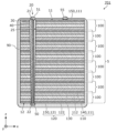
- FIG. 2 is a top view of the battery according to Embodiment 1.
- FIG. 3A is a cross-sectional view of an example of a battery cell included in the power generation element according to Embodiment 1.
- FIG. 3B is a cross-sectional view of another example of a battery cell included in the power generation element according to Embodiment 1.
- FIG. 3C is a cross-sectional view of another example of a battery cell included in the power generation element according to Embodiment 1.
- FIG. 4 is a cross-sectional view of the power generating element according to Embodiment 1.
- FIG. FIG. 5 is a cross-sectional view showing a usage example of the battery according to Embodiment 1.
- FIG. FIG. 6 is a cross-sectional view of a battery according to Embodiment 2.
- FIG. 7 is a cross-sectional view of a battery according to Embodiment 3.
- FIG. 8 is a cross-sectional view of a battery according to Embodiment 4.
- FIG. 9 is a cross-sectional view of a battery according to Embodiment 5.
- FIG. 10 is a cross-sectional view of a battery according to Embodiment 6.
- FIG. 11 is a cross-sectional view of a battery according to Embodiment 7.
- FIG. 12 is a top view of a battery according to Embodiment 7.
- FIG. 13 is a cross-sectional view of a battery according to another example of Embodiment 7.
- FIG. 14 is a cross-sectional view of a circuit board according to Embodiment 8.
- FIG. FIG. 15 is a flow chart showing Example 1 of the battery manufacturing method according to the embodiment.
- FIG. 16 is a flowchart illustrating Example 2 of the battery manufacturing method according to the embodiment.
- FIG. 17 is a flowchart showing Example 3 of the battery manufacturing method according to the embodiment.
- FIG. 18 is a flowchart illustrating Example 4 of the battery manufacturing method according to the embodiment.
- a battery according to an aspect of the present disclosure has at least one battery cell each including a structure in which a positive electrode layer, a negative electrode layer, and a solid electrolyte layer positioned between the positive electrode layer and the negative electrode layer are laminated.
- Each of the at least one battery cell having a power generation element is provided with a through hole penetrating in the stacking direction, and the cross-sectional area of the through hole in the direction perpendicular to the stacking direction in the positive electrode layer is equal to the negative electrode layer is larger than the cross-sectional area of the through-hole in the direction perpendicular to the stacking direction in , and the inner wall of the through-hole is inclined with respect to the stacking direction.
- the cross-sectional area of the positive electrode layer in the direction perpendicular to the stacking direction is larger than the cross-sectional area of the negative electrode layer in the direction perpendicular to the stacking direction. be able to. Therefore, deposition of metal derived from metal ions that have not been incorporated into the negative electrode layer can be suppressed, and the reliability and safety of the battery can be improved.
- the through-holes can provide a difference in area between the positive electrode layer and the negative electrode layer, there is no need to create a battery cell with a difference in area between the positive electrode layer and the negative electrode layer in advance. Therefore, for example, the thickness of each layer does not gradually increase or decrease at the coating start and end, and the battery cell can be formed by accurately determining the areas of the positive electrode layer, the negative electrode layer, and the solid electrolyte layer. This makes it possible to make the most of the capacity of the battery cells.
- a conductive member or the like for extracting current from the power generation element can be passed through the through hole, the area in plan view including the member for extracting current can be reduced. Therefore, the capacity density of the battery can be increased.
- the through hole of any one of the at least one battery cell is opened on each of the first main surface and the second main surface opposite to the first main surface of the power generation element. and the battery is electrically connected to the second main surface of the power generation element, and passes through the through hole from the opening position of the through hole on the second main surface to the through hole on the first main surface. It may further comprise a conductive member extending to the opening position of the.
- the electric potential of the second main surface of the power generation element can be guided to the first main surface side by the conductive member. That is, it is possible to take out the current of both the positive electrode and the negative electrode of the power generation element on the first main surface side.
- the mounting of the battery can be made compact.
- the pattern of connection terminals formed on the substrate can be made smaller. Therefore, a battery with excellent mountability can be realized.
- the conductive member passes through the inside of the power generating element, there is no need to form a structure necessary for extracting current on the side surface of the power generating element. Therefore, the size of the battery can be reduced, and the capacity density of the battery can be increased. For example, when mounting a battery on a substrate, it is possible to reduce the mounting area.
- the battery may further include an insulating member positioned between the conductive member and the inner wall of the through hole.
- the insulation between the conductive member and the battery cell is ensured inside the through hole, and the reliability of the battery can be improved.
- the insulating member may cover the inner wall of the through hole.
- the through-hole may have a truncated cone shape.
- the at least one battery cell may be a plurality of battery cells, and the plurality of battery cells may be stacked. Further, for example, at least some of the plurality of battery cells may be electrically connected in parallel and stacked. Further, for example, the plurality of battery cells may be electrically connected in series and stacked.
- the through-holes of the plurality of battery cells may have the same volume.
- the volume of each of the plurality of battery cells can be easily uniformed, and variations in capacity between the plurality of battery cells can be suppressed.
- the inner walls of the through-holes of the plurality of battery cells may form a continuous surface that is inclined with respect to the stacking direction.
- the through-holes of the plurality of battery cells may be continuous.
- some of the plurality of battery cells are stacked so that the through holes are connected to form a first cell stack, and other of the plurality of battery cells are stacked to form a first cell stack.
- a part of the cell stack is stacked so that the through holes are connected to form a second cell stack, and the through holes in the first cell stack and the through holes in the second cell stack are arranged in the stacking direction. The position may be different when viewed along the .
- the positions of the through-holes can be changed. For example, it is possible to avoid difficulty in forming an insulating member or the like in the through-hole due to an increase in the number of battery cells.
- a method for manufacturing a battery includes the steps of: forming a laminate in which a plurality of battery cells are laminated; and forming a through hole penetrating in the stacking direction in each of the plurality of battery cells. forming a conductive member that passes through the through-hole formed in each of the plurality of battery cells and penetrates each of the plurality of battery cells; and the through-hole formed in each of the plurality of battery cells.
- the step of forming the through hole includes cutting the through hole in a direction perpendicular to the stacking direction of the positive electrode layer
- the through-hole is formed so that the area is larger than the cross-sectional area of the through-hole in the direction perpendicular to the stacking direction in the negative electrode layer.
- this provides a battery including a conductive member that conducts the potential of one main surface of the laminate as described above to the other main surface, and an insulating member that insulates the conductive member from the battery cell within the through hole. can be formed.
- the step of forming the through holes may be performed after the step of forming the laminate.
- the laminate after the step of forming the through holes, the plurality of battery cells are laminated such that the through holes of the plurality of battery cells are connected, and the laminate may be followed by forming the insulating member and forming the conductive member.
- a through hole can be formed for each battery cell, increasing the degree of freedom in the shape of the formed through hole.
- the conductive member and the insulating member can be collectively formed in the through-holes of the stacked battery cells, the productivity of the battery is improved.
- the step of forming the through hole, the step of forming the insulating member, and the step of forming the conductive member may be performed before the step of forming the laminate.
- an insulating member and a conductive member can be formed for each through-hole of a plurality of battery cells, so that the insulating member and the conductive member can be formed easily and accurately.
- the step of forming the through hole and the step of forming the insulating member are performed before the step of forming the laminate, and the step of forming the conductive member is performed after the step of forming the laminate. may be performed.
- the insulating member As a result, it is possible to easily and accurately form the insulating member, which is required to be formed with high accuracy in order to improve the reliability of the battery.
- the conductive member can be collectively formed in the through-holes of the stacked battery cells, the productivity of the battery is improved.
- a circuit board includes at least one battery each including a structure in which a positive electrode layer, a negative electrode layer, and a solid electrolyte layer positioned between the positive electrode layer and the negative electrode layer are laminated.
- a power generation element having cells, a conductive member, and a circuit pattern layer laminated on the power generation element and having circuit wiring, and each of the at least one battery cell is provided with a through hole penetrating in the stacking direction.
- the cross-sectional area of the through-hole in the positive electrode layer in the direction perpendicular to the stacking direction is larger than the cross-sectional area of the through-hole in the negative electrode layer in the direction perpendicular to the stacking direction, and in the power generation element, the In each of the first main surface and the second main surface opposite to the first main surface of the power generation element, the through hole of any one of the at least one battery cell is open, and the conductive member is provided on the power generation element.
- the circuit pattern layer is electrically connected to part of the circuit wiring and is located on the first main surface side of the power generating element.
- a battery that achieves both high capacity density and high reliability as described above and a circuit board that includes a circuit pattern layer connected to the battery can be realized.
- the wiring board and the battery are integrated, it is possible to reduce the size and thickness of the electronic device.
- power can be directly supplied from the power generation element to a place where circuit wiring is required, it is possible to reduce wiring routing and suppress radiation noise from the wiring.
- each figure is a schematic diagram and is not necessarily strictly illustrated. Therefore, for example, scales and the like do not necessarily match in each drawing. Moreover, in each figure, substantially the same configurations are denoted by the same reference numerals, and overlapping descriptions are omitted or simplified.
- the x-axis, y-axis and z-axis indicate the three axes of a three-dimensional orthogonal coordinate system.
- the x-axis and the y-axis respectively correspond to the directions parallel to the first side of the rectangle and the second side orthogonal to the first side when the power generating element of the battery has a rectangular plan view shape.
- the z-axis coincides with the stacking direction of the plurality of battery cells and the layers of the battery cells included in the power generation element.
- the "stacking direction” corresponds to the direction normal to the main surfaces of the current collector and the active material layer.
- the term “plan view” means when viewed from a direction perpendicular to the main surface of the power generation element, unless otherwise specified, such as when the power generation element is used alone. It should be noted that the term “plan view of a certain surface”, such as “plan view of the first side surface”, refers to the “certain surface” viewed from the front.
- the terms “upper” and “lower” do not refer to the upward direction (vertically upward) and the downward direction (vertically downward) in absolute spatial recognition, but are based on the stacking order in the stacking structure. It is used as a term defined by a relative positional relationship. Also, the terms “above” and “below” are used not only when two components are spaced apart from each other and there is another component between the two components, but also when two components are spaced apart from each other. It also applies when two components are in contact with each other and are placed in close contact with each other. In the following description, the negative side of the z-axis is called “lower” or “lower”, and the positive side of the z-axis is called “upper” or “upper”.
- the expression “covering A” means covering at least part of “A”. That is, the expression “covering A” includes not only the case of “covering all of A” but also the case of “covering only a part of A.”
- “A” is, for example, the side surface and main surface of a given member such as a layer or terminal.
- ordinal numbers such as “first” and “second” do not mean the number or order of constituent elements unless otherwise specified. It is used for the purpose of distinguishing elements.
- Embodiment 1 The configuration of the battery according to Embodiment 1 will be described below.
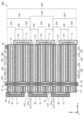
- FIG. 1 is a cross-sectional view of battery 1 according to the present embodiment.
- the battery 1 includes a power generating element 5 , an insulating member 30 , a conductive member 40 , a connecting member 50 , collector terminals 51 and 55 .
- the battery 1 is, for example, an all-solid battery.
- FIG. 2 is a top view of battery 1 according to the present embodiment. 1 shows a cross section taken along line II of FIG.
- the plan view shape of the power generation element 5 is, for example, rectangular as shown in FIG. That is, the shape of the power generation element 5 is a flat rectangular parallelepiped.
- flat means that the thickness (that is, the length in the z-axis direction) is shorter than each side (that is, each length in the x-axis direction and the y-axis direction) or the maximum width of the main surface.
- the plan view shape of the power generation element 5 may be a square, a hexagon, an octagon, or another polygon, or may be a circle, an ellipse, or the like.
- the thickness of each layer is exaggerated in order to facilitate understanding of the layer structure of the power generation element 5 .
- the power generation element 5 includes two main surfaces, a main surface 11 and a main surface 12, as shown in FIGS.
- both main surface 11 and main surface 12 are flat surfaces.
- the main surface 11 is an example of the first main surface.
- Main surface 12 is an example of a second main surface.
- the major surface 11 and the major surface 12 are facing each other and parallel to each other.
- the main surface 11 is the top surface of the power generation element 5 .
- the main surface 12 is the surface opposite to the main surface 11 and is the bottom surface of the power generating element 5 .
- Main surface 11 and main surface 12 each have, for example, a larger area than the side surface of power generation element 5 .
- the side faces of the power generating element 5 include two sets of two parallel side faces facing each other.
- the side surface of the power generation element 5 is, for example, a flat surface.
- the side surface of the power generation element 5 is, for example, a cut surface formed by collectively cutting a stack of a plurality of battery cells 100 . By aligning the cutting direction with the stacking direction, a plurality of battery cells 100 having the same size can be formed.
- the power generation element 5 has multiple battery cells 100 .
- the battery cell 100 is a battery with a minimum configuration and is also called a unit cell.
- a plurality of battery cells 100 are electrically connected in series and stacked.
- all the battery cells 100 included in the power generation element 5 are electrically connected in series.
- a battery 1 is a laminated battery in which a plurality of battery cells 100 are integrated by adhesion, bonding, or the like.
- the number of battery cells 100 included in the power generation element 5 is eight, but the number is not limited to this.
- the number of battery cells 100 included in the power generation element 5 may be an even number such as two or four, or an odd number such as three or five.
- Each of the plurality of battery cells 100 is provided with a through-hole 20 that penetrates each battery cell 100 in the stacking direction.
- the through holes 20 of the plurality of battery cells 100 are collectively formed, for example, by drilling holes penetrating the power generating elements 5 in the stacking direction.
- Each of the plurality of battery cells 100 includes a positive electrode layer 110, a negative electrode layer 120, and a solid electrolyte layer 130.
- the positive electrode layer 110 has a positive electrode current collector 111 and a positive electrode active material layer 112 .
- the negative electrode layer 120 has a negative electrode current collector 121 and a negative electrode active material layer 122 .
- a positive electrode current collector 111, a positive electrode active material layer 112, a solid electrolyte layer 130, a negative electrode active material layer 122, and a negative electrode current collector 121 are stacked in this order along the z-axis. .
- the positive electrode current collector 111, the positive electrode active material layer 112, the solid electrolyte layer 130, the negative electrode active material layer 122, and the negative electrode current collector 121 each extend in a direction perpendicular to the z-axis direction (that is, the x-axis direction and y-axis direction).
- the configurations of the plurality of battery cells 100 are, for example, substantially the same.
- the plurality of battery cells 100 are stacked along the z-axis such that the layers forming the battery cells 100 are arranged in the same order. Thereby, the plurality of battery cells 100 are electrically connected in series and stacked.
- the plurality of battery cells 100 have, for example, the same size. As a result, the operation states of the plurality of battery cells 100 can be easily aligned, and the battery 1 can achieve both high capacity density and high reliability.
- main surface 11 constitutes part of positive electrode layer 110 of battery cell 100 positioned at the top. Specifically, main surface 11 is the upper main surface of positive electrode layer 110 of battery cell 100 positioned at the top.
- main surface 12 constitutes part of the negative electrode layer 120 of the battery cell 100 positioned at the bottom.
- main surface 12 is the lower main surface of negative electrode layer 120 of battery cell 100 positioned at the bottom.
- two battery cells 100 adjacent in the stacking direction share a current collector. That is, one positive electrode current collector 111 of the two battery cells 100 and the other negative electrode current collector 121 of the two battery cells 100 constitute one intermediate layer current collector 140 .
- the positive electrode active material layer 112 is laminated on the lower surface of the intermediate layer current collector 140 .
- a negative electrode active material layer 122 is laminated on the upper surface of the intermediate current collector 140 .
- Interlayer current collector 140 is also referred to as a bipolar current collector.
- the end layer current collectors 150 shown in FIG. 1 are positioned at both ends of the power generation element 5 in the stacking direction.
- a positive electrode active material layer 112 is arranged on the lower surface of the positive electrode current collector 111 .
- the end layer current collector 150 located at the lower end, which is the other end in the stacking direction, is the negative electrode current collector 121 .
- a negative electrode active material layer 122 is arranged on the upper surface of the negative electrode current collector 121 .
- FIG. 3A is a cross-sectional view of battery cell 100 included in power generation element 5 according to the present embodiment.
- the positive electrode current collector 111 and the negative electrode current collector 121 shown in FIG. 3A are the intermediate layer current collector 140 or the end layer current collector 150 shown in FIG. 1, respectively.
- the positive electrode current collector 111 and the negative electrode current collector 121 are conductive foil-like, plate-like, or mesh-like members, respectively.
- the positive electrode current collector 111 and the negative electrode current collector 121 may each be, for example, a conductive thin film. Examples of materials that constitute the positive electrode current collector 111 and the negative electrode current collector 121 include metals such as stainless steel (SUS), aluminum (Al), copper (Cu), and nickel (Ni).
- the positive electrode current collector 111 and the negative electrode current collector 121 may be formed using different materials.
- each of the positive electrode current collector 111 and the negative electrode current collector 121 is, for example, 5 ⁇ m or more and 100 ⁇ m or less, but is not limited to this.
- a cathode active material layer 112 is in contact with the main surface of the cathode current collector 111 .
- the positive electrode current collector 111 may include a current collector layer which is a layer containing a conductive material and provided in a portion in contact with the positive electrode active material layer 112 .
- a negative electrode active material layer 122 is in contact with the main surface of the negative electrode current collector 121 .
- the negative electrode current collector 121 may include a current collector layer which is a layer containing a conductive material and provided in a portion in contact with the negative electrode active material layer 122 .
- intermediate layer current collector 140 and the end layer current collector 150 may have the same thickness and material. Different current collectors, such as thickness and material, may be used.
- the positive electrode active material layer 112 is arranged on the main surface of the positive electrode current collector 111 on the negative electrode layer 120 side.
- the positive electrode active material layer 112 is a layer containing a positive electrode material such as an active material.
- the positive electrode active material layer 112 contains, for example, a positive electrode active material.
- Examples of the positive electrode active material contained in the positive electrode active material layer 112 include lithium cobaltate composite oxide (LCO), lithium nickelate composite oxide (LNO), lithium manganate composite oxide (LMO), and lithium-manganese.
- - Positive electrode active materials such as nickel composite oxide (LMNO), lithium-manganese-cobalt composite oxide (LMCO), lithium-nickel-cobalt composite oxide (LNCO), lithium-nickel-manganese-cobalt composite oxide (LNMCO) substances can be used.
- Various materials capable of withdrawing and inserting ions such as Li or Mg can be used as the material of the positive electrode active material.
- a solid electrolyte such as an inorganic solid electrolyte may be used.
- a sulfide solid electrolyte, an oxide solid electrolyte, or the like can be used as the inorganic solid electrolyte.
- a sulfide solid electrolyte for example, a mixture of Li2S and P2S5 can be used.
- the surface of the positive electrode active material may be coated with a solid electrolyte.
- a conductive material such as acetylene black or a binding binder such as polyvinylidene fluoride may be used.
- the positive electrode active material layer 112 is produced by coating the main surface of the positive electrode current collector 111 with a paste-like paint in which the material contained in the positive electrode active material layer 112 is kneaded together with a solvent and drying it.
- the positive electrode layer 110 also referred to as a positive electrode plate
- the thickness of the positive electrode active material layer 112 is, for example, 5 ⁇ m or more and 300 ⁇ m or less, but is not limited thereto.
- the negative electrode active material layer 122 is arranged on the main surface of the negative electrode current collector 121 on the positive electrode layer 110 side.
- the negative electrode active material layer 122 is arranged to face the positive electrode active material layer 112 .
- the negative electrode active material layer 122 is a layer containing, for example, a negative electrode material such as an active material.
- the negative electrode material is a material that constitutes the counter electrode of the positive electrode material.
- the negative electrode active material layer 122 contains, for example, a negative electrode active material.
- a negative electrode active material contained in the negative electrode active material layer 122 for example, a negative electrode active material such as graphite or metallic lithium can be used.
- Various materials capable of extracting and inserting ions such as lithium (Li) or magnesium (Mg) may be used as materials of the negative electrode active material.
- a solid electrolyte such as an inorganic solid electrolyte may be used.
- an inorganic solid electrolyte for example, a sulfide solid electrolyte or an oxide solid electrolyte can be used.
- a sulfide solid electrolyte for example, a mixture of lithium sulfide (Li 2 S) and phosphorus pentasulfide (P 2 S 5 ) can be used.
- a conductive material such as acetylene black, or a binding binder such as polyvinylidene fluoride may be used.
- the negative electrode active material layer 122 is produced by coating the main surface of the negative electrode current collector 121 with a paste-like paint in which the material contained in the negative electrode active material layer 122 is kneaded together with a solvent and drying it.
- the negative electrode layer 120 also referred to as a negative electrode plate
- the thickness of the negative electrode active material layer 122 is, for example, 5 ⁇ m or more and 300 ⁇ m or less, but is not limited thereto.
- the solid electrolyte layer 130 is arranged between the positive electrode active material layer 112 and the negative electrode active material layer 122 . Solid electrolyte layer 130 is in contact with each of positive electrode active material layer 112 and negative electrode active material layer 122 .
- Solid electrolyte layer 130 is a layer containing an electrolyte material. As the electrolyte material, generally known battery electrolytes can be used. The thickness of solid electrolyte layer 130 may be 5 ⁇ m or more and 300 ⁇ m or less, or may be 5 ⁇ m or more and 100 ⁇ m or less.
- Solid electrolyte layer 130 contains a solid electrolyte.
- the solid electrolyte has, for example, lithium ion conductivity.
- a solid electrolyte such as an inorganic solid electrolyte can be used.
- a sulfide solid electrolyte, an oxide solid electrolyte, or the like can be used as the inorganic solid electrolyte.
- a sulfide solid electrolyte for example, a mixture of Li2S and P2S5 can be used.
- the solid electrolyte layer 130 may contain a binding binder such as polyvinylidene fluoride.
- the positive electrode active material layer 112, the negative electrode active material layer 122, and the solid electrolyte layer 130 are maintained in the form of parallel plates. As a result, it is possible to suppress the occurrence of cracks or collapse due to bending. Note that the positive electrode active material layer 112, the negative electrode active material layer 122, and the solid electrolyte layer 130 may be combined and smoothly curved.
- the end face of the positive electrode current collector 111 and the end face of the negative electrode current collector 121 match when viewed from the z-axis direction.
- positive electrode current collector 111 positive electrode active material layer 112, solid electrolyte layer 130, negative electrode active material layer 122, and negative electrode current collector 121 have the same shape and size. , the contours of each match. That is, the shape of the battery cell 100 is a flat rectangular parallelepiped plate shape.
- the intermediate layer current collector 140 is shared by the plurality of battery cells 100 as shown in FIG.
- Such a power generation element 5 is formed by combining and stacking not only the battery cell 100 shown in FIG. 3A but also the battery cells 100B and 100C shown in FIGS. 3B and 3C.
- the battery cell 100 shown in FIG. 3A will be described as a battery cell 100A.
- a battery cell 100B shown in FIG. 3B has a configuration in which the positive electrode current collector 111 is removed from the battery cell 100A shown in FIG. 3A. That is, the positive electrode layer 110B of the battery cell 100B is composed of the positive electrode active material layer 112 only.
- a battery cell 100C shown in FIG. 3C has a configuration in which the negative electrode current collector 121 is removed from the battery cell 100A shown in FIG. 3A. That is, the negative electrode layer 120C of the battery cell 100C consists of the negative electrode active material layer 122 only.
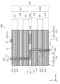
- FIG. 4 is a cross-sectional view showing the power generating element 5 according to this embodiment.
- FIG. 4 is a diagram showing a state before only the power generation element 5 of FIG. 1 is extracted and the through holes 20 are formed in the plurality of battery cells 100 .
- the battery cell 100A is arranged in the bottom layer, and a plurality of battery cells 100C are sequentially stacked upward in the same direction. Thereby, the power generation element 5 is formed.
- the method of forming the power generation element 5 is not limited to this.
- the battery cell 100A may be arranged in the uppermost layer.
- the battery cell 100A may be arranged at a position different from both the top layer and the bottom layer.
- a plurality of battery cells 100A may be used.
- a unit of two battery cells 100 sharing a current collector may be formed by coating both sides of one current collector, and the formed units may be stacked.
- all battery cells 100 are connected in series, and no battery cells connected in parallel are included. Therefore, a high-voltage battery 1 can be realized.
- a through-hole 20 is provided in each of the plurality of battery cells 100 .
- the through hole 20 penetrates from one main surface of the battery cell 100 to the other main surface.
- Through hole 20 extends from one main surface of battery cell 100 to the other main surface through positive electrode layer 110 , solid electrolyte layer 130 and negative electrode layer 120 .
- the cross-sectional area of the through-hole 20 in the direction perpendicular to the stacking direction in the positive electrode layer 110 is the cross-sectional area of the through-hole 20 in the direction perpendicular to the stacking direction in the negative electrode layer 120. larger than area.
- the direction perpendicular to the stacking direction is the extending direction of each layer.
- the width of the through-hole 20 in the positive electrode layer 110 is larger than the width of the through-hole 20 in the negative electrode layer 120 in a cross-sectional view.
- the through holes 20 of the plurality of battery cells 100 are continuous. Thereby, each through-hole 20 of the plurality of battery cells 100 forms one through-hole that penetrates the power generation element 5 in the stacking direction. This makes it easier to form the conductive member 40 and the like extending through the through hole 20 .
- the through hole 20 of the battery cell 100 positioned at the top is open on the main surface 11 .
- the opening position 21 of the through hole 20 of the battery cell 100 positioned at the top is positioned on the main surface 11 .
- the through hole 20 of the battery cell 100 positioned at the bottom is open on the main surface 12 . That is, the opening position 22 of the through hole 20 of the battery cell 100 positioned at the bottom is positioned on the main surface 12 .
- the positive electrode layer 110 is arranged on the main surface 11 side, and the negative electrode layer 120 is arranged on the main surface 12 side.
- the through hole 20 has a shape in which the cross-sectional area on the main surface 12 side in the stacking direction is narrow. Therefore, the opening area of through-hole 20 on main surface 11 is larger than the opening area of through-hole 20 on main surface 12 .
- the collector terminal 51 is positioned inside the through hole 20 in plan view with respect to the main surface 11, as will be described later. By increasing the opening area of the through hole 20 in the main surface 11 , it becomes easier to form the collector terminal 51 provided on the main surface 11 side.
- each through-hole 20 of the plurality of battery cells 100 is inclined with respect to the stacking direction. That is, each through-hole 20 of the plurality of battery cells 100 has a tapered inner wall 25 . This makes it possible to easily provide a difference in the cross-sectional area of the through hole 20 between the positive electrode layer 110 and the negative electrode layer 120 .
- the inner wall 25 is the inner side surface of the battery cell 100 forming the through hole 20 . In this embodiment, the entire surface of the inner wall 25 is inclined with respect to the stacking direction. Note that the inner wall 25 may have a portion that is not inclined with respect to the stacking direction.
- the inner wall 25 is composed of inner surfaces of the positive electrode layer 110 , the solid electrolyte layer 130 and the negative electrode layer 120 , for example.
- each through-hole 20 of the plurality of battery cells 100 has, for example, a truncated cone shape.
- the inner wall 25 of the through hole 20 is not formed with a corner, and electric field concentration inside the through hole 20 can be suppressed.
- the through hole 20 can be easily formed by a drill having a taper angle or the like. Note that.
- the shape of the through hole 20 is not limited to the truncated cone shape, and may be another shape such as a truncated pyramid shape such as a truncated square pyramid shape or a truncated hexagonal pyramid shape.
- the inner wall 25 of each through-hole 20 of the plurality of battery cells 100 forms one continuous surface that is inclined with respect to the stacking direction. Therefore, the through-holes 20 of the plurality of battery cells 100 are continuous to penetrate the power generation element 5 along the stacking direction to form one elongated truncated cone-shaped through-hole. Since the inner walls 25 of the through-holes 20 of the plurality of battery cells 100 are continuous in this way, it is difficult for the inner walls 25 to have easily damaged portions, and the inner walls 25 are less likely to cause the material of the battery cells 100 to collapse. Become. Also, in forming the insulating member 30 and the conductive member 40 , it becomes easier to insert the material into the through hole 20 .
- the direction in which the through holes 20 of the plurality of battery cells 100 are connected may be inclined with respect to the stacking direction.
- the insulating member 30 is arranged inside the through hole 20 .
- the insulating member 30 is positioned between the conductive member 40 and the inner wall 25 of the through hole 20 .
- the insulation member 30 can ensure insulation between the conductive member 40 and the inner surfaces of the plurality of battery cells 100 , which are the inner walls 25 of the through holes 20 .
- the insulating member 30 is arranged along the inner wall 25 of the through hole 20 .
- the insulating member 30 collectively covers the inner walls 25 of the through holes 20 of the plurality of battery cells 100 and is in contact with the inner walls 25 of the through holes 20 of the plurality of battery cells 100 . Thereby, collapse of the material of each layer of the battery cell 100 can be suppressed at the inner wall 25 of the through-hole 20 , and short-circuiting between the positive electrode layer 110 and the negative electrode layer 120 can be suppressed.
- the insulating member 30 covers the entire surface of the inner walls 25 of the through holes 20 of the plurality of battery cells 100 . A gap may be provided in a part between the insulating member 30 and the inner wall 25 .
- the insulating member 30 surrounds the outer periphery of the conductive member 40 when viewed from the stacking direction and is in contact with the conductive member 40 .
- the conductive member 40 is columnar, and the insulating member 30 covers the entire side surface of the columnar conductive member 40 and is in contact with the side surface of the conductive member 40 .
- a gap may be provided in a part between the insulating member 30 and the conductive member 40 .
- the insulating member 30 is filled so as to fill the through holes 20 of the plurality of battery cells 100 together with the conductive member 40 .
- the insulating member 30 for example, completely fills the space between the inner wall 25 of each through-hole 20 of the plurality of battery cells 100 and the conductive member 40 . Therefore, the insulating member 30 has a shape in which the through holes 20 of the plurality of battery cells 100 are connected, except that a through hole through which the conductive member 40 penetrates is formed in the center when viewed in the stacking direction. are the same.
- the shape of the insulating member 30 is, for example, a tubular shape with a circular or polygonal outer periphery.
- the shape of the insulating member 30 is not limited to such a shape, and the insulating member 30 is formed to match the shapes of the through hole 20 and the conductive member 40, for example.
- the thickness of the insulating member 30 increases from the end of the insulating member 30 on the main surface 12 side toward the end of the insulating member 30 on the main surface 11 side. Since the plurality of battery cells 100 are connected in series and stacked, the conductive member 40 electrically connected to the main surface 12 through the through hole 20 and the battery cell at the corresponding position move closer to the main surface 11 . The potential difference with 100 increases. Therefore, the thickness of the insulating member 30 increases in a region where the potential difference between the conductive member 40 and the battery cell 100, that is, the voltage at which the insulating member 30 provides insulation increases. As a result, the insulation reliability is improved, and the reliability of the battery 1 can be improved. In this embodiment, the thickness of insulating member 30 is equal to the distance between conductive member 40 and inner wall 25 . Details of the conductive member 40 will be described later.
- the insulating member 30 is formed using an insulating material that is electrically insulating.
- the insulating member 30 contains resin.
- the resin is, for example, an epoxy resin, but is not limited to this.
- An inorganic material may be used as the insulating material.
- Usable insulating materials are selected based on various properties such as flexibility, gas barrier properties, impact resistance, and heat resistance.
- the insulating member 30 is formed, for example, by filling the through hole 20 with an insulating material, molding the insulating material into the shape of the through hole 20, or coating the inner wall 25 with the insulating material.
- the conductive member 40 is arranged inside the through hole 20 .
- the conductive member 40 is electrically connected to the main surface 12 of the power generating element 5 via the connecting member 50 . Therefore, the conductive member 40 is electrically connected to the end layer current collector 150 in the negative electrode layer 120 of the lowermost battery cell 100 , that is, to the negative electrode current collector 121 .
- the conductive member 40 extends from the opening position 22 of the through hole 20 on the main surface 12 to the opening position 21 of the through hole 20 on the main surface 11 through the through holes 20 of the plurality of battery cells 100 .
- the conductive member 40 penetrates from the main surface 11 to the main surface 12 of the power generation element 5 through the through holes 20 of the plurality of battery cells 100 .
- the potential of the negative electrode layer 120 of the lowermost battery cell 100 is guided to the main surface 11 side, and current can be extracted from the lowermost battery cell 100 on the main surface 11 side of the power generation element 5.
- the conductive member 40 functions as a through electrode penetrating the power generation element 5 . Therefore, in the battery 1, both the positive and negative potentials of the entire power generating element 5 connected in series on the main surface 11 side can be provided.
- the end of the conductive member 40 on the main surface 11 side is in contact with the collector terminal 51 .
- An end portion of the conductive member 40 on the main surface 12 side is in contact with the connecting member 50 .
- An insulating member 30 is arranged between the conductive member 40 and the inner wall 25 .
- the conductive member 40 is formed on the inner wall 25 of the through-hole 20 of each of the plurality of battery cells 100, the positive electrode active material layer 112, the solid electrolyte layer 130, the negative electrode active material layer 122, the intermediate layer current collector 140, and the upper end layer. It is not in contact with the current collector 150 . That is, the conductive member 40 extends from the opening position 22 to the opening position 21 while maintaining insulation from the plurality of battery cells 100 within the through hole 20 .
- the conductive member 40 has, for example, a columnar shape, but may have another shape such as a prismatic shape.
- the thickness of the conductive member 40 is constant, for example.
- the conductive member 40 is formed using a conductive resin material or the like.
- the conductive resin material includes, for example, metal particles and resin.
- the conductive member 40 may be formed using a metal material such as aluminum, copper, nickel, stainless steel, or solder. Conductive materials that can be used are selected based on various properties such as flexibility, gas barrier properties, impact resistance, heat resistance, and solder wettability.
- the conductive member 40 can be formed by methods such as printing, plating, and molding, for example.
- connection member 50 is arranged on the main surface 12 side of the power generation element 5 .
- the connecting member 50 is connected to the conductive member 40 at the opening location 22 .
- the connecting member 50 covers the main surface 12 near the opening position 22 and is also connected to the main surface 12 .
- the connection member 50 electrically connects the conductive member 40 and the main surface 12, that is, the negative electrode layer 120 of the battery cell 100 positioned at the bottom.
- connection member 50 is formed using a conductive material.
- the connection member 50 is formed using metal materials such as aluminum, copper, nickel, stainless steel, and solder.
- the connection member 50 may be formed using a conductive resin material or the like.
- the connection member 50 can be formed by, for example, printing, plating, soldering, or the like.
- the connection member 50 may be formed by connecting the conductive member 40 to the outside of the main surface 12 through the through hole 20 and connecting it to the main surface 12 . In other words, the connecting member 50 may be part of the conductive member 40 .
- the collector terminal 51 is arranged on the main surface 11 side of the power generation element 5 .
- the collector terminal 51 is connected to the conductive member 40 at the opening position 21 .
- the collector terminal 51 is electrically connected to the negative electrode layer 120 of the battery cell 100 positioned at the bottom via the conductive member 40 and the connecting member 50 .
- the current collecting terminal 51 is one of the external connection terminals of the battery 1, and in this embodiment, it is a negative electrode extraction terminal.
- a portion of the collector terminal 51 is in contact with the insulating member 30 . Note that the collector terminal 51 does not have to be in contact with the insulating member 30 .
- the collector terminal 51 may be connected to the conductive member 40 via another conductive connection layer or the like.
- the collector terminal 51 is positioned inside the through-hole 20, in the present embodiment, inside the outer circumference of the insulating member 30 in a plan view with respect to the main surface 11. As shown in FIG. Therefore, the collector terminal 51 is not in contact with the main surface 11 and is insulated from the main surface 11, that is, the positive electrode layer 110 of the battery cell 100 positioned at the top.
- the collector terminal 55 is arranged on the main surface 11 side of the power generation element 5 . Therefore, the collector terminal 51 and the collector terminal 55 are provided on the same main surface 11 side of the power generating element 5 .
- the collector terminal 55 is arranged on the main surface 11 and connected to the main surface 11 . That is, the current collector terminal 55 is electrically connected to the end layer current collector 150 in the positive electrode layer 110 of the uppermost battery cell 100 , ie, the positive electrode current collector 111 .
- the current collecting terminal 55 is one of the external connection terminals of the battery 1, and is a positive electrode extraction terminal in the present embodiment. Note that the collector terminal 55 may be connected to the main surface 11 via another conductive connection layer or the like.
- the collector terminals 51 and 55 are arranged along the x-axis direction, for example.
- the positional relationship between the collector terminal 51 and the collector terminal 55 in plan view is not particularly limited, and is designed according to, for example, the wiring pattern of the board on which the battery 1 is mounted.
- the collector terminal 51 and the collector terminal 55 are protruding terminals provided on the main surface 11 side of the power generating element 5, respectively, but the shape of the collector terminal 51 and the collector terminal 55 is not particularly limited.
- the collector terminal 51 and the collector terminal 55 may extend in a plate shape along the main surface 11 after necessary insulation is performed.
- the collector terminal 51 and the collector terminal 55 are each formed using a material having conductivity.
- the collector terminal 51 and the collector terminal 55 are each formed using a metal material such as aluminum, copper, nickel, stainless steel, or solder.
- each of the current collector terminal 51 and the current collector terminal 55 may be formed using a conductive resin material or the like.
- the collector terminals 51 and the collector terminals 55 can be formed by, for example, printing, plating, soldering, or the like.
- the current collecting terminal 51 may be formed by projecting the conductive member 40 from the through hole 20 to the outside of the main surface 11 . That is, the collector terminal 51 may be part of the conductive member 40 .
- FIG. 5 is a cross-sectional view showing a usage example of the battery 1. As shown in FIG. FIG. 5 shows the battery 1 mounted on the circuit board 190 in the upside down state of the battery 1 shown in FIG.
- a circuit board 190 for mounting the battery 1 has an insulating plate-like substrate 191 and circuit wiring 192 .
- the circuit wiring 192 is a circuit pattern formed on the substrate 191 .
- the collector terminal 51 of the battery 1 is connected to part of the circuit wiring 192 .
- the collector terminal 55 of the battery 1 is connected to another part of the circuit wiring 192 .
- power from the battery 1 is supplied to the electronic device 195 mounted on the circuit board 190 and connected to the circuit wiring 192 .
- the battery 1 In the battery 1 , current collecting terminals 51 and 55 that are terminals for taking out the positive electrode and the negative electrode are provided on the same main surface 11 . Since the collector terminal 51 and the collector terminal 55 are arranged inside the outer periphery of the power generation element 5 in a plan view, the battery 1 can be mounted on the circuit board 190 with a minimum mounting area and low height.
- the collector terminal 51 and the collector terminal 55 are provided on the main surface 11, the wiring length of the circuit wiring 192 can be easily shortened, and the wiring resistance and the noise caused by the current flowing through the wiring can be reduced. can be reduced.
- circuit board 190 may be mounted with a battery according to each embodiment described later.
- the battery 1 since the plurality of battery cells 100 are connected in series and stacked, the battery 1 with high capacity density and high voltage can be realized.
- a through hole 20 is provided in each of the plurality of battery cells 100 .
- the cross-sectional area of through-hole 20 in the direction perpendicular to the stacking direction in positive electrode layer 110 is larger than the cross-sectional area of through-hole 20 in the direction perpendicular to the stacking direction in negative electrode layer 120 .
- the through holes 20 can reduce the area of the positive electrode layer 110 compared to the negative electrode layer 120 . Therefore, deposition of metal derived from metal ions that have not been taken into the negative electrode layer 120 can be suppressed, and the reliability and safety of the battery 1 can be improved.
- the battery 1 is mounted on a substrate or the like as described above, the battery 1 is replaced infrequently or not in many cases. The significance of sexual improvement is great.
- the battery 1 since the area difference between the positive electrode layer 110 and the negative electrode layer 120 can be realized by the through hole 20, it is necessary to form the battery cell 100 with the area difference between the positive electrode layer 110 and the negative electrode layer 120 in advance. None. Therefore, in the battery 1, for example, by collectively cutting a plurality of stacked battery cells 100, the power generating element 5 having flat side surfaces can be formed. By using batch cutting, for example, the areas of the positive electrode layer 110, the negative electrode layer 120, and the solid electrolyte layer 130 are accurately determined without gradual increase or decrease in film thickness at the coating start and end of each layer. Thereby, the capacity of the battery cell 100 can be utilized to the maximum, and the capacity density of the battery 1 can be increased. In addition, since the capacity variation among the plurality of battery cells 100 is reduced, the accuracy of the battery capacity can be improved.
- the electric potential of the main surface 12 of the power generation element 5, that is, the negative electrode layer 120 of the battery cell 100 located at the bottom, can be led to the main surface 11 side by the conductive member 40 passing through the through hole 20. That is, it is possible to take out the current of both the positive electrode and the negative electrode of the power generation element 5 on the main surface 11 side.
- the mounting of the battery 1 can be made compact.
- the pattern (also referred to as footprint) of connection terminals formed on the substrate can be reduced.
- mounting can be performed in a state in which the main surface 11 of the battery 1 and the substrate are arranged in parallel, so that low-height mounting on the substrate can be realized. Reflow solder connection or the like can be used for mounting. In this way, the battery 1 with excellent mountability can be realized.
- the battery 1 can be miniaturized and the capacity density of the battery 1 can be increased. For example, when mounting the battery 1 on a substrate, it is possible to reduce the mounting area.
- Embodiment 2 Next, Embodiment 2 will be described. The following description focuses on the differences from the first embodiment, and omits or simplifies the description of the common points.
- FIG. 6 is a cross-sectional view of battery 201 according to the present embodiment. As shown in FIG. 6 , battery 201 differs from battery 1 according to Embodiment 1 in that side insulating layer 60 is further provided.
- the side insulating layer 60 covers the side surface of the power generation element 5 .
- the lateral insulation layer 60 covers all sides of the power generation element 5, for example.
- the side insulating layer 60 may cover the respective ends of the main surface 11 and the main surface 12 . As a result, peeling of the end layer current collectors 150 arranged on the main surfaces 11 and 12 can be suppressed, and the reliability of the battery 201 can be further improved.
- the side insulating layer 60 is formed using an electrically insulating insulating material.
- the side insulating layer 60 contains resin.
- the resin is, for example, an epoxy resin, but is not limited to this.
- An inorganic material may be used as the insulating material.
- Usable insulating materials are selected based on various properties such as flexibility, gas barrier properties, impact resistance, and heat resistance.
- side insulating layer 60 may be provided in a battery according to each embodiment described later.
- Embodiment 3 Next, Embodiment 3 will be described. The following description focuses on the differences from the first and second embodiments, and omits or simplifies the description of the common points.
- FIG. 7 is a cross-sectional view of battery 301 according to the present embodiment.
- battery 301 differs from battery 1 according to Embodiment 1 in that battery cell 100 is provided with through hole 320 instead of battery cell 100 with through hole 20 . differ.
- a through hole 320 is provided in each of the plurality of battery cells 100 .
- the cross-sectional area of the through-hole 320 in the direction perpendicular to the stacking direction of the positive electrode layer 110 is the cross-sectional area of the through-hole 320 in the direction perpendicular to the stacking direction of the negative electrode layer 120. larger than area.
- the through holes 320 of the plurality of battery cells 100 have substantially the same volume and shape.
- the inner walls 325 of the through-holes 320 of the plurality of battery cells 100 are inclined at the same angle with respect to the stacking direction.
- the cross-sectional areas of the through-holes 320 in the direction perpendicular to the stacking direction in the positive electrode layers 110 of the plurality of battery cells 100 are substantially the same.
- the cross-sectional area of the through-holes 320 in the direction perpendicular to the stacking direction in the negative electrode layers 120 of the plurality of battery cells 100 is substantially the same.
- the through-holes 320 are formed in each of the plurality of battery cells 100, the volume of the through-holes 320 is the same, so the volumes of the plurality of battery cells 100 are easily uniform, and the capacity variation among the plurality of battery cells 100 is suppressed. can. Therefore, in the charging and discharging of the battery 301, the operating voltage of the plurality of battery cells 100 connected in series and stacked can be easily made uniform, and the occurrence of overcharge or overdischarge in a specific battery cell 100 can be suppressed. Therefore, reliability of the battery 301 can be improved. In particular, in the case of a battery with a small size and a small area, it is effective for the through holes 320 to have the same volume because the effect of the volume of the through holes 320 is large.
- the inner walls 25 of the through holes 20 of the plurality of battery cells 100 form one continuous surface that is inclined with respect to the stacking direction.
- the inner walls 325 of the through-holes 320 of the plurality of battery cells 100 are discontinuous and have a zigzag shape.
- the through holes 320 of the plurality of battery cells 100 are connected to form one through hole penetrating the power generating element 5 in the stacking direction. Also, the insulating member 30 and the conductive member 40 are arranged in the through hole 320 . As a result, the battery 301 with high capacity density, high reliability, and mountability like the battery 1 can be realized.
- Embodiment 4 Next, Embodiment 4 will be described. The following description focuses on the differences from the first to third embodiments, and omits or simplifies the description of the common points.
- FIG. 8 is a cross-sectional view of battery 401 according to the present embodiment.
- battery 401 differs from battery 301 according to Embodiment 3 in that power generation element 405 is provided instead of power generation element 5 .
- Battery 401 also differs from battery 301 according to the third embodiment in that it further includes positive electrode insulating layer 71 , negative electrode insulating layer 72 , negative electrode connection portion 81 , and positive electrode connection portion 82 .
- the power generation element 405 includes multiple battery cells 100 . Some of the plurality of battery cells 100 are electrically connected in parallel and stacked. Power generation element 405 includes both parallel and series connections of battery cells 100 .
- the power generation element 405 includes multiple parallel laminates 407 .
- each of the multiple parallel stacks 407 includes an odd number of battery cells 100, specifically three.
- the odd number of battery cells 100 included in parallel stack 407 are electrically connected in parallel.
- a parallel connection is made by a negative electrode connection portion 81 and a positive electrode connection portion 82 .
- a plurality of parallel laminates 407 are electrically connected in series. The series connection is achieved by stacking the parallel stacks 407 in the stacking direction of the battery cells 100 (that is, the z-axis direction). Specific connections will be described later.
- the number of parallel stacks 407 included in power generation element 405 and the number of battery cells 100 included in parallel stacks 407 are not particularly limited, and may be an odd number or an even number. . Moreover, a stack in which a plurality of battery cells 100 are connected in series may be connected in parallel.
- the power generation element 405 includes side surfaces 13 and 14 . Sides 13 and 14 face away from each other and are parallel to each other. Sides 13 and 14 are each flat surfaces.
- the side surface 13 of the power generation element 405 is formed by connecting the first side surfaces of the plurality of parallel laminates 407 flush with each other.
- the side surface 14 of the power generation element 405 is formed by connecting the second side surfaces of the plurality of parallel laminates 407 flush with each other.
- a large capacity is realized by forming a parallel laminate 407 in which a plurality of battery cells 100 are connected in parallel and laminated. Furthermore, a high voltage is realized by connecting a plurality of parallel laminates 407 in series.
- the layers constituting the battery cells 100 are arranged in reverse order. That is, the plurality of battery cells 100 are stacked side by side along the z-axis while the order of the layers constituting the battery cells 100 alternates.
- the bottom layer and the top layer of parallel stack 407 are current collectors of different polarities, respectively.
- the lowermost layer is the negative electrode current collector 121 of the negative electrode layer 120
- the uppermost layer is the positive electrode current collector 111 of the positive electrode layer 110 .
- Each of the three parallel stacks 407 has the same configuration.
- serial connection can be easily performed by stacking a plurality of parallel stacked bodies 407 in the z-axis direction.
- two parallel laminates 407 can be directly laminated such that current collectors of opposite polarities face each other.
- no insulating layer is arranged between parallel stacked bodies 407 adjacent in the stacking direction. More specifically, in two parallel stacked bodies 407 adjacent to each other, the uppermost positive electrode layer 110 of the lower parallel stacked body 407 and the lowermost negative electrode layer 120 of the upper parallel stacked body 407 share a cell.
- the intermediate layer current collector 141 shown in FIG. 8 is a current collector shared by two parallel laminates 407 .
- the intermediate layer current collector 141 functions as the positive electrode current collector 111 of one parallel laminate 407 and functions as the negative electrode current collector 121 of the other parallel laminate 407 .
- the positive electrode active material layer 112 is arranged on the lower surface of the intermediate current collector 141, and the negative electrode active material layer 122 is arranged on the upper surface.
- each parallel laminate 407 in two adjacent battery cells 100 , two adjacent positive electrode layers 110 share one positive electrode current collector 111 . That is, the positive electrode active material layer 112 is arranged on each of the upper surface and the lower surface of one positive electrode current collector 111 .
- two adjacent negative electrode layers 120 share one negative electrode current collector 121 . That is, the negative electrode active material layer 122 is arranged on each of the upper surface and the lower surface of one negative electrode current collector 121 .
- Such a power generation element 405 can be formed using, for example, battery cells 100A, 100B and 100C shown in FIGS. 3A to 3C.
- the positive electrode insulating layer 71 covers the positive electrode layer 110 on the first side surface of each of the multiple parallel laminates 407 .
- the positive electrode insulating layer 71 includes a plurality of positive electrode layers 110, a plurality of solid electrolyte layers 130, and a plurality of negative electrode active materials included in each of the plurality of parallel laminates 407. a portion of each of the layers 122;
- the positive electrode insulating layer 71 does not cover any of the plurality of negative electrode current collectors 121 included in each of the plurality of parallel stacked bodies 407 on the side surface 13 .
- the positive electrode layers 110 of two adjacent battery cells 100 share one positive electrode current collector 111 , so the positive electrode insulating layer 71 collectively covers the two adjacent positive electrode layers 110 . covering.
- the positive electrode insulating layer 71 is composed of two adjacent battery cells 100, from the negative electrode active material layer 122 of one of the battery cells 100 to the solid electrolyte layer 130, the positive electrode active material layer 112, and the shared positive electrode current collector. 111 , the positive electrode active material layer 112 , the solid electrolyte layer 130 and the negative electrode active material layer 122 of the other battery cell 100 are continuously covered.
- the positive electrode insulating layer 71 covers the solid electrolyte layer 130 and the negative electrode active material layer 122 in addition to the positive electrode layer 110, and thus the width (the length in the z-axis direction) varies due to variations in manufacturing of the positive electrode insulating layer 71.
- the possibility of exposing the positive electrode layer 110 on the side surface 13 is reduced. Therefore, the possibility of contact between the positive electrode layer 110 and the negative electrode connection portion 81 on the side surface 13 to cause a short circuit is reduced, and the reliability of the battery 401 can be improved.
- the positive electrode insulating layer 71 does not have to cover the negative electrode active material layer 122 .
- the positive electrode insulating layer 71 does not have to cover the solid electrolyte layer 130 either.
- the negative electrode insulating layer 72 covers the negative electrode layer 120 on the second side surface of each of the multiple parallel laminates 407 .
- the negative electrode insulating layer 72 includes a plurality of negative electrode layers 120, a plurality of solid electrolyte layers 130, and a plurality of positive electrode active materials included in each of the plurality of parallel laminates 407. a portion of each of the layers 112;
- the negative electrode insulating layer 72 does not cover any of the plurality of positive electrode current collectors 111 included in each of the plurality of parallel stacked bodies 407 on the side surface 14 .
- the positive electrode insulating layer 71 and the negative electrode insulating layer 72 enter into the unevenness of the end faces of the positive electrode active material layer 112, the negative electrode active material layer 122, and the solid electrolyte layer 130, respectively, thereby improving the adhesion strength and improving the reliability of the battery 401. improves.
- the positive electrode active material layer 112, the negative electrode active material layer 122, and the solid electrolyte layer 130 can each be made of a powdery material. In this case, very fine unevenness exists on the end face of each layer.
- the positive electrode insulating layer 71 and the negative electrode insulating layer 72 each have a stripe shape, for example, when the side surface 13 or the side surface 14 is viewed from the front.
- the positive electrode insulating layer 71 and the negative electrode insulating layer 72 are each formed using an electrically insulating insulating material.
- the positive electrode insulating layer 71 and the negative electrode insulating layer 72 each contain resin.
- the resin is, for example, an epoxy resin, but is not limited to this.
- An inorganic material may be used as the insulating material. Usable insulating materials are selected based on various properties such as flexibility, gas barrier properties, impact resistance, and heat resistance.
- the positive electrode insulating layer 71 and the negative electrode insulating layer 72 are formed using the same material, but may be formed using different materials.
- the intermediate layer current collector 141 among all current collectors included in the power generation element 405, the intermediate layer current collector 141, the uppermost positive electrode current collector 111 of the power generation element 405, and the lowermost negative electrode current collector of the power generation element 405 None of the current collectors 121 are covered with an insulating member on each of the side surfaces 13 and 14 . The remaining current collectors included in power generation element 405 are covered with an insulating member on one of side surfaces 13 and 14 .
- the negative electrode connection portion 81 is a conductive portion that covers the first side surface and the positive electrode insulating layer 71 and is connected to the plurality of negative electrode layers 120 in each of the plurality of parallel stacked bodies 407 . That is, the negative electrode connecting portion 81 is provided for each parallel laminated body 407 . As shown in FIG. 8 , three negative electrode connection portions 81 are provided so as to cover side surface 13 . The three negative electrode connection portions 81 are arranged with a predetermined gap therebetween so as not to contact each other.
- the negative electrode connecting portion 81 contacts and covers the end surface of each of the plurality of negative electrode current collectors 121 on the side surface 13 .
- the negative electrode connection portion 81 also contacts and covers at least a portion of each end face of the plurality of negative electrode active material layers 122 . Since the negative electrode connection portion 81 enters the unevenness of the end surface of the negative electrode active material layer 122, the adhesion strength is improved, and the reliability of the battery 401 is improved.
- the positive electrode connecting portion 82 is a conductive portion that covers the second side surface and the negative electrode insulating layer 72 and is connected to the positive electrode layers 110 in each of the plurality of parallel laminates 407 . That is, the positive electrode connection part 82 is provided for each parallel laminate 407 . As shown in FIG. 8, three positive terminal connections 82 are provided to cover the side surface 14 . The three positive electrode connection portions 82 are arranged with a predetermined gap therebetween so as not to contact each other.
- the positive electrode connecting portion 82 contacts and covers the end surface of each of the plurality of positive electrode current collectors 111 on the side surface 14 .
- the positive electrode connecting portion 82 also contacts and covers at least a portion of the end surface of each of the plurality of positive electrode active material layers 112 . Since the positive electrode connection portion 82 enters the unevenness of the end surface of the positive electrode active material layer 112 , the adhesion strength is improved and the reliability of the battery 401 is improved.
- the intermediate layer current collector 141 is both the positive electrode current collector 111 and the negative electrode current collector 121 .
- the intermediate-layer current collector 141 contacts and covers the negative electrode connecting portion 81 on the side surface 13 , and contacts and covers the positive electrode connecting portion 82 on the side surface 14 .
- the negative electrode connection portion 81 that contacts the intermediate layer current collector 141 is connected to the parallel laminate 407 including the intermediate layer current collector 141 as the negative electrode current collector 121 (that is, in the example of FIG. 407) is the negative electrode connection portion 81 of the body 407).
- the negative electrode connection portion 81 of the parallel stacked body 407 on the upper side may be in contact with the positive electrode active material layer 112 of the parallel stacked body 407 on the lower side.
- the positive electrode connection portion 82 that contacts the intermediate layer current collector 141 is a parallel laminate 407 (that is, in the example of FIG. body 407).
- the positive electrode connection portion 82 of the parallel stacked body 407 on the lower side may be in contact with the negative electrode active material layer 122 of the parallel stacked body 407 on the upper side.
- the negative electrode connection portion 81 and the positive electrode connection portion 82 each have a stripe shape, for example, when the side surface 13 or the side surface 14 is viewed from the front.
- the negative electrode connection portion 81 and the positive electrode connection portion 82 are formed using a conductive resin material or the like. Alternatively, the negative electrode connection portion 81 and the positive electrode connection portion 82 may be formed using a metal material such as solder. Conductive materials that can be used are selected based on various properties such as flexibility, gas barrier properties, impact resistance, heat resistance, and solder wettability. The negative electrode connecting portion 81 and the positive electrode connecting portion 82 are formed using the same material, but may be formed using different materials.
- the negative electrode connection part 81 provided on the first side surface of the one parallel stacked body 407 and the positive electrode connection part 82 provided on the second side surface of the one parallel stacked body 407 all the battery cells 100 included in the one parallel stack 407 are connected in parallel.
- Three battery cells 100 are connected in parallel by a negative electrode connection portion 81 and a positive electrode connection portion 82 for each parallel stack 407 . Since the negative electrode connection portion 81 and the positive electrode connection portion 82 can each be realized in a small volume along the side surface 13 or the side surface 14 of the parallel stack 407, the capacity density of the battery 401 can be increased.
- the power generation element 405 includes serial connection and parallel connection of the battery cells 100, a large capacity and high voltage battery 401 can be realized.
- through holes 320 similar to those in Embodiment 3 are formed in each of the plurality of battery cells 100 . Thereby, capacity variation among the plurality of battery cells 100 can be suppressed in the same manner as in the third embodiment.
- the through holes 320 of the plurality of battery cells 100 are connected to form one through hole that penetrates the power generation elements 405 in the stacking direction. Also, the insulating member 30 and the conductive member 40 are arranged in the through hole 320 . As a result, the battery 401 with high capacity density, reliability, and mountability can be realized as in the first embodiment.
- Embodiment 5 Next, Embodiment 5 will be described. The following description focuses on the differences from Embodiments 1 to 4, and omits or simplifies the description of the common points.
- FIG. 9 is a cross-sectional view of battery 501 according to the present embodiment.
- battery 501 differs from battery 1 according to Embodiment 1 in that insulating member 530 and conductive member 540 are provided instead of insulating member 30 and conductive member 40 .
- the insulating member 530 has features similar to those of the insulating member 30, except that the thickness is different from that of the insulating member 30, for example.
- the thickness of the insulating member 530 is constant. Therefore, the surface of the insulating member 530 on the conductive member 540 side is inclined with respect to the stacking direction at the same angle as the inner wall 25 of the through hole 20 . Since the thickness of the insulating member 530 is constant in this way, the options for the material of the insulating member 530 can be increased.
- the insulating member 530 is applied to the inner wall 25 and cured, it can be uniformly cured, and the highly reliable insulating member 530 can be formed. Further, when the insulating member 530 is formed by inserting the insulating member 530 into the through hole 20, the insulating member 530 can be easily inserted.
- the conductive member 540 has the same features as the conductive member 40, except that the shape is, for example, a frustum instead of a columnar shape.
- the shape of the conductive member 540 is, for example, an elongated truncated cone shape, but may be another shape such as an elongated truncated pyramid shape. Since the thickness of the insulating member 530 is constant, the conductive member 540 is formed in a shape that matches the shape of the through hole 20 .
- the conductive member 540 may have a columnar shape, and therefore a gap may be formed between the conductive member 540 and the insulating member 530 .
- Embodiment 6 Next, Embodiment 6 will be described. The following description focuses on the differences from Embodiments 1 to 5, and omits or simplifies the description of the common points.
- FIG. 10 is a cross-sectional view of battery 601 according to the present embodiment.
- battery 601 has power generation element 605 , insulation member 630 and conductive member 640 instead of power generation element 5 , insulating member 30 and conductive member 40 , as compared with battery 1 according to Embodiment 1. It is different in that it has Battery 601 also differs from battery 1 according to Embodiment 1 in that through hole 620 is provided instead of through hole 20 .
- the power generation element 605 includes multiple battery cells 100 and connection layers 160 .
- some of the battery cells 100 form a cell stack 607
- some of the battery cells 100 form a cell stack 608 .
- the battery cells 100 forming the cell stack 607 and the battery cells 100 forming the cell stack 608 do not overlap. It can also be said that the power generation element 605 has a cell stack 607 and a cell stack 608 .
- Cell stack 607 is an example of a first cell stack.
- Cell stack 608 is an example of a second cell stack.
- cell stack 607 and cell stack 608 each include a plurality of battery cells 100, specifically three.
- the number of cell stacks included in power generating element 605 and the number of battery cells 100 included in each of cell stack 607 and cell stack 608 are not particularly limited.
- the number of battery cells 100 forming cell stack 607 may be the same as or different from the number of battery cells 100 forming cell stack 608 .
- the plurality of battery cells 100 included in each of the cell stacks 607 and 608 are electrically connected in series.
- Cell stacks 607 and 608 are electrically connected in series by a conductive member 163 included in connection layer 160 . Therefore, all battery cells 100 of the power generation element 605 are electrically connected in series.
- each of the plurality of battery cells 100 is provided with a through hole 620 that penetrates each battery cell 100 in the stacking direction.
- the cross-sectional area of the through-hole 620 in the direction perpendicular to the stacking direction of the positive electrode layer 110 is the cross-sectional area of the through-hole 620 in the direction perpendicular to the stacking direction of the negative electrode layer 120. larger than area.
- each of cell stack 607 and cell stack 608 a plurality of battery cells 100 are stacked such that through holes 620 are connected.
- Each through-hole 620 of the plurality of battery cells 100 in the cell stack 607 forms one through-hole that penetrates the cell stack 607 .
- each through-hole 620 of the plurality of battery cells 100 in the cell stack 608 forms one through-hole penetrating the cell stack 608 .
- the positions of the through-holes 620 in the cell stack 607 and the through-holes 620 in the cell stack 608 are different when viewed along the stacking direction. As a result, even if the number of stacked battery cells 100 increases and forming the through holes at the same position in all the battery cells 100 causes inconvenience, the positions of the through holes 620 can be changed. . For example, it is possible to avoid difficulty in forming an insulating member or the like in the through-hole due to an increase in the number of battery cells 100 .
- the insulating member 630 is positioned inside the through hole 620 .
- Insulating member 630 is disposed between conductive member 640 and inner wall 625 of through hole 620 .
- the insulating member 630 is divided into, for example, the through-holes 620 of the plurality of battery cells 100 in the cell stack 607 and the through-holes 620 of the plurality of battery cells 100 in the cell stack 608. , have similar features to the insulating member 30 .
- the conductive member 640 is located inside the through hole 620 .
- the conductive member 640 is divided into the through-holes 620 of the plurality of battery cells 100 in the cell stack 607 and the through-holes 620 of the plurality of battery cells 100 in the cell stack 608. , have similar features to the conductive member 40 .
- connection layer 160 is arranged between the cell laminate 607 and the cell laminate 608 .
- Connection layer 160 includes an insulating layer 161 and conductive members 162 and 163 disposed within insulating layer 161 .
- the insulating layer 161 is arranged between the cell stacks 607 and 608 .
- Insulating layer 161 is made of an insulating material and insulates conductive member 640 and conductive member 162 from cell stack 607 and cell stack 608 in connection layer 160 . Also, the insulating layer 161 is arranged between the conductive member 162 and the conductive member 163 .
- the conductive member 162 is embedded in the insulating layer 161 .
- Conductive member 162 is not in contact with conductive member 163 , cell stack 607 and cell stack 608 .
- Conductive member 162 is connected to conductive member 640 disposed within through hole 620 in cell stack 607 and to conductive member 640 disposed within through hole 620 in cell stack 608 . Thereby, the two conductive members 640 are electrically connected. Therefore, in the battery 601 as well, it is possible to take out the current of both the positive electrode and the negative electrode of the power generation element 605 on the main surface 11 side.
- the conductive member 163 is in contact with the positive electrode current collector 111 of the positive electrode layer 110 located at the top of the cell stack 608 and the negative electrode current collector 121 of the negative electrode layer 120 located at the bottom of the cell stack 607 . . Thereby, the cell stack 607 and the cell stack 608 are electrically connected, and all the battery cells 100 of the power generation element 605 are electrically connected in series.
- each of the plurality of battery cells 100 may have the above-described through holes 320 having the same shape in place of the through holes 620 .
- Embodiment 7 Next, Embodiment 7 will be described. The following description focuses on the differences from Embodiments 1 to 6, and omits or simplifies the description of the common points.
- FIG. 11 is a cross-sectional view of battery 701 according to the present embodiment.
- FIG. 12 is a top view of battery 701 according to this embodiment. 11 shows a cross section taken along line XI--XI in FIG.
- battery 701 differs from battery 1 according to Embodiment 1 in that it further includes sealing member 90 .
- the sealing member 90 exposes at least a portion of each of the collector terminals 51 and 55 and seals the power generating element 5 .
- the sealing member 90 is provided, for example, so that the power generating element 5, the insulating member 30, the conductive member 40 and the connecting member 50 are not exposed.
- the sealing member 90 is formed using, for example, an electrically insulating insulating material.
- a generally known battery sealing member material such as a sealing agent can be used.
- a resin material can be used as the insulating material.
- the insulating material may be a material that is insulating and does not have ionic conductivity.
- the insulating material may be at least one of epoxy resin, acrylic resin, polyimide resin, and silsesquioxane.
- the sealing member 90 may contain a plurality of different insulating materials.
- the sealing member 90 may have a multilayer structure. Each layer of the multilayer structure may be formed using different materials and have different properties.
- the sealing member 90 may contain a particulate metal oxide material.
- metal oxide materials silicon oxide, aluminum oxide, titanium oxide, zinc oxide, cerium oxide, iron oxide, tungsten oxide, zirconium oxide, calcium oxide, zeolite, glass, and the like can be used.
- the sealing member 90 may be formed using a resin material in which a plurality of particles made of a metal oxide material are dispersed.
- the particle size of the metal oxide material should be equal to or smaller than the space between the positive electrode current collector 111 and the negative electrode current collector 121 .
- the particle shape of the metal oxide material is, for example, spherical, ellipsoidal, or rod-like, but is not limited thereto.
- the sealing member 90 By providing the sealing member 90, the reliability of the battery 701 can be improved in various aspects such as mechanical strength, short circuit prevention, and moisture resistance.
- batteries according to other embodiments may similarly further include the sealing member 90 .
- the battery 301 according to Embodiment 3 may further include a sealing member 90 like the battery 701a shown in FIG.
- FIG. 13 is a cross-sectional view of battery 701a according to another example of the present embodiment.
- the sealing member 90 exposes at least a portion of each of the current collector terminals 51 and 55, and covers the power generation element 5, the insulating member 30, the conductive member 40, and the connection member 50 so as not to be exposed. ing.
- Embodiment 8 describes a circuit board provided with the battery according to each of the above-described embodiments. The following description focuses on the differences from Embodiments 1 to 7, and omits or simplifies the description of the common points.
- FIG. 14 is a cross-sectional view of the circuit board 2000 according to this embodiment.
- the circuit board 2000 is, for example, a mounting board for mounting the electronic device 195 and the electronic device 196 thereon.
- Electronic device 195 and electronic device 196 are each, for example, a resistor, capacitor, inductor, semiconductor chip, or the like.
- the number of electronic devices mounted on the circuit board 2000 is not particularly limited.
- a circuit board 2000 includes a battery 2001 and a circuit pattern layer 170 .
- the battery 2001 is, for example, the battery 1, 201, 301, 401, 501, 601, 701 or 701a according to the above embodiments.
- FIG. 14 the illustration of the detailed structure of the battery 2001 is omitted for ease of viewing, and only the through hole 20, the insulating member 30, the conductive member 40, the collector terminal 51 and the collector terminal 55 of the battery 2001 are clearly shown.
- FIG. 14 representatively illustrates the through hole 20, the insulating member 30, and the conductive member 40 of the battery 1 according to Embodiment 1.
- a through-hole, an insulating member, and a conductive member of the battery according to 1 may be formed.
- the circuit pattern layer 170 is laminated on the battery 2001 .
- the circuit pattern layer 170 is arranged on the main surface 11 side of the power generation element of the battery 2001 .
- the circuit pattern layer 170 includes a wiring insulating layer 171 and circuit wiring 172 .
- the wiring insulating layer 171 is arranged on the main surface 11 .
- the width (area) of the wiring insulating layer 171 is the same as the width (area) of the battery 2001, but may be smaller or larger than the width (area) of the battery 2001. good.
- a circuit wiring 172 is formed on the surface of the wiring insulating layer 171 opposite to the main surface 11 side.
- the wiring insulating layer 171 is made of an insulating material, and for example, an insulating member for general substrates, such as an insulating film or an insulating plate, can be used. Also, the wiring insulating layer 171 may be a coating layer of an insulating material applied on the battery 2001 . Also, the wiring insulating layer 171 may be part of the sealing member 90 .
- the collector terminals 51 and the collector terminals 55 penetrate the wiring insulating layer 171 and protrude to the opposite side of the wiring insulating layer 171 from the main surface 11 side.
- the circuit wiring 172 is arranged on the side opposite to the main surface 11 side of the wiring insulating layer 171 .
- the circuit wiring 172 is a circuit pattern formed on the wiring insulating layer 171 .
- the circuit wiring 172 is, for example, general printed circuit board wiring. Circuit traces 172 may be conductive patterns formed by other methods.
- An electronic device 195 and an electronic device 196 are connected to the circuit wiring 172 .
- the circuit wiring 172 includes a first wiring 172a and a second wiring 172b.
- the first wiring 172 a is an example of part of the circuit wiring 172 .
- the collector terminal 51 and the collector terminal 55 are connected to the circuit wiring 172 .
- the collector terminal 51 is connected to the first wiring 172a.
- the collector terminal 55 is connected to the second wiring 172b.
- the conductive member 40 is electrically connected to the first wiring 172a via the current collector terminal 51 .
- the main surface 11 is electrically connected to the second wiring 172b through the collector terminal 55.
- the first wiring 172a and the second wiring 172b are separated from each other and are not in contact with each other.
- the collector terminal 51 does not pass through the circuit wiring 172 , and a part of the collector terminal 51 is buried in the circuit wiring 172 .
- the collector terminal 55 penetrates the circuit wiring 172 and the tip of the collector terminal 55 is exposed.
- the positional relationship with the circuit wiring 172 is not particularly limited.
- the collector terminal 51 may pass through the circuit wiring 172 .
- the collector terminal 55 does not have to pass through the circuit wiring 172 .
- At least one of the collector terminal 51 and the collector terminal 55 may be in contact with the main surface 11 side of the circuit wiring 172 at its tip.
- the circuit board 2000 is formed, for example, by separately forming the circuit pattern layer 170 and the battery 2001 and bonding the formed circuit pattern layer 170 and the battery 2001 together.
- the circuit board 2000 may be formed by laminating the insulating layer for wiring 171 on the battery 2001 and patterning the circuit wiring 172 on the laminated insulating layer for wiring 171 .
- the electronic device 195 and the electronic device 196 can be mounted on the circuit pattern layer 170 formed on the battery 2001 .
- the wiring board and the battery are integrated, so that the size and thickness of the electronic device can be reduced.
- the battery 2001 is the battery according to each of the above-described embodiments, both high capacity density and high reliability can be achieved.
- the circuit board 2000 is used for high-frequency equipment that is susceptible to radiation noise.
- the present invention is not limited to this.
- a conductive contact penetrating the wiring insulating layer 171 may be formed to electrically connect the circuit wiring 172 to the conductive member 40 and main surface 11 via the conductive contact.
- FIG. 15 is a flow chart showing Example 1 of the battery manufacturing method according to each embodiment. In the manufacturing method example 1, manufacturing of the battery 1 according to the first embodiment will be mainly described.
- a plurality of battery cells are prepared (step S10).
- the prepared battery cells are, for example, battery cell 100A and battery cell 100B or battery cell 100C shown in FIGS. 3A to 3C. Also, in the following description of the manufacturing method, the battery cells 100A, 100B and 100C may be collectively referred to as the battery cell 100.
- FIG. 1 A block diagram illustrating an exemplary battery cell 100.
- a stack is formed by stacking a plurality of battery cells 100 (step S20).
- a laminate is formed by sequentially stacking a plurality of battery cells 100 such that the positive electrode layer 110, the negative electrode layer 120, and the solid electrolyte layer 130 are arranged in the same order in each battery cell.
- the power generation element 5 shown in FIG. 4 is formed.
- the power generation element 5 is an example of a laminate.
- the side surface of the power generation element 5 may be flattened after stacking the plurality of battery cells 100 .
- the power generating element 5 having flat side surfaces can be formed.
- the cutting process is performed by, for example, a knife, laser or jet.
- through holes 20 are formed in each of the plurality of battery cells 100 so as to penetrate each battery cell 100 in the stacking direction (step S30).
- the cross-sectional area of the through-holes 20 in the direction perpendicular to the stacking direction of the positive electrode layers 110 is the same as that of the through-holes 20 in the direction perpendicular to the stacking direction of the negative electrode layers 120.
- a through-hole 20 is formed so as to have a cross-sectional area larger than that of .
- a through hole 20 as shown in FIG. 1 is formed.
- the through hole 20 is formed by cutting using a drill having a taper angle.
- the through holes 20 may be formed using a laser or the like.
- the through holes 20 are formed after forming the laminate (step S20). Therefore, for example, by forming a through-hole penetrating the power generation element 5 in the stacking direction, the through-hole 20 is collectively formed for each of the plurality of stacked battery cells 100 . In addition, alignment for aligning the through-holes 20 of the plurality of battery cells 100 becomes unnecessary. Therefore, the productivity of manufacturing the battery 1 can be improved. This is particularly effective in the case of manufacturing a large-sized battery 1 in which it is necessary to improve the alignment accuracy of the through holes due to the large area of the power generation element 5 . In addition, the inner walls 25 of the through-holes 20 of the plurality of battery cells 100 can be easily formed into continuous surfaces.
- the insulating member 30 arranged between the inner wall 25 of the through-hole 20 formed in each of the plurality of battery cells 100 and the conductive member 40 is formed (step S40).
- the insulating member 30 is formed to cover the inner wall 25 of the through hole 20 formed in each of the plurality of battery cells 100 .
- the insulating member 30 is formed, for example, within the through hole 20 formed in each of the plurality of battery cells 100, with a space in which the conductive member 40 is formed.
- the insulating member 30 is formed, for example, by applying an insulating material to the inner wall 25 of the through hole 20 .
- the through holes 20 are filled with an insulating material so as to completely fill the through holes 20, and the filled insulating material is filled with a through hole for forming the conductive member 40, that is, having the same shape as the conductive member 40 to be formed.
- the insulating member 30 may be formed by forming a through hole in the .
- a conductive member 40 that passes through the through holes 20 formed in each of the plurality of battery cells 100 and penetrates each of the plurality of battery cells 100 is formed (step S50).
- the conductive member 40 is formed, for example, by filling a space where the insulating member 30 is not formed in the through hole 20 formed in each of the plurality of battery cells 100 with a conductive material. Further, for example, the conductive member 40 may be formed by inserting the conductive member 40 which has been given a shape by molding or the like in advance into the through hole 20 .
- a connection member 50 is formed at the end of the conductive member 40 on the main surface 12 side and at a position where it is connected to the main surface 12 as necessary.
- the formation of the insulating member 30 (step S40) and the formation of the conductive member 40 (step S50) do not have to be performed in this order.
- the formation of the conductive member 40 (step S50) may be performed prior to the formation of the insulating member 30 (step S40).
- the insulating member 30 and the conductive member 40 are separated from each other through the through hole.
- the formation of the insulating member 30 (step S40) and the formation of the conductive member 40 (step S50) may be performed at the same time.
- the insulating member 30 and the conductive member 40 are formed in the through hole 20 by inserting a composite member in which the insulating member 30 and the conductive member 40 are integrated into the through hole 20 .
- a composite member is, for example, a member in which an insulating member 30 is formed around a columnar conductive member 40 .
- the collector terminals 51 and 55 are formed (step S60). Specifically, the collector terminal 51 is formed at a position that is connected to the end of the conductive member 40 on the main surface 11 side and does not contact the main surface 11 . Also, a collector terminal 55 is formed on the main surface 11 .
- the connection member 50, current collector terminals 51, and current collector terminals 55 are formed by disposing a conductive material in desired regions by printing, plating, soldering, or the like.
- the battery 1 shown in FIG. 1 can be manufactured.
- the side insulating layer 60 shown in FIG. 6 may be formed at any timing after the formation of the laminate (step S20).
- the side insulating layer 60 is formed, for example, by applying an insulating material to the side surfaces of the power generation element 5 or the like.
- the side insulating layer 60 may be formed by immersing (dipping) a portion of the power generating element 5 in a liquid insulating material from the side surface side and curing the insulating material adhering to the power generating element 5 . Curing is performed by drying, heating, light irradiation, or the like, depending on the resin material used.
- the sealing member 90 shown in FIGS. 11, 12 and 13 may be formed.
- the sealing member 90 is formed, for example, by coating and curing a resin material having fluidity. Coating is performed by an inkjet method, a spray method, a screen printing method, a gravure printing method, or the like. Curing is performed by drying, heating, light irradiation, or the like, depending on the resin material used.
- FIG. 16 is a flow chart showing Example 2 of the battery manufacturing method according to each embodiment.
- manufacturing method example 2 manufacturing of battery 301 according to the third embodiment will be mainly described.
- Manufacturing method example 2 differs from manufacturing method example 1 in the order of each step.
- step S10 a plurality of battery cells are prepared in the same manner as in Manufacturing Method Example 1 (step S10).
- through-holes 320 are formed in each of the plurality of battery cells 100 so as to penetrate each battery cell 100 in the stacking direction (step S31).
- through holes 320 having the same shape are individually formed in a plurality of battery cells 100 . Since the through-hole 320 can be formed for each battery cell 100 in this way, the through-hole 320 can be easily formed, and the degree of freedom in the shape of the formed through-hole 320 is increased.
- Through-holes having different shapes may be formed in each of the plurality of battery cells 100 .
- the same method as in the manufacturing method example 1 can be used.
- step S21 a stack is formed by stacking a plurality of battery cells 100 (step S21).
- step S21 the plurality of battery cells 100 are stacked so that the through holes 320 formed in each of the plurality of battery cells 100 are connected.
- the insulating member 30 is formed (step S40), the conductive member 40 is formed (step S50), and the collector terminals 51 and 55 are formed (step S60) in the same manner as in Manufacturing Method Example 1. .
- the insulating member 30 and the conductive member 40 can be collectively formed in the through-holes 320 of the plurality of battery cells 100, thereby improving productivity.
- the battery 301 shown in FIG. 7 can be manufactured.
- FIG. 17 is a flow chart showing Example 3 of the battery manufacturing method according to each embodiment.
- manufacturing method example 3 manufacturing of the battery 301 according to the third embodiment will be mainly described.
- Manufacturing method example 3 differs from manufacturing method examples 1 and 2 in the order of each step.
- step S10 a plurality of battery cells are prepared by the same method as manufacturing method example 1 (step S10).
- a through hole 320 is formed in each of the plurality of battery cells 100 in the same manner as in manufacturing method example 2 so as to pass through each battery cell 100 in the stacking direction (step S31).
- the insulating member 30 arranged between the inner wall 325 of the through hole 320 formed in each of the plurality of battery cells 100 and the conductive member 40 is formed (step S42).
- the insulating members 30 are individually formed in the through holes 320 formed in each of the plurality of battery cells 100 .
- a conductive member 40 that passes through the through holes 320 formed in each of the plurality of battery cells 100 and penetrates each of the plurality of battery cells 100 is formed (step S52). Conductive members 40 are individually formed in through-holes 320 formed in each of the plurality of battery cells 100 .
- the same method as in the manufacturing method example 1 can be used.
- the insulating member 30 and the conductive member 40 can be formed for each through-hole 320 before stacking the plurality of battery cells 100, it is easy to insert materials into the through-hole 320, and the insulating member 30 and the conductive member 40 can be easily inserted.
- the conductive member 40 can be formed easily and accurately.
- step S22 a plurality of battery cells 100 are stacked to form a stack.
- the plurality of battery cells 100 are stacked so that the through holes 320 formed in each of the plurality of battery cells 100 are connected.
- the plurality of battery cells 100 are stacked such that the insulating members 30 formed in the through holes 320 of the plurality of battery cells 100 and the conductive members 40 are connected to each other.
- collector terminals 51 and 55 are formed in the same manner as in Manufacturing Method Example 1 (step S60).
- the battery 301 shown in FIG. 7 can be manufactured.
- FIG. 18 is a flow chart showing Example 4 of the battery manufacturing method according to each embodiment.
- manufacturing method example 4 manufacturing of the battery 301 according to the third embodiment will be mainly described.
- Manufacturing method example 4 differs from manufacturing method examples 1 to 3 in the order of each step.
- step S10 a plurality of battery cells are prepared in the same manner as in Manufacturing Method Example 1 (step S10).
- a through hole 320 is formed in each of the plurality of battery cells 100 in the same manner as in manufacturing method example 2 so as to pass through each battery cell 100 in the stacking direction (step S31).
- the insulating member 30 arranged between the inner wall 325 of the through-hole 320 formed in each of the plurality of battery cells 100 and the conductive member 40 is formed by the same method as in Manufacturing Method Example 3 (step S42).
- step S23 a plurality of battery cells 100 are stacked to form a stack.
- the plurality of battery cells 100 are stacked such that the through holes 320 formed in each of the plurality of battery cells 100 are connected.
- the plurality of battery cells 100 are stacked such that the insulating members 30 formed in the through holes 320 of the plurality of battery cells 100 are connected to each other.
- the insulating member 30 has through holes for forming the conductive members 40
- the plurality of battery cells 100 are stacked such that the through holes of the insulating member 30 are connected.
- the through hole 320 is filled with an insulating material so as to completely fill the through hole 320, and a through hole for forming the conductive member 40 is formed in the filled insulating material.
- the insulating member 30 may be formed.
- the formation of the through holes for forming the conductive member 40 may be performed before the formation of the laminate (step S23), and the formation of the plurality of battery cells 100 after the formation of the laminate (step S23). may be performed collectively for
- step S50 the formation of the conductive member 40 (step S50) and the formation of the collector terminals 51 and 55 (step S60) are performed in the same manner as in Manufacturing Method Example 1.
- the battery 301 shown in FIG. 7 can be manufactured.
- one current collector was shared between adjacent battery cells as an intermediate layer current collector, a positive electrode current collector, or a negative electrode current collector. may not be shared.
- Adjacent battery cells may be stacked by bonding two current collectors.
- a negative electrode current collector and a positive electrode current collector may be stacked to form an intermediate layer current collector.
- the battery includes a conductive member and an insulating member, but the present invention is not limited to this. At least one of the conductive member and the insulating member may not be formed in the battery. If the battery does not have a conductive member, the through-hole is used, for example, as a hole for passing a lead wire, a communication wire, or the like, or a hole for fastening with an electronic device.
- the power generation element has a plurality of battery cells, but it is not limited to this.
- the power generation element may be composed of one battery cell.
- the inner wall of the through-hole is inclined with respect to the stacking direction, but the present invention is not limited to this.
- the cross-sectional area of the through-hole in the positive electrode layer may be larger than the cross-sectional area of the through-hole in the negative electrode layer.
- the cross-sectional area of the through hole on the first main surface side is larger than the cross-sectional area of the through hole on the second main surface side, but this is not the only option.
- the stacking order of each layer in each of the plurality of battery cells is reversed up and down, and the positive electrode layer is arranged on the second main surface side, and the cross-sectional area of the through hole on the second main surface side is the cross-sectional area of the through hole on the first main surface side. It is good also as a structure larger than a cross-sectional area.
- external electrodes may be further formed on the collector terminals by plating, printing, soldering, or the like.
- the mountability of the battery can be further improved.
- the insulating member completely fills the space between the conductive member and the inner wall of the through hole, but the present invention is not limited to this.
- the insulating member may cover the inner wall of the through hole and be spaced apart from the conductive member. Further, the insulating member may cover the outer peripheral surface of the conductive member and be separated from the inner wall of the through hole.
- connection relationship of the plurality of battery cells in the power generation element is not limited to the example described in the above embodiment.
- the plurality of battery cells may all be connected in parallel, or any combination of series connection and parallel connection may be used.
- the battery has a collector terminal, but the present invention is not limited to this.
- the battery does not have to have a current collecting terminal.
- a terminal of an electronic device, a contact of a substrate, a pad of a substrate, or the like may be connected to the main surface of the conductive member and the power generating element to draw current from the battery.
- the present disclosure can be used, for example, as batteries or circuit boards for electronic equipment, appliance devices, electric vehicles, and the like.
Landscapes
- Chemical & Material Sciences (AREA)
- Chemical Kinetics & Catalysis (AREA)
- Electrochemistry (AREA)
- General Chemical & Material Sciences (AREA)
- Engineering & Computer Science (AREA)
- Manufacturing & Machinery (AREA)
- Inorganic Chemistry (AREA)
- Condensed Matter Physics & Semiconductors (AREA)
- General Physics & Mathematics (AREA)
- Physics & Mathematics (AREA)
- Composite Materials (AREA)
- Materials Engineering (AREA)
- Connection Of Batteries Or Terminals (AREA)
Priority Applications (3)
| Application Number | Priority Date | Filing Date | Title |
|---|---|---|---|
| JP2023562131A JPWO2023089875A1 (https=) | 2021-11-16 | 2022-08-05 | |
| CN202280074095.4A CN118216030A (zh) | 2021-11-16 | 2022-08-05 | 电池、电池的制造方法及电路基板 |
| US18/641,248 US20240274860A1 (en) | 2021-11-16 | 2024-04-19 | Battery, method for manufacturing battery, and circuit board |
Applications Claiming Priority (2)
| Application Number | Priority Date | Filing Date | Title |
|---|---|---|---|
| JP2021-186417 | 2021-11-16 | ||
| JP2021186417 | 2021-11-16 |
Related Child Applications (1)
| Application Number | Title | Priority Date | Filing Date |
|---|---|---|---|
| US18/641,248 Continuation US20240274860A1 (en) | 2021-11-16 | 2024-04-19 | Battery, method for manufacturing battery, and circuit board |
Publications (1)
| Publication Number | Publication Date |
|---|---|
| WO2023089875A1 true WO2023089875A1 (ja) | 2023-05-25 |
Family
ID=86396580
Family Applications (1)
| Application Number | Title | Priority Date | Filing Date |
|---|---|---|---|
| PCT/JP2022/030059 Ceased WO2023089875A1 (ja) | 2021-11-16 | 2022-08-05 | 電池、電池の製造方法および回路基板 |
Country Status (4)
| Country | Link |
|---|---|
| US (1) | US20240274860A1 (https=) |
| JP (1) | JPWO2023089875A1 (https=) |
| CN (1) | CN118216030A (https=) |
| WO (1) | WO2023089875A1 (https=) |
Families Citing this family (1)
| Publication number | Priority date | Publication date | Assignee | Title |
|---|---|---|---|---|
| EP4507153B1 (en) * | 2022-10-14 | 2026-03-25 | Contemporary Amperex Technology Co., Limited | Internally serial battery and electric apparatus |
Citations (4)
| Publication number | Priority date | Publication date | Assignee | Title |
|---|---|---|---|---|
| JPH09259860A (ja) * | 1996-03-26 | 1997-10-03 | Toshiba Battery Co Ltd | 薄型電池および集合型電池 |
| JP2009009873A (ja) * | 2007-06-29 | 2009-01-15 | Toyota Motor Corp | 蓄電装置 |
| JP2017216205A (ja) * | 2016-06-02 | 2017-12-07 | 株式会社オハラ | 電気化学セル |
| JP2020529712A (ja) * | 2017-08-10 | 2020-10-08 | インターナショナル・ビジネス・マシーンズ・コーポレーションInternational Business Machines Corporation | 積層電池構造および積層電池構造を製造するための方法 |
-
2022
- 2022-08-05 JP JP2023562131A patent/JPWO2023089875A1/ja not_active Withdrawn
- 2022-08-05 CN CN202280074095.4A patent/CN118216030A/zh active Pending
- 2022-08-05 WO PCT/JP2022/030059 patent/WO2023089875A1/ja not_active Ceased
-
2024
- 2024-04-19 US US18/641,248 patent/US20240274860A1/en not_active Abandoned
Patent Citations (4)
| Publication number | Priority date | Publication date | Assignee | Title |
|---|---|---|---|---|
| JPH09259860A (ja) * | 1996-03-26 | 1997-10-03 | Toshiba Battery Co Ltd | 薄型電池および集合型電池 |
| JP2009009873A (ja) * | 2007-06-29 | 2009-01-15 | Toyota Motor Corp | 蓄電装置 |
| JP2017216205A (ja) * | 2016-06-02 | 2017-12-07 | 株式会社オハラ | 電気化学セル |
| JP2020529712A (ja) * | 2017-08-10 | 2020-10-08 | インターナショナル・ビジネス・マシーンズ・コーポレーションInternational Business Machines Corporation | 積層電池構造および積層電池構造を製造するための方法 |
Also Published As
| Publication number | Publication date |
|---|---|
| JPWO2023089875A1 (https=) | 2023-05-25 |
| US20240274860A1 (en) | 2024-08-15 |
| CN118216030A (zh) | 2024-06-18 |
Similar Documents
| Publication | Publication Date | Title |
|---|---|---|
| US12051816B2 (en) | Laminated battery | |
| US20240304850A1 (en) | Battery, method for manufacturing battery, and circuit substrate | |
| US20240258666A1 (en) | Battery and method for manufacturing battery | |
| US20240213495A1 (en) | Battery and method for manufacturing battery | |
| US20240274860A1 (en) | Battery, method for manufacturing battery, and circuit board | |
| US20240266610A1 (en) | Battery, method for manufacturing battery, and circuit board | |
| JP7804890B2 (ja) | 電池 | |
| US20240072392A1 (en) | Battery and method of manufacturing battery | |
| US20240063431A1 (en) | Battery and method of manufacturing battery | |
| JP7839971B2 (ja) | 電池および電池の製造方法 | |
| JP7818203B2 (ja) | 電池および電池の製造方法 | |
| WO2024062777A1 (ja) | 電池およびその製造方法 | |
| US20240266687A1 (en) | Battery, method for manufacturing battery, and circuit board | |
| CN118575358A (zh) | 电池及电池的制造方法 | |
| JP7847315B2 (ja) | 電池および電池の製造方法 | |
| US20240222809A1 (en) | Battery and method for manufacturing battery | |
| US20240213436A1 (en) | Battery and method for manufacturing battery | |
| WO2023058295A1 (ja) | 電池および電池の製造方法 | |
| WO2024062776A1 (ja) | 電池およびその製造方法 |
Legal Events
| Date | Code | Title | Description |
|---|---|---|---|
| 121 | Ep: the epo has been informed by wipo that ep was designated in this application |
Ref document number: 22895163 Country of ref document: EP Kind code of ref document: A1 |
|
| ENP | Entry into the national phase |
Ref document number: 2023562131 Country of ref document: JP Kind code of ref document: A |
|
| WWE | Wipo information: entry into national phase |
Ref document number: 202280074095.4 Country of ref document: CN |
|
| 122 | Ep: pct application non-entry in european phase |
Ref document number: 22895163 Country of ref document: EP Kind code of ref document: A1 |