WO2023085370A1 - Objet enregistré sur image et procédé d'enregistrement d'image - Google Patents
Objet enregistré sur image et procédé d'enregistrement d'image Download PDFInfo
- Publication number
- WO2023085370A1 WO2023085370A1 PCT/JP2022/041962 JP2022041962W WO2023085370A1 WO 2023085370 A1 WO2023085370 A1 WO 2023085370A1 JP 2022041962 W JP2022041962 W JP 2022041962W WO 2023085370 A1 WO2023085370 A1 WO 2023085370A1
- Authority
- WO
- WIPO (PCT)
- Prior art keywords
- image
- ink
- substrate
- liquid crystal
- orientation angle
- Prior art date
Links
Images


Classifications
-
- B—PERFORMING OPERATIONS; TRANSPORTING
- B41—PRINTING; LINING MACHINES; TYPEWRITERS; STAMPS
- B41J—TYPEWRITERS; SELECTIVE PRINTING MECHANISMS, i.e. MECHANISMS PRINTING OTHERWISE THAN FROM A FORME; CORRECTION OF TYPOGRAPHICAL ERRORS
- B41J2/00—Typewriters or selective printing mechanisms characterised by the printing or marking process for which they are designed
- B41J2/005—Typewriters or selective printing mechanisms characterised by the printing or marking process for which they are designed characterised by bringing liquid or particles selectively into contact with a printing material
- B41J2/01—Ink jet
-
- B—PERFORMING OPERATIONS; TRANSPORTING
- B41—PRINTING; LINING MACHINES; TYPEWRITERS; STAMPS
- B41M—PRINTING, DUPLICATING, MARKING, OR COPYING PROCESSES; COLOUR PRINTING
- B41M5/00—Duplicating or marking methods; Sheet materials for use therein
-
- C—CHEMISTRY; METALLURGY
- C09—DYES; PAINTS; POLISHES; NATURAL RESINS; ADHESIVES; COMPOSITIONS NOT OTHERWISE PROVIDED FOR; APPLICATIONS OF MATERIALS NOT OTHERWISE PROVIDED FOR
- C09D—COATING COMPOSITIONS, e.g. PAINTS, VARNISHES OR LACQUERS; FILLING PASTES; CHEMICAL PAINT OR INK REMOVERS; INKS; CORRECTING FLUIDS; WOODSTAINS; PASTES OR SOLIDS FOR COLOURING OR PRINTING; USE OF MATERIALS THEREFOR
- C09D11/00—Inks
- C09D11/02—Printing inks
- C09D11/10—Printing inks based on artificial resins
- C09D11/101—Inks specially adapted for printing processes involving curing by wave energy or particle radiation, e.g. with UV-curing following the printing
-
- C—CHEMISTRY; METALLURGY
- C09—DYES; PAINTS; POLISHES; NATURAL RESINS; ADHESIVES; COMPOSITIONS NOT OTHERWISE PROVIDED FOR; APPLICATIONS OF MATERIALS NOT OTHERWISE PROVIDED FOR
- C09D—COATING COMPOSITIONS, e.g. PAINTS, VARNISHES OR LACQUERS; FILLING PASTES; CHEMICAL PAINT OR INK REMOVERS; INKS; CORRECTING FLUIDS; WOODSTAINS; PASTES OR SOLIDS FOR COLOURING OR PRINTING; USE OF MATERIALS THEREFOR
- C09D11/00—Inks
- C09D11/30—Inkjet printing inks
- C09D11/32—Inkjet printing inks characterised by colouring agents
-
- G—PHYSICS
- G02—OPTICS
- G02B—OPTICAL ELEMENTS, SYSTEMS OR APPARATUS
- G02B5/00—Optical elements other than lenses
- G02B5/20—Filters
-
- G—PHYSICS
- G02—OPTICS
- G02B—OPTICAL ELEMENTS, SYSTEMS OR APPARATUS
- G02B5/00—Optical elements other than lenses
- G02B5/30—Polarising elements
-
- G—PHYSICS
- G09—EDUCATION; CRYPTOGRAPHY; DISPLAY; ADVERTISING; SEALS
- G09F—DISPLAYING; ADVERTISING; SIGNS; LABELS OR NAME-PLATES; SEALS
- G09F19/00—Advertising or display means not otherwise provided for
- G09F19/12—Advertising or display means not otherwise provided for using special optical effects
- G09F19/14—Advertising or display means not otherwise provided for using special optical effects displaying different signs depending upon the view-point of the observer
Definitions
- the present disclosure relates to an image recorded matter and an image recording method.
- International Publication No. 2018/043678 has a cholesteric liquid crystal layer having wavelength-selective reflectivity, and the cholesteric liquid crystal layer has a striped pattern of bright and dark portions observed with a scanning electron microscope in cross section. and the striped pattern has a wavy structure, and the average value of the peak-to-peak distances of the wavy structure is 0.5 ⁇ m to 50 ⁇ m.
- the present disclosure includes the following aspects. ⁇ 1> comprising a substrate and an image recorded on the substrate;
- the image includes a cholesteric liquid crystal layer,
- the cholesteric liquid crystal layer has a striped pattern of bright and dark areas observed with a scanning electron microscope (hereinafter sometimes abbreviated as "SEM") in a cross section along the thickness direction of the image, At least two regions in which the absolute value of the difference in the orientation angle is 5° or more when the angle between the continuous line, which is the light or dark portion, and the main surface of the substrate is the orientation angle,
- SEM scanning electron microscope
- ⁇ 2> The recorded image according to ⁇ 1>, wherein the orientation angle is -5° to 5° in at least part of the cholesteric liquid crystal layer.
- ⁇ 3> The image recorded matter according to ⁇ 1> or ⁇ 2>, wherein at least one of the two regions has a width of 1 mm to 40 mm in the in-plane direction of the substrate.
- ⁇ 4> The image is The image recorded matter according to any one of ⁇ 1> to ⁇ 3>, including a region having a film thickness difference of 0.5 ⁇ m or more within a width of 40 mm in the in-plane direction of the substrate.
- the image is The image recorded matter according to any one of ⁇ 1> to ⁇ 4>, including a region having a film thickness difference of 1 ⁇ m to 30 ⁇ m within a width of 10 mm in the in-plane direction of the substrate.
- ⁇ 6> The image recorded matter according to any one of ⁇ 1> to ⁇ 6>, wherein the image has a selective reflection wavelength of 460 nm or more.
- ⁇ 7> Any one of ⁇ 1> to ⁇ 5>, wherein another image not containing a cholesteric liquid crystal layer is further arranged between the substrate and the image or on the image on the substrate.
- image recordings of ⁇ 8> A step of applying an ink containing a polymerizable liquid crystal compound, a chiral compound, and a solvent onto a substrate by an inkjet recording method; A step of irradiating the ink applied on the base material with an active energy ray to record an image, which is a cured film of the ink; including In the step of applying the ink, an image recording method in which the ink is applied under the condition that the film thickness difference within a width of 40 mm in the in-plane direction of the substrate is 0.5 ⁇ m or more in the image to be recorded.
- the solvent contains a solvent having a boiling point of 100°C or higher and lower than 300°C.
- ⁇ 10> further comprising heating the substrate to 45° C. or higher;
- ⁇ 11> After the step of applying the ink and before the step of irradiating the active energy ray, further comprising heating the ink applied on the substrate, In the step of heating the ink, any one of ⁇ 8> to ⁇ 10>, wherein the content of the solvent in the ink after heating is 50% by mass or less with respect to the content of the solvent at the time of applying the ink.
- an image recorded matter and an image recording method that provide a stereoscopic effect are provided.
- FIG. 1 is a schematic diagram showing a striped pattern of bright portions and dark portions observed by SEM of a cross section of an image recording material, and is a diagram for explaining the orientation angle.
- FIG. 2 is a diagram for explaining a method of confirming a change in orientation angle.
- FIG. 3A is a schematic top view of an image recorded matter with varying film thicknesses.
- FIG. 3B is a schematic top view of an image recorded matter with varying film thicknesses.
- FIG. 4A is an example of image data in which the print rate is continuously changed, centering on a portion with a high print rate.
- FIG. 4B is an example of image data in which solid images with different print rates are arranged adjacently.
- FIG. 4C is an example of image data in which the print rate is continuously changed, centering on a portion with a low print rate.
- the numerical range indicated using “to” means a range including the numerical values before and after “to” as the minimum and maximum values, respectively.
- the upper limit or lower limit described in a certain numerical range may be replaced with the upper limit or lower limit of another numerical range described stepwise.
- the upper limit or lower limit described in a certain numerical range may be replaced with the values shown in the examples.
- the amount of each component in the composition refers to the total amount of the multiple substances present in the composition when there are multiple substances corresponding to each component in the composition, unless otherwise specified.
- step is used not only for independent steps, but also for cases where the intended purpose of the step is achieved, even if it cannot be clearly distinguished from other steps. include.
- the image recorded matter of the present disclosure includes a substrate and an image recorded on the substrate, the image includes a cholesteric liquid crystal layer, and the cholesteric liquid crystal layer is scanned in a cross section along the thickness direction of the image.
- the absolute difference in the orientation angle when the orientation angle is the angle between the continuous line, which is the bright or dark area, and the main surface of the substrate, which has a striped pattern of bright and dark areas observed with a type electron microscope.
- At least two regions having a value of 5° or more are included, and each of the two regions has a width length of 1 mm or more in the in-plane direction of the substrate.
- the striped pattern observed in the SEM of the image cross section there are two regions where the absolute value of the difference in the orientation angle is 5 ° or more, and the width of each region is 1 mm or more.
- parts of the image appear to be shadowed.
- the presence of shadows makes it possible to visually recognize a macroscopically flat image as if it were three-dimensional.
- a remarkable stereoscopic effect can be obtained.
- the background color is white and observed, there is a portion where glossiness becomes noticeable depending on the angle, and a stereoscopic effect can be obtained by locally shining.
- the background color is other than white and black, the same stereoscopic effect can be obtained.
- the striped pattern observed by SEM of the image cross section has a wavy structure, and the average value of the peak-to-peak distance of the wavy structure is 0.5 ⁇ m to 50 ⁇ m. Therefore, it exhibits high brightness even when viewed from a direction away from the specular reflection of the illumination light, and does not focus on the stereoscopic effect.
- An image record of the present disclosure includes a substrate.
- the base material is not particularly limited, and any base material can be selected.
- the substrate may be an ink-absorbing substrate, a low-ink-absorbing substrate, or a non-ink-absorbing substrate.
- Substrates include, for example, paper, leather, cloth, and resin. Above all, from the viewpoint of color development, the substrate is preferably an ink-non-absorbing substrate, and more preferably a resin substrate.
- the resin constituting the resin base material examples include cellulose diacetate, cellulose triacetate, cellulose propionate, cellulose butyrate, cellulose acetate butyrate, cellulose nitrate, acrylic resin, chlorinated polyolefin resin, polyethersulfone resin, and polyethylene terephthalate. (PET), polyethylene naphthalate, nylon, polyethylene, polystyrene, polypropylene, polycycloolefin resin, polyimide resin, polycarbonate resin, and polyvinyl acetal.
- the resin base material may be a base material containing only one of these resins, or may be a base material in which two or more of these resins are mixed. Moreover, other layers such as an easy-adhesion layer, an antistatic layer, and an antifouling layer may be formed on these resins, and the surface of the base material may be subjected to hydrophilic treatment.
- the thickness of the base material is not particularly limited, and is, for example, 1 ⁇ m to 10 mm.
- An image record of the present disclosure includes an image recorded on a substrate.
- the image includes a cholesteric liquid crystal layer, and the cholesteric liquid crystal layer has a striped pattern of bright and dark portions observed by SEM in a cross section along the thickness direction of the image, and a continuous line that is a bright or dark portion.
- the main surface of the substrate is the orientation angle, the absolute value of the difference in orientation angle is 5 ° or more.
- the width length in the direction is 1 mm or more.
- a cholesteric liquid crystal layer is a layer containing at least a cholesteric liquid crystal phase.
- a cholesteric liquid crystal phase means a phase in which liquid crystal molecules are helically arranged. In the case of the cholesteric liquid crystal layer, a striped pattern of bright and dark portions is observed by SEM.
- a striped pattern of bright and dark areas observed by SEM can be confirmed by, for example, the following method.
- the image is cut through the thickness of the image to obtain cross-sectional samples.
- a cross-sectional SEM image is observed using a scanning electron microscope (accelerating voltage: 2 kV, observation magnification: 5000 and 10000 times). It can be confirmed that there is a dark and light striped pattern due to the change in the refractive index of the cholesteric liquid crystal phase.
- black portions are referred to as dark portions
- white portions are referred to as bright portions.
- one cycle of bright and dark areas corresponds to the 180-degree twist of the liquid crystal. Therefore, the two cycles of the bright portion and the dark portion correspond to 360 degrees of twist of the liquid crystal. That is, the width of two cycles of the bright portion and the dark portion corresponds to the length of the helical pitch in the cholesteric liquid crystal layer.
- the normal direction of the continuous line which is the bright portion or the dark portion, means the direction of the helical axis in the cholesteric liquid crystal layer.
- the orientation angle is the angle between the continuous line, which is the bright portion or the dark portion, and the main surface of the substrate.
- the main surface of the substrate refers to the surface with the widest area among the surfaces of the substrate.
- FIG. 1 is a schematic diagram showing a striped pattern of bright and dark portions observed by SEM of a cross section of an image recorded product in which an image 2 is recorded on a substrate 1, and is used for explaining the orientation angle. It is a diagram. For example, as shown in FIG. 1, a straight line 21 is drawn along the continuous line of the dark area. As the orientation angle, the angle ⁇ 1 between the main surface 11 of the substrate and the straight line 21 is measured.
- the orientation angle is positive when the straight line is upward-sloping (that is, has a positive slope in the XY coordinates), and is represented as a plus when the straight line is downward-sloping (that is, it has a negative slope in the XY coordinates). ), it shall be expressed as a minus. Therefore, in FIG. 1, the angle ⁇ 1 is represented by a plus.
- FIG. 2 is a diagram for explaining a method of confirming a change in orientation angle.
- first virtual line 32 (first virtual lines 321 to 324 in FIG. 2) is drawn at an arbitrary position on the image record 30 .
- second virtual line 33 (second virtual lines 331 to 339 in FIG. 2) orthogonal to the first virtual line is drawn.
- the first virtual lines 321-324 are parallel to each other and the second virtual lines 331-339 are parallel to each other.
- the number of first virtual lines and second virtual lines is not particularly limited.
- the directions of the first virtual line and the second virtual line are not particularly limited as long as they are orthogonal to each other.
- the directions of the first virtual line and the second virtual line are the direction parallel to the direction in which the film thickness changes. is preferably perpendicular to the direction in which .
- the direction in which the film thickness is changing can be confirmed by visually observing the image recorded matter having the film thickness difference.
- the film thickness is changing includes a mode in which the film thickness increases and a mode in which the film thickness decreases in an arbitrary direction. Further, the film thickness may vary over the entire image recorded matter, or may vary only in part of the image recorded matter.
- the orientation angle at the intersection of the first virtual line and the second virtual line is measured. , measured according to the method for measuring the orientation angle described above.
- the intersection points t1, t2, and t3 shown in FIG. 2 are the intersection points of the first virtual line 321 and the second virtual lines 331, 332, and 333 in the cross section obtained by cutting along the first virtual line 321. be.
- the orientation angle at the intersection of the first virtual line and the second virtual line is measured according to the orientation angle measurement method described above.
- the intersection points s1, s2, and s3 shown in FIG. 2 are the intersection points of the second virtual line 338 and the first virtual lines 321, 322, and 323 in the cross section obtained by cutting along the second virtual line 338. be.
- the change direction of the orientation angle can be determined.
- the length in the direction in which the orientation angle is changing is defined as the width length of two regions whose absolute value of the orientation angle difference is 5° or more.
- the change in the orientation angle in the cross section obtained by cutting along the first virtual line, the change in the orientation angle can be confirmed, and in the cross section obtained by cutting along the second virtual line, the orientation is confirmed. and a mode in which a change in angle can be confirmed.
- a method for identifying two regions in which the absolute value of the orientation angle difference is 5° or more in the above two modes will be described using an image recorded matter having a film thickness difference.
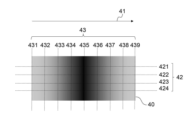
- the image recorded matter shown in FIG. 3A is an example of an image recorded matter obtained by performing image recording using the image data shown in FIG. 4A, which will be described later.
- an arrow 41 indicates the direction in which the film thickness is changing.
- the film thickness gradually increases in the direction of arrow 41 from the left side of the image recorded product, the film thickness is the thickest in the central portion of the image recorded product, and the film thickness increases in the direction of arrow 41 from the central portion. The film thickness is gradually thinned.
- a virtual parallel line 42 (421 to 424) parallel to the direction of the arrow 41 and a virtual orthogonal line 43 (431 to 424) perpendicular to the direction of the arrow 41 439) and draw. Measure the orientation angle at each intersection.
- the orientation angle shall be measured by observing the cross section from the left side of the paper surface of FIG. 3A.
- the orientation angle at each intersection is 0°.
- the orientation angle at the intersection of the virtual parallel line 421 and the virtual orthogonal line 431 is -15°
- the orientation angle at the intersection of the virtual parallel line 421 and the virtual orthogonal line 432 is -8°
- the orientation angle at the intersection of the virtual parallel line 421 and the virtual orthogonal line 432 is -8°
- the orientation angle at the intersection of the virtual parallel line 421 and the virtual orthogonal line 433 is -5°
- the orientation angle at the intersection of the virtual parallel line 421 and the virtual orthogonal line 434 is -2.5°
- the orientation angle at the intersection of the virtual parallel line 421 and the virtual orthogonal line 435 is 0°
- the orientation angle at the intersection of the virtual parallel line 436 is the orientation angle at the intersection of the virtual parallel line
- the orientation angle at the intersection of the virtual parallel line 422 and the virtual orthogonal line 431 is also ⁇ 15°.
- the orientation angle at the intersection point is also ⁇ 15°
- the orientation angle at the intersection point between the imaginary parallel line 424 and the imaginary orthogonal line 431 is also ⁇ 15°. That is, the orientation angle is substantially constant in the cross section obtained by cutting along the virtual orthogonal line 431 .
- the orientation angles are substantially constant in respective cross sections obtained by cutting along imaginary orthogonal lines 432, 433, 434, 435, 436, 437, 438, and 439.
- FIG. In the specific description of the orientation angle above, the “virtual parallel line 421” can be read as the virtual parallel line 422, the virtual parallel line 423, or the virtual parallel line 424.
- the orientation angle in the section obtained by cutting along the imaginary orthogonal line, which is the section having the largest absolute value of the orientation angle is adopted. Also, in this case, it can be seen that the orientation angle changes in the direction of arrow 41 .
- the length in the direction in which the orientation angle is changing is defined as the width length of two regions whose absolute value of the orientation angle difference is 5° or more.
- the orientation angle in the region from the virtual orthogonal line 431 to the virtual orthogonal line 434 is -15° to -2.5°
- the orientation angle in the region from the virtual orthogonal line 436 to the virtual orthogonal line 439 is 2.5°. 5° to 15°.
- both of the above distances are 1 mm or more, at least two regions in which the absolute value of the orientation angle difference is 5° or more are included, and both of the two regions are the width in the in-plane direction of the base material.
- the length is 1 mm or more. If the distance from the virtual orthogonal line 431 to the virtual orthogonal line 434 and the distance from the virtual orthogonal line 436 to the virtual orthogonal line 439 are 1 mm or more, the area from the virtual orthogonal line 431 to the virtual orthogonal line 434 and the virtual orthogonal line The area from line 436 to imaginary orthogonal line 439 corresponds to the above two areas.
- the upper limit of the absolute value of the orientation angle difference is not particularly limited, it is, for example, 25°. Also, the upper limit of the width of the two regions whose absolute value of the orientation angle difference is 5° or more is not particularly limited, but is, for example, 40 mm.
- the image recorded matter shown in FIG. 3B is an example of an image recorded matter obtained by performing image recording using the image data shown in FIG. 4B, which will be described later.
- the image data shown in FIG. 4B When the image data shown in FIG. 4B is used, there is a tendency that the ink film is smoothly formed at the boundary portions where the coverage ratios are different. Therefore, the image has a portion where the film thickness changes continuously.
- an arrow 51 indicates the direction in which the film thickness is changing.
- the film thickness is almost The film thickness is constant, and the film thickness gradually decreases in the direction of the arrow 51 in the region sandwiched between virtual orthogonal lines 533 and 537 which will be described later.
- a virtual parallel line 52 (521 to 524) and a virtual orthogonal line 53 (531 to 539) are drawn. Measure the orientation angle at each intersection.
- the orientation angle shall be measured by observing the cross section from the lower side of the paper surface of FIG. 3B.
- the orientation angle at each intersection is 0°.
- the orientation angle at the intersection of the virtual parallel line 521 and the virtual orthogonal line 531 is 0°
- the orientation angle at the intersection of the virtual parallel line 521 and the virtual orthogonal line 532 is 0°
- the orientation angle at the intersection of the virtual parallel line 521 and the virtual orthogonal line 533 is 0°
- the orientation angle at the intersection of the virtual parallel line 521 and the virtual orthogonal line 534 is -7°
- the orientation angle at the intersection of the imaginary parallel line 521 and the imaginary orthogonal line 535 is -10°
- the orientation angle at the intersection of the imaginary parallel line 521 and the imaginary orthogonal line 536 is -7°
- the orientation angle at the intersection of the virtual parallel line 521 and the virtual orthogonal line 537 is 0°
- the orientation angle at the intersection of the virtual parallel line 521 and the virtual orthogonal line 538 is 0°
- the orientation angle at each intersection of the virtual parallel line 522 and the virtual orthogonal lines 531, 532, 533, 534, 535, 536, 537, 538, 539 are respectively 0°, 0°, 0°, ⁇ 7°, ⁇ 10°, ⁇ 7°, 0°, 0°, 0°.
- the orientation angle in the cross section obtained by cutting along the virtual parallel line 521 and the orientation angle in the cross section obtained by cutting along the virtual parallel lines 522, 523, and 534 are substantially constant on the same virtual orthogonal line. be.
- the “virtual parallel line 521” can be read as the virtual parallel line 522, the virtual parallel line 523, or the virtual parallel line 524.
- the orientation angle in the section obtained by cutting along the imaginary parallel line which is the section having the largest absolute value of the orientation angle
- the orientation angle changes in the direction of arrow 51 .
- the length in the direction in which the orientation angle is changing is defined as the width length of two regions whose absolute value of the orientation angle difference is 5° or more.
- the orientation angle in the region from the virtual orthogonal line 531 to the virtual orthogonal line 533 is 0°
- the orientation in the region from the virtual orthogonal line 534 to the virtual orthogonal line 536 is 0°.
- the angle is -10° to -7°.
- both of the above distances are 1 mm or more, at least two regions in which the absolute value of the orientation angle difference is 5° or more are included, and both of the two regions are the width in the in-plane direction of the base material. It is an image record that satisfies that the length is 1 mm or more. If the distance from the virtual orthogonal line 531 to the virtual orthogonal line 533 and the distance from the virtual orthogonal line 534 to the virtual orthogonal line 536 are 1 mm or more, the area from the virtual orthogonal line 531 to the virtual orthogonal line 533 and the virtual orthogonal line The area from line 534 to imaginary orthogonal line 536 corresponds to the above two areas.
- the orientation angle in the region from the virtual orthogonal line 537 to the virtual orthogonal line 539 is 0°. to an imaginary orthogonal line 539 and an area from an imaginary orthogonal line 534 to an imaginary orthogonal line 536 may be regarded as the above two areas.
- the image recorded matter of the present disclosure includes at least two regions in which the absolute value of the orientation angle difference is 5° or more, and the width length of the two regions is 1 mm or more. , the above two regions need only exist. That is, it may be determined whether or not the above two areas exist in a part of the image recorded matter. In the case of the image recorded matter 50 shown in FIG. 3B, focusing on the change in the orientation angle, it is confirmed whether or not the above two areas exist only in the area from the virtual orthogonal line 531 to the virtual orthogonal line 536. can be done.
- the cholesteric liquid crystal layer includes at least two regions in which the absolute value of the orientation angle difference is 5° or more, and both of the two regions have a width in the in-plane direction of the substrate.
- the length is 1 mm or more.
- the image record of the present disclosure may include other areas than the at least two areas.
- the distance between the two regions where the absolute value of the orientation angle difference is 5° or more is small, from the viewpoint of enhancing the stereoscopic effect.
- regions with the shortest distance between the two regions are also referred to as region 1 and region 2, respectively.
- the distance between the regions 1 and 2 is preferably 5 mm or less, more preferably 1 mm or less, and even more preferably 0.5 mm or less.
- the absolute value of the orientation angles of the regions 1 and 2 is preferably 0° to 25°, more preferably 0° to 15°. Further, an embodiment in which the orientation angle of one of the regions 1 and 2 is ⁇ 25° to ⁇ 2.5° and the orientation angle of the other of the regions 1 and 2 is 2.5° to 25°; More preferably, the absolute value of the orientation angle of one of the regions 1 and 2 is 3° or less, and the absolute value of the orientation angle of the other is 8° or more.
- the orientation angle is preferably -5° to 5°, more preferably -1° to 1°, in at least part of the cholesteric liquid crystal layer. That is, the cholesteric liquid crystal layer preferably includes a region with an orientation angle of -5° to 5°. If the cholesteric liquid crystal layer contains a region of horizontal alignment (that is, the alignment angle is 0°) or a region close to horizontal alignment, and there is a region of high alignment angle in the adjacent region, the stereoscopic effect is obtained. is more pronounced.
- both of the two regions where the absolute value of the orientation angle difference is 5° or more have a width length of 1 mm or more in the in-plane direction of the base material, and from the viewpoint of further exhibiting the stereoscopic effect, the two regions are At least one of the regions preferably has a width of 1 mm to 40 mm in the in-plane direction of the substrate. Further, from the viewpoint of further exerting the stereoscopic effect, it is more preferable that at least one of the two regions has a width of 1 mm to 5 mm in the in-plane direction of the substrate. In particular, in at least one of the regions 1 and 2, the width in the in-plane direction of the substrate is preferably 1 mm to 40 mm, more preferably 1 mm to 5 mm.
- the image preferably includes an area having a film thickness difference of 0.5 ⁇ m or more within a width of 40 mm in the in-plane direction of the substrate. More preferably, the film thickness difference is 1 ⁇ m or more.
- the upper limit of the film thickness difference is not particularly limited, and is, for example, 30 ⁇ m. More preferably, the image includes a region having a film thickness difference of 1 ⁇ m to 30 ⁇ m within a width of 10 mm in the in-plane direction of the substrate. More preferably, the film thickness difference is 1 ⁇ m to 10 ⁇ m.
- the film thickness difference is the value obtained by subtracting the thickness of the thinnest portion of the image (i.e., minimum thickness) from the thickness of the thickest portion of the image (i.e., maximum thickness).
- the film thickness of the image is measured by the following method.
- the image record is cut along the thickness direction of the image to obtain a cross section of the image.
- a section of the image is observed using a scanning electron microscope (accelerating voltage: 2 kV, observation magnification: 5000 times and 10000 times) to measure the film thickness of the image.
- the image has a selective reflection wavelength of 460 nm or more from the viewpoint of exhibiting a stereoscopic effect.
- the selective reflection wavelength is calculated by measuring spectral reflectance with a fluorescence spectrodensitometer.
- the selective reflection wavelength is calculated using a fluorescence spectrodensitometer (product name “FD-7”, manufactured by Konica Minolta).
- FD-7 fluorescence spectrodensitometer
- a black sheet of opacity measurement paper standard: JIS K 5600, manufactured by TP Giken
- the color is measured by setting the image so that it is the outermost layer.
- another image not including a cholesteric liquid crystal layer is arranged between the substrate and the image or on the image on the substrate.
- the other image may or may not contain colorant.
- an image containing no colorant is placed between the substrate and the image or above the image on the substrate, while retaining the stereoscopic effect obtained with the present disclosure including the cholesteric liquid crystal layer, A special design property can be imparted by the difference in texture such as glossiness and the combination with the background color.
- the substrate preferably has a light transmittance of 30% or more at a wavelength of 600 nm. The image can also be visually recognized from the substrate side.
- the image recording method of the present disclosure includes a step of applying an ink containing a polymerizable liquid crystal compound, a chiral compound, and a solvent onto a substrate by an inkjet recording method (hereinafter also referred to as an “ink applying step”); A step of irradiating the ink applied on the material with an active energy ray to record an image as a cured film of the ink (hereinafter also referred to as an “active energy ray irradiation step”) is included. Then, in the ink applying step, the ink is applied under the condition that the film thickness difference within the width of 40 mm in the in-plane direction of the base material is 0.5 ⁇ m or more in the image to be recorded.
- an ink containing a polymerizable liquid crystal compound, a chiral compound, and a solvent is applied onto the substrate by an inkjet recording method.
- Only one type of ink may be applied in the ink applying step, or two or more types may be applied.
- the types and contents of the polymerizable liquid crystal compound, chiral compound, and solvent contained in each ink may be the same or different.
- a polymerizable liquid crystal compound is a liquid crystal compound having a polymerizable group.
- the liquid crystal compound may be a rod-like liquid crystal compound or a discotic liquid crystal compound, but is preferably a rod-like liquid crystal compound.
- rod-shaped liquid crystal compounds examples include rod-shaped nematic liquid crystal compounds.
- Rod-like nematic liquid crystal compounds include azomethine compounds, azoxy compounds, cyanobiphenyl compounds, cyanophenyl ester compounds, benzoic acid esters, cyclohexanecarboxylic acid phenyl esters, cyanophenylcyclohexane compounds, cyano-substituted phenylpyrimidine compounds, alkoxy-substituted phenylpyrimidine compounds, phenyl Dioxane compounds, tolan compounds or alkenylcyclohexylbenzonitrile compounds are preferably used.
- the rod-shaped liquid crystal compound not only a low-molecular-weight liquid crystal compound but also a high-molecular-weight liquid crystal compound can be used.
- a polymerizable liquid crystal compound is obtained by introducing a polymerizable group into a liquid crystal compound.
- Polymerizable groups include, for example, polymerizable unsaturated groups, epoxy groups and aziridinyl groups. Among them, the polymerizable group is preferably a polymerizable unsaturated group, and particularly preferably an ethylenically unsaturated group.
- the number of polymerizable groups possessed by the polymerizable liquid crystal compound is preferably 1 to 6, more preferably 1 to 3. From the viewpoint of the durability of the obtained image, it is more preferable that the polymerizable liquid crystal compound has two polymerizable groups in the molecule.
- polymerizable liquid crystal compound examples include the following compounds (1) to (17).
- the polymerizable liquid crystal compound is not limited to the following examples.
- each X 1 independently represents an integer of 2 to 5.
- examples of polymerizable liquid crystal compounds other than those exemplified above include cyclic organopolysiloxane compounds as disclosed in JP-A-57-165480.
- the ink may contain only one type of polymerizable liquid crystal compound, or may contain two or more types.
- the ink preferably contains two or more different polymerizable liquid crystal compounds. Color reproducibility can be further improved by using two or more kinds of polymerizable liquid crystal compounds.
- the content of the polymerizable liquid crystal compound is preferably 1% by mass to 70% by mass, more preferably 5% by mass to 60% by mass, and more preferably 15% by mass to 45% by mass with respect to the total amount of the ink. It is particularly preferred to have
- a chiral compound is also called an optically active compound.
- a chiral compound has a function of inducing a helical structure of a polymerizable liquid crystal compound. The twist direction or pitch of the induced helical structure differs depending on the type and content of the chiral compound.
- the chiral compound is not particularly limited. described) can be used, and include, for example, isosorbide derivatives and isomannide derivatives.
- a chiral compound generally contains an asymmetric carbon atom, but it may be a compound that does not contain an asymmetric carbon atom as long as it has chirality.
- Examples of chiral compounds include axially chiral compounds having a binaphthyl structure, helical chiral compounds having a helicene structure, and planar chiral compounds having a cyclophane structure.
- the chiral compound may have a polymerizable group.
- a polymer having a structural unit derived from the polymerizable liquid crystal compound and a structural unit derived from the chiral compound is produced by the polymerization reaction of the chiral compound and the polymerizable liquid crystal compound. It is formed.
- the polymerizable group is preferably the same kind of group as the polymerizable group possessed by the polymerizable liquid crystal compound.
- the polymerizable group of the chiral compound is preferably a polymerizable unsaturated group, an epoxy group or an aziridinyl group, more preferably a polymerizable unsaturated group, and particularly preferably an ethylenically unsaturated group.
- the chiral compound itself may be a liquid crystal compound.
- chiral compounds include the following compounds.
- the chiral compound that can be used in the ink composition is not limited to the following examples.
- "Me" in a compound means a methyl group.
- each X independently represents an integer of 2 to 5.
- the content of the chiral compound is preferably 1 part by mass to 15 parts by mass, more preferably 1.5 parts by mass to 5 parts by mass, with respect to 100 parts by mass of the polymerizable liquid crystalline compound in the ink composition. is more preferable.
- solvent The type of solvent is not particularly limited and can be appropriately selected depending on the purpose.
- solvents examples include ketone solvents, alkyl halide solvents, amide solvents, sulfoxide solvents, heterocyclic compounds, hydrocarbon solvents, ester solvents, and ether solvents.
- the solvent preferably contains a solvent with a boiling point of 100°C or more and less than 300°C.
- a solvent having a boiling point of 100° C. or more and less than 300° C. is contained, the ink jettability is improved.
- a boiling point means a boiling point under 1 atmosphere (101325 Pa).
- the boiling point is measured with a boiling point meter, for example, using a boiling point measuring instrument manufactured by Titan Technologies (product name "DosaTherm 300").
- ethylene glycol (boiling point: 198°C), propylene glycol (boiling point: 188°C), 1,2-butanediol (boiling point: 194°C), 2,3-butanediol (boiling point: 183°C), 2-methyl-1, 3-propanediol (boiling point: 124°C), 2-methyl-2,4-pentanediol (boiling point: 198°C), 1,2,6-hexanetriol (boiling point: 178°C), 1,2,3-butane triol (boiling point: 175°C), 1,2,4-butanetriol (boiling point: 170°C), diethylene glycol (boiling point: 244°C), dipropylene glycol (boiling point: 231°C), 1,3-propanediol (boiling point: 214°C), 1,3-butanediol
- the content of the solvent is preferably 20% by mass to 90% by mass, preferably 40% by mass to 80% by mass, and more preferably 50% by mass to 80% by mass with respect to the total amount of the ink. preferable.
- the ink preferably further contains a polymerization initiator.
- the polymerization initiator is preferably a photopolymerization initiator, and more preferably a radical polymerization initiator having a function of generating radicals upon irradiation with ultraviolet rays.
- polymerization initiators examples include alkylphenone-based photopolymerization initiators, acylphosphine oxide-based photopolymerization initiators, intramolecular hydrogen abstraction-type photopolymerization initiators, oxime ester-based photopolymerization initiators, and cationic photopolymerization initiators. agents.
- the polymerization initiator is preferably an acylphosphine oxide photopolymerization initiator, specifically, (2,4,6-trimethylbenzoyl)diphenylphosphine oxide or bis(2,4,6-trimethylbenzoyl)phenyl Phosphine oxides are preferred.
- the content of the polymerization initiator is preferably 0.1 to 20 parts by mass, more preferably 0.5 to 12 parts by mass, with respect to 100 parts by mass of the polymerizable liquid crystal compound. preferable.
- the ink may contain additives as necessary within a range that does not impair the effects of the present disclosure.
- Additives include, for example, surfactants, cross-linking agents, and non-polymerizable polymers for improving ink ejection properties.
- the polymerizable liquid crystal compound is horizontally aligned on the air interface side when the ink is cured, and the helical axis direction is controlled to be more uniform.
- the surfactant is preferably a compound capable of functioning as an alignment control agent for stably or rapidly forming a cholesteric structure of planar alignment.
- Examples of surfactants include silicone-based surfactants and fluorine-based surfactants, with fluorine-based surfactants being preferred.
- the content of the surfactant is preferably 0.01 parts by mass to 10 parts by mass, more preferably 0.01 parts by mass to 5 parts by mass, and 0.01 parts by mass with respect to 100 parts by mass of the content of the polymerizable liquid crystal compound. parts to 1 part by mass is more preferable.
- the viscosity of the ink is preferably 7 mPa ⁇ s or more, more preferably 8 mPa ⁇ s or more, and even more preferably 10 mPa ⁇ s or more.
- the upper limit of the viscosity of the ink is, for example, 30 mPa ⁇ s from the viewpoint of the ejection property of the ink.
- the viscosity of the ink is measured at 25°C using a viscometer, for example, using a viscometer (product name "RE-85L", manufactured by Toki Sangyo Co., Ltd.).
- the surface tension of the ink is preferably 20 mN/m to 40 mN/m, more preferably 23 mN/m to 35 mN/m.
- the surface tension of the ink is measured at 25°C using a surface tension meter, for example, using a surface tension meter (product name "DY-700", manufactured by Kyowa Interface Science Co., Ltd.).
- Inkjet recording method As the inkjet recording method, a generally known method can be used. method), an acoustic ink jet method in which an electric signal is converted into an acoustic beam to irradiate the ink composition and eject the ink composition using radiation pressure, and an acoustic ink jet method in which the ink composition is heated to form bubbles and the pressure generated is A thermal ink jet method to be used can be mentioned.
- image recording methods by an inkjet recording apparatus include a shuttle scan method (also referred to as a "serial head method”) in which an image is recorded using a short serial head, and a recording element corresponding to the entire width of the recording medium.
- a single-pass method also referred to as a "line head method” in which image recording is performed using a line head in which are arranged.
- the shuttle scan method image recording is performed while scanning the serial head in the width direction of the recording medium.
- the single-pass method an image can be printed on the entire surface of the printing medium by scanning the printing medium in a direction perpendicular to the array direction of the printing elements.
- the single pass method does not require a transport system such as a carriage for scanning the serial head. Further, in the single-pass method, complicated scanning control of the movement of the carriage and the print medium is not required, and only the print medium is moved, so that the printing speed can be increased compared to the shuttle scan method.
- the shuttle scan method By applying ink to the same position multiple times, the film thickness of the image can be increased. Further, when the shuttle scan method is used, coalescence of the ink droplets is suppressed, so the stereoscopic effect is enhanced.
- the ink is applied under the condition that the film thickness difference within the width of 40 mm in the in-plane direction of the substrate is 0.5 ⁇ m or more in the image to be recorded.
- the film thickness of the image to be recorded can be controlled by, for example, the amount of ejected liquid droplets, the printing rate, and the like. Therefore, as a method of making the film thickness difference of a recorded image 0.5 ⁇ m or more, there is a method of changing the amount of ejected droplets, the printing ratio, etc., depending on the position of the ink applied on the base material.
- a) A method in which the amount of liquid droplets ejected is reduced in portions where the film thickness is to be thinned, and the amount of ejected liquid droplets is increased in portions where the film thickness is to be thickened.
- b) A method in which the print rate is lowered in the portion where the film thickness is to be thinned and the print rate is increased in the portion where the film thickness is to be thickened.
- c) Any combination of a) and b).
- FIG. 4A to 4C show specific examples of image data with varying printing ratios.
- FIG. 4A is an example of image data in which the print rate is continuously changed, centering on a portion with a high print rate.
- FIG. 4B is an example of image data in which solid images with different print rates are arranged adjacently.
- FIG. 4C is an example of image data in which the print rate is continuously changed, centering on a portion with a low print rate.
- An image recorded matter 40 shown in FIG. 3A is an example of an image recorded material obtained when the image data shown in FIG. 4A is used.
- An image recorded matter 50 shown in FIG. 3B is an example of an image recorded matter obtained when the image data shown in FIG. 4B is used.
- an image recorded matter 50 shown in FIG. 3B is an example of an image recorded matter obtained when the image data shown in FIG. 4B is used.
- an image recorded matter is obtained in which the film thickness is the thinnest at the central portion and the film thickness gradually increases from the central portion toward the two opposite sides.
- the ink under the condition that the film thickness difference within the width of 40 mm in the in-plane direction of the base material is 0.5 ⁇ m or more. .
- the film thickness difference of an image to be recorded there is no particular upper limit for the film thickness difference of an image to be recorded, and it is, for example, 30 ⁇ m.
- ⁇ Active energy ray irradiation step the ink applied on the substrate is irradiated with an active energy ray to record an image, which is a cured film of the ink.
- examples of active energy rays include ultraviolet rays, visible rays, and electron beams.
- the active energy rays are preferably ultraviolet rays (hereinafter also referred to as “UV”).
- the peak wavelength of ultraviolet rays is preferably 100 nm to 405 nm, more preferably 200 nm to 395 nm.
- the amount of ultraviolet light exposure is preferably 20 mJ/cm 2 to 5 J/cm 2 , more preferably 100 mJ/cm 2 to 1,500 mJ/cm 2 .
- the irradiation conditions and basic irradiation method the irradiation conditions and irradiation method disclosed in JP-A-60-132767 can be applied.
- the irradiation method includes a method in which light sources are provided on both sides of the head unit including the ink ejection device, and the head unit and the light source are scanned by a so-called shuttle method, or a method in which a separate light source is used without driving. preferable. Among them, it is preferable to uniformly irradiate the entire image recording surface with ultraviolet rays.
- Mercury lamps, gas lasers, and solid-state lasers are mainly used as light sources for ultraviolet irradiation, and mercury lamps, metal halide lamps, and ultraviolet fluorescent lamps are widely known.
- UV-LEDs light-emitting diodes
- UV-LDs laser diodes
- the light source for ultraviolet irradiation is preferably a metal halide lamp, a high-pressure mercury lamp, a medium-pressure mercury lamp, a low-pressure mercury lamp, or a UV-LED.
- the image recording method of the present disclosure preferably further includes a step of heating the substrate (hereinafter referred to as "substrate heating step”). After the substrate heating step, the ink is preferably applied onto the heated substrate in the ink application step.
- the means for heating the substrate is not particularly limited, and examples thereof include heat drums, hot air, infrared lamps, ovens, heat plates, and hot plates.
- the heating temperature of the substrate is preferably 40°C or higher, more preferably 40°C to 100°C, even more preferably 45°C to 80°C.
- the image recording method of the present disclosure further includes a step of heating the ink applied onto the substrate after the ink application step and before the active energy ray irradiation step (hereinafter referred to as "ink heating step”). is preferably included.
- the content of the solvent in the ink after heating is preferably 50% by mass or less, more preferably 10% by mass or less, relative to the solvent content at the time the ink is applied. .
- the solvent content in the ink is preferably 50% by mass or less before the active energy ray irradiation step.
- the liquid crystal compound contained in the ink is rapidly oriented. A region having a larger absolute value of the orientation angle can be formed in the cross section along the thickness direction of the image, and the stereoscopic effect of the image recorded matter can be further exhibited.
- the lower limit of the solvent content in the ink after heating relative to the solvent content at the time the ink is applied is not particularly limited, and is, for example, 0% by mass.
- the image recording method of the present disclosure after recording an image containing the cholesteric liquid crystal layer by applying the ink onto the substrate, another image not containing the cholesteric liquid crystal layer may be recorded.
- the other image may be a specific pattern, characters, or the like, or may be a solid image.
- the substrate is a transparent substrate and the image recorded matter is observed from the side opposite to the image recording surface of the substrate, the stereoscopic effect is remarkable.
- the ink may be applied to record the image containing the cholesteric liquid crystal layer.
- the ink may be applied to record the image containing the cholesteric liquid crystal layer.
- Other images that do not include a cholesteric liquid crystal layer include, for example, color images and clear images.
- a color image is recorded by applying ink containing a coloring material, for example.
- a clear image is recorded, for example, by applying ink that does not contain a coloring material.
- the ink for recording other images is preferably an active energy ray-curable ink, and it is preferable to irradiate the active energy ray after applying the ink.
- the method of applying the ink is not particularly limited, it is preferable to apply the ink using an inkjet recording method.
- Image recordings can also be used by attaching them to walls, glass, plastic panels, building materials, displays, car decorations, lights, molded products, etc.
- Ink preparation (Ink Rm1) Ink Rm1 was prepared by mixing the components shown below.
- the viscosity (25° C.) of ink Rm1 was 11 mPa ⁇ s.
- ⁇ Diethylene glycol diethyl ether ... 62.38 parts by mass
- ⁇ Mixture A1 of polymerizable liquid crystal compound ... 34 parts by mass
- Polymerization initiator bis (2,4,6-trimethylbenzoyl) phenylphosphine oxide (product name "Omnirad 819”) ...
- the ink Rm1 forms an ink film with a selective reflection wavelength of 640 nm.
- the selective reflection wavelength of the ink film was calculated by the following method. On a PET substrate heated to 50° C., the ink was applied under the conditions of a halftone dot rate of 100% and dried at 80° C. for 5 minutes. Next, an ink film was obtained by curing with a metal halide lamp (product name: "CSOT-40, manufactured by GS Yuasa). The selective reflection wavelength was measured by using a fluorescence spectrodensitometer (product name: "FD-7", Konica (manufactured by Minolta Co., Ltd.) to measure the spectral reflectance. At the time of measurement, black paper for measuring the opacity rate (standard: JIS K 5600, manufactured by TP Giken) was placed under the substrate, and the color was measured by setting the ink film to be the outermost layer.
- a fluorescence spectrodensitometer product name: "FD-7"
- Konica manufactured by Minolta Co., Ltd.
- FIG. 4A is a schematic diagram, and in Example 1, the scale was changed as appropriate.
- a PET sheet product name “Viewful UV TP-188”, manufactured by Kimoto Co., Ltd.
- the substrate was placed on a hot plate prepared by bonding a rubber heater to a metal plate, and heated to a temperature of 70°C.
- Ink Rm1 was ejected onto the substrate heated to 70° C. using an inkjet printer (product name “UJF3042HG”, manufactured by Mimaki Engineering Co., Ltd.).
- the image resolution was set to 600 dpi ⁇ 720 dpi, the number of passes was set to 32, and the image was recorded according to the created image data.
- the substrate was further heated at 80° C. for 5 minutes, and UVA (ultraviolet A (wave) was exposed so that the cumulative exposure amount was 500 mJ/cm 2 , and an image recorded matter was obtained.
- the maximum film thickness was 2.5 ⁇ m and the minimum film thickness was 1.7 ⁇ m, and the film thickness varied continuously from the high-density portion to the low-density portion of the image data. rice field.
- Example 2 An image record was obtained in the same manner as in Example 1, except that the amount of change in printing rate in the image data was changed.
- the maximum film thickness was 2.5 ⁇ m and the minimum film thickness was 1.4 ⁇ m, and the film thickness varied continuously from the high-density portion to the low-density portion of the image data. rice field.
- Example 3 An image record was obtained in the same manner as in Example 1, except that the amount of change in printing rate in the image data was changed.
- the maximum film thickness was 2.5 ⁇ m and the minimum film thickness was 1.1 ⁇ m, and the film thickness varied continuously from the high-density portion to the low-density portion of the image data. rice field.
- Example 4 An image recorded matter was obtained in the same manner as in Example 3, except that the width of the image in the image data was changed to 20 mm.
- Example 5 An image record was obtained in the same manner as in Example 3, except that the width of the image in the image data was changed to 40 mm.
- Example 8> A solid image B with a width and length of 10 mm and a solid image C with a width and length of 10 mm, which has a printing rate lower than that of the solid image B, are arranged adjacent to each other to prepare image data shown in FIG. 4B.
- An image record was obtained in the same manner as in Example 1, except that the image data was changed.
- the maximum film thickness was 2.5 ⁇ m
- the minimum film thickness was 2.0 ⁇ m.
- Example 9 An image record was obtained in the same manner as in Example 8, except that the printing rate of image C in the image data was changed.
- the maximum film thickness was 2.5 ⁇ m
- the minimum film thickness was 1.75 ⁇ m.
- Example 10 An image record was obtained in the same manner as in Example 8, except that the printing rate of image C in the image data was changed.
- the maximum film thickness was 2.5 ⁇ m
- the minimum film thickness was 1.1 ⁇ m.
- Ink preparation (Ink Gm1) Ink Gm1 was prepared by thoroughly mixing the components shown below.
- the viscosity (25° C.) of ink Gm1 was 11 mPa ⁇ s.
- ⁇ Diethylene glycol diethyl ether ... 62.28 parts by mass
- ⁇ Mixture A1 of polymerizable liquid crystal compound ... 34 parts by mass
- Polymerization initiator bis (2,4,6-trimethylbenzoyl) phenylphosphine oxide (product name "Omnirad 819”) ... 1.8 parts by mass Chiral compound A: 1.9 parts by mass Fluorosurfactant (product name “Ftergent 208G”, manufactured by Neos): 0.02 parts by mass
- the ink Gm1 forms an ink film with a selective reflection wavelength of 550 nm.
- Ink preparation (Ink Bm1) Ink Bm1 was prepared by thoroughly mixing the components shown below.
- the viscosity (25° C.) of the ink Bm1 was 11 mPa ⁇ s.
- ⁇ Diethylene glycol diethyl ether ... 62.08 parts by mass
- ⁇ Mixture A1 of polymerizable liquid crystal compound ... 34 parts by mass
- Polymerization initiator bis (2,4,6-trimethylbenzoyl) phenylphosphine oxide (product name "Omnirad 819”) ... 1.7 parts by mass
- Chiral compound A 2.2 parts by mass Fluorosurfactant (product name “Ftergent 208G”, manufactured by Neos): 0.02 parts by mass
- the ink Bm1 was an ink forming an ink film with a selective reflection wavelength of 440 nm.
- Example 13> The print settings were changed so that the amount of ink applied was doubled, and the image data of the solid image C was used to print once. After that, the image recording surface was subjected to hydrophilic treatment using a corona surface modification evaluation device (product name "TEC-4AX", manufactured by Kasuga Denki Co., Ltd.), and the image data of image C was used again to print again.
- An image recorded matter was obtained in the same manner as in Example 8, except for the above. In the obtained image recorded matter, the maximum film thickness was 10.0 ⁇ m and the minimum film thickness was 2.0 ⁇ m.
- Example 14> The print settings were changed so that the amount of ink applied was doubled, and the image data of the solid image C was used to print once. After that, the image recording surface is subjected to hydrophilic treatment using a corona surface modification evaluation device (product name “TEC-4AX”, manufactured by Kasuga Denki Co., Ltd.), and the image data of image C is superimposed and printed. bottom. Further, an image recorded matter was obtained in the same manner as in Example 8, except that the image recording surface was subjected to the same hydrophilization treatment as described above, and the image data of image C was used for printing. . The obtained image recorded matter had a maximum film thickness of 18.0 ⁇ m and a minimum film thickness of 8.0 ⁇ m.
- Image data was prepared by arranging a solid image B with a width and length of 10 mm and a solid image D with a width and length of 10 mm adjacent to each other.
- Solid image B has a printing rate of ink Rm1 of 100%
- solid image C has a printing rate of ink Rm1 of 40% and a printing rate of ink Bm1 of 60%.
- the substrate temperature was set to 70° C.
- ink Rm1 and ink Bm1 were ejected from each head, and image recording was performed according to the prepared image data.
- the film thickness of the resulting image record was 3.0 ⁇ m.
- Image data shown in FIG. 4B was prepared by arranging a solid image E with a width and length of 10 mm and a solid image F with a width and length of 10 mm adjacent to each other.
- Solid image E has a printing rate of ink Rm1 of 100% and ink Bm1 of 50%.
- Solid image F has a printing rate of ink Rm1 of 50% and ink Bm1 of 50%.
- the substrate temperature was set to 70° C., ink Rm1 and ink Bm1 were ejected from each head, and image recording was performed according to the prepared image data.
- the film thickness of the solid image E was 4.5 ⁇ m
- the film thickness of the solid image F was 3.0 ⁇ m.
- Image data shown in FIG. 4B was prepared by arranging a solid image G with a width and length of 10 mm and a solid image H with a width and length of 10 mm adjacent to each other.
- Solid image G has a printing rate of ink Rm1 of 100%, ink Bm1 of 25%, and ink Gm1 of 25%.
- Solid image H has a printing rate of ink Rm1 of 50%, ink Bm1 of The print rate was set to 25%, and the print rate of ink Gm1 was set to 25%.
- the temperature of the base material was set to 70° C., ink Rm1, ink Bm1, and ink Gm1 were ejected from each head, and image recording was performed according to the created image data.
- the film thickness of the solid image G was 4.5 ⁇ m
- the film thickness of the solid image H was 3.0 ⁇ m.
- Image data shown in FIG. 4B was prepared by arranging a solid image I with a width and length of 10 mm and a solid image J with a width and length of 10 mm adjacent to each other.
- Solid image I has a printing rate of 100% for ink Rm1 and 100% for ink Gm1
- solid image J has a printing rate of 50% for ink Rm1 and 50% for ink Gm1.
- the temperature of the base material was set to 70° C.
- the ink Rm1 and the ink Gm1 were ejected from each head, and image recording was performed according to the prepared image data.
- the film thickness of the solid image I was 6.0 ⁇ m
- the film thickness of the solid image J was 3.0 ⁇ m.
- Ink preparation (Ink Rm2) Ink Rm2 was prepared by mixing 1 part by mass of FLORSTAB UV12 (manufactured by Kromachem) instead of 1 part by mass of diethylene glycol diethyl ether in ink Rm1.
- the viscosity (25° C.) of ink Rm2 was 11 mPa ⁇ s.
- the maximum film thickness was 3.0 ⁇ m and the minimum film thickness was 1.3 ⁇ m, and the film thickness varied continuously from the high-density portion to the low-density portion of the image data. rice field.
- the ink Rm2 was an ink forming an ink film with a selective reflection wavelength of 640 nm.
- Ink preparation (Ink Rm3) Ink Rm3 was prepared in the same manner as Ink Rm1, except that chiral compound A was 1.4 parts by mass, FLORSTAB UV12 (manufactured by Kromachem) was 1 part by mass, and diethylene glycol diethyl ether was 61.58 parts by mass. prepared. The viscosity (25° C.) of ink Rm3 was 11 mPa ⁇ s. An image recorded matter was obtained in the same manner as in Example 19 using ink Rm3. When the reflectance in the visible light region of the ink film formed with the ink Rm3 was measured, the ink Rm3 was an ink forming an ink film with a selective reflection wavelength of 700 nm.
- Example 21 An image record was obtained in the same manner as in Example 1, except that the amount of change in printing rate in the image data was changed.
- the maximum film thickness was 7.0 ⁇ m and the minimum film thickness was 3.0 ⁇ m, and the film thickness varied continuously from the high-density portion to the low-density portion of the image data. rice field.
- ⁇ Comparative Example 3> An image record was obtained in the same manner as in Example 8, except that the printing rate of image C in the image data was changed.
- ⁇ Comparative Example 4> After the ink was applied to the entire surface of the substrate so that the film thickness was 2.5 ⁇ m, the substrate was dried at 95° C. for 60 seconds. After the temperature was lowered from 95°C to 25°C at a rate of -7°C/s, exposure was performed at 25°C to obtain an image record.
- regions with the shortest distance between the two regions were defined as region 1 and region 2, respectively.
- the orientation angles of the regions 1 and 2 and the width lengths of the regions 1 and 2 are shown in Tables 1 and 2.
- Tables 1 and 2 in Comparative Examples 1 to 4, the absolute value of the orientation angle difference was 5° or more and the width length was 1 mm or more. and "-" in the column related to region 2.
- the orientation angles of Area 1 and Area 2 were measured in the same manner as for the image recorded matter 40 shown in FIG. 3A.
- Example 1 to 7 and Examples 19 to 21 the orientation angle was measured by focusing on the region (full width region) corresponding to the virtual orthogonal line 431 to the virtual orthogonal line 439 shown in FIG. 3A. .
- the orientation angles of Area 1 and Area 2 were measured in the same manner as for the image recorded matter 50 shown in FIG. 3B.
- the orientation angles were measured by focusing on the region corresponding to the virtual orthogonal line 531 to the virtual orthogonal line 536 shown in FIG. 3B.
- Example 15 the direction orthogonal to the 20 mm width of the image recorded matter (the sum of the 10 mm width of the solid image B and the 10 mm width of the solid image D) is assumed to be the virtual orthogonal lines 431 to 439 shown in FIG. was measured.
- the image record was placed horizontally on the black portion of the paper for measuring the concealment rate, and the image record was observed from the normal direction and the direction at 60° from the normal direction. Specifically, by changing the observation direction, it was confirmed whether or not the color development changed and looked like a shadow, and the degree of the shadow was determined. If the coloring property changes and it looks like a shadow, it can be said that there is a stereoscopic effect.
- B A shadow can be visually recognized, and the width of the shadow is large.
- C A shadow can be visually recognized.
- D A shadow is slightly visible.
- E No stereoscopic effect.
- Examples 1-21 include a substrate and an image recorded on the substrate, the image including a cholesteric liquid crystal layer, the cholesteric liquid crystal layer comprising: In the cross section along the thickness direction of the image, it has a striped pattern of bright and dark parts observed with a scanning electron microscope, and the angle between the continuous line that is the bright or dark part and the main surface of the substrate is oriented. When expressed as an angle, it includes at least two regions in which the absolute value of the difference in orientation angle is 5° or more, and each of the two regions has a width of 1 mm or more in the in-plane direction of the base material, A stereoscopic effect was obtained for the recorded image.
- Example 101 After an image was recorded on the substrate in the same manner as in Example 10, a 100% solid black image was recorded using an inkjet printer (product name: "Acuity LED 1600II", manufactured by FUJIFILM Corporation).
- Example 102 After an image was recorded on the substrate in the same manner as in Example 10, a white 100% solid image was recorded using an inkjet printer (product name: "Acuity LED 1600II", manufactured by FUJIFILM Corporation).
- Example 103 After an image was recorded on the substrate in the same manner as in Example 10, the image was laminated to a transparent vinyl chloride sheet.
- Example 104 After an image was recorded on the substrate in the same manner as in Example 10, the image and glass were bonded together.
Landscapes
- Physics & Mathematics (AREA)
- General Physics & Mathematics (AREA)
- Chemical & Material Sciences (AREA)
- Engineering & Computer Science (AREA)
- Theoretical Computer Science (AREA)
- Marketing (AREA)
- Business, Economics & Management (AREA)
- Life Sciences & Earth Sciences (AREA)
- Accounting & Taxation (AREA)
- Materials Engineering (AREA)
- Wood Science & Technology (AREA)
- Organic Chemistry (AREA)
- Optics & Photonics (AREA)
- Ink Jet Recording Methods And Recording Media Thereof (AREA)
Abstract
L'invention concerne un objet enregistré sur image et une application de celui-ci. L'objet enregistré sur image comprend un substrat et une image qui est enregistrée sur le substrat. L'image comprend une couche de cristaux liquides cholestériques. La couche de cristaux liquides cholestériques comporte, dans une section transversale allant dans le sens de l'épaisseur de l'image, un motif de rayures ayant des sections claires et des sections sombres tel qu'observé par un microscope électronique à balayage, et elle comprend au moins deux régions dans lesquelles la valeur absolue d'une différence d'angle d'alignement est supérieure ou égale à 5° lorsqu'un angle entre une surface principale du substrat et une ligne continue qui est la section claire ou la section sombre est défini comme un angle d'alignement. La largeur de chacune des deux régions dans le sens dans le plan du substrat est supérieure ou égale à 1 mm.
Applications Claiming Priority (4)
| Application Number | Priority Date | Filing Date | Title |
|---|---|---|---|
| JP2021185021 | 2021-11-12 | ||
| JP2021-185021 | 2021-11-12 | ||
| JP2022091690 | 2022-06-06 | ||
| JP2022-091690 | 2022-06-06 |
Publications (1)
| Publication Number | Publication Date |
|---|---|
| WO2023085370A1 true WO2023085370A1 (fr) | 2023-05-19 |
Family
ID=86335881
Family Applications (1)
| Application Number | Title | Priority Date | Filing Date |
|---|---|---|---|
| PCT/JP2022/041962 WO2023085370A1 (fr) | 2021-11-12 | 2022-11-10 | Objet enregistré sur image et procédé d'enregistrement d'image |
Country Status (1)
| Country | Link |
|---|---|
| WO (1) | WO2023085370A1 (fr) |
Citations (2)
| Publication number | Priority date | Publication date | Assignee | Title |
|---|---|---|---|---|
| WO2018043678A1 (fr) * | 2016-09-01 | 2018-03-08 | 富士フイルム株式会社 | Feuille décorative, dispositif d'affichage à cristaux liquides et intérieur pour automobile |
| WO2019035449A1 (fr) * | 2017-08-14 | 2019-02-21 | 富士フイルム株式会社 | Structure et procédé pour former une couche réfléchissante |
-
2022
- 2022-11-10 WO PCT/JP2022/041962 patent/WO2023085370A1/fr unknown
Patent Citations (2)
| Publication number | Priority date | Publication date | Assignee | Title |
|---|---|---|---|---|
| WO2018043678A1 (fr) * | 2016-09-01 | 2018-03-08 | 富士フイルム株式会社 | Feuille décorative, dispositif d'affichage à cristaux liquides et intérieur pour automobile |
| WO2019035449A1 (fr) * | 2017-08-14 | 2019-02-21 | 富士フイルム株式会社 | Structure et procédé pour former une couche réfléchissante |
Similar Documents
| Publication | Publication Date | Title |
|---|---|---|
| KR102089204B1 (ko) | 투명 필름, 투명 스크린 및 화상 표시 시스템과 투명 포스터 | |
| CN103221851B (zh) | 液晶膜 | |
| JP6453450B2 (ja) | 透明スクリーン | |
| JP3697131B2 (ja) | カラーフィルタの製造方法、製造装置、カラーフィルタを備えた表示装置の製造方法及び該表示装置を備えた装置の製造方法 | |
| KR101011357B1 (ko) | 미소 착색 패턴 결함 수정용 잉크, 컬러 필터, 착색패턴의 미소 결함을 수정하는 방법, 및 잉크의 제조 방법 | |
| CN108022994A (zh) | 具有变化的视角的光控制膜 | |
| CN1942813A (zh) | 具有垂直排列液晶膜的延迟膜及其制备方法 | |
| CN105848917A (zh) | 在基材上印刷装饰图案的方法 | |
| JPWO2018169095A1 (ja) | コレステリック液晶層を有する透明スクリーン、および透明スクリーンシステム | |
| JP6639521B2 (ja) | 光学機能性層作製用組成物、光学フィルム、および液晶表示装置 | |
| JP6833023B2 (ja) | バックライトユニットおよび液晶表示装置 | |
| US11453230B2 (en) | Image forming method | |
| EP4036131B1 (fr) | Procédé d'enregistrement d'image | |
| KR20170047304A (ko) | 하드 코트 필름, 하드 코트 필름의 제조 방법, 편광판, 및 액정 표시 장치 | |
| CN108027466A (zh) | 光学膜及其制造方法 | |
| WO2023085370A1 (fr) | Objet enregistré sur image et procédé d'enregistrement d'image | |
| EP1079262A2 (fr) | Procédé et appareil de fabrication d'un filtre coloré | |
| WO2022138142A1 (fr) | Procédé d'impression d'image et matière imprimée par jet d'encre | |
| JP2004182875A (ja) | カチオン重合性光硬化インク用洗浄液及びインクジェットプリンタのクリーニング方法 | |
| JP5055811B2 (ja) | カラーフィルタ、その製造方法、及び液晶ディスプレイ | |
| JP2001272522A (ja) | カラーフィルターの作製方法、カラーフィルター並びに画像表示装置及び画像入力装置 | |
| CN1534318A (zh) | 叠层偏光膜 | |
| US20240036389A1 (en) | Decorative sheet, display device, and automobile interior material | |
| JP2548021B2 (ja) | 像形成媒体、像形成装置、表示装置及びメモリ装置 | |
| JP2009244406A (ja) | カラーフィルタ製造方法及び製造装置、並びにカラーフィルタ及び液晶表示装置 |
Legal Events
| Date | Code | Title | Description |
|---|---|---|---|
| 121 | Ep: the epo has been informed by wipo that ep was designated in this application |
Ref document number: 22892868 Country of ref document: EP Kind code of ref document: A1 |