WO2023085370A1 - Image recorded object and image recording method - Google Patents
Image recorded object and image recording method Download PDFInfo
- Publication number
- WO2023085370A1 WO2023085370A1 PCT/JP2022/041962 JP2022041962W WO2023085370A1 WO 2023085370 A1 WO2023085370 A1 WO 2023085370A1 JP 2022041962 W JP2022041962 W JP 2022041962W WO 2023085370 A1 WO2023085370 A1 WO 2023085370A1
- Authority
- WO
- WIPO (PCT)
- Prior art keywords
- image
- ink
- substrate
- liquid crystal
- orientation angle
- Prior art date
Links
Images


Classifications
-
- B—PERFORMING OPERATIONS; TRANSPORTING
- B41—PRINTING; LINING MACHINES; TYPEWRITERS; STAMPS
- B41J—TYPEWRITERS; SELECTIVE PRINTING MECHANISMS, i.e. MECHANISMS PRINTING OTHERWISE THAN FROM A FORME; CORRECTION OF TYPOGRAPHICAL ERRORS
- B41J2/00—Typewriters or selective printing mechanisms characterised by the printing or marking process for which they are designed
- B41J2/005—Typewriters or selective printing mechanisms characterised by the printing or marking process for which they are designed characterised by bringing liquid or particles selectively into contact with a printing material
- B41J2/01—Ink jet
-
- B—PERFORMING OPERATIONS; TRANSPORTING
- B41—PRINTING; LINING MACHINES; TYPEWRITERS; STAMPS
- B41M—PRINTING, DUPLICATING, MARKING, OR COPYING PROCESSES; COLOUR PRINTING
- B41M5/00—Duplicating or marking methods; Sheet materials for use therein
-
- C—CHEMISTRY; METALLURGY
- C09—DYES; PAINTS; POLISHES; NATURAL RESINS; ADHESIVES; COMPOSITIONS NOT OTHERWISE PROVIDED FOR; APPLICATIONS OF MATERIALS NOT OTHERWISE PROVIDED FOR
- C09D—COATING COMPOSITIONS, e.g. PAINTS, VARNISHES OR LACQUERS; FILLING PASTES; CHEMICAL PAINT OR INK REMOVERS; INKS; CORRECTING FLUIDS; WOODSTAINS; PASTES OR SOLIDS FOR COLOURING OR PRINTING; USE OF MATERIALS THEREFOR
- C09D11/00—Inks
- C09D11/02—Printing inks
- C09D11/10—Printing inks based on artificial resins
- C09D11/101—Inks specially adapted for printing processes involving curing by wave energy or particle radiation, e.g. with UV-curing following the printing
-
- C—CHEMISTRY; METALLURGY
- C09—DYES; PAINTS; POLISHES; NATURAL RESINS; ADHESIVES; COMPOSITIONS NOT OTHERWISE PROVIDED FOR; APPLICATIONS OF MATERIALS NOT OTHERWISE PROVIDED FOR
- C09D—COATING COMPOSITIONS, e.g. PAINTS, VARNISHES OR LACQUERS; FILLING PASTES; CHEMICAL PAINT OR INK REMOVERS; INKS; CORRECTING FLUIDS; WOODSTAINS; PASTES OR SOLIDS FOR COLOURING OR PRINTING; USE OF MATERIALS THEREFOR
- C09D11/00—Inks
- C09D11/30—Inkjet printing inks
- C09D11/32—Inkjet printing inks characterised by colouring agents
-
- G—PHYSICS
- G02—OPTICS
- G02B—OPTICAL ELEMENTS, SYSTEMS OR APPARATUS
- G02B5/00—Optical elements other than lenses
- G02B5/20—Filters
-
- G—PHYSICS
- G02—OPTICS
- G02B—OPTICAL ELEMENTS, SYSTEMS OR APPARATUS
- G02B5/00—Optical elements other than lenses
- G02B5/30—Polarising elements
-
- G—PHYSICS
- G09—EDUCATION; CRYPTOGRAPHY; DISPLAY; ADVERTISING; SEALS
- G09F—DISPLAYING; ADVERTISING; SIGNS; LABELS OR NAME-PLATES; SEALS
- G09F19/00—Advertising or display means not otherwise provided for
- G09F19/12—Advertising or display means not otherwise provided for using special optical effects
- G09F19/14—Advertising or display means not otherwise provided for using special optical effects displaying different signs depending upon the view-point of the observer
Definitions
- the present disclosure relates to an image recorded matter and an image recording method.
- International Publication No. 2018/043678 has a cholesteric liquid crystal layer having wavelength-selective reflectivity, and the cholesteric liquid crystal layer has a striped pattern of bright and dark portions observed with a scanning electron microscope in cross section. and the striped pattern has a wavy structure, and the average value of the peak-to-peak distances of the wavy structure is 0.5 ⁇ m to 50 ⁇ m.
- the present disclosure includes the following aspects. ⁇ 1> comprising a substrate and an image recorded on the substrate;
- the image includes a cholesteric liquid crystal layer,
- the cholesteric liquid crystal layer has a striped pattern of bright and dark areas observed with a scanning electron microscope (hereinafter sometimes abbreviated as "SEM") in a cross section along the thickness direction of the image, At least two regions in which the absolute value of the difference in the orientation angle is 5° or more when the angle between the continuous line, which is the light or dark portion, and the main surface of the substrate is the orientation angle,
- SEM scanning electron microscope
- ⁇ 2> The recorded image according to ⁇ 1>, wherein the orientation angle is -5° to 5° in at least part of the cholesteric liquid crystal layer.
- ⁇ 3> The image recorded matter according to ⁇ 1> or ⁇ 2>, wherein at least one of the two regions has a width of 1 mm to 40 mm in the in-plane direction of the substrate.
- ⁇ 4> The image is The image recorded matter according to any one of ⁇ 1> to ⁇ 3>, including a region having a film thickness difference of 0.5 ⁇ m or more within a width of 40 mm in the in-plane direction of the substrate.
- the image is The image recorded matter according to any one of ⁇ 1> to ⁇ 4>, including a region having a film thickness difference of 1 ⁇ m to 30 ⁇ m within a width of 10 mm in the in-plane direction of the substrate.
- ⁇ 6> The image recorded matter according to any one of ⁇ 1> to ⁇ 6>, wherein the image has a selective reflection wavelength of 460 nm or more.
- ⁇ 7> Any one of ⁇ 1> to ⁇ 5>, wherein another image not containing a cholesteric liquid crystal layer is further arranged between the substrate and the image or on the image on the substrate.
- image recordings of ⁇ 8> A step of applying an ink containing a polymerizable liquid crystal compound, a chiral compound, and a solvent onto a substrate by an inkjet recording method; A step of irradiating the ink applied on the base material with an active energy ray to record an image, which is a cured film of the ink; including In the step of applying the ink, an image recording method in which the ink is applied under the condition that the film thickness difference within a width of 40 mm in the in-plane direction of the substrate is 0.5 ⁇ m or more in the image to be recorded.
- the solvent contains a solvent having a boiling point of 100°C or higher and lower than 300°C.
- ⁇ 10> further comprising heating the substrate to 45° C. or higher;
- ⁇ 11> After the step of applying the ink and before the step of irradiating the active energy ray, further comprising heating the ink applied on the substrate, In the step of heating the ink, any one of ⁇ 8> to ⁇ 10>, wherein the content of the solvent in the ink after heating is 50% by mass or less with respect to the content of the solvent at the time of applying the ink.
- an image recorded matter and an image recording method that provide a stereoscopic effect are provided.
- FIG. 1 is a schematic diagram showing a striped pattern of bright portions and dark portions observed by SEM of a cross section of an image recording material, and is a diagram for explaining the orientation angle.
- FIG. 2 is a diagram for explaining a method of confirming a change in orientation angle.
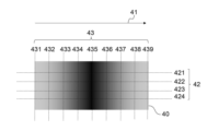
- FIG. 3A is a schematic top view of an image recorded matter with varying film thicknesses.
- FIG. 3B is a schematic top view of an image recorded matter with varying film thicknesses.
- FIG. 4A is an example of image data in which the print rate is continuously changed, centering on a portion with a high print rate.
- FIG. 4B is an example of image data in which solid images with different print rates are arranged adjacently.
- FIG. 4C is an example of image data in which the print rate is continuously changed, centering on a portion with a low print rate.
- the numerical range indicated using “to” means a range including the numerical values before and after “to” as the minimum and maximum values, respectively.
- the upper limit or lower limit described in a certain numerical range may be replaced with the upper limit or lower limit of another numerical range described stepwise.
- the upper limit or lower limit described in a certain numerical range may be replaced with the values shown in the examples.
- the amount of each component in the composition refers to the total amount of the multiple substances present in the composition when there are multiple substances corresponding to each component in the composition, unless otherwise specified.
- step is used not only for independent steps, but also for cases where the intended purpose of the step is achieved, even if it cannot be clearly distinguished from other steps. include.
- the image recorded matter of the present disclosure includes a substrate and an image recorded on the substrate, the image includes a cholesteric liquid crystal layer, and the cholesteric liquid crystal layer is scanned in a cross section along the thickness direction of the image.
- the absolute difference in the orientation angle when the orientation angle is the angle between the continuous line, which is the bright or dark area, and the main surface of the substrate, which has a striped pattern of bright and dark areas observed with a type electron microscope.
- At least two regions having a value of 5° or more are included, and each of the two regions has a width length of 1 mm or more in the in-plane direction of the substrate.
- the striped pattern observed in the SEM of the image cross section there are two regions where the absolute value of the difference in the orientation angle is 5 ° or more, and the width of each region is 1 mm or more.
- parts of the image appear to be shadowed.
- the presence of shadows makes it possible to visually recognize a macroscopically flat image as if it were three-dimensional.
- a remarkable stereoscopic effect can be obtained.
- the background color is white and observed, there is a portion where glossiness becomes noticeable depending on the angle, and a stereoscopic effect can be obtained by locally shining.
- the background color is other than white and black, the same stereoscopic effect can be obtained.
- the striped pattern observed by SEM of the image cross section has a wavy structure, and the average value of the peak-to-peak distance of the wavy structure is 0.5 ⁇ m to 50 ⁇ m. Therefore, it exhibits high brightness even when viewed from a direction away from the specular reflection of the illumination light, and does not focus on the stereoscopic effect.
- An image record of the present disclosure includes a substrate.
- the base material is not particularly limited, and any base material can be selected.
- the substrate may be an ink-absorbing substrate, a low-ink-absorbing substrate, or a non-ink-absorbing substrate.
- Substrates include, for example, paper, leather, cloth, and resin. Above all, from the viewpoint of color development, the substrate is preferably an ink-non-absorbing substrate, and more preferably a resin substrate.
- the resin constituting the resin base material examples include cellulose diacetate, cellulose triacetate, cellulose propionate, cellulose butyrate, cellulose acetate butyrate, cellulose nitrate, acrylic resin, chlorinated polyolefin resin, polyethersulfone resin, and polyethylene terephthalate. (PET), polyethylene naphthalate, nylon, polyethylene, polystyrene, polypropylene, polycycloolefin resin, polyimide resin, polycarbonate resin, and polyvinyl acetal.
- the resin base material may be a base material containing only one of these resins, or may be a base material in which two or more of these resins are mixed. Moreover, other layers such as an easy-adhesion layer, an antistatic layer, and an antifouling layer may be formed on these resins, and the surface of the base material may be subjected to hydrophilic treatment.
- the thickness of the base material is not particularly limited, and is, for example, 1 ⁇ m to 10 mm.
- An image record of the present disclosure includes an image recorded on a substrate.
- the image includes a cholesteric liquid crystal layer, and the cholesteric liquid crystal layer has a striped pattern of bright and dark portions observed by SEM in a cross section along the thickness direction of the image, and a continuous line that is a bright or dark portion.
- the main surface of the substrate is the orientation angle, the absolute value of the difference in orientation angle is 5 ° or more.
- the width length in the direction is 1 mm or more.
- a cholesteric liquid crystal layer is a layer containing at least a cholesteric liquid crystal phase.
- a cholesteric liquid crystal phase means a phase in which liquid crystal molecules are helically arranged. In the case of the cholesteric liquid crystal layer, a striped pattern of bright and dark portions is observed by SEM.
- a striped pattern of bright and dark areas observed by SEM can be confirmed by, for example, the following method.
- the image is cut through the thickness of the image to obtain cross-sectional samples.
- a cross-sectional SEM image is observed using a scanning electron microscope (accelerating voltage: 2 kV, observation magnification: 5000 and 10000 times). It can be confirmed that there is a dark and light striped pattern due to the change in the refractive index of the cholesteric liquid crystal phase.
- black portions are referred to as dark portions
- white portions are referred to as bright portions.
- one cycle of bright and dark areas corresponds to the 180-degree twist of the liquid crystal. Therefore, the two cycles of the bright portion and the dark portion correspond to 360 degrees of twist of the liquid crystal. That is, the width of two cycles of the bright portion and the dark portion corresponds to the length of the helical pitch in the cholesteric liquid crystal layer.
- the normal direction of the continuous line which is the bright portion or the dark portion, means the direction of the helical axis in the cholesteric liquid crystal layer.
- the orientation angle is the angle between the continuous line, which is the bright portion or the dark portion, and the main surface of the substrate.
- the main surface of the substrate refers to the surface with the widest area among the surfaces of the substrate.
- FIG. 1 is a schematic diagram showing a striped pattern of bright and dark portions observed by SEM of a cross section of an image recorded product in which an image 2 is recorded on a substrate 1, and is used for explaining the orientation angle. It is a diagram. For example, as shown in FIG. 1, a straight line 21 is drawn along the continuous line of the dark area. As the orientation angle, the angle ⁇ 1 between the main surface 11 of the substrate and the straight line 21 is measured.
- the orientation angle is positive when the straight line is upward-sloping (that is, has a positive slope in the XY coordinates), and is represented as a plus when the straight line is downward-sloping (that is, it has a negative slope in the XY coordinates). ), it shall be expressed as a minus. Therefore, in FIG. 1, the angle ⁇ 1 is represented by a plus.
- FIG. 2 is a diagram for explaining a method of confirming a change in orientation angle.
- first virtual line 32 (first virtual lines 321 to 324 in FIG. 2) is drawn at an arbitrary position on the image record 30 .
- second virtual line 33 (second virtual lines 331 to 339 in FIG. 2) orthogonal to the first virtual line is drawn.
- the first virtual lines 321-324 are parallel to each other and the second virtual lines 331-339 are parallel to each other.
- the number of first virtual lines and second virtual lines is not particularly limited.
- the directions of the first virtual line and the second virtual line are not particularly limited as long as they are orthogonal to each other.
- the directions of the first virtual line and the second virtual line are the direction parallel to the direction in which the film thickness changes. is preferably perpendicular to the direction in which .
- the direction in which the film thickness is changing can be confirmed by visually observing the image recorded matter having the film thickness difference.
- the film thickness is changing includes a mode in which the film thickness increases and a mode in which the film thickness decreases in an arbitrary direction. Further, the film thickness may vary over the entire image recorded matter, or may vary only in part of the image recorded matter.
- the orientation angle at the intersection of the first virtual line and the second virtual line is measured. , measured according to the method for measuring the orientation angle described above.
- the intersection points t1, t2, and t3 shown in FIG. 2 are the intersection points of the first virtual line 321 and the second virtual lines 331, 332, and 333 in the cross section obtained by cutting along the first virtual line 321. be.
- the orientation angle at the intersection of the first virtual line and the second virtual line is measured according to the orientation angle measurement method described above.
- the intersection points s1, s2, and s3 shown in FIG. 2 are the intersection points of the second virtual line 338 and the first virtual lines 321, 322, and 323 in the cross section obtained by cutting along the second virtual line 338. be.
- the change direction of the orientation angle can be determined.
- the length in the direction in which the orientation angle is changing is defined as the width length of two regions whose absolute value of the orientation angle difference is 5° or more.
- the change in the orientation angle in the cross section obtained by cutting along the first virtual line, the change in the orientation angle can be confirmed, and in the cross section obtained by cutting along the second virtual line, the orientation is confirmed. and a mode in which a change in angle can be confirmed.
- a method for identifying two regions in which the absolute value of the orientation angle difference is 5° or more in the above two modes will be described using an image recorded matter having a film thickness difference.
- the image recorded matter shown in FIG. 3A is an example of an image recorded matter obtained by performing image recording using the image data shown in FIG. 4A, which will be described later.
- an arrow 41 indicates the direction in which the film thickness is changing.
- the film thickness gradually increases in the direction of arrow 41 from the left side of the image recorded product, the film thickness is the thickest in the central portion of the image recorded product, and the film thickness increases in the direction of arrow 41 from the central portion. The film thickness is gradually thinned.
- a virtual parallel line 42 (421 to 424) parallel to the direction of the arrow 41 and a virtual orthogonal line 43 (431 to 424) perpendicular to the direction of the arrow 41 439) and draw. Measure the orientation angle at each intersection.
- the orientation angle shall be measured by observing the cross section from the left side of the paper surface of FIG. 3A.
- the orientation angle at each intersection is 0°.
- the orientation angle at the intersection of the virtual parallel line 421 and the virtual orthogonal line 431 is -15°
- the orientation angle at the intersection of the virtual parallel line 421 and the virtual orthogonal line 432 is -8°
- the orientation angle at the intersection of the virtual parallel line 421 and the virtual orthogonal line 432 is -8°
- the orientation angle at the intersection of the virtual parallel line 421 and the virtual orthogonal line 433 is -5°
- the orientation angle at the intersection of the virtual parallel line 421 and the virtual orthogonal line 434 is -2.5°
- the orientation angle at the intersection of the virtual parallel line 421 and the virtual orthogonal line 435 is 0°
- the orientation angle at the intersection of the virtual parallel line 436 is the orientation angle at the intersection of the virtual parallel line
- the orientation angle at the intersection of the virtual parallel line 422 and the virtual orthogonal line 431 is also ⁇ 15°.
- the orientation angle at the intersection point is also ⁇ 15°
- the orientation angle at the intersection point between the imaginary parallel line 424 and the imaginary orthogonal line 431 is also ⁇ 15°. That is, the orientation angle is substantially constant in the cross section obtained by cutting along the virtual orthogonal line 431 .
- the orientation angles are substantially constant in respective cross sections obtained by cutting along imaginary orthogonal lines 432, 433, 434, 435, 436, 437, 438, and 439.
- FIG. In the specific description of the orientation angle above, the “virtual parallel line 421” can be read as the virtual parallel line 422, the virtual parallel line 423, or the virtual parallel line 424.
- the orientation angle in the section obtained by cutting along the imaginary orthogonal line, which is the section having the largest absolute value of the orientation angle is adopted. Also, in this case, it can be seen that the orientation angle changes in the direction of arrow 41 .
- the length in the direction in which the orientation angle is changing is defined as the width length of two regions whose absolute value of the orientation angle difference is 5° or more.
- the orientation angle in the region from the virtual orthogonal line 431 to the virtual orthogonal line 434 is -15° to -2.5°
- the orientation angle in the region from the virtual orthogonal line 436 to the virtual orthogonal line 439 is 2.5°. 5° to 15°.
- both of the above distances are 1 mm or more, at least two regions in which the absolute value of the orientation angle difference is 5° or more are included, and both of the two regions are the width in the in-plane direction of the base material.
- the length is 1 mm or more. If the distance from the virtual orthogonal line 431 to the virtual orthogonal line 434 and the distance from the virtual orthogonal line 436 to the virtual orthogonal line 439 are 1 mm or more, the area from the virtual orthogonal line 431 to the virtual orthogonal line 434 and the virtual orthogonal line The area from line 436 to imaginary orthogonal line 439 corresponds to the above two areas.
- the upper limit of the absolute value of the orientation angle difference is not particularly limited, it is, for example, 25°. Also, the upper limit of the width of the two regions whose absolute value of the orientation angle difference is 5° or more is not particularly limited, but is, for example, 40 mm.
- the image recorded matter shown in FIG. 3B is an example of an image recorded matter obtained by performing image recording using the image data shown in FIG. 4B, which will be described later.
- the image data shown in FIG. 4B When the image data shown in FIG. 4B is used, there is a tendency that the ink film is smoothly formed at the boundary portions where the coverage ratios are different. Therefore, the image has a portion where the film thickness changes continuously.
- an arrow 51 indicates the direction in which the film thickness is changing.
- the film thickness is almost The film thickness is constant, and the film thickness gradually decreases in the direction of the arrow 51 in the region sandwiched between virtual orthogonal lines 533 and 537 which will be described later.
- a virtual parallel line 52 (521 to 524) and a virtual orthogonal line 53 (531 to 539) are drawn. Measure the orientation angle at each intersection.
- the orientation angle shall be measured by observing the cross section from the lower side of the paper surface of FIG. 3B.
- the orientation angle at each intersection is 0°.
- the orientation angle at the intersection of the virtual parallel line 521 and the virtual orthogonal line 531 is 0°
- the orientation angle at the intersection of the virtual parallel line 521 and the virtual orthogonal line 532 is 0°
- the orientation angle at the intersection of the virtual parallel line 521 and the virtual orthogonal line 533 is 0°
- the orientation angle at the intersection of the virtual parallel line 521 and the virtual orthogonal line 534 is -7°
- the orientation angle at the intersection of the imaginary parallel line 521 and the imaginary orthogonal line 535 is -10°
- the orientation angle at the intersection of the imaginary parallel line 521 and the imaginary orthogonal line 536 is -7°
- the orientation angle at the intersection of the virtual parallel line 521 and the virtual orthogonal line 537 is 0°
- the orientation angle at the intersection of the virtual parallel line 521 and the virtual orthogonal line 538 is 0°
- the orientation angle at each intersection of the virtual parallel line 522 and the virtual orthogonal lines 531, 532, 533, 534, 535, 536, 537, 538, 539 are respectively 0°, 0°, 0°, ⁇ 7°, ⁇ 10°, ⁇ 7°, 0°, 0°, 0°.
- the orientation angle in the cross section obtained by cutting along the virtual parallel line 521 and the orientation angle in the cross section obtained by cutting along the virtual parallel lines 522, 523, and 534 are substantially constant on the same virtual orthogonal line. be.
- the “virtual parallel line 521” can be read as the virtual parallel line 522, the virtual parallel line 523, or the virtual parallel line 524.
- the orientation angle in the section obtained by cutting along the imaginary parallel line which is the section having the largest absolute value of the orientation angle
- the orientation angle changes in the direction of arrow 51 .
- the length in the direction in which the orientation angle is changing is defined as the width length of two regions whose absolute value of the orientation angle difference is 5° or more.
- the orientation angle in the region from the virtual orthogonal line 531 to the virtual orthogonal line 533 is 0°
- the orientation in the region from the virtual orthogonal line 534 to the virtual orthogonal line 536 is 0°.
- the angle is -10° to -7°.
- both of the above distances are 1 mm or more, at least two regions in which the absolute value of the orientation angle difference is 5° or more are included, and both of the two regions are the width in the in-plane direction of the base material. It is an image record that satisfies that the length is 1 mm or more. If the distance from the virtual orthogonal line 531 to the virtual orthogonal line 533 and the distance from the virtual orthogonal line 534 to the virtual orthogonal line 536 are 1 mm or more, the area from the virtual orthogonal line 531 to the virtual orthogonal line 533 and the virtual orthogonal line The area from line 534 to imaginary orthogonal line 536 corresponds to the above two areas.
- the orientation angle in the region from the virtual orthogonal line 537 to the virtual orthogonal line 539 is 0°. to an imaginary orthogonal line 539 and an area from an imaginary orthogonal line 534 to an imaginary orthogonal line 536 may be regarded as the above two areas.
- the image recorded matter of the present disclosure includes at least two regions in which the absolute value of the orientation angle difference is 5° or more, and the width length of the two regions is 1 mm or more. , the above two regions need only exist. That is, it may be determined whether or not the above two areas exist in a part of the image recorded matter. In the case of the image recorded matter 50 shown in FIG. 3B, focusing on the change in the orientation angle, it is confirmed whether or not the above two areas exist only in the area from the virtual orthogonal line 531 to the virtual orthogonal line 536. can be done.
- the cholesteric liquid crystal layer includes at least two regions in which the absolute value of the orientation angle difference is 5° or more, and both of the two regions have a width in the in-plane direction of the substrate.
- the length is 1 mm or more.
- the image record of the present disclosure may include other areas than the at least two areas.
- the distance between the two regions where the absolute value of the orientation angle difference is 5° or more is small, from the viewpoint of enhancing the stereoscopic effect.
- regions with the shortest distance between the two regions are also referred to as region 1 and region 2, respectively.
- the distance between the regions 1 and 2 is preferably 5 mm or less, more preferably 1 mm or less, and even more preferably 0.5 mm or less.
- the absolute value of the orientation angles of the regions 1 and 2 is preferably 0° to 25°, more preferably 0° to 15°. Further, an embodiment in which the orientation angle of one of the regions 1 and 2 is ⁇ 25° to ⁇ 2.5° and the orientation angle of the other of the regions 1 and 2 is 2.5° to 25°; More preferably, the absolute value of the orientation angle of one of the regions 1 and 2 is 3° or less, and the absolute value of the orientation angle of the other is 8° or more.
- the orientation angle is preferably -5° to 5°, more preferably -1° to 1°, in at least part of the cholesteric liquid crystal layer. That is, the cholesteric liquid crystal layer preferably includes a region with an orientation angle of -5° to 5°. If the cholesteric liquid crystal layer contains a region of horizontal alignment (that is, the alignment angle is 0°) or a region close to horizontal alignment, and there is a region of high alignment angle in the adjacent region, the stereoscopic effect is obtained. is more pronounced.
- both of the two regions where the absolute value of the orientation angle difference is 5° or more have a width length of 1 mm or more in the in-plane direction of the base material, and from the viewpoint of further exhibiting the stereoscopic effect, the two regions are At least one of the regions preferably has a width of 1 mm to 40 mm in the in-plane direction of the substrate. Further, from the viewpoint of further exerting the stereoscopic effect, it is more preferable that at least one of the two regions has a width of 1 mm to 5 mm in the in-plane direction of the substrate. In particular, in at least one of the regions 1 and 2, the width in the in-plane direction of the substrate is preferably 1 mm to 40 mm, more preferably 1 mm to 5 mm.
- the image preferably includes an area having a film thickness difference of 0.5 ⁇ m or more within a width of 40 mm in the in-plane direction of the substrate. More preferably, the film thickness difference is 1 ⁇ m or more.
- the upper limit of the film thickness difference is not particularly limited, and is, for example, 30 ⁇ m. More preferably, the image includes a region having a film thickness difference of 1 ⁇ m to 30 ⁇ m within a width of 10 mm in the in-plane direction of the substrate. More preferably, the film thickness difference is 1 ⁇ m to 10 ⁇ m.
- the film thickness difference is the value obtained by subtracting the thickness of the thinnest portion of the image (i.e., minimum thickness) from the thickness of the thickest portion of the image (i.e., maximum thickness).
- the film thickness of the image is measured by the following method.
- the image record is cut along the thickness direction of the image to obtain a cross section of the image.
- a section of the image is observed using a scanning electron microscope (accelerating voltage: 2 kV, observation magnification: 5000 times and 10000 times) to measure the film thickness of the image.
- the image has a selective reflection wavelength of 460 nm or more from the viewpoint of exhibiting a stereoscopic effect.
- the selective reflection wavelength is calculated by measuring spectral reflectance with a fluorescence spectrodensitometer.
- the selective reflection wavelength is calculated using a fluorescence spectrodensitometer (product name “FD-7”, manufactured by Konica Minolta).
- FD-7 fluorescence spectrodensitometer
- a black sheet of opacity measurement paper standard: JIS K 5600, manufactured by TP Giken
- the color is measured by setting the image so that it is the outermost layer.
- another image not including a cholesteric liquid crystal layer is arranged between the substrate and the image or on the image on the substrate.
- the other image may or may not contain colorant.
- an image containing no colorant is placed between the substrate and the image or above the image on the substrate, while retaining the stereoscopic effect obtained with the present disclosure including the cholesteric liquid crystal layer, A special design property can be imparted by the difference in texture such as glossiness and the combination with the background color.
- the substrate preferably has a light transmittance of 30% or more at a wavelength of 600 nm. The image can also be visually recognized from the substrate side.
- the image recording method of the present disclosure includes a step of applying an ink containing a polymerizable liquid crystal compound, a chiral compound, and a solvent onto a substrate by an inkjet recording method (hereinafter also referred to as an “ink applying step”); A step of irradiating the ink applied on the material with an active energy ray to record an image as a cured film of the ink (hereinafter also referred to as an “active energy ray irradiation step”) is included. Then, in the ink applying step, the ink is applied under the condition that the film thickness difference within the width of 40 mm in the in-plane direction of the base material is 0.5 ⁇ m or more in the image to be recorded.
- an ink containing a polymerizable liquid crystal compound, a chiral compound, and a solvent is applied onto the substrate by an inkjet recording method.
- Only one type of ink may be applied in the ink applying step, or two or more types may be applied.
- the types and contents of the polymerizable liquid crystal compound, chiral compound, and solvent contained in each ink may be the same or different.
- a polymerizable liquid crystal compound is a liquid crystal compound having a polymerizable group.
- the liquid crystal compound may be a rod-like liquid crystal compound or a discotic liquid crystal compound, but is preferably a rod-like liquid crystal compound.
- rod-shaped liquid crystal compounds examples include rod-shaped nematic liquid crystal compounds.
- Rod-like nematic liquid crystal compounds include azomethine compounds, azoxy compounds, cyanobiphenyl compounds, cyanophenyl ester compounds, benzoic acid esters, cyclohexanecarboxylic acid phenyl esters, cyanophenylcyclohexane compounds, cyano-substituted phenylpyrimidine compounds, alkoxy-substituted phenylpyrimidine compounds, phenyl Dioxane compounds, tolan compounds or alkenylcyclohexylbenzonitrile compounds are preferably used.
- the rod-shaped liquid crystal compound not only a low-molecular-weight liquid crystal compound but also a high-molecular-weight liquid crystal compound can be used.
- a polymerizable liquid crystal compound is obtained by introducing a polymerizable group into a liquid crystal compound.
- Polymerizable groups include, for example, polymerizable unsaturated groups, epoxy groups and aziridinyl groups. Among them, the polymerizable group is preferably a polymerizable unsaturated group, and particularly preferably an ethylenically unsaturated group.
- the number of polymerizable groups possessed by the polymerizable liquid crystal compound is preferably 1 to 6, more preferably 1 to 3. From the viewpoint of the durability of the obtained image, it is more preferable that the polymerizable liquid crystal compound has two polymerizable groups in the molecule.
- polymerizable liquid crystal compound examples include the following compounds (1) to (17).
- the polymerizable liquid crystal compound is not limited to the following examples.
- each X 1 independently represents an integer of 2 to 5.
- examples of polymerizable liquid crystal compounds other than those exemplified above include cyclic organopolysiloxane compounds as disclosed in JP-A-57-165480.
- the ink may contain only one type of polymerizable liquid crystal compound, or may contain two or more types.
- the ink preferably contains two or more different polymerizable liquid crystal compounds. Color reproducibility can be further improved by using two or more kinds of polymerizable liquid crystal compounds.
- the content of the polymerizable liquid crystal compound is preferably 1% by mass to 70% by mass, more preferably 5% by mass to 60% by mass, and more preferably 15% by mass to 45% by mass with respect to the total amount of the ink. It is particularly preferred to have
- a chiral compound is also called an optically active compound.
- a chiral compound has a function of inducing a helical structure of a polymerizable liquid crystal compound. The twist direction or pitch of the induced helical structure differs depending on the type and content of the chiral compound.
- the chiral compound is not particularly limited. described) can be used, and include, for example, isosorbide derivatives and isomannide derivatives.
- a chiral compound generally contains an asymmetric carbon atom, but it may be a compound that does not contain an asymmetric carbon atom as long as it has chirality.
- Examples of chiral compounds include axially chiral compounds having a binaphthyl structure, helical chiral compounds having a helicene structure, and planar chiral compounds having a cyclophane structure.
- the chiral compound may have a polymerizable group.
- a polymer having a structural unit derived from the polymerizable liquid crystal compound and a structural unit derived from the chiral compound is produced by the polymerization reaction of the chiral compound and the polymerizable liquid crystal compound. It is formed.
- the polymerizable group is preferably the same kind of group as the polymerizable group possessed by the polymerizable liquid crystal compound.
- the polymerizable group of the chiral compound is preferably a polymerizable unsaturated group, an epoxy group or an aziridinyl group, more preferably a polymerizable unsaturated group, and particularly preferably an ethylenically unsaturated group.
- the chiral compound itself may be a liquid crystal compound.
- chiral compounds include the following compounds.
- the chiral compound that can be used in the ink composition is not limited to the following examples.
- "Me" in a compound means a methyl group.
- each X independently represents an integer of 2 to 5.
- the content of the chiral compound is preferably 1 part by mass to 15 parts by mass, more preferably 1.5 parts by mass to 5 parts by mass, with respect to 100 parts by mass of the polymerizable liquid crystalline compound in the ink composition. is more preferable.
- solvent The type of solvent is not particularly limited and can be appropriately selected depending on the purpose.
- solvents examples include ketone solvents, alkyl halide solvents, amide solvents, sulfoxide solvents, heterocyclic compounds, hydrocarbon solvents, ester solvents, and ether solvents.
- the solvent preferably contains a solvent with a boiling point of 100°C or more and less than 300°C.
- a solvent having a boiling point of 100° C. or more and less than 300° C. is contained, the ink jettability is improved.
- a boiling point means a boiling point under 1 atmosphere (101325 Pa).
- the boiling point is measured with a boiling point meter, for example, using a boiling point measuring instrument manufactured by Titan Technologies (product name "DosaTherm 300").
- ethylene glycol (boiling point: 198°C), propylene glycol (boiling point: 188°C), 1,2-butanediol (boiling point: 194°C), 2,3-butanediol (boiling point: 183°C), 2-methyl-1, 3-propanediol (boiling point: 124°C), 2-methyl-2,4-pentanediol (boiling point: 198°C), 1,2,6-hexanetriol (boiling point: 178°C), 1,2,3-butane triol (boiling point: 175°C), 1,2,4-butanetriol (boiling point: 170°C), diethylene glycol (boiling point: 244°C), dipropylene glycol (boiling point: 231°C), 1,3-propanediol (boiling point: 214°C), 1,3-butanediol
- the content of the solvent is preferably 20% by mass to 90% by mass, preferably 40% by mass to 80% by mass, and more preferably 50% by mass to 80% by mass with respect to the total amount of the ink. preferable.
- the ink preferably further contains a polymerization initiator.
- the polymerization initiator is preferably a photopolymerization initiator, and more preferably a radical polymerization initiator having a function of generating radicals upon irradiation with ultraviolet rays.
- polymerization initiators examples include alkylphenone-based photopolymerization initiators, acylphosphine oxide-based photopolymerization initiators, intramolecular hydrogen abstraction-type photopolymerization initiators, oxime ester-based photopolymerization initiators, and cationic photopolymerization initiators. agents.
- the polymerization initiator is preferably an acylphosphine oxide photopolymerization initiator, specifically, (2,4,6-trimethylbenzoyl)diphenylphosphine oxide or bis(2,4,6-trimethylbenzoyl)phenyl Phosphine oxides are preferred.
- the content of the polymerization initiator is preferably 0.1 to 20 parts by mass, more preferably 0.5 to 12 parts by mass, with respect to 100 parts by mass of the polymerizable liquid crystal compound. preferable.
- the ink may contain additives as necessary within a range that does not impair the effects of the present disclosure.
- Additives include, for example, surfactants, cross-linking agents, and non-polymerizable polymers for improving ink ejection properties.
- the polymerizable liquid crystal compound is horizontally aligned on the air interface side when the ink is cured, and the helical axis direction is controlled to be more uniform.
- the surfactant is preferably a compound capable of functioning as an alignment control agent for stably or rapidly forming a cholesteric structure of planar alignment.
- Examples of surfactants include silicone-based surfactants and fluorine-based surfactants, with fluorine-based surfactants being preferred.
- the content of the surfactant is preferably 0.01 parts by mass to 10 parts by mass, more preferably 0.01 parts by mass to 5 parts by mass, and 0.01 parts by mass with respect to 100 parts by mass of the content of the polymerizable liquid crystal compound. parts to 1 part by mass is more preferable.
- the viscosity of the ink is preferably 7 mPa ⁇ s or more, more preferably 8 mPa ⁇ s or more, and even more preferably 10 mPa ⁇ s or more.
- the upper limit of the viscosity of the ink is, for example, 30 mPa ⁇ s from the viewpoint of the ejection property of the ink.
- the viscosity of the ink is measured at 25°C using a viscometer, for example, using a viscometer (product name "RE-85L", manufactured by Toki Sangyo Co., Ltd.).
- the surface tension of the ink is preferably 20 mN/m to 40 mN/m, more preferably 23 mN/m to 35 mN/m.
- the surface tension of the ink is measured at 25°C using a surface tension meter, for example, using a surface tension meter (product name "DY-700", manufactured by Kyowa Interface Science Co., Ltd.).
- Inkjet recording method As the inkjet recording method, a generally known method can be used. method), an acoustic ink jet method in which an electric signal is converted into an acoustic beam to irradiate the ink composition and eject the ink composition using radiation pressure, and an acoustic ink jet method in which the ink composition is heated to form bubbles and the pressure generated is A thermal ink jet method to be used can be mentioned.
- image recording methods by an inkjet recording apparatus include a shuttle scan method (also referred to as a "serial head method”) in which an image is recorded using a short serial head, and a recording element corresponding to the entire width of the recording medium.
- a single-pass method also referred to as a "line head method” in which image recording is performed using a line head in which are arranged.
- the shuttle scan method image recording is performed while scanning the serial head in the width direction of the recording medium.
- the single-pass method an image can be printed on the entire surface of the printing medium by scanning the printing medium in a direction perpendicular to the array direction of the printing elements.
- the single pass method does not require a transport system such as a carriage for scanning the serial head. Further, in the single-pass method, complicated scanning control of the movement of the carriage and the print medium is not required, and only the print medium is moved, so that the printing speed can be increased compared to the shuttle scan method.
- the shuttle scan method By applying ink to the same position multiple times, the film thickness of the image can be increased. Further, when the shuttle scan method is used, coalescence of the ink droplets is suppressed, so the stereoscopic effect is enhanced.
- the ink is applied under the condition that the film thickness difference within the width of 40 mm in the in-plane direction of the substrate is 0.5 ⁇ m or more in the image to be recorded.
- the film thickness of the image to be recorded can be controlled by, for example, the amount of ejected liquid droplets, the printing rate, and the like. Therefore, as a method of making the film thickness difference of a recorded image 0.5 ⁇ m or more, there is a method of changing the amount of ejected droplets, the printing ratio, etc., depending on the position of the ink applied on the base material.
- a) A method in which the amount of liquid droplets ejected is reduced in portions where the film thickness is to be thinned, and the amount of ejected liquid droplets is increased in portions where the film thickness is to be thickened.
- b) A method in which the print rate is lowered in the portion where the film thickness is to be thinned and the print rate is increased in the portion where the film thickness is to be thickened.
- c) Any combination of a) and b).
- FIG. 4A to 4C show specific examples of image data with varying printing ratios.
- FIG. 4A is an example of image data in which the print rate is continuously changed, centering on a portion with a high print rate.
- FIG. 4B is an example of image data in which solid images with different print rates are arranged adjacently.
- FIG. 4C is an example of image data in which the print rate is continuously changed, centering on a portion with a low print rate.
- An image recorded matter 40 shown in FIG. 3A is an example of an image recorded material obtained when the image data shown in FIG. 4A is used.
- An image recorded matter 50 shown in FIG. 3B is an example of an image recorded matter obtained when the image data shown in FIG. 4B is used.
- an image recorded matter 50 shown in FIG. 3B is an example of an image recorded matter obtained when the image data shown in FIG. 4B is used.
- an image recorded matter is obtained in which the film thickness is the thinnest at the central portion and the film thickness gradually increases from the central portion toward the two opposite sides.
- the ink under the condition that the film thickness difference within the width of 40 mm in the in-plane direction of the base material is 0.5 ⁇ m or more. .
- the film thickness difference of an image to be recorded there is no particular upper limit for the film thickness difference of an image to be recorded, and it is, for example, 30 ⁇ m.
- ⁇ Active energy ray irradiation step the ink applied on the substrate is irradiated with an active energy ray to record an image, which is a cured film of the ink.
- examples of active energy rays include ultraviolet rays, visible rays, and electron beams.
- the active energy rays are preferably ultraviolet rays (hereinafter also referred to as “UV”).
- the peak wavelength of ultraviolet rays is preferably 100 nm to 405 nm, more preferably 200 nm to 395 nm.
- the amount of ultraviolet light exposure is preferably 20 mJ/cm 2 to 5 J/cm 2 , more preferably 100 mJ/cm 2 to 1,500 mJ/cm 2 .
- the irradiation conditions and basic irradiation method the irradiation conditions and irradiation method disclosed in JP-A-60-132767 can be applied.
- the irradiation method includes a method in which light sources are provided on both sides of the head unit including the ink ejection device, and the head unit and the light source are scanned by a so-called shuttle method, or a method in which a separate light source is used without driving. preferable. Among them, it is preferable to uniformly irradiate the entire image recording surface with ultraviolet rays.
- Mercury lamps, gas lasers, and solid-state lasers are mainly used as light sources for ultraviolet irradiation, and mercury lamps, metal halide lamps, and ultraviolet fluorescent lamps are widely known.
- UV-LEDs light-emitting diodes
- UV-LDs laser diodes
- the light source for ultraviolet irradiation is preferably a metal halide lamp, a high-pressure mercury lamp, a medium-pressure mercury lamp, a low-pressure mercury lamp, or a UV-LED.
- the image recording method of the present disclosure preferably further includes a step of heating the substrate (hereinafter referred to as "substrate heating step”). After the substrate heating step, the ink is preferably applied onto the heated substrate in the ink application step.
- the means for heating the substrate is not particularly limited, and examples thereof include heat drums, hot air, infrared lamps, ovens, heat plates, and hot plates.
- the heating temperature of the substrate is preferably 40°C or higher, more preferably 40°C to 100°C, even more preferably 45°C to 80°C.
- the image recording method of the present disclosure further includes a step of heating the ink applied onto the substrate after the ink application step and before the active energy ray irradiation step (hereinafter referred to as "ink heating step”). is preferably included.
- the content of the solvent in the ink after heating is preferably 50% by mass or less, more preferably 10% by mass or less, relative to the solvent content at the time the ink is applied. .
- the solvent content in the ink is preferably 50% by mass or less before the active energy ray irradiation step.
- the liquid crystal compound contained in the ink is rapidly oriented. A region having a larger absolute value of the orientation angle can be formed in the cross section along the thickness direction of the image, and the stereoscopic effect of the image recorded matter can be further exhibited.
- the lower limit of the solvent content in the ink after heating relative to the solvent content at the time the ink is applied is not particularly limited, and is, for example, 0% by mass.
- the image recording method of the present disclosure after recording an image containing the cholesteric liquid crystal layer by applying the ink onto the substrate, another image not containing the cholesteric liquid crystal layer may be recorded.
- the other image may be a specific pattern, characters, or the like, or may be a solid image.
- the substrate is a transparent substrate and the image recorded matter is observed from the side opposite to the image recording surface of the substrate, the stereoscopic effect is remarkable.
- the ink may be applied to record the image containing the cholesteric liquid crystal layer.
- the ink may be applied to record the image containing the cholesteric liquid crystal layer.
- Other images that do not include a cholesteric liquid crystal layer include, for example, color images and clear images.
- a color image is recorded by applying ink containing a coloring material, for example.
- a clear image is recorded, for example, by applying ink that does not contain a coloring material.
- the ink for recording other images is preferably an active energy ray-curable ink, and it is preferable to irradiate the active energy ray after applying the ink.
- the method of applying the ink is not particularly limited, it is preferable to apply the ink using an inkjet recording method.
- Image recordings can also be used by attaching them to walls, glass, plastic panels, building materials, displays, car decorations, lights, molded products, etc.
- Ink preparation (Ink Rm1) Ink Rm1 was prepared by mixing the components shown below.
- the viscosity (25° C.) of ink Rm1 was 11 mPa ⁇ s.
- ⁇ Diethylene glycol diethyl ether ... 62.38 parts by mass
- ⁇ Mixture A1 of polymerizable liquid crystal compound ... 34 parts by mass
- Polymerization initiator bis (2,4,6-trimethylbenzoyl) phenylphosphine oxide (product name "Omnirad 819”) ...
- the ink Rm1 forms an ink film with a selective reflection wavelength of 640 nm.
- the selective reflection wavelength of the ink film was calculated by the following method. On a PET substrate heated to 50° C., the ink was applied under the conditions of a halftone dot rate of 100% and dried at 80° C. for 5 minutes. Next, an ink film was obtained by curing with a metal halide lamp (product name: "CSOT-40, manufactured by GS Yuasa). The selective reflection wavelength was measured by using a fluorescence spectrodensitometer (product name: "FD-7", Konica (manufactured by Minolta Co., Ltd.) to measure the spectral reflectance. At the time of measurement, black paper for measuring the opacity rate (standard: JIS K 5600, manufactured by TP Giken) was placed under the substrate, and the color was measured by setting the ink film to be the outermost layer.
- a fluorescence spectrodensitometer product name: "FD-7"
- Konica manufactured by Minolta Co., Ltd.
- FIG. 4A is a schematic diagram, and in Example 1, the scale was changed as appropriate.
- a PET sheet product name “Viewful UV TP-188”, manufactured by Kimoto Co., Ltd.
- the substrate was placed on a hot plate prepared by bonding a rubber heater to a metal plate, and heated to a temperature of 70°C.
- Ink Rm1 was ejected onto the substrate heated to 70° C. using an inkjet printer (product name “UJF3042HG”, manufactured by Mimaki Engineering Co., Ltd.).
- the image resolution was set to 600 dpi ⁇ 720 dpi, the number of passes was set to 32, and the image was recorded according to the created image data.
- the substrate was further heated at 80° C. for 5 minutes, and UVA (ultraviolet A (wave) was exposed so that the cumulative exposure amount was 500 mJ/cm 2 , and an image recorded matter was obtained.
- the maximum film thickness was 2.5 ⁇ m and the minimum film thickness was 1.7 ⁇ m, and the film thickness varied continuously from the high-density portion to the low-density portion of the image data. rice field.
- Example 2 An image record was obtained in the same manner as in Example 1, except that the amount of change in printing rate in the image data was changed.
- the maximum film thickness was 2.5 ⁇ m and the minimum film thickness was 1.4 ⁇ m, and the film thickness varied continuously from the high-density portion to the low-density portion of the image data. rice field.
- Example 3 An image record was obtained in the same manner as in Example 1, except that the amount of change in printing rate in the image data was changed.
- the maximum film thickness was 2.5 ⁇ m and the minimum film thickness was 1.1 ⁇ m, and the film thickness varied continuously from the high-density portion to the low-density portion of the image data. rice field.
- Example 4 An image recorded matter was obtained in the same manner as in Example 3, except that the width of the image in the image data was changed to 20 mm.
- Example 5 An image record was obtained in the same manner as in Example 3, except that the width of the image in the image data was changed to 40 mm.
- Example 8> A solid image B with a width and length of 10 mm and a solid image C with a width and length of 10 mm, which has a printing rate lower than that of the solid image B, are arranged adjacent to each other to prepare image data shown in FIG. 4B.
- An image record was obtained in the same manner as in Example 1, except that the image data was changed.
- the maximum film thickness was 2.5 ⁇ m
- the minimum film thickness was 2.0 ⁇ m.
- Example 9 An image record was obtained in the same manner as in Example 8, except that the printing rate of image C in the image data was changed.
- the maximum film thickness was 2.5 ⁇ m
- the minimum film thickness was 1.75 ⁇ m.
- Example 10 An image record was obtained in the same manner as in Example 8, except that the printing rate of image C in the image data was changed.
- the maximum film thickness was 2.5 ⁇ m
- the minimum film thickness was 1.1 ⁇ m.
- Ink preparation (Ink Gm1) Ink Gm1 was prepared by thoroughly mixing the components shown below.
- the viscosity (25° C.) of ink Gm1 was 11 mPa ⁇ s.
- ⁇ Diethylene glycol diethyl ether ... 62.28 parts by mass
- ⁇ Mixture A1 of polymerizable liquid crystal compound ... 34 parts by mass
- Polymerization initiator bis (2,4,6-trimethylbenzoyl) phenylphosphine oxide (product name "Omnirad 819”) ... 1.8 parts by mass Chiral compound A: 1.9 parts by mass Fluorosurfactant (product name “Ftergent 208G”, manufactured by Neos): 0.02 parts by mass
- the ink Gm1 forms an ink film with a selective reflection wavelength of 550 nm.
- Ink preparation (Ink Bm1) Ink Bm1 was prepared by thoroughly mixing the components shown below.
- the viscosity (25° C.) of the ink Bm1 was 11 mPa ⁇ s.
- ⁇ Diethylene glycol diethyl ether ... 62.08 parts by mass
- ⁇ Mixture A1 of polymerizable liquid crystal compound ... 34 parts by mass
- Polymerization initiator bis (2,4,6-trimethylbenzoyl) phenylphosphine oxide (product name "Omnirad 819”) ... 1.7 parts by mass
- Chiral compound A 2.2 parts by mass Fluorosurfactant (product name “Ftergent 208G”, manufactured by Neos): 0.02 parts by mass
- the ink Bm1 was an ink forming an ink film with a selective reflection wavelength of 440 nm.
- Example 13> The print settings were changed so that the amount of ink applied was doubled, and the image data of the solid image C was used to print once. After that, the image recording surface was subjected to hydrophilic treatment using a corona surface modification evaluation device (product name "TEC-4AX", manufactured by Kasuga Denki Co., Ltd.), and the image data of image C was used again to print again.
- An image recorded matter was obtained in the same manner as in Example 8, except for the above. In the obtained image recorded matter, the maximum film thickness was 10.0 ⁇ m and the minimum film thickness was 2.0 ⁇ m.
- Example 14> The print settings were changed so that the amount of ink applied was doubled, and the image data of the solid image C was used to print once. After that, the image recording surface is subjected to hydrophilic treatment using a corona surface modification evaluation device (product name “TEC-4AX”, manufactured by Kasuga Denki Co., Ltd.), and the image data of image C is superimposed and printed. bottom. Further, an image recorded matter was obtained in the same manner as in Example 8, except that the image recording surface was subjected to the same hydrophilization treatment as described above, and the image data of image C was used for printing. . The obtained image recorded matter had a maximum film thickness of 18.0 ⁇ m and a minimum film thickness of 8.0 ⁇ m.
- Image data was prepared by arranging a solid image B with a width and length of 10 mm and a solid image D with a width and length of 10 mm adjacent to each other.
- Solid image B has a printing rate of ink Rm1 of 100%
- solid image C has a printing rate of ink Rm1 of 40% and a printing rate of ink Bm1 of 60%.
- the substrate temperature was set to 70° C.
- ink Rm1 and ink Bm1 were ejected from each head, and image recording was performed according to the prepared image data.
- the film thickness of the resulting image record was 3.0 ⁇ m.
- Image data shown in FIG. 4B was prepared by arranging a solid image E with a width and length of 10 mm and a solid image F with a width and length of 10 mm adjacent to each other.
- Solid image E has a printing rate of ink Rm1 of 100% and ink Bm1 of 50%.
- Solid image F has a printing rate of ink Rm1 of 50% and ink Bm1 of 50%.
- the substrate temperature was set to 70° C., ink Rm1 and ink Bm1 were ejected from each head, and image recording was performed according to the prepared image data.
- the film thickness of the solid image E was 4.5 ⁇ m
- the film thickness of the solid image F was 3.0 ⁇ m.
- Image data shown in FIG. 4B was prepared by arranging a solid image G with a width and length of 10 mm and a solid image H with a width and length of 10 mm adjacent to each other.
- Solid image G has a printing rate of ink Rm1 of 100%, ink Bm1 of 25%, and ink Gm1 of 25%.
- Solid image H has a printing rate of ink Rm1 of 50%, ink Bm1 of The print rate was set to 25%, and the print rate of ink Gm1 was set to 25%.
- the temperature of the base material was set to 70° C., ink Rm1, ink Bm1, and ink Gm1 were ejected from each head, and image recording was performed according to the created image data.
- the film thickness of the solid image G was 4.5 ⁇ m
- the film thickness of the solid image H was 3.0 ⁇ m.
- Image data shown in FIG. 4B was prepared by arranging a solid image I with a width and length of 10 mm and a solid image J with a width and length of 10 mm adjacent to each other.
- Solid image I has a printing rate of 100% for ink Rm1 and 100% for ink Gm1
- solid image J has a printing rate of 50% for ink Rm1 and 50% for ink Gm1.
- the temperature of the base material was set to 70° C.
- the ink Rm1 and the ink Gm1 were ejected from each head, and image recording was performed according to the prepared image data.
- the film thickness of the solid image I was 6.0 ⁇ m
- the film thickness of the solid image J was 3.0 ⁇ m.
- Ink preparation (Ink Rm2) Ink Rm2 was prepared by mixing 1 part by mass of FLORSTAB UV12 (manufactured by Kromachem) instead of 1 part by mass of diethylene glycol diethyl ether in ink Rm1.
- the viscosity (25° C.) of ink Rm2 was 11 mPa ⁇ s.
- the maximum film thickness was 3.0 ⁇ m and the minimum film thickness was 1.3 ⁇ m, and the film thickness varied continuously from the high-density portion to the low-density portion of the image data. rice field.
- the ink Rm2 was an ink forming an ink film with a selective reflection wavelength of 640 nm.
- Ink preparation (Ink Rm3) Ink Rm3 was prepared in the same manner as Ink Rm1, except that chiral compound A was 1.4 parts by mass, FLORSTAB UV12 (manufactured by Kromachem) was 1 part by mass, and diethylene glycol diethyl ether was 61.58 parts by mass. prepared. The viscosity (25° C.) of ink Rm3 was 11 mPa ⁇ s. An image recorded matter was obtained in the same manner as in Example 19 using ink Rm3. When the reflectance in the visible light region of the ink film formed with the ink Rm3 was measured, the ink Rm3 was an ink forming an ink film with a selective reflection wavelength of 700 nm.
- Example 21 An image record was obtained in the same manner as in Example 1, except that the amount of change in printing rate in the image data was changed.
- the maximum film thickness was 7.0 ⁇ m and the minimum film thickness was 3.0 ⁇ m, and the film thickness varied continuously from the high-density portion to the low-density portion of the image data. rice field.
- ⁇ Comparative Example 3> An image record was obtained in the same manner as in Example 8, except that the printing rate of image C in the image data was changed.
- ⁇ Comparative Example 4> After the ink was applied to the entire surface of the substrate so that the film thickness was 2.5 ⁇ m, the substrate was dried at 95° C. for 60 seconds. After the temperature was lowered from 95°C to 25°C at a rate of -7°C/s, exposure was performed at 25°C to obtain an image record.
- regions with the shortest distance between the two regions were defined as region 1 and region 2, respectively.
- the orientation angles of the regions 1 and 2 and the width lengths of the regions 1 and 2 are shown in Tables 1 and 2.
- Tables 1 and 2 in Comparative Examples 1 to 4, the absolute value of the orientation angle difference was 5° or more and the width length was 1 mm or more. and "-" in the column related to region 2.
- the orientation angles of Area 1 and Area 2 were measured in the same manner as for the image recorded matter 40 shown in FIG. 3A.
- Example 1 to 7 and Examples 19 to 21 the orientation angle was measured by focusing on the region (full width region) corresponding to the virtual orthogonal line 431 to the virtual orthogonal line 439 shown in FIG. 3A. .
- the orientation angles of Area 1 and Area 2 were measured in the same manner as for the image recorded matter 50 shown in FIG. 3B.
- the orientation angles were measured by focusing on the region corresponding to the virtual orthogonal line 531 to the virtual orthogonal line 536 shown in FIG. 3B.
- Example 15 the direction orthogonal to the 20 mm width of the image recorded matter (the sum of the 10 mm width of the solid image B and the 10 mm width of the solid image D) is assumed to be the virtual orthogonal lines 431 to 439 shown in FIG. was measured.
- the image record was placed horizontally on the black portion of the paper for measuring the concealment rate, and the image record was observed from the normal direction and the direction at 60° from the normal direction. Specifically, by changing the observation direction, it was confirmed whether or not the color development changed and looked like a shadow, and the degree of the shadow was determined. If the coloring property changes and it looks like a shadow, it can be said that there is a stereoscopic effect.
- B A shadow can be visually recognized, and the width of the shadow is large.
- C A shadow can be visually recognized.
- D A shadow is slightly visible.
- E No stereoscopic effect.
- Examples 1-21 include a substrate and an image recorded on the substrate, the image including a cholesteric liquid crystal layer, the cholesteric liquid crystal layer comprising: In the cross section along the thickness direction of the image, it has a striped pattern of bright and dark parts observed with a scanning electron microscope, and the angle between the continuous line that is the bright or dark part and the main surface of the substrate is oriented. When expressed as an angle, it includes at least two regions in which the absolute value of the difference in orientation angle is 5° or more, and each of the two regions has a width of 1 mm or more in the in-plane direction of the base material, A stereoscopic effect was obtained for the recorded image.
- Example 101 After an image was recorded on the substrate in the same manner as in Example 10, a 100% solid black image was recorded using an inkjet printer (product name: "Acuity LED 1600II", manufactured by FUJIFILM Corporation).
- Example 102 After an image was recorded on the substrate in the same manner as in Example 10, a white 100% solid image was recorded using an inkjet printer (product name: "Acuity LED 1600II", manufactured by FUJIFILM Corporation).
- Example 103 After an image was recorded on the substrate in the same manner as in Example 10, the image was laminated to a transparent vinyl chloride sheet.
- Example 104 After an image was recorded on the substrate in the same manner as in Example 10, the image and glass were bonded together.
Abstract
Provided are an image recorded object and an application thereof. The image recorded object includes a substrate and an image that is recorded on the substrate. The image includes a cholesteric liquid crystal layer. The cholesteric liquid crystal layer has, in a cross section along the thickness direction of the image, a stripe pattern having bright and dark sections as observed by a scanning electron microscope, and includes at least two regions in which, when an angle between a main surface of the substrate and a continuous line that is the bright section or the dark section is defined as an alignment angle, the absolute value of a difference in alignment angle is not less than 5°. The width length of each of the two regions in the in-plane direction of the substrate is not less than 1 mm.
Description
本開示は、画像記録物及び画像記録方法に関する。
The present disclosure relates to an image recorded matter and an image recording method.
近年、液晶化合物を含むインクを用いた画像記録方法が提案されている。液晶化合物にキラル剤を添加して作製されるコレステリック液晶は、特異な光反射性を有しており、見る角度によって色調が変わるといった特性がある。液晶化合物を含むインクを用いると、他の画像記録材料に見られない特殊な画像を記録することができるため、包装材等の物品への特殊な装飾、及びセキュリティー印刷への応用が期待できる。
In recent years, image recording methods using ink containing liquid crystal compounds have been proposed. Cholesteric liquid crystals, which are produced by adding a chiral agent to a liquid crystal compound, have a unique light-reflecting property, and have the property that the color tone changes depending on the viewing angle. The use of an ink containing a liquid crystal compound makes it possible to record a special image that cannot be seen with other image recording materials, so it is expected to be applied to special decorations on articles such as packaging materials and security printing.
例えば、国際公開第2018/043678号には、波長選択反射性を有するコレステリック液晶層を有し、コレステリック液晶層は、断面において走査型電子顕微鏡にて観測される明部と暗部との縞模様を有し、縞模様が波打構造を有しており、波打構造のピーク間距離の平均値が0.5μm~50μmである加飾シートが記載されている。
For example, International Publication No. 2018/043678 has a cholesteric liquid crystal layer having wavelength-selective reflectivity, and the cholesteric liquid crystal layer has a striped pattern of bright and dark portions observed with a scanning electron microscope in cross section. and the striped pattern has a wavy structure, and the average value of the peak-to-peak distances of the wavy structure is 0.5 μm to 50 μm.
用途によっては、見る角度を変化させることで立体感が得られる画像が求められる場合があった。
Depending on the application, there were cases where an image with a three-dimensional effect was required by changing the viewing angle.
本開示は、このような事情に鑑みてなされたものであり、本発明の実施形態によれば、立体視効果が得られる画像記録物及び画像記録方法が提供される。
The present disclosure has been made in view of such circumstances, and according to the embodiments of the present invention, an image recorded matter and an image recording method capable of obtaining a stereoscopic effect are provided.
本開示は以下の態様を含む。
<1>
基材と、基材上に記録された画像と、を含み、
画像は、コレステリック液晶層を含み、
コレステリック液晶層は、画像の厚み方向に沿った断面において、走査型電子顕微鏡(以下、「SEM」と略記することがある。)にて観測される明部と暗部との縞模様を有し、
明部又は暗部である連続線と基材の主面との角度を配向角度としたとき、配向角度の差の絶対値が5°以上である2つの領域を、を少なくとも含み、
2つの領域はいずれも、基材の面内方向における幅長が1mm以上である、画像記録物。
<2>
配向角度は、コレステリック液晶層の少なくとも一部において、-5°~5°である、<1>に記載の画像記録物。
<3>
2つの領域のうち少なくとも一方の領域は、基材の面内方向における幅長が1mm~40mmである、<1>又は<2>に記載の画像記録物。
<4>
画像は、
基材の面内方向における幅長40mmの範囲内の膜厚差が0.5μm以上である領域を含む、<1>~<3>のいずれか1つに記載の画像記録物。
<5>
画像は、
基材の面内方向における幅長10mmの範囲内の膜厚差が1μm~30μmである領域を含む、<1>~<4>のいずれか1つに記載の画像記録物。
<6>
画像は、選択反射波長が460nm以上である、<1>~<6>のいずれか1つに記載の画像記録物。
<7>
基材と画像との間、又は、基材上の画像の上に、さらに、コレステリック液晶層を含まない他の画像が配置されている、<1>~<5>のいずれか1つに記載の画像記録物。
<8>
基材上に、重合性液晶化合物、キラル化合物、及び溶剤を含むインクを、インクジェット記録方式にて付与する工程と、
基材上に付与されたインクに活性エネルギー線を照射して、インクの硬化膜である画像を記録する工程と、
を含み、
インクを付与する工程では、記録される画像の、基材の面内方向における幅長40mmの範囲内の膜厚差が0.5μm以上となる条件で、インクを付与する、画像記録方法。
<9>
溶剤は、沸点が100℃以上300℃未満の溶剤を含む、<8>に記載の画像記録方法。
<10>
基材を45℃以上に加熱する工程をさらに含み、
インクを付与する工程では、加熱された基材上にインクを付与する、<8>又は<9>に記載の画像記録方法。
<11>
インクを付与する工程の後であって、活性エネルギー線を照射する工程の前に、基材上に付与されたインクを加熱する工程をさらに含み、
インクを加熱する工程では、加熱後のインク中の溶剤の含有量を、インクを付与した時点の溶剤の含有量に対して50質量%以下とする、<8>~<10>のいずれか1つに記載の画像記録方法。 The present disclosure includes the following aspects.
<1>
comprising a substrate and an image recorded on the substrate;
The image includes a cholesteric liquid crystal layer,
The cholesteric liquid crystal layer has a striped pattern of bright and dark areas observed with a scanning electron microscope (hereinafter sometimes abbreviated as "SEM") in a cross section along the thickness direction of the image,
At least two regions in which the absolute value of the difference in the orientation angle is 5° or more when the angle between the continuous line, which is the light or dark portion, and the main surface of the substrate is the orientation angle,
An image recorded matter in which each of the two regions has a width length of 1 mm or more in the in-plane direction of the substrate.
<2>
The recorded image according to <1>, wherein the orientation angle is -5° to 5° in at least part of the cholesteric liquid crystal layer.
<3>
The image recorded matter according to <1> or <2>, wherein at least one of the two regions has a width of 1 mm to 40 mm in the in-plane direction of the substrate.
<4>
The image is
The image recorded matter according to any one of <1> to <3>, including a region having a film thickness difference of 0.5 μm or more within a width of 40 mm in the in-plane direction of the substrate.
<5>
The image is
The image recorded matter according to any one of <1> to <4>, including a region having a film thickness difference of 1 μm to 30 μm within a width of 10 mm in the in-plane direction of the substrate.
<6>
The image recorded matter according to any one of <1> to <6>, wherein the image has a selective reflection wavelength of 460 nm or more.
<7>
Any one of <1> to <5>, wherein another image not containing a cholesteric liquid crystal layer is further arranged between the substrate and the image or on the image on the substrate. image recordings of
<8>
A step of applying an ink containing a polymerizable liquid crystal compound, a chiral compound, and a solvent onto a substrate by an inkjet recording method;
A step of irradiating the ink applied on the base material with an active energy ray to record an image, which is a cured film of the ink;
including
In the step of applying the ink, an image recording method in which the ink is applied under the condition that the film thickness difference within a width of 40 mm in the in-plane direction of the substrate is 0.5 μm or more in the image to be recorded.
<9>
The image recording method according to <8>, wherein the solvent contains a solvent having a boiling point of 100°C or higher and lower than 300°C.
<10>
further comprising heating the substrate to 45° C. or higher;
The image recording method according to <8> or <9>, wherein in the step of applying ink, the ink is applied onto a heated substrate.
<11>
After the step of applying the ink and before the step of irradiating the active energy ray, further comprising heating the ink applied on the substrate,
In the step of heating the ink, any one of <8> to <10>, wherein the content of the solvent in the ink after heating is 50% by mass or less with respect to the content of the solvent at the time of applying the ink. The image recording method described in 1.
<1>
基材と、基材上に記録された画像と、を含み、
画像は、コレステリック液晶層を含み、
コレステリック液晶層は、画像の厚み方向に沿った断面において、走査型電子顕微鏡(以下、「SEM」と略記することがある。)にて観測される明部と暗部との縞模様を有し、
明部又は暗部である連続線と基材の主面との角度を配向角度としたとき、配向角度の差の絶対値が5°以上である2つの領域を、を少なくとも含み、
2つの領域はいずれも、基材の面内方向における幅長が1mm以上である、画像記録物。
<2>
配向角度は、コレステリック液晶層の少なくとも一部において、-5°~5°である、<1>に記載の画像記録物。
<3>
2つの領域のうち少なくとも一方の領域は、基材の面内方向における幅長が1mm~40mmである、<1>又は<2>に記載の画像記録物。
<4>
画像は、
基材の面内方向における幅長40mmの範囲内の膜厚差が0.5μm以上である領域を含む、<1>~<3>のいずれか1つに記載の画像記録物。
<5>
画像は、
基材の面内方向における幅長10mmの範囲内の膜厚差が1μm~30μmである領域を含む、<1>~<4>のいずれか1つに記載の画像記録物。
<6>
画像は、選択反射波長が460nm以上である、<1>~<6>のいずれか1つに記載の画像記録物。
<7>
基材と画像との間、又は、基材上の画像の上に、さらに、コレステリック液晶層を含まない他の画像が配置されている、<1>~<5>のいずれか1つに記載の画像記録物。
<8>
基材上に、重合性液晶化合物、キラル化合物、及び溶剤を含むインクを、インクジェット記録方式にて付与する工程と、
基材上に付与されたインクに活性エネルギー線を照射して、インクの硬化膜である画像を記録する工程と、
を含み、
インクを付与する工程では、記録される画像の、基材の面内方向における幅長40mmの範囲内の膜厚差が0.5μm以上となる条件で、インクを付与する、画像記録方法。
<9>
溶剤は、沸点が100℃以上300℃未満の溶剤を含む、<8>に記載の画像記録方法。
<10>
基材を45℃以上に加熱する工程をさらに含み、
インクを付与する工程では、加熱された基材上にインクを付与する、<8>又は<9>に記載の画像記録方法。
<11>
インクを付与する工程の後であって、活性エネルギー線を照射する工程の前に、基材上に付与されたインクを加熱する工程をさらに含み、
インクを加熱する工程では、加熱後のインク中の溶剤の含有量を、インクを付与した時点の溶剤の含有量に対して50質量%以下とする、<8>~<10>のいずれか1つに記載の画像記録方法。 The present disclosure includes the following aspects.
<1>
comprising a substrate and an image recorded on the substrate;
The image includes a cholesteric liquid crystal layer,
The cholesteric liquid crystal layer has a striped pattern of bright and dark areas observed with a scanning electron microscope (hereinafter sometimes abbreviated as "SEM") in a cross section along the thickness direction of the image,
At least two regions in which the absolute value of the difference in the orientation angle is 5° or more when the angle between the continuous line, which is the light or dark portion, and the main surface of the substrate is the orientation angle,
An image recorded matter in which each of the two regions has a width length of 1 mm or more in the in-plane direction of the substrate.
<2>
The recorded image according to <1>, wherein the orientation angle is -5° to 5° in at least part of the cholesteric liquid crystal layer.
<3>
The image recorded matter according to <1> or <2>, wherein at least one of the two regions has a width of 1 mm to 40 mm in the in-plane direction of the substrate.
<4>
The image is
The image recorded matter according to any one of <1> to <3>, including a region having a film thickness difference of 0.5 μm or more within a width of 40 mm in the in-plane direction of the substrate.
<5>
The image is
The image recorded matter according to any one of <1> to <4>, including a region having a film thickness difference of 1 μm to 30 μm within a width of 10 mm in the in-plane direction of the substrate.
<6>
The image recorded matter according to any one of <1> to <6>, wherein the image has a selective reflection wavelength of 460 nm or more.
<7>
Any one of <1> to <5>, wherein another image not containing a cholesteric liquid crystal layer is further arranged between the substrate and the image or on the image on the substrate. image recordings of
<8>
A step of applying an ink containing a polymerizable liquid crystal compound, a chiral compound, and a solvent onto a substrate by an inkjet recording method;
A step of irradiating the ink applied on the base material with an active energy ray to record an image, which is a cured film of the ink;
including
In the step of applying the ink, an image recording method in which the ink is applied under the condition that the film thickness difference within a width of 40 mm in the in-plane direction of the substrate is 0.5 μm or more in the image to be recorded.
<9>
The image recording method according to <8>, wherein the solvent contains a solvent having a boiling point of 100°C or higher and lower than 300°C.
<10>
further comprising heating the substrate to 45° C. or higher;
The image recording method according to <8> or <9>, wherein in the step of applying ink, the ink is applied onto a heated substrate.
<11>
After the step of applying the ink and before the step of irradiating the active energy ray, further comprising heating the ink applied on the substrate,
In the step of heating the ink, any one of <8> to <10>, wherein the content of the solvent in the ink after heating is 50% by mass or less with respect to the content of the solvent at the time of applying the ink. The image recording method described in 1.
本発明の実施形態によれば、立体視効果が得られる画像記録物及び画像記録方法が提供される。
According to the embodiments of the present invention, an image recorded matter and an image recording method that provide a stereoscopic effect are provided.
以下、本開示の画像記録物及び画像記録方法について詳細に説明する。
本明細書において「~」を用いて示された数値範囲は、「~」の前後に記載される数値をそれぞれ最小値及び最大値として含む範囲を意味する。
本明細書に段階的に記載されている数値範囲において、ある数値範囲で記載された上限値又は下限値は、他の段階的な記載の数値範囲の上限値又は下限値に置き換えてもよい。また、本明細書に記載されている数値範囲において、ある数値範囲で記載された上限値又は下限値は、実施例に示されている値に置き換えてもよい。
本明細書において、組成物中の各成分の量は、組成物中に各成分に該当する物質が複数存在する場合には、特に断らない限り、組成物中に存在する複数の物質の合計量を意味する。
また、本明細書において、2以上の好ましい態様の組み合わせは、より好ましい態様である。
さらに、本明細書において、「工程」という語は、独立した工程だけでなく、他の工程と明確に区別できない場合であっても、その工程の所期の目的が達成されれば、本用語に含まれる。 The image recorded matter and image recording method of the present disclosure will be described in detail below.
In this specification, the numerical range indicated using "to" means a range including the numerical values before and after "to" as the minimum and maximum values, respectively.
In the numerical ranges described stepwise in this specification, the upper limit or lower limit described in a certain numerical range may be replaced with the upper limit or lower limit of another numerical range described stepwise. Moreover, in the numerical ranges described in this specification, the upper limit or lower limit described in a certain numerical range may be replaced with the values shown in the examples.
As used herein, the amount of each component in the composition refers to the total amount of the multiple substances present in the composition when there are multiple substances corresponding to each component in the composition, unless otherwise specified. means
Moreover, in the present specification, a combination of two or more preferred aspects is a more preferred aspect.
Furthermore, in this specification, the term "step" is used not only for independent steps, but also for cases where the intended purpose of the step is achieved, even if it cannot be clearly distinguished from other steps. include.
[画像記録物]
本開示の画像記録物は、基材と、基材上に記録された画像と、を含み、画像は、コレステリック液晶層を含み、コレステリック液晶層は、画像の厚み方向に沿った断面において、走査型電子顕微鏡にて観測される明部と暗部との縞模様を有し、明部又は暗部である連続線と基材の主面との角度を配向角度としたとき、配向角度の差の絶対値が5°以上である2つの領域を、を少なくとも含み、2つの領域はいずれも、基材の面内方向における幅長が1mm以上である。 [Image recording]
The image recorded matter of the present disclosure includes a substrate and an image recorded on the substrate, the image includes a cholesteric liquid crystal layer, and the cholesteric liquid crystal layer is scanned in a cross section along the thickness direction of the image. The absolute difference in the orientation angle when the orientation angle is the angle between the continuous line, which is the bright or dark area, and the main surface of the substrate, which has a striped pattern of bright and dark areas observed with a type electron microscope. At least two regions having a value of 5° or more are included, and each of the two regions has a width length of 1 mm or more in the in-plane direction of the substrate.
本開示によれば、画像断面のSEMにて観測される縞模様において、配向角度の差の絶対値が5°以上である2つの領域があり、それぞれの領域の幅が1mm以上であるため、画像記録物を見る角度によっては、画像の一部に影があるように見える。影があることで、巨視的には平坦である画像が立体的であるように視認できる。
特に、透明基材の上に記録された画像を、背景色を黒にして観察した場合に、顕著な立体視効果が得られる。背景色を白にして観察した場合には、角度によって光沢感が顕著となる部分が生じ、局所的に光って見えることにより立体視効果が得られる。また、背景色が白、黒以外の場合であっても、同様に立体視効果を得ることができる。 According to the present disclosure, in the striped pattern observed in the SEM of the image cross section, there are two regions where the absolute value of the difference in the orientation angle is 5 ° or more, and the width of each region is 1 mm or more. Depending on the angle at which the image recording is viewed, parts of the image appear to be shadowed. The presence of shadows makes it possible to visually recognize a macroscopically flat image as if it were three-dimensional.
In particular, when an image recorded on a transparent substrate is observed with a black background, a remarkable stereoscopic effect can be obtained. When the background color is white and observed, there is a portion where glossiness becomes noticeable depending on the angle, and a stereoscopic effect can be obtained by locally shining. Moreover, even if the background color is other than white and black, the same stereoscopic effect can be obtained.
一方、国際公開第2018/043678号では、画像断面のSEMにて観測される縞模様が波打構造を有しており、波打構造のピーク間距離の平均値が0.5μm~50μmであって、照明光の正反射から外れた方向から観察しても高い光輝性を示すというものであり、立体視効果には着目していない。
On the other hand, in International Publication No. 2018/043678, the striped pattern observed by SEM of the image cross section has a wavy structure, and the average value of the peak-to-peak distance of the wavy structure is 0.5 μm to 50 μm. Therefore, it exhibits high brightness even when viewed from a direction away from the specular reflection of the illumination light, and does not focus on the stereoscopic effect.
以下、本開示の画像記録物における各構成について、詳細に説明する。
Each configuration in the image recorded matter of the present disclosure will be described in detail below.
<基材>
本開示の画像記録物は、基材を含む。 <Base material>
An image record of the present disclosure includes a substrate.
本開示の画像記録物は、基材を含む。 <Base material>
An image record of the present disclosure includes a substrate.
基材は、特に限定されず、任意の基材を選択することができる。基材は、インク吸収性の基材、インク低吸収性の基材、及びインク非吸収性の基材のいずれであってもよい。基材としては、例えば、紙、皮革、布、及び樹脂が挙げられる。中でも、発色性の観点から、基材は、インク非吸収性の基材であることが好ましく、樹脂基材であることがより好ましい。
The base material is not particularly limited, and any base material can be selected. The substrate may be an ink-absorbing substrate, a low-ink-absorbing substrate, or a non-ink-absorbing substrate. Substrates include, for example, paper, leather, cloth, and resin. Above all, from the viewpoint of color development, the substrate is preferably an ink-non-absorbing substrate, and more preferably a resin substrate.
樹脂基材を構成する樹脂としては、例えば、二酢酸セルロース、三酢酸セルロース、プロピオン酸セルロース、酪酸セルロース、酢酸酪酸セルロース、硝酸セルロース、アクリル樹脂、塩素化ポリオレフィン樹脂、ポリエーテルスルホン樹脂、ポリエチレンテレフタラート(PET)、ポリエチレンナフタレート、ナイロン、ポリエチレン、ポリスチレン、ポリプロピレン、ポリシクロオレフィン樹脂、ポリイミド樹脂、ポリカーボネート樹脂、及びポリビニルアセタールが挙げられる。樹脂基材は、これらの樹脂を1種のみ含む基材であってもよく、2種以上混合された基材であってもよい。また、これらの樹脂上に易接着層、帯電防止層、防汚層等の他の層が形成されていてもよく、基材の表面に親水化処理が施されていてもよい。
Examples of the resin constituting the resin base material include cellulose diacetate, cellulose triacetate, cellulose propionate, cellulose butyrate, cellulose acetate butyrate, cellulose nitrate, acrylic resin, chlorinated polyolefin resin, polyethersulfone resin, and polyethylene terephthalate. (PET), polyethylene naphthalate, nylon, polyethylene, polystyrene, polypropylene, polycycloolefin resin, polyimide resin, polycarbonate resin, and polyvinyl acetal. The resin base material may be a base material containing only one of these resins, or may be a base material in which two or more of these resins are mixed. Moreover, other layers such as an easy-adhesion layer, an antistatic layer, and an antifouling layer may be formed on these resins, and the surface of the base material may be subjected to hydrophilic treatment.
基材の厚さは特に限定されず、例えば、1μm~10mmである。
The thickness of the base material is not particularly limited, and is, for example, 1 μm to 10 mm.
<画像>
本開示の画像記録物は、基材上に記録された画像を含む。画像は、コレステリック液晶層を含み、コレステリック液晶層は、画像の厚み方向に沿った断面において、SEMにて観測される明部と暗部との縞模様を有し、明部又は暗部である連続線と基材の主面との角度を配向角度としたとき、配向角度の差の絶対値が5°以上である2つの領域を、を少なくとも含み、2つの領域はいずれも、基材の面内方向における幅長が1mm以上である。 <Image>
An image record of the present disclosure includes an image recorded on a substrate. The image includes a cholesteric liquid crystal layer, and the cholesteric liquid crystal layer has a striped pattern of bright and dark portions observed by SEM in a cross section along the thickness direction of the image, and a continuous line that is a bright or dark portion. and the main surface of the substrate is the orientation angle, the absolute value of the difference in orientation angle is 5 ° or more. The width length in the direction is 1 mm or more.
コレステリック液晶層とは、コレステリック液晶相を少なくとも含む層のことをいう。コレステリック液晶相とは、液晶分子が螺旋状に配列された相を意味する。コレステリック液晶層の場合、SEMにて明部と暗部との縞模様が観測される。
A cholesteric liquid crystal layer is a layer containing at least a cholesteric liquid crystal phase. A cholesteric liquid crystal phase means a phase in which liquid crystal molecules are helically arranged. In the case of the cholesteric liquid crystal layer, a striped pattern of bright and dark portions is observed by SEM.
SEMにて観測される明部と暗部との縞模様は、例えば、以下の方法で確認することができる。
画像を、画像の厚さ方向に向かって切断し、断面サンプルを得る。走査型電子顕微鏡(加速電圧:2kV、観察倍率:5000倍及び10000倍)を用いて、断面のSEM画像を観察する。コレステリック液晶相の屈折率の変化に由来する濃淡の縞模様があることを確認することができる。
本開示では、濃淡の縞模様において、黒い部分を暗部、白い部分を明部という。 A striped pattern of bright and dark areas observed by SEM can be confirmed by, for example, the following method.
The image is cut through the thickness of the image to obtain cross-sectional samples. A cross-sectional SEM image is observed using a scanning electron microscope (accelerating voltage: 2 kV, observation magnification: 5000 and 10000 times). It can be confirmed that there is a dark and light striped pattern due to the change in the refractive index of the cholesteric liquid crystal phase.
In the present disclosure, in a striped pattern of light and shade, black portions are referred to as dark portions, and white portions are referred to as bright portions.
断面のSEM画像において、明部と暗部の1周期分が、液晶のネジレの180度に対応している。よって、明部と暗部の2周期分が、液晶のネジレの360度に対応する。すなわち、明部と暗部の2周期分の幅が、コレステリック液晶層における螺旋ピッチの長さに対応する。
In the cross-sectional SEM image, one cycle of bright and dark areas corresponds to the 180-degree twist of the liquid crystal. Therefore, the two cycles of the bright portion and the dark portion correspond to 360 degrees of twist of the liquid crystal. That is, the width of two cycles of the bright portion and the dark portion corresponds to the length of the helical pitch in the cholesteric liquid crystal layer.
また、明部又は暗部である連続線の法線方向は、コレステリック液晶層における螺旋軸の方向を意味する。
Also, the normal direction of the continuous line, which is the bright portion or the dark portion, means the direction of the helical axis in the cholesteric liquid crystal layer.
本開示では、明部又は暗部である連続線と基材の主面との角度を配向角度とする。基材の主面とは、基材が有する面のうち最も面積の広い面を指す。配向角度が0°、すなわち、連続線と基材の主面とが平行である場合、コレステリック液晶層は、鏡面反射性を示す。
In the present disclosure, the orientation angle is the angle between the continuous line, which is the bright portion or the dark portion, and the main surface of the substrate. The main surface of the substrate refers to the surface with the widest area among the surfaces of the substrate. When the orientation angle is 0°, ie the continuous line and the main surface of the substrate are parallel, the cholesteric liquid crystal layer exhibits specular reflectivity.
配向角度の測定方法について、図1を参照して説明する。
図1は、基材1上に画像2が記録された画像記録物の断面のSEMにて観測される明部と暗部との縞模様を示した模式図であり、配向角度を説明するための図である。例えば、図1に示すように、暗部の連続線に沿った直線21を引く。配向角度として、基材の主面11と直線21との角度θ1を測定する。
なお、配向角度は、直線が右肩上がりである(すなわち、XY座標で正の傾きである)場合にはプラスで表し、直線が右肩下がりである(すなわち、XY座標で負の傾きである)場合にはマイナスで表すものとする。したがって、図1において、角度θ1は、プラスで表される。 A method for measuring the orientation angle will be described with reference to FIG.
FIG. 1 is a schematic diagram showing a striped pattern of bright and dark portions observed by SEM of a cross section of an image recorded product in which an image 2 is recorded on asubstrate 1, and is used for explaining the orientation angle. It is a diagram. For example, as shown in FIG. 1, a straight line 21 is drawn along the continuous line of the dark area. As the orientation angle, the angle θ1 between the main surface 11 of the substrate and the straight line 21 is measured.
The orientation angle is positive when the straight line is upward-sloping (that is, has a positive slope in the XY coordinates), and is represented as a plus when the straight line is downward-sloping (that is, it has a negative slope in the XY coordinates). ), it shall be expressed as a minus. Therefore, in FIG. 1, the angle θ1 is represented by a plus.
図1は、基材1上に画像2が記録された画像記録物の断面のSEMにて観測される明部と暗部との縞模様を示した模式図であり、配向角度を説明するための図である。例えば、図1に示すように、暗部の連続線に沿った直線21を引く。配向角度として、基材の主面11と直線21との角度θ1を測定する。
なお、配向角度は、直線が右肩上がりである(すなわち、XY座標で正の傾きである)場合にはプラスで表し、直線が右肩下がりである(すなわち、XY座標で負の傾きである)場合にはマイナスで表すものとする。したがって、図1において、角度θ1は、プラスで表される。 A method for measuring the orientation angle will be described with reference to FIG.
FIG. 1 is a schematic diagram showing a striped pattern of bright and dark portions observed by SEM of a cross section of an image recorded product in which an image 2 is recorded on a
The orientation angle is positive when the straight line is upward-sloping (that is, has a positive slope in the XY coordinates), and is represented as a plus when the straight line is downward-sloping (that is, it has a negative slope in the XY coordinates). ), it shall be expressed as a minus. Therefore, in FIG. 1, the angle θ1 is represented by a plus.
次に、画像記録物において、画像記録物の断面における配向角度の変化を確認し、配向角度の差の絶対値が5°以上である2つの領域を特定する方法について、図2を参照して説明する。
図2は、配向角度の変化を確認する方法を説明するための図である。 Next, referring to FIG. 2, a method for identifying two regions in which the absolute value of the orientation angle difference is 5° or more by confirming the change in the orientation angle in the cross section of the image recorded matter. explain.
FIG. 2 is a diagram for explaining a method of confirming a change in orientation angle.
まず、図2に示すように、画像記録物30において、互いに直交する2方向の仮想線を描く。具体的には、画像記録物30の任意の位置に、第1の仮想線32(図2では、第1の仮想線321~324)を描く。また、第1の仮想線と直交する第2の仮想線33(図2では、第2の仮想線331~339)を描く。第1の仮想線321~324は、互いに平行であり、第2の仮想線331~339は、互いに平行である。第1の仮想線及び第2の仮想線の数は特に限定されない。
First, as shown in FIG. 2, imaginary lines in two directions perpendicular to each other are drawn on the image record 30 . Specifically, a first virtual line 32 (first virtual lines 321 to 324 in FIG. 2) is drawn at an arbitrary position on the image record 30 . Also, a second virtual line 33 (second virtual lines 331 to 339 in FIG. 2) orthogonal to the first virtual line is drawn. The first virtual lines 321-324 are parallel to each other and the second virtual lines 331-339 are parallel to each other. The number of first virtual lines and second virtual lines is not particularly limited.
第1の仮想線及び第2の仮想線の方向は、互いに直交していればよく、特に限定されない。画像記録物が、膜厚差を有する画像記録物である場合には、第1の仮想線及び第2の仮想線の方向は、膜厚が変化する方向に対して平行な方向と、膜厚が変化する方向に対して直交する方向と、であることが好ましい。なお、膜厚が変化している方向は、膜厚差を有する画像記録物を目視で観察することにより、確認することができる。「膜厚が変化している」とは、任意の方向に向かって、膜厚が厚くなっている態様と、膜厚が薄くなっている態様と、が挙げられる。また、画像記録物の全体において膜厚が変化していてもよく、画像記録物の一部のみ膜厚が変化していてもよい。
The directions of the first virtual line and the second virtual line are not particularly limited as long as they are orthogonal to each other. When the image recorded matter has a film thickness difference, the directions of the first virtual line and the second virtual line are the direction parallel to the direction in which the film thickness changes. is preferably perpendicular to the direction in which . The direction in which the film thickness is changing can be confirmed by visually observing the image recorded matter having the film thickness difference. "The film thickness is changing" includes a mode in which the film thickness increases and a mode in which the film thickness decreases in an arbitrary direction. Further, the film thickness may vary over the entire image recorded matter, or may vary only in part of the image recorded matter.
画像記録物の断面における配向角度の変化を確認するために、第1の仮想線に沿って切断して得られる断面において、第1の仮想線と第2の仮想線との交点における配向角度を、上記配向角度の測定方法に従って測定する。
図2に示す交点t1、t2、t3は、第1の仮想線321に沿って切断して得られる断面において、第1の仮想線321と第2の仮想線331、332、333との交点である。
同様に、第2の仮想線に沿って切断して得られる断面において、第1の仮想線と第2の仮想線との交点における配向角度を、上記配向角度の測定方法に従って測定する。
図2に示す交点s1、s2、s3は、第2の仮想線338に沿って切断して得られる断面において、第2の仮想線338と第1の仮想線321、322、323との交点である。 In order to confirm the change in the orientation angle in the section of the image recorded matter, in the section obtained by cutting along the first virtual line, the orientation angle at the intersection of the first virtual line and the second virtual line is measured. , measured according to the method for measuring the orientation angle described above.
The intersection points t1, t2, and t3 shown in FIG. 2 are the intersection points of the firstvirtual line 321 and the second virtual lines 331, 332, and 333 in the cross section obtained by cutting along the first virtual line 321. be.
Similarly, in the cross section obtained by cutting along the second virtual line, the orientation angle at the intersection of the first virtual line and the second virtual line is measured according to the orientation angle measurement method described above.
The intersection points s1, s2, and s3 shown in FIG. 2 are the intersection points of the secondvirtual line 338 and the first virtual lines 321, 322, and 323 in the cross section obtained by cutting along the second virtual line 338. be.
図2に示す交点t1、t2、t3は、第1の仮想線321に沿って切断して得られる断面において、第1の仮想線321と第2の仮想線331、332、333との交点である。
同様に、第2の仮想線に沿って切断して得られる断面において、第1の仮想線と第2の仮想線との交点における配向角度を、上記配向角度の測定方法に従って測定する。
図2に示す交点s1、s2、s3は、第2の仮想線338に沿って切断して得られる断面において、第2の仮想線338と第1の仮想線321、322、323との交点である。 In order to confirm the change in the orientation angle in the section of the image recorded matter, in the section obtained by cutting along the first virtual line, the orientation angle at the intersection of the first virtual line and the second virtual line is measured. , measured according to the method for measuring the orientation angle described above.
The intersection points t1, t2, and t3 shown in FIG. 2 are the intersection points of the first
Similarly, in the cross section obtained by cutting along the second virtual line, the orientation angle at the intersection of the first virtual line and the second virtual line is measured according to the orientation angle measurement method described above.
The intersection points s1, s2, and s3 shown in FIG. 2 are the intersection points of the second
測定対象とする全ての交点における配向角度を測定する。配向角度を測定する際には、切断して得られる複数の平行な断面を、あらかじめ決めた一方向から観察するものとする。各交点における配向角度の測定結果において、第1の仮想線に沿って切断して得られる断面における配向角度と、第2の仮想線に沿って切断して得られる断面における配向角度のうち、絶対値が大きい値を有する方の配向角度を採用する。
Measure the orientation angles at all the intersection points to be measured. When measuring the orientation angle, a plurality of parallel cross-sections obtained by cutting shall be observed from one predetermined direction. In the measurement result of the orientation angle at each intersection, the absolute The orientation angle with the larger value is adopted.
採用した配向角度を比較することにより、配向角度の変化方向を判断することができる。配向角度が変化している方向における長さを、本開示における、配向角度の差の絶対値が5°以上である2つの領域の幅長とする。
By comparing the adopted orientation angles, the change direction of the orientation angle can be determined. In the present disclosure, the length in the direction in which the orientation angle is changing is defined as the width length of two regions whose absolute value of the orientation angle difference is 5° or more.
配向角度の変化については、第1の仮想線に沿って切断して得られる断面において、配向角度の変化が確認できる態様と、第2の仮想線に沿って切断して得られる断面において、配向角度の変化が確認できる態様と、が挙げられる。以下、膜厚差を有する画像記録物を用いて、上記2つの態様における、配向角度の差の絶対値が5°以上である2つの領域を特定する方法を説明する。
Regarding the change in the orientation angle, in the cross section obtained by cutting along the first virtual line, the change in the orientation angle can be confirmed, and in the cross section obtained by cutting along the second virtual line, the orientation is confirmed. and a mode in which a change in angle can be confirmed. Hereinafter, a method for identifying two regions in which the absolute value of the orientation angle difference is 5° or more in the above two modes will be described using an image recorded matter having a film thickness difference.
図3Aに示す、膜厚差を有する画像記録物40を用いて、図2の第1仮想線に沿って切断される断面に配向角度の変化が確認できる態様を説明する。図3Aに示す画像記録物は、後述する図4Aに示す画像データを用いて画像記録を行うことにより得られる画像記録物の一例である。
A mode in which a change in orientation angle can be confirmed in a cross section cut along the first virtual line in FIG. 2 will be described using the image recorded matter 40 having a film thickness difference shown in FIG. The image recorded matter shown in FIG. 3A is an example of an image recorded matter obtained by performing image recording using the image data shown in FIG. 4A, which will be described later.
図3Aにおいて、矢印41は、膜厚が変化している方向を示す。なお、図3Aでは、画像記録物の左側から矢印41の方向に向かって膜厚が徐々に厚くなり、画像記録物の中心部分において最も膜厚が厚く、中心部分から矢印41の方向に向かって膜厚が徐々に薄くなっている。
In FIG. 3A, an arrow 41 indicates the direction in which the film thickness is changing. In FIG. 3A, the film thickness gradually increases in the direction of arrow 41 from the left side of the image recorded product, the film thickness is the thickest in the central portion of the image recorded product, and the film thickness increases in the direction of arrow 41 from the central portion. The film thickness is gradually thinned.
画像記録物の断面における配向角度の変化を確認するために、まず、矢印41の方向と平行な仮想平行線42(421~424)と、矢印41の方向と直交する仮想直交線43(431~439)と、を描く。各交点における配向角度を測定する。なお、図3Aにおいて、図3Aの紙面左側から断面を観察して、配向角度を測定するものとする。
In order to confirm the change in the orientation angle in the cross section of the image recorded matter, first, a virtual parallel line 42 (421 to 424) parallel to the direction of the arrow 41 and a virtual orthogonal line 43 (431 to 424) perpendicular to the direction of the arrow 41 439) and draw. Measure the orientation angle at each intersection. In addition, in FIG. 3A, the orientation angle shall be measured by observing the cross section from the left side of the paper surface of FIG. 3A.
例えば、仮想平行線421~424に沿って切断して得られる断面において、各交点における配向角度はいずれも0°である。
For example, in cross sections obtained by cutting along imaginary parallel lines 421 to 424, the orientation angle at each intersection is 0°.
一方、例えば、仮想直交線431に沿って切断して得られる断面において、仮想平行線421と仮想直交線431との交点における配向角度が-15°、
仮想直交線432に沿って切断して得られる断面において、仮想平行線421と仮想直交線432との交点における配向角度が-8°、
仮想直交線433に沿って切断して得られる断面において、仮想平行線421と仮想直交線433との交点における配向角度が-5°、
仮想直交線434に沿って切断して得られる断面において、仮想平行線421と仮想直交線434との交点における配向角度が-2.5°、
仮想直交線435に沿って切断して得られる断面において、仮想平行線421と仮想直交線435との交点における配向角度が0°、
仮想直交線436に沿って切断して得られる断面において、仮想平行線421と仮想直交線436との交点における配向角度が2.5°、
仮想直交線437に沿って切断して得られる断面において、仮想平行線421と仮想直交線437との交点における配向角度が5°、
仮想直交線438に沿って切断して得られる断面において、仮想平行線421と仮想直交線438との交点における配向角度が8°、
仮想直交線439に沿って切断して得られる断面において、仮想平行線421と仮想直交線439との交点における配向角度が15°である。 On the other hand, for example, in the cross section obtained by cutting along the virtualorthogonal line 431, the orientation angle at the intersection of the virtual parallel line 421 and the virtual orthogonal line 431 is -15°,
In the cross section obtained by cutting along the virtualorthogonal line 432, the orientation angle at the intersection of the virtual parallel line 421 and the virtual orthogonal line 432 is -8°,
In the cross section obtained by cutting along the virtualorthogonal line 433, the orientation angle at the intersection of the virtual parallel line 421 and the virtual orthogonal line 433 is -5°,
In the cross section obtained by cutting along the virtualorthogonal line 434, the orientation angle at the intersection of the virtual parallel line 421 and the virtual orthogonal line 434 is -2.5°,
In the cross section obtained by cutting along the virtualorthogonal line 435, the orientation angle at the intersection of the virtual parallel line 421 and the virtual orthogonal line 435 is 0°,
In the cross section obtained by cutting along the virtualorthogonal line 436, the orientation angle at the intersection of the virtual parallel line 421 and the virtual orthogonal line 436 is 2.5°,
In the cross section obtained by cutting along the imaginaryorthogonal line 437, the orientation angle at the intersection of the imaginary parallel line 421 and the imaginary orthogonal line 437 is 5°,
In the cross section obtained by cutting along the virtualorthogonal line 438, the orientation angle at the intersection of the virtual parallel line 421 and the virtual orthogonal line 438 is 8°,
In the cross section obtained by cutting along the imaginaryorthogonal line 439, the orientation angle at the intersection of the imaginary parallel line 421 and the imaginary orthogonal line 439 is 15°.
仮想直交線432に沿って切断して得られる断面において、仮想平行線421と仮想直交線432との交点における配向角度が-8°、
仮想直交線433に沿って切断して得られる断面において、仮想平行線421と仮想直交線433との交点における配向角度が-5°、
仮想直交線434に沿って切断して得られる断面において、仮想平行線421と仮想直交線434との交点における配向角度が-2.5°、
仮想直交線435に沿って切断して得られる断面において、仮想平行線421と仮想直交線435との交点における配向角度が0°、
仮想直交線436に沿って切断して得られる断面において、仮想平行線421と仮想直交線436との交点における配向角度が2.5°、
仮想直交線437に沿って切断して得られる断面において、仮想平行線421と仮想直交線437との交点における配向角度が5°、
仮想直交線438に沿って切断して得られる断面において、仮想平行線421と仮想直交線438との交点における配向角度が8°、
仮想直交線439に沿って切断して得られる断面において、仮想平行線421と仮想直交線439との交点における配向角度が15°である。 On the other hand, for example, in the cross section obtained by cutting along the virtual
In the cross section obtained by cutting along the virtual
In the cross section obtained by cutting along the virtual
In the cross section obtained by cutting along the virtual
In the cross section obtained by cutting along the virtual
In the cross section obtained by cutting along the virtual
In the cross section obtained by cutting along the imaginary
In the cross section obtained by cutting along the virtual
In the cross section obtained by cutting along the imaginary
なお、仮想直交線431に沿って切断して得られる断面において、仮想平行線422と仮想直交線431との交点における配向角度も-15°であり、仮想平行線423と仮想直交線431との交点における配向角度も-15°であり、仮想平行線424と仮想直交線431との交点における配向角度も-15°である。すなわち、仮想直交線431に沿って切断して得られる断面においては、配向角度はほぼ一定である。同様に、仮想直交線432、433、434、435、436、437、438、439に沿って切断して得られるそれぞれの断面においては、配向角度はほぼ一定である。上記配向角度の具体的な説明において、「仮想平行線421」を、仮想平行線422、仮想平行線423、又は仮想平行線424と読み替えることができる。
In the cross section obtained by cutting along the virtual orthogonal line 431, the orientation angle at the intersection of the virtual parallel line 422 and the virtual orthogonal line 431 is also −15°. The orientation angle at the intersection point is also −15°, and the orientation angle at the intersection point between the imaginary parallel line 424 and the imaginary orthogonal line 431 is also −15°. That is, the orientation angle is substantially constant in the cross section obtained by cutting along the virtual orthogonal line 431 . Similarly, the orientation angles are substantially constant in respective cross sections obtained by cutting along imaginary orthogonal lines 432, 433, 434, 435, 436, 437, 438, and 439. FIG. In the specific description of the orientation angle above, the “virtual parallel line 421” can be read as the virtual parallel line 422, the virtual parallel line 423, or the virtual parallel line 424.
この場合、配向角度の絶対値が最も大きい値を有する断面である、仮想直交線に沿って切断して得られる断面における配向角度を採用する。
また、この場合、矢印41の方向に向かって配向角度が変化していることが分かる。配向角度が変化している方向における長さを、本開示における、配向角度の差の絶対値が5°以上である2つの領域の幅長とする。 In this case, the orientation angle in the section obtained by cutting along the imaginary orthogonal line, which is the section having the largest absolute value of the orientation angle, is adopted.
Also, in this case, it can be seen that the orientation angle changes in the direction ofarrow 41 . In the present disclosure, the length in the direction in which the orientation angle is changing is defined as the width length of two regions whose absolute value of the orientation angle difference is 5° or more.
また、この場合、矢印41の方向に向かって配向角度が変化していることが分かる。配向角度が変化している方向における長さを、本開示における、配向角度の差の絶対値が5°以上である2つの領域の幅長とする。 In this case, the orientation angle in the section obtained by cutting along the imaginary orthogonal line, which is the section having the largest absolute value of the orientation angle, is adopted.
Also, in this case, it can be seen that the orientation angle changes in the direction of
上記例では、仮想直交線431から仮想直交線434までの領域における配向角度は-15°~-2.5°であり、仮想直交線436から仮想直交線439までの領域における配向角度は2.5°~15°である。
これにより、例えば、仮想直交線431から仮想直交線434までの距離と、仮想直交線436から仮想直交線439までの距離と、がいずれも1mm以上であるか否かを判定する。
上記距離がいずれも1mm以上である場合には、配向角度の差の絶対値が5°以上である2つの領域を、を少なくとも含み、2つの領域はいずれも、基材の面内方向における幅長が1mm以上であることを満たす、画像記録物である。
仮想直交線431から仮想直交線434までの距離と、仮想直交線436から仮想直交線439までの距離とが1mm以上であれば、仮想直交線431から仮想直交線434までの領域と、仮想直交線436から仮想直交線439までの領域が、上記2つの領域に該当する。 In the above example, the orientation angle in the region from the virtualorthogonal line 431 to the virtual orthogonal line 434 is -15° to -2.5°, and the orientation angle in the region from the virtual orthogonal line 436 to the virtual orthogonal line 439 is 2.5°. 5° to 15°.
Thereby, for example, it is determined whether or not the distance from the virtualorthogonal line 431 to the virtual orthogonal line 434 and the distance from the virtual orthogonal line 436 to the virtual orthogonal line 439 are both 1 mm or more.
When both of the above distances are 1 mm or more, at least two regions in which the absolute value of the orientation angle difference is 5° or more are included, and both of the two regions are the width in the in-plane direction of the base material. It is an image record that satisfies that the length is 1 mm or more.
If the distance from the virtualorthogonal line 431 to the virtual orthogonal line 434 and the distance from the virtual orthogonal line 436 to the virtual orthogonal line 439 are 1 mm or more, the area from the virtual orthogonal line 431 to the virtual orthogonal line 434 and the virtual orthogonal line The area from line 436 to imaginary orthogonal line 439 corresponds to the above two areas.
これにより、例えば、仮想直交線431から仮想直交線434までの距離と、仮想直交線436から仮想直交線439までの距離と、がいずれも1mm以上であるか否かを判定する。
上記距離がいずれも1mm以上である場合には、配向角度の差の絶対値が5°以上である2つの領域を、を少なくとも含み、2つの領域はいずれも、基材の面内方向における幅長が1mm以上であることを満たす、画像記録物である。
仮想直交線431から仮想直交線434までの距離と、仮想直交線436から仮想直交線439までの距離とが1mm以上であれば、仮想直交線431から仮想直交線434までの領域と、仮想直交線436から仮想直交線439までの領域が、上記2つの領域に該当する。 In the above example, the orientation angle in the region from the virtual
Thereby, for example, it is determined whether or not the distance from the virtual
When both of the above distances are 1 mm or more, at least two regions in which the absolute value of the orientation angle difference is 5° or more are included, and both of the two regions are the width in the in-plane direction of the base material. It is an image record that satisfies that the length is 1 mm or more.
If the distance from the virtual
配向角度の差の絶対値の上限値は特に限定されないが、例えば、25°である。また、配向角度の差の絶対値が5°以上である2つの領域の幅長の上限値は特に限定されないが、例えば、40mmである。
Although the upper limit of the absolute value of the orientation angle difference is not particularly limited, it is, for example, 25°. Also, the upper limit of the width of the two regions whose absolute value of the orientation angle difference is 5° or more is not particularly limited, but is, for example, 40 mm.
図3Bに示す、膜厚差を有する画像記録物50を用いて、図2の第2仮想線に沿って切断される断面に配向角の変化が確認できる態様を説明する。図3Bに示す画像記録物は、後述する図4Bに示す画像データを用いて画像記録を行うことにより得られる画像記録物の一例である。
図4Bに示す画像データを用いた場合には、印字率が異なる境界部分において、インク膜がなだらかに形成される傾向にある。そのため、画像の中に、膜厚が連続的に変化する部分が存在する。
図3Bにおいて、矢印51は、膜厚が変化している方向を示す。図3Bに示す画像記録物50では、後述する仮想直交線531と仮想直交線533とに挟まれる領域と、後述する仮想直交線537と仮想直交線539とに挟まれる領域は、膜厚がほぼ一定であり、後述する仮想直交線533と仮想直交線537とに挟まれる領域は、矢印51の方向に向かって、膜厚が徐々に薄くなっている。 Using the image recordedmatter 50 having the film thickness difference shown in FIG. 3B, a mode in which a change in the orientation angle can be confirmed in a cross section cut along the second imaginary line in FIG. 2 will be described. The image recorded matter shown in FIG. 3B is an example of an image recorded matter obtained by performing image recording using the image data shown in FIG. 4B, which will be described later.
When the image data shown in FIG. 4B is used, there is a tendency that the ink film is smoothly formed at the boundary portions where the coverage ratios are different. Therefore, the image has a portion where the film thickness changes continuously.
In FIG. 3B, anarrow 51 indicates the direction in which the film thickness is changing. In the image recorded matter 50 shown in FIG. 3B, the film thickness is almost The film thickness is constant, and the film thickness gradually decreases in the direction of the arrow 51 in the region sandwiched between virtual orthogonal lines 533 and 537 which will be described later.
図4Bに示す画像データを用いた場合には、印字率が異なる境界部分において、インク膜がなだらかに形成される傾向にある。そのため、画像の中に、膜厚が連続的に変化する部分が存在する。
図3Bにおいて、矢印51は、膜厚が変化している方向を示す。図3Bに示す画像記録物50では、後述する仮想直交線531と仮想直交線533とに挟まれる領域と、後述する仮想直交線537と仮想直交線539とに挟まれる領域は、膜厚がほぼ一定であり、後述する仮想直交線533と仮想直交線537とに挟まれる領域は、矢印51の方向に向かって、膜厚が徐々に薄くなっている。 Using the image recorded
When the image data shown in FIG. 4B is used, there is a tendency that the ink film is smoothly formed at the boundary portions where the coverage ratios are different. Therefore, the image has a portion where the film thickness changes continuously.
In FIG. 3B, an
画像記録物の断面における配向角度の変化を確認するために、まず、仮想平行線52(521~524)と、仮想直交線53(531~539)と、を描く。各交点における配向角度を測定する。なお、図3Bにおいて、図3Bの紙面下側から断面を観察して、配向角度を測定するものとする。
In order to confirm the change in the orientation angle in the cross section of the image recorded matter, first, a virtual parallel line 52 (521 to 524) and a virtual orthogonal line 53 (531 to 539) are drawn. Measure the orientation angle at each intersection. In addition, in FIG. 3B, the orientation angle shall be measured by observing the cross section from the lower side of the paper surface of FIG. 3B.
例えば、仮想直交線531~539に沿って切断して得られる断面において、各交点における配向角度はいずれも0°である。
For example, in cross sections obtained by cutting along the virtual orthogonal lines 531 to 539, the orientation angle at each intersection is 0°.
一方、例えば、仮想平行線521に沿って切断して得られる断面において、仮想平行線521と仮想直交線531との交点における配向角度が0°、
仮想平行線521と仮想直交線532との交点における配向角度が0°、
仮想平行線521と仮想直交線533との交点における配向角度が0°、
仮想平行線521と仮想直交線534との交点における配向角度が-7°、
仮想平行線521と仮想直交線535との交点における配向角度が-10°、
仮想平行線521と仮想直交線536との交点における配向角度が-7°、
仮想平行線521と仮想直交線537との交点における配向角度が0°、
仮想平行線521と仮想直交線538との交点における配向角度が0°、
仮想平行線521と仮想直交線539との交点における配向角度が0°である。 On the other hand, for example, in a cross section obtained by cutting along the virtualparallel line 521, the orientation angle at the intersection of the virtual parallel line 521 and the virtual orthogonal line 531 is 0°,
The orientation angle at the intersection of the virtualparallel line 521 and the virtual orthogonal line 532 is 0°,
The orientation angle at the intersection of the virtualparallel line 521 and the virtual orthogonal line 533 is 0°,
The orientation angle at the intersection of the virtualparallel line 521 and the virtual orthogonal line 534 is -7°,
the orientation angle at the intersection of the imaginaryparallel line 521 and the imaginary orthogonal line 535 is -10°;
the orientation angle at the intersection of the imaginaryparallel line 521 and the imaginary orthogonal line 536 is -7°;
The orientation angle at the intersection of the virtualparallel line 521 and the virtual orthogonal line 537 is 0°,
The orientation angle at the intersection of the virtualparallel line 521 and the virtual orthogonal line 538 is 0°,
The orientation angle at the intersection of the imaginaryparallel line 521 and the imaginary orthogonal line 539 is 0°.
仮想平行線521と仮想直交線532との交点における配向角度が0°、
仮想平行線521と仮想直交線533との交点における配向角度が0°、
仮想平行線521と仮想直交線534との交点における配向角度が-7°、
仮想平行線521と仮想直交線535との交点における配向角度が-10°、
仮想平行線521と仮想直交線536との交点における配向角度が-7°、
仮想平行線521と仮想直交線537との交点における配向角度が0°、
仮想平行線521と仮想直交線538との交点における配向角度が0°、
仮想平行線521と仮想直交線539との交点における配向角度が0°である。 On the other hand, for example, in a cross section obtained by cutting along the virtual
The orientation angle at the intersection of the virtual
The orientation angle at the intersection of the virtual
The orientation angle at the intersection of the virtual
the orientation angle at the intersection of the imaginary
the orientation angle at the intersection of the imaginary
The orientation angle at the intersection of the virtual
The orientation angle at the intersection of the virtual
The orientation angle at the intersection of the imaginary
なお、仮想平行線522に沿って切断して得られる断面において、仮想平行線522と、仮想直交線531、532、533、534、535、536、537、538、539との各交点における配向角度はそれぞれ、0°、0°、0°、-7°、-10°、-7°、0°、0°、0°である。仮想平行線521に沿って切断して得られる断面における配向角度と、仮想平行線522、523、534に沿って切断して得られる断面における配向角度とは、同一の仮想直交線上においてほぼ一定である。上記配向角度の具体的な説明において、「仮想平行線521」を、仮想平行線522、仮想平行線523、又は仮想平行線524と読み替えることができる。
In the cross section obtained by cutting along the virtual parallel line 522, the orientation angle at each intersection of the virtual parallel line 522 and the virtual orthogonal lines 531, 532, 533, 534, 535, 536, 537, 538, 539 are respectively 0°, 0°, 0°, −7°, −10°, −7°, 0°, 0°, 0°. The orientation angle in the cross section obtained by cutting along the virtual parallel line 521 and the orientation angle in the cross section obtained by cutting along the virtual parallel lines 522, 523, and 534 are substantially constant on the same virtual orthogonal line. be. In the specific description of the orientation angle above, the “virtual parallel line 521” can be read as the virtual parallel line 522, the virtual parallel line 523, or the virtual parallel line 524.
この場合、配向角度の絶対値が最も大きい値を有する断面である、仮想平行線に沿って切断して得られる断面における配向角度を採用する。
また、この場合、矢印51の方向に向かって配向角度が変化していることが分かる。配向角度が変化している方向における長さを、本開示における、配向角度の差の絶対値が5°以上である2つの領域の幅長とする。 In this case, the orientation angle in the section obtained by cutting along the imaginary parallel line, which is the section having the largest absolute value of the orientation angle, is adopted.
Also, in this case, it can be seen that the orientation angle changes in the direction ofarrow 51 . In the present disclosure, the length in the direction in which the orientation angle is changing is defined as the width length of two regions whose absolute value of the orientation angle difference is 5° or more.
また、この場合、矢印51の方向に向かって配向角度が変化していることが分かる。配向角度が変化している方向における長さを、本開示における、配向角度の差の絶対値が5°以上である2つの領域の幅長とする。 In this case, the orientation angle in the section obtained by cutting along the imaginary parallel line, which is the section having the largest absolute value of the orientation angle, is adopted.
Also, in this case, it can be seen that the orientation angle changes in the direction of
配向角度の変化に着目して区分けすると、上記例では、仮想直交線531から仮想直交線533までの領域における配向角度は0°であり、仮想直交線534から仮想直交線536までの領域における配向角度は-10°~-7°である。
これにより、例えば、仮想直交線531から仮想直交線533までの距離と、仮想直交線534から仮想直交線536までの距離と、がいずれも1mm以上であるか否かを判定する。
上記距離がいずれも1mm以上である場合には、配向角度の差の絶対値が5°以上である2つの領域を、を少なくとも含み、2つの領域はいずれも、基材の面内方向における幅長が1mm以上であることを満たす、画像記録物である。
仮想直交線531から仮想直交線533までの距離と、仮想直交線534から仮想直交線536までの距離とが1mm以上であれば、仮想直交線531から仮想直交線533までの領域と、仮想直交線534から仮想直交線536までの領域が、上記2つの領域に該当する。
なお、上記例では、仮想直交線537から仮想直交線539までの領域における配向角度は0°であり、仮想直交線537から仮想直交線539までの距離が1mm以上であれば、仮想直交線537から仮想直交線539までの領域と、仮想直交線534から仮想直交線536までの領域を、上記2つの領域とみなしてもよい。 Focusing on the change in the orientation angle, in the above example, the orientation angle in the region from the virtualorthogonal line 531 to the virtual orthogonal line 533 is 0°, and the orientation in the region from the virtual orthogonal line 534 to the virtual orthogonal line 536 is 0°. The angle is -10° to -7°.
Thereby, for example, it is determined whether or not the distance from the virtualorthogonal line 531 to the virtual orthogonal line 533 and the distance from the virtual orthogonal line 534 to the virtual orthogonal line 536 are both 1 mm or more.
When both of the above distances are 1 mm or more, at least two regions in which the absolute value of the orientation angle difference is 5° or more are included, and both of the two regions are the width in the in-plane direction of the base material. It is an image record that satisfies that the length is 1 mm or more.
If the distance from the virtualorthogonal line 531 to the virtual orthogonal line 533 and the distance from the virtual orthogonal line 534 to the virtual orthogonal line 536 are 1 mm or more, the area from the virtual orthogonal line 531 to the virtual orthogonal line 533 and the virtual orthogonal line The area from line 534 to imaginary orthogonal line 536 corresponds to the above two areas.
In the above example, the orientation angle in the region from the virtualorthogonal line 537 to the virtual orthogonal line 539 is 0°. to an imaginary orthogonal line 539 and an area from an imaginary orthogonal line 534 to an imaginary orthogonal line 536 may be regarded as the above two areas.
これにより、例えば、仮想直交線531から仮想直交線533までの距離と、仮想直交線534から仮想直交線536までの距離と、がいずれも1mm以上であるか否かを判定する。
上記距離がいずれも1mm以上である場合には、配向角度の差の絶対値が5°以上である2つの領域を、を少なくとも含み、2つの領域はいずれも、基材の面内方向における幅長が1mm以上であることを満たす、画像記録物である。
仮想直交線531から仮想直交線533までの距離と、仮想直交線534から仮想直交線536までの距離とが1mm以上であれば、仮想直交線531から仮想直交線533までの領域と、仮想直交線534から仮想直交線536までの領域が、上記2つの領域に該当する。
なお、上記例では、仮想直交線537から仮想直交線539までの領域における配向角度は0°であり、仮想直交線537から仮想直交線539までの距離が1mm以上であれば、仮想直交線537から仮想直交線539までの領域と、仮想直交線534から仮想直交線536までの領域を、上記2つの領域とみなしてもよい。 Focusing on the change in the orientation angle, in the above example, the orientation angle in the region from the virtual
Thereby, for example, it is determined whether or not the distance from the virtual
When both of the above distances are 1 mm or more, at least two regions in which the absolute value of the orientation angle difference is 5° or more are included, and both of the two regions are the width in the in-plane direction of the base material. It is an image record that satisfies that the length is 1 mm or more.
If the distance from the virtual
In the above example, the orientation angle in the region from the virtual
本開示の画像記録物は、配向角度の差の絶対値が5°以上である2つの領域を、少なくとも含み、2つの領域の幅長が1mm以上であればよく、画像記録物の少なくとも一部に、上記2つの領域が存在すればよい。すなわち、画像記録物の一部において、上記2つの領域が存在するか否かを判断してもよい。図3Bに示す画像記録物50の場合には、配向角度の変化に着目し、仮想直交線531から仮想直交線536までの領域のみで、上記2つの領域が存在するか否かを確認することができる。
The image recorded matter of the present disclosure includes at least two regions in which the absolute value of the orientation angle difference is 5° or more, and the width length of the two regions is 1 mm or more. , the above two regions need only exist. That is, it may be determined whether or not the above two areas exist in a part of the image recorded matter. In the case of the image recorded matter 50 shown in FIG. 3B, focusing on the change in the orientation angle, it is confirmed whether or not the above two areas exist only in the area from the virtual orthogonal line 531 to the virtual orthogonal line 536. can be done.
本開示の画像記録物では、コレステリック液晶層は、配向角度の差の絶対値が5°以上である2つの領域を、を少なくとも含み、2つの領域はいずれも、基材の面内方向における幅長が1mm以上である。本開示の画像記録物は、上記少なくとも2つの領域以外の他の領域を含んでいてもよい。
In the image recorded matter of the present disclosure, the cholesteric liquid crystal layer includes at least two regions in which the absolute value of the orientation angle difference is 5° or more, and both of the two regions have a width in the in-plane direction of the substrate. The length is 1 mm or more. The image record of the present disclosure may include other areas than the at least two areas.
中でも、立体視効果をより発揮させる観点から、配向角度の差の絶対値が5°以上である2つの領域の間の距離は小さいことが好ましい。以下、配向角度の差の絶対値が5°以上である2つの領域の組み合わせが複数ある場合に、2つの領域間の距離が最も小さい領域をそれぞれ、領域1、領域2ともいう。
Above all, it is preferable that the distance between the two regions where the absolute value of the orientation angle difference is 5° or more is small, from the viewpoint of enhancing the stereoscopic effect. Hereinafter, when there are a plurality of combinations of two regions whose absolute value of difference in orientation angle is 5° or more, regions with the shortest distance between the two regions are also referred to as region 1 and region 2, respectively.
立体視効果をさらに発揮させる観点から、領域1と領域2との距離は、5mm以下であることが好ましく、1mm以下であることがより好ましく、0.5mm以下であることが更に好ましい。
From the viewpoint of further exerting the stereoscopic effect, the distance between the regions 1 and 2 is preferably 5 mm or less, more preferably 1 mm or less, and even more preferably 0.5 mm or less.
領域1及び領域2の配向角度の絶対値は0°~25°であることが好ましく、0°~15°であることがより好ましい。また、領域1及び領域2のうち一方の配向角度が-25°~-2.5°であり、領域1及び領域2のうち他方の配向角度が2.5°~25°である態様と、領域1及び領域2のうち一方の配向角度の絶対値が3°以下であり、他方の配向角度の絶対値が8°以上である態様と、がさらに好ましい。
The absolute value of the orientation angles of the regions 1 and 2 is preferably 0° to 25°, more preferably 0° to 15°. Further, an embodiment in which the orientation angle of one of the regions 1 and 2 is −25° to −2.5° and the orientation angle of the other of the regions 1 and 2 is 2.5° to 25°; More preferably, the absolute value of the orientation angle of one of the regions 1 and 2 is 3° or less, and the absolute value of the orientation angle of the other is 8° or more.
配向角度は、コレステリック液晶層の少なくとも一部において、-5°~5°であることが好ましく、-1°~1°であることがより好ましい。すなわち、コレステリック液晶層には、-5°~5°の配向角度である領域が含まれていることが好ましい。コレステリック液晶層に、水平配向(すなわち、配向角度が0°である)の領域、又は水平配向に近い領域が含まれており、それに隣接する領域において配向角度が高い領域があると、立体視効果がより顕著に得られる。
The orientation angle is preferably -5° to 5°, more preferably -1° to 1°, in at least part of the cholesteric liquid crystal layer. That is, the cholesteric liquid crystal layer preferably includes a region with an orientation angle of -5° to 5°. If the cholesteric liquid crystal layer contains a region of horizontal alignment (that is, the alignment angle is 0°) or a region close to horizontal alignment, and there is a region of high alignment angle in the adjacent region, the stereoscopic effect is obtained. is more pronounced.
配向角度の差の絶対値が5°以上である2つの領域はいずれも、基材の面内方向における幅長が1mm以上であり、立体視効果をより発揮させる観点から、上記2つの領域のうち少なくとも一方の領域は、基材の面内方向における幅長が1mm~40mmであることが好ましい。また、立体視効果をさらに発揮させる観点から、上記2つの領域のうち少なくとも一方の領域は、基材の面内方向における幅長が1mm~5mmであることがより好ましい。
特に、領域1及び領域2の少なくとも一方の領域において、基材の面内方向における幅長が1mm~40mmであることが好ましく、1mm~5mmであることがより好ましい。 Both of the two regions where the absolute value of the orientation angle difference is 5° or more have a width length of 1 mm or more in the in-plane direction of the base material, and from the viewpoint of further exhibiting the stereoscopic effect, the two regions are At least one of the regions preferably has a width of 1 mm to 40 mm in the in-plane direction of the substrate. Further, from the viewpoint of further exerting the stereoscopic effect, it is more preferable that at least one of the two regions has a width of 1 mm to 5 mm in the in-plane direction of the substrate.
In particular, in at least one of theregions 1 and 2, the width in the in-plane direction of the substrate is preferably 1 mm to 40 mm, more preferably 1 mm to 5 mm.
特に、領域1及び領域2の少なくとも一方の領域において、基材の面内方向における幅長が1mm~40mmであることが好ましく、1mm~5mmであることがより好ましい。 Both of the two regions where the absolute value of the orientation angle difference is 5° or more have a width length of 1 mm or more in the in-plane direction of the base material, and from the viewpoint of further exhibiting the stereoscopic effect, the two regions are At least one of the regions preferably has a width of 1 mm to 40 mm in the in-plane direction of the substrate. Further, from the viewpoint of further exerting the stereoscopic effect, it is more preferable that at least one of the two regions has a width of 1 mm to 5 mm in the in-plane direction of the substrate.
In particular, in at least one of the
本開示の画像記録物では、画像は、基材の面内方向における幅長40mmの範囲内の膜厚差が0.5μm以上である領域を含むことが好ましい。膜厚差は1μm以上であることがより好ましい。膜厚差の上限値は特に限定されず、例えば、30μmである。また、画像は、基材の面内方向における幅長10mmの範囲内の膜厚差が1μm~30μmである領域を含むことがより好ましい。膜厚差は1μm~10μmであることがさらに好ましい。
In the image recorded matter of the present disclosure, the image preferably includes an area having a film thickness difference of 0.5 μm or more within a width of 40 mm in the in-plane direction of the substrate. More preferably, the film thickness difference is 1 μm or more. The upper limit of the film thickness difference is not particularly limited, and is, for example, 30 μm. More preferably, the image includes a region having a film thickness difference of 1 μm to 30 μm within a width of 10 mm in the in-plane direction of the substrate. More preferably, the film thickness difference is 1 μm to 10 μm.
膜厚差とは、画像の膜厚のうち最も厚い部分の厚さ(すなわち、最大厚さ)から、画像の膜厚のうち最も薄い部分の厚さ(すなわち、最小厚さ)を差し引いた値を意味する。
The film thickness difference is the value obtained by subtracting the thickness of the thinnest portion of the image (i.e., minimum thickness) from the thickness of the thickest portion of the image (i.e., maximum thickness). means
画像の膜厚は、以下の方法で測定される。
The film thickness of the image is measured by the following method.
画像記録物を、画像の厚み方向に沿って切断し、画像の断面を得る。画像の断面を走査型電子顕微鏡(加速電圧:2kV、観察倍率:5000倍及び10000倍)を用いて観察し、画像の膜厚を測定する。
The image record is cut along the thickness direction of the image to obtain a cross section of the image. A section of the image is observed using a scanning electron microscope (accelerating voltage: 2 kV, observation magnification: 5000 times and 10000 times) to measure the film thickness of the image.
本開示の画像記録物では、立体視効果をより発揮させる観点から、画像は、選択反射波長が460nm以上であることがより好ましい。
選択反射波長は、蛍光分光濃度計で分光反射率を測定することにより算出される。例えば、選択反射波長は、蛍光分光濃度計(製品名「FD-7」、コニカミノルタ製社製)を用いて算出される。なお、測定時は、基材の下に、隠ぺい率測定紙(規格:JIS K 5600、TP技研製)の黒紙を置き、画像が最表層になるようにセットして測色する。 In the image recorded matter of the present disclosure, it is more preferable that the image has a selective reflection wavelength of 460 nm or more from the viewpoint of exhibiting a stereoscopic effect.
The selective reflection wavelength is calculated by measuring spectral reflectance with a fluorescence spectrodensitometer. For example, the selective reflection wavelength is calculated using a fluorescence spectrodensitometer (product name “FD-7”, manufactured by Konica Minolta). In addition, at the time of measurement, a black sheet of opacity measurement paper (standard: JIS K 5600, manufactured by TP Giken) is placed under the base material, and the color is measured by setting the image so that it is the outermost layer.
本開示の画像記録物は、基材と画像との間、又は、基材上の画像の上に、さらに、コレステリック液晶層を含まない他の画像が配置されていることが好ましい。他の画像は、色材を含んでいてもよく、色材を含んでいなくてもよい。基材と画像との間、又は、基材上の画像の上に、色材を含まない画像が配置されている場合、コレステリック液晶層を含む本開示で得られる立体視効果を保持したまま、光沢性等の質感の違い、及び、背景色との組み合わせにより特殊な意匠性を付与することができる。また、基材上の画像の上に、色材を含む画像が配置されている場合には、基材は、波長600nmの光透過率が30%以上であることが好ましい。基材側からも画像を視認することができる。
In the image recorded matter of the present disclosure, it is preferable that another image not including a cholesteric liquid crystal layer is arranged between the substrate and the image or on the image on the substrate. The other image may or may not contain colorant. When an image containing no colorant is placed between the substrate and the image or above the image on the substrate, while retaining the stereoscopic effect obtained with the present disclosure including the cholesteric liquid crystal layer, A special design property can be imparted by the difference in texture such as glossiness and the combination with the background color. Further, when an image containing a coloring material is arranged on the image on the substrate, the substrate preferably has a light transmittance of 30% or more at a wavelength of 600 nm. The image can also be visually recognized from the substrate side.
[画像記録方法]
本開示の画像記録方法は、基材上に、重合性液晶化合物、キラル化合物、及び溶剤を含むインクを、インクジェット記録方式にて付与する工程(以下、「インク付与工程」ともいう)と、基材上に付与されたインクに活性エネルギー線を照射して、インクの硬化膜である画像を記録する工程(以下、「活性エネルギー線照射工程」ともいう)を含む。そして、インク付与工程では、記録される画像の、基材の面内方向における幅長40mmの範囲内の膜厚差が0.5μm以上となる条件で、インクを付与する。 [Image recording method]
The image recording method of the present disclosure includes a step of applying an ink containing a polymerizable liquid crystal compound, a chiral compound, and a solvent onto a substrate by an inkjet recording method (hereinafter also referred to as an “ink applying step”); A step of irradiating the ink applied on the material with an active energy ray to record an image as a cured film of the ink (hereinafter also referred to as an “active energy ray irradiation step”) is included. Then, in the ink applying step, the ink is applied under the condition that the film thickness difference within the width of 40 mm in the in-plane direction of the base material is 0.5 μm or more in the image to be recorded.
以下、本開示の画像記録方法における各工程について、詳細に説明する。
Each step in the image recording method of the present disclosure will be described in detail below.
<インク付与工程>
インク付与工程では、基材上に、重合性液晶化合物、キラル化合物、及び溶剤を含むインクを、インクジェット記録方式にて付与する。 <Ink application process>
In the ink application step, an ink containing a polymerizable liquid crystal compound, a chiral compound, and a solvent is applied onto the substrate by an inkjet recording method.
インク付与工程では、基材上に、重合性液晶化合物、キラル化合物、及び溶剤を含むインクを、インクジェット記録方式にて付与する。 <Ink application process>
In the ink application step, an ink containing a polymerizable liquid crystal compound, a chiral compound, and a solvent is applied onto the substrate by an inkjet recording method.
インク付与工程で付与するインクは1種のみであってもよく、2種以上であってもよい。2種以上のインクを付与する場合に、各インクに含まれる重合性液晶化合物、キラル化合物、及び溶剤の種類、並びに、含有量は、同じであってもよく、互いに異なっていてもよい。
Only one type of ink may be applied in the ink applying step, or two or more types may be applied. When two or more inks are applied, the types and contents of the polymerizable liquid crystal compound, chiral compound, and solvent contained in each ink may be the same or different.
(重合性液晶化合物)
本開示において、重合性液晶化合物とは、重合性基を有する液晶化合物のことである。
液晶化合物は、棒状液晶化合物であっても、円盤状液晶化合物であってもよいが、棒状液晶化合物であることが好ましい。 (Polymerizable liquid crystal compound)
In the present disclosure, a polymerizable liquid crystal compound is a liquid crystal compound having a polymerizable group.
The liquid crystal compound may be a rod-like liquid crystal compound or a discotic liquid crystal compound, but is preferably a rod-like liquid crystal compound.
棒状液晶化合物としては、例えば、棒状ネマチック液晶化合物が挙げられる。棒状ネマチック液晶化合物としては、アゾメチン化合物、アゾキシ化合物、シアノビフェニル化合物、シアノフェニルエステル化合物、安息香酸エステル、シクロヘキサンカルボン酸フェニルエステル、シアノフェニルシクロヘキサン化合物、シアノ置換フェニルピリミジン化合物、アルコキシ置換フェニルピリミジン化合物、フェニルジオキサン化合物、トラン化合物又はアルケニルシクロヘキシルベンゾニトリル化合物が好ましく用いられる。棒状液晶化合物としては、低分子液晶化合物だけではなく、高分子液晶化合物も用いることができる。
Examples of rod-shaped liquid crystal compounds include rod-shaped nematic liquid crystal compounds. Rod-like nematic liquid crystal compounds include azomethine compounds, azoxy compounds, cyanobiphenyl compounds, cyanophenyl ester compounds, benzoic acid esters, cyclohexanecarboxylic acid phenyl esters, cyanophenylcyclohexane compounds, cyano-substituted phenylpyrimidine compounds, alkoxy-substituted phenylpyrimidine compounds, phenyl Dioxane compounds, tolan compounds or alkenylcyclohexylbenzonitrile compounds are preferably used. As the rod-shaped liquid crystal compound, not only a low-molecular-weight liquid crystal compound but also a high-molecular-weight liquid crystal compound can be used.
重合性液晶化合物は、重合性基を液晶化合物に導入することで得られる。重合性基としては、例えば、重合性不飽和基、エポキシ基及びアジリジニル基が挙げられる。中でも、重合性基は、重合性不飽和基が好ましく、エチレン性不飽和基が特に好ましい。重合性液晶化合物が有する重合性基の個数は、好ましくは1個~6個であり、より好ましくは1個~3個である。得られる画像の耐久性の観点からは、重合性液晶化合物は、分子内に2個の重合性基を有することがさらに好ましい。
A polymerizable liquid crystal compound is obtained by introducing a polymerizable group into a liquid crystal compound. Polymerizable groups include, for example, polymerizable unsaturated groups, epoxy groups and aziridinyl groups. Among them, the polymerizable group is preferably a polymerizable unsaturated group, and particularly preferably an ethylenically unsaturated group. The number of polymerizable groups possessed by the polymerizable liquid crystal compound is preferably 1 to 6, more preferably 1 to 3. From the viewpoint of the durability of the obtained image, it is more preferable that the polymerizable liquid crystal compound has two polymerizable groups in the molecule.
重合性液晶化合物としては、Makromol.Chem.,190巻、2255頁(1989年)、Advanced Materials 5巻、107頁(1993年)、米国特許第4683327号明細書、米国特許第5622648号明細書、米国特許第5770107号明細書、国際公開第95/22586号、国際公開第95/24455号、国際公開第97/00600号、国際公開第98/23580号、国際公開第98/52905号公報、特開平1-272551号公報、特開平6-16616号公報、特開平7-110469号公報、特開平11-80081号公報及び特開2001-328973号公報に記載の化合物が挙げられる。
As a polymerizable liquid crystal compound, Makromol. Chem. , 190, 2255 (1989), Advanced Materials 5, 107 (1993), US Pat. No. 4,683,327, US Pat. No. 5,622,648, US Pat. 95/22586, International Publication No. 95/24455, International Publication No. 97/00600, International Publication No. 98/23580, International Publication No. 98/52905, JP-A-1-272551, JP-A-6- 16616, JP-A-7-110469, JP-A-11-80081 and JP-A-2001-328973.
重合性液晶化合物の具体例としては、下記の化合物(1)~化合物(17)が挙げられる。なお、重合性液晶化合物は以下の例に限定されない。
Specific examples of the polymerizable liquid crystal compound include the following compounds (1) to (17). In addition, the polymerizable liquid crystal compound is not limited to the following examples.


化合物(12)において、X1は、それぞれ独立に2~5の整数を表す。
In compound (12), each X 1 independently represents an integer of 2 to 5.


なお、上記例示した以外の重合性液晶化合物としては、特開昭57-165480号公報に開示されているような環式オルガノポリシロキサン化合物が挙げられる。
In addition, examples of polymerizable liquid crystal compounds other than those exemplified above include cyclic organopolysiloxane compounds as disclosed in JP-A-57-165480.
インクには、重合性液晶化合物が1種のみ含まれていてもよく、2種以上含まれていてもよい。
The ink may contain only one type of polymerizable liquid crystal compound, or may contain two or more types.
中でも、インクは、互いに異なる2種以上の重合性液晶化合物を含むことが好ましい。2種以上の重合性液晶化合物を用いることで、色再現性をより向上させることができる。
Above all, the ink preferably contains two or more different polymerizable liquid crystal compounds. Color reproducibility can be further improved by using two or more kinds of polymerizable liquid crystal compounds.
重合性液晶化合物の含有量は、インクの全量に対して1質量%~70質量%であることが好ましく、5質量%~60質量%であることがより好ましく、15質量%~45質量%であることが特に好ましい。
The content of the polymerizable liquid crystal compound is preferably 1% by mass to 70% by mass, more preferably 5% by mass to 60% by mass, and more preferably 15% by mass to 45% by mass with respect to the total amount of the ink. It is particularly preferred to have
(キラル化合物)
キラル化合物は光学活性化合物ともいう。キラル化合物は、重合性液晶化合物の螺旋構造を誘起する機能を有する。キラル化合物の種類及び含有量によって、誘起する螺旋構造のねじれ方向又はピッチが異なる。 (chiral compound)
A chiral compound is also called an optically active compound. A chiral compound has a function of inducing a helical structure of a polymerizable liquid crystal compound. The twist direction or pitch of the induced helical structure differs depending on the type and content of the chiral compound.
キラル化合物としては、特に制限はなく、公知の化合物(例えば、液晶デバイスハンドブック、第3章4-3項、TN、STN用カイラル剤、199頁、日本学術振興会第142委員会編、1989に記載)を用いることができ、例えば、イソソルビド誘導体及びイソマンニド誘導体が挙げられる。
The chiral compound is not particularly limited. described) can be used, and include, for example, isosorbide derivatives and isomannide derivatives.
キラル化合物は、一般に不斉炭素原子を含むが、キラリティーを有していれば、不斉炭素原子を含まない化合物であってもよい。キラル化合物として、例えば、ビナフチル構造を有する軸不斉化合物、ヘリセン構造を有するらせん不斉化合物及びシクロファン構造を有する面不斉化合物が挙げられる。
A chiral compound generally contains an asymmetric carbon atom, but it may be a compound that does not contain an asymmetric carbon atom as long as it has chirality. Examples of chiral compounds include axially chiral compounds having a binaphthyl structure, helical chiral compounds having a helicene structure, and planar chiral compounds having a cyclophane structure.
キラル化合物は、重合性基を有していてもよい。キラル化合物が重合性基を有する場合には、キラル化合物と重合性液晶化合物との重合反応により、重合性液晶化合物から誘導される構造単位と、キラル化合物から誘導される構造単位とを有するポリマーが形成される。キラル化合物が重合性基を有する場合、重合性基は、重合性液晶化合物が有する重合性基と同種の基であることが好ましい。したがって、キラル化合物の重合性基は、重合性不飽和基、エポキシ基又はアジリジニル基であることが好ましく、重合性不飽和基であることがさらに好ましく、エチレン性不飽和基であることが特に好ましい。また、キラル化合物自体が液晶化合物であってもよい。
The chiral compound may have a polymerizable group. When the chiral compound has a polymerizable group, a polymer having a structural unit derived from the polymerizable liquid crystal compound and a structural unit derived from the chiral compound is produced by the polymerization reaction of the chiral compound and the polymerizable liquid crystal compound. It is formed. When the chiral compound has a polymerizable group, the polymerizable group is preferably the same kind of group as the polymerizable group possessed by the polymerizable liquid crystal compound. Therefore, the polymerizable group of the chiral compound is preferably a polymerizable unsaturated group, an epoxy group or an aziridinyl group, more preferably a polymerizable unsaturated group, and particularly preferably an ethylenically unsaturated group. . Moreover, the chiral compound itself may be a liquid crystal compound.
キラル化合物の具体例としては、下記の化合物が挙げられる。なお、インク組成物に用いることが可能なキラル化合物は以下の例に限定されない。化合物中の「Me」はメチル基を意味する。
Specific examples of chiral compounds include the following compounds. In addition, the chiral compound that can be used in the ink composition is not limited to the following examples. "Me" in a compound means a methyl group.


上記化合物中、Xは、それぞれ独立に2~5の整数を表す。
In the above compounds, each X independently represents an integer of 2 to 5.
キラル化合物の含有量は、インク組成物中、重合性液晶性化合物の含有量100質量部に対し、1質量部~15質量部であることが好ましく、1.5質量部~5質量部であることがより好ましい。
The content of the chiral compound is preferably 1 part by mass to 15 parts by mass, more preferably 1.5 parts by mass to 5 parts by mass, with respect to 100 parts by mass of the polymerizable liquid crystalline compound in the ink composition. is more preferable.
(溶剤)
溶剤の種類は特に限定されず、目的に応じて適宜選択することができる。 (solvent)
The type of solvent is not particularly limited and can be appropriately selected depending on the purpose.
溶剤の種類は特に限定されず、目的に応じて適宜選択することができる。 (solvent)
The type of solvent is not particularly limited and can be appropriately selected depending on the purpose.
溶剤としては、例えば、ケトン系溶剤、アルキルハライド系溶剤、アミド系溶剤、スルホキシド系溶剤、ヘテロ環化合物、炭化水素系溶剤、エステル系溶剤、及びエーテル系溶剤が挙げられる。
Examples of solvents include ketone solvents, alkyl halide solvents, amide solvents, sulfoxide solvents, heterocyclic compounds, hydrocarbon solvents, ester solvents, and ether solvents.
溶剤は、沸点が100℃以上300℃未満の溶剤を含むことが好ましい。沸点が100℃以上300℃未満の溶剤を含まれていると、インクの吐出性が向上する。
The solvent preferably contains a solvent with a boiling point of 100°C or more and less than 300°C. When a solvent having a boiling point of 100° C. or more and less than 300° C. is contained, the ink jettability is improved.
沸点は、1気圧(101325Pa)下における沸点を意味する。沸点は、沸点計により測定され、例えば、タイタンテクノロジーズ社製の沸点測定器(製品名「DosaTherm300」)を用いて測定される。
沸点が100℃以上300℃未満の溶剤としては、例えば、
エチレングリコール(沸点:198℃)、プロピレングリコール(沸点:188℃)、1,2-ブタンジオール(沸点:194℃)、2,3-ブタンジオール(沸点:183℃)、2-メチル-1,3-プロパンジオール(沸点:124℃)、2-メチル-2,4-ペンタンジオール(沸点:198℃)、1,2,6-ヘキサントリオール(沸点:178℃)、1,2,3-ブタントリオール(沸点:175℃)、1,2,4-ブタントリオール(沸点:170℃)、ジエチレングリコール(沸点:244℃)、ジプロピレングリコール(沸点:231℃)、1,3-プロパンジオール(沸点:214℃)、1,3-ブタンジオール(沸点:208℃)、1,4-ブタンジオール(沸点:230℃)、1,2-ペンタンジオール(沸点:206℃)、2,4-ペンタンジオール(沸点:201℃)、2-メチル-1,3-ブタンジオール(沸点:203℃)、3-メチル-1,3-ブタンジオール(沸点:203℃)、1,5-ペンタンジオール(沸点:242℃)、2,2-ジメチル-1,3-プロパンジオール(沸点:208℃)、1,2-ヘキサンジオール(沸点:223℃)、1,6-ヘキサンジオール(沸点:250℃)、2,5-ヘキサンジオール(沸点:217℃)、2-エチル-1,3-ヘキサンジオール(沸点:243℃)、トリエチレングリコール(沸点:287℃)、トリプロピレングリコール(沸点:273℃)、グリセリン(沸点:290℃)等の多価アルコール;
エチレングリコールモノメチルエーテル(沸点:124℃)、エチレングリコールモノエチルエーテル(沸点:135℃)、エチレングリコール-n-プロピルエーテル(沸点:150℃)、エチレングリコールモノブチルエーテル(沸点:171℃)、プロピレングリコールモノメチルエーテル(沸点:120℃)、プロピレングリコールモノエチルエーテル(沸点:133℃)、プロピレングリコール-n-ブチルエーテル(沸点:171℃)、プロピレングリコール-t-ブチルエーテル(沸点:153℃)、テトラエチレングリコールモノメチルエーテル(沸点:159℃)、ジエチレングリコールメチルエーテル(沸点:194℃)、ジエチレングリコールジエチルエーテル(沸点:162℃)、ジエチレングリコール-n-ブチルエーテル(沸点:230℃)、ジプロピレングリコールモノメチルエーテル(沸点:188℃)、ジエチレングリコールモノエチルエーテル(沸点:202℃)、ジエチレングリコールモノブチルエーテル(沸点:230℃)、トリエチレングリコールメチルエーテル(沸点:249℃)、ジプロピレングリコール-n-プロピルエーテル(沸点:213℃)、トリプロピレングリコールメチルエーテル(沸点:243℃)、トリエチレングリコールエチルエーテル(沸点:256℃)、ジエチレングリコール-n-ヘキシルエーテル(沸点:259℃)、トリプロピレングリコール-n-プロピルエーテル(沸点:261℃)、3-メトキシブタノール(沸点:161℃)等の多価アルコールアルキルエーテル;
エチレングリコールフェニルエーテル(沸点:237℃)、プロピレングリコールフェニルエーテル(沸点:243℃)、エチレングリコールモノベンジルエーテル(沸点:256℃)等の多価アルコールアリールエーテル;
ε-カプロラクタム(沸点:137℃)、N-メチルホルムアミド(沸点:199℃)、N,N-ジメチルホルムアミド(沸点:153℃)、N-メチル-2-ピロリドン(沸点:204℃)、2-ピロリドン(沸点:245℃)、1,3-ジメチルイミダゾリジノン(沸点:220℃)、N-メチルピロリジノン(沸点:202℃)等の含窒素化合物;
プロピレングリコールモノメチルエーテルアセテート(沸点:146℃)、酢酸3-メトキシブチル(沸点:172℃)等のエステル化合物;
ダイアセトンアルコール(沸点:169℃)、γ-ブチロラクトン(沸点:204℃)等のケトン化合物が挙げられる。 A boiling point means a boiling point under 1 atmosphere (101325 Pa). The boiling point is measured with a boiling point meter, for example, using a boiling point measuring instrument manufactured by Titan Technologies (product name "DosaTherm 300").
Examples of solvents having a boiling point of 100° C. or more and less than 300° C. include
ethylene glycol (boiling point: 198°C), propylene glycol (boiling point: 188°C), 1,2-butanediol (boiling point: 194°C), 2,3-butanediol (boiling point: 183°C), 2-methyl-1, 3-propanediol (boiling point: 124°C), 2-methyl-2,4-pentanediol (boiling point: 198°C), 1,2,6-hexanetriol (boiling point: 178°C), 1,2,3-butane triol (boiling point: 175°C), 1,2,4-butanetriol (boiling point: 170°C), diethylene glycol (boiling point: 244°C), dipropylene glycol (boiling point: 231°C), 1,3-propanediol (boiling point: 214°C), 1,3-butanediol (boiling point: 208°C), 1,4-butanediol (boiling point: 230°C), 1,2-pentanediol (boiling point: 206°C), 2,4-pentanediol ( boiling point: 201°C), 2-methyl-1,3-butanediol (boiling point: 203°C), 3-methyl-1,3-butanediol (boiling point: 203°C), 1,5-pentanediol (boiling point: 242 ° C.), 2,2-dimethyl-1,3-propanediol (boiling point: 208° C.), 1,2-hexanediol (boiling point: 223° C.), 1,6-hexanediol (boiling point: 250° C.), 2, 5-hexanediol (boiling point: 217°C), 2-ethyl-1,3-hexanediol (boiling point: 243°C), triethylene glycol (boiling point: 287°C), tripropylene glycol (boiling point: 273°C), glycerin ( Boiling point: 290 ° C.) and other polyhydric alcohols;
Ethylene glycol monomethyl ether (boiling point: 124°C), ethylene glycol monoethyl ether (boiling point: 135°C), ethylene glycol-n-propyl ether (boiling point: 150°C), ethylene glycol monobutyl ether (boiling point: 171°C), propylene glycol Monomethyl ether (boiling point: 120°C), propylene glycol monoethyl ether (boiling point: 133°C), propylene glycol-n-butyl ether (boiling point: 171°C), propylene glycol-t-butyl ether (boiling point: 153°C), tetraethylene glycol Monomethyl ether (boiling point: 159°C), diethylene glycol methyl ether (boiling point: 194°C), diethylene glycol diethyl ether (boiling point: 162°C), diethylene glycol-n-butyl ether (boiling point: 230°C), dipropylene glycol monomethyl ether (boiling point: 188 ° C.), diethylene glycol monoethyl ether (boiling point: 202° C.), diethylene glycol monobutyl ether (boiling point: 230° C.), triethylene glycol methyl ether (boiling point: 249° C.), dipropylene glycol-n-propyl ether (boiling point: 213° C.) , tripropylene glycol methyl ether (boiling point: 243 ° C.), triethylene glycol ethyl ether (boiling point: 256 ° C.), diethylene glycol-n-hexyl ether (boiling point: 259 ° C.), tripropylene glycol-n-propyl ether (boiling point: 261 ° C.), polyhydric alcohol alkyl ethers such as 3-methoxybutanol (boiling point: 161 ° C.);
Polyhydric alcohol aryl ethers such as ethylene glycol phenyl ether (boiling point: 237°C), propylene glycol phenyl ether (boiling point: 243°C), ethylene glycol monobenzyl ether (boiling point: 256°C);
ε-caprolactam (boiling point: 137°C), N-methylformamide (boiling point: 199°C), N,N-dimethylformamide (boiling point: 153°C), N-methyl-2-pyrrolidone (boiling point: 204°C), 2- Nitrogen-containing compounds such as pyrrolidone (boiling point: 245°C), 1,3-dimethylimidazolidinone (boiling point: 220°C), N-methylpyrrolidinone (boiling point: 202°C);
Ester compounds such as propylene glycol monomethyl ether acetate (boiling point: 146°C) and 3-methoxybutyl acetate (boiling point: 172°C);
Ketone compounds such as diacetone alcohol (boiling point: 169° C.) and γ-butyrolactone (boiling point: 204° C.) can be mentioned.
溶剤の含有量は、インクの全量に対して20質量%~90質量%であることが好ましく、40質量%~80質量%であることが好ましく、50質量%~80質量%であることがさらに好ましい。
The content of the solvent is preferably 20% by mass to 90% by mass, preferably 40% by mass to 80% by mass, and more preferably 50% by mass to 80% by mass with respect to the total amount of the ink. preferable.
(重合開始剤)
インクは、さらに重合開始剤を含有することが好ましい。重合開始剤は、光重合開始剤であることが好ましく、紫外線の照射によってラジカルを生成する機能を有するラジカル重合開始剤であることがより好ましい。 (Polymerization initiator)
The ink preferably further contains a polymerization initiator. The polymerization initiator is preferably a photopolymerization initiator, and more preferably a radical polymerization initiator having a function of generating radicals upon irradiation with ultraviolet rays.
重合開始剤としては、例えば、アルキルフェノン系光重合開始剤、アシルフォスフィンオキサイド系光重合開始剤、分子内水素引き抜き型光重合開始剤、オキシムエステル系光重合開始剤、及びカチオン系光重合開始剤が挙げられる。中でも、重合開始剤は、アシルフォスフィンオキサイド系光重合開始剤が好ましく、具体的には、(2,4,6-トリメチルベンゾイル)ジフェニルホスフィンオキシド又はビス(2,4,6-トリメチルベンゾイル)フェニルホスフィンオキシドが好ましい。
Examples of polymerization initiators include alkylphenone-based photopolymerization initiators, acylphosphine oxide-based photopolymerization initiators, intramolecular hydrogen abstraction-type photopolymerization initiators, oxime ester-based photopolymerization initiators, and cationic photopolymerization initiators. agents. Among them, the polymerization initiator is preferably an acylphosphine oxide photopolymerization initiator, specifically, (2,4,6-trimethylbenzoyl)diphenylphosphine oxide or bis(2,4,6-trimethylbenzoyl)phenyl Phosphine oxides are preferred.
重合開始剤の含有量は、重合性液晶化合物の含有量100質量部に対して0.1質量部~20質量部であることが好ましく、0.5質量部~12質量部であることがより好ましい。
The content of the polymerization initiator is preferably 0.1 to 20 parts by mass, more preferably 0.5 to 12 parts by mass, with respect to 100 parts by mass of the polymerizable liquid crystal compound. preferable.
(添加剤)
インクは、必要に応じ、本開示の効果を損なわない範囲で添加剤を含有することができる。 (Additive)
The ink may contain additives as necessary within a range that does not impair the effects of the present disclosure.
インクは、必要に応じ、本開示の効果を損なわない範囲で添加剤を含有することができる。 (Additive)
The ink may contain additives as necessary within a range that does not impair the effects of the present disclosure.
添加剤としては、例えば、インクの吐出性を向上させるための界面活性剤、架橋剤、及び非重合性ポリマーが挙げられる。
Additives include, for example, surfactants, cross-linking agents, and non-polymerizable polymers for improving ink ejection properties.
インクに界面活性剤を含有させると、インクが硬化した際に重合性液晶化合物が空気界面側で水平に配向し、螺旋軸方向がより均一になるよう制御される。界面活性剤は、安定的に又は迅速にプレーナー配向のコレステリック構造とする配向制御剤として機能できる化合物が好ましい。界面活性剤としては、例えば、シリコ-ン系界面活性剤及びフッ素系界面活性剤が挙げられ、フッ素系界面活性剤が好ましい。
When the ink contains a surfactant, the polymerizable liquid crystal compound is horizontally aligned on the air interface side when the ink is cured, and the helical axis direction is controlled to be more uniform. The surfactant is preferably a compound capable of functioning as an alignment control agent for stably or rapidly forming a cholesteric structure of planar alignment. Examples of surfactants include silicone-based surfactants and fluorine-based surfactants, with fluorine-based surfactants being preferred.
界面活性剤の含有量は、重合性液晶化合物の含有量100質量部に対して0.01質量部~10質量部が好ましく、0.01質量部~5質量部がより好ましく、0.01質量部~1質量部がさらに好ましい。
The content of the surfactant is preferably 0.01 parts by mass to 10 parts by mass, more preferably 0.01 parts by mass to 5 parts by mass, and 0.01 parts by mass with respect to 100 parts by mass of the content of the polymerizable liquid crystal compound. parts to 1 part by mass is more preferable.
(物性)
インクの粘度は、7mPa・s以上であることが好ましく、8mPa・s以上であることがより好ましく、10mPa・s以上であることがさらに好ましい。インクの粘度の上限値は、インクの吐出性の観点から、例えば、30mPa・sである。 (physical properties)
The viscosity of the ink is preferably 7 mPa·s or more, more preferably 8 mPa·s or more, and even more preferably 10 mPa·s or more. The upper limit of the viscosity of the ink is, for example, 30 mPa·s from the viewpoint of the ejection property of the ink.
インクの粘度は、粘度計を用いて25℃で測定され、例えば、粘度計(製品名「RE-85L」、東機産業社製)を用いて測定される。
The viscosity of the ink is measured at 25°C using a viscometer, for example, using a viscometer (product name "RE-85L", manufactured by Toki Sangyo Co., Ltd.).
インクの表面張力は、20mN/m~40mN/mであることが好ましく、23mN/m~35mN/mであることがより好ましい。
The surface tension of the ink is preferably 20 mN/m to 40 mN/m, more preferably 23 mN/m to 35 mN/m.
インクの表面張力は、表面張力計を用いて25℃で測定され、例えば、表面張力計(製品名「DY-700」、協和界面化学社製)を用いて測定される。
The surface tension of the ink is measured at 25°C using a surface tension meter, for example, using a surface tension meter (product name "DY-700", manufactured by Kyowa Interface Science Co., Ltd.).
(インクジェット記録方式)
インクジェット記録方式は、通常公知の方式を用いることができ、例えば、静電誘引力を利用してインク組成物を吐出させる電荷制御方式、ピエゾ素子の振動圧力を利用するドロップオンデマンド方式(圧力パルス方式)、電気信号を音響ビームに変えインク組成物に照射して放射圧を利用してインク組成物を吐出させる音響インクジェット方式、及びインク組成物を加熱して気泡を形成し、生じた圧力を利用するサーマルインクジェット方式が挙げられる。 (Inkjet recording method)
As the inkjet recording method, a generally known method can be used. method), an acoustic ink jet method in which an electric signal is converted into an acoustic beam to irradiate the ink composition and eject the ink composition using radiation pressure, and an acoustic ink jet method in which the ink composition is heated to form bubbles and the pressure generated is A thermal ink jet method to be used can be mentioned.
一般に、インクジェット記録装置による画像記録方式には、短尺のシリアルヘッドを用いて画像記録を行うシャトルスキャン方式(「シリアルヘッド方式」ともいう)と、記録媒体の幅方向の全域に対応して記録素子が配列されているラインヘッドを用いて画像記録を行うシングルパス方式(「ラインヘッド方式」ともいう)とがある。シャトルスキャン方式では、シリアルヘッドを記録媒体の幅方向に走査させながら画像記録を行う。これに対して、シングルパス方式では、記録素子の配列方向と直交する方向に記録媒体を走査させることで記録媒体の全面に画像記録を行うことができる。そのため、シングルパス方式では、シャトルスキャン方式と異なり、シリアルヘッドを走査するキャリッジ等の搬送系が不要となる。また、シングルパス方式では、キャリッジの移動と記録媒体との複雑な走査制御が不要となり、記録媒体のみが移動するので、シャトルスキャン方式と比較して記録速度を上げることができる。
In general, image recording methods by an inkjet recording apparatus include a shuttle scan method (also referred to as a "serial head method") in which an image is recorded using a short serial head, and a recording element corresponding to the entire width of the recording medium. There is a single-pass method (also referred to as a "line head method") in which image recording is performed using a line head in which are arranged. In the shuttle scan method, image recording is performed while scanning the serial head in the width direction of the recording medium. On the other hand, in the single-pass method, an image can be printed on the entire surface of the printing medium by scanning the printing medium in a direction perpendicular to the array direction of the printing elements. Therefore, unlike the shuttle scan method, the single pass method does not require a transport system such as a carriage for scanning the serial head. Further, in the single-pass method, complicated scanning control of the movement of the carriage and the print medium is not required, and only the print medium is moved, so that the printing speed can be increased compared to the shuttle scan method.
本開示の画像記録方法では、シャトルスキャン方式を用いることが好ましい。同じ位置に複数回インクを付与することにより、画像の膜厚を厚くすることができる。また、シャトルスキャン方式を用いると、インク滴同士の合一が抑制されるため、立体視効果が高まる。
In the image recording method of the present disclosure, it is preferable to use the shuttle scan method. By applying ink to the same position multiple times, the film thickness of the image can be increased. Further, when the shuttle scan method is used, coalescence of the ink droplets is suppressed, so the stereoscopic effect is enhanced.
(インクの付与条件)
インク付与工程では、記録される画像の、基材の面内方向における幅長40mmの範囲内の膜厚差が0.5μm以上となる条件で、インクを付与する。
記録される画像の膜厚は、例えば、吐出液滴量、印字率等によって制御することができる。したがって、記録される画像の膜厚差を0.5μm以上とする方法としては、基材上におけるインクの付与位置によって、吐出液滴量、印字率等を変化させる方法が挙げられる。 (Conditions for applying ink)
In the ink application step, the ink is applied under the condition that the film thickness difference within the width of 40 mm in the in-plane direction of the substrate is 0.5 μm or more in the image to be recorded.
The film thickness of the image to be recorded can be controlled by, for example, the amount of ejected liquid droplets, the printing rate, and the like. Therefore, as a method of making the film thickness difference of a recorded image 0.5 μm or more, there is a method of changing the amount of ejected droplets, the printing ratio, etc., depending on the position of the ink applied on the base material.
具体的には、以下の方法が挙げられる。
a) 膜厚を薄くする部分は、吐出液滴量を少なくし、膜厚を厚くする部分は、吐出液滴量を多くする方法。
b) 膜厚を薄くする部分は、印字率を低くし、膜厚を厚くする部分は、印字率を高くする方法。
c) a)及びb)を任意に組み合わせる方法。 Specifically, the following methods are mentioned.
a) A method in which the amount of liquid droplets ejected is reduced in portions where the film thickness is to be thinned, and the amount of ejected liquid droplets is increased in portions where the film thickness is to be thickened.
b) A method in which the print rate is lowered in the portion where the film thickness is to be thinned and the print rate is increased in the portion where the film thickness is to be thickened.
c) Any combination of a) and b).
図4A~図4Cに、印字率を変化させた画像データの具体例を示す。図4Aは、印字率が高い部分を中心として、印字率を連続的に変化させた画像データの一例である。図4Bは、印字率が異なるベタ画像を隣接して配置した画像データの一例である。図4Cは、印字率が低い部分を中心として、印字率を連続的に変化させた画像データの一例である。
4A to 4C show specific examples of image data with varying printing ratios. FIG. 4A is an example of image data in which the print rate is continuously changed, centering on a portion with a high print rate. FIG. 4B is an example of image data in which solid images with different print rates are arranged adjacently. FIG. 4C is an example of image data in which the print rate is continuously changed, centering on a portion with a low print rate.
例えば、図4A~図4Cに示す画像データを用いることにより、基材の面内方向における幅長40mmの範囲内の膜厚差が0.5μm以上の画像を記録することができる。
For example, by using the image data shown in FIGS. 4A to 4C, it is possible to record an image with a film thickness difference of 0.5 μm or more within a width of 40 mm in the in-plane direction of the substrate.
図4Aに示す画像データを用いた場合には、中心部分において最も膜厚が厚く、中心部分から、向かい合う2辺に向かって膜厚が徐々に薄くなっている画像記録物が得られる。図3Aに示す画像記録物40は、図4Aに示す画像データを用いた場合に得られる画像記録物の一例である。
図4Bに示す画像データを用いた場合には、中心部分に、膜厚が連続的に変化する部分が存在する。図3Bに示す画像記録物50は、図4Bに示す画像データを用いた場合に得られる画像記録物の一例である。
図4Cに示す画像データを用いた場合には、中心部分において最も膜厚が薄く、中心部分から、向かい合う2辺に向かって膜厚が徐々に厚くなっている画像記録物が得られる。 When the image data shown in FIG. 4A is used, an image recorded matter is obtained in which the film thickness is the thickest in the central portion and the film thickness gradually decreases from the central portion toward the two opposite sides. An image recordedmaterial 40 shown in FIG. 3A is an example of an image recorded material obtained when the image data shown in FIG. 4A is used.
When the image data shown in FIG. 4B is used, there is a central portion where the film thickness changes continuously. An image recordedmatter 50 shown in FIG. 3B is an example of an image recorded matter obtained when the image data shown in FIG. 4B is used.
When the image data shown in FIG. 4C is used, an image recorded matter is obtained in which the film thickness is the thinnest at the central portion and the film thickness gradually increases from the central portion toward the two opposite sides.
図4Bに示す画像データを用いた場合には、中心部分に、膜厚が連続的に変化する部分が存在する。図3Bに示す画像記録物50は、図4Bに示す画像データを用いた場合に得られる画像記録物の一例である。
図4Cに示す画像データを用いた場合には、中心部分において最も膜厚が薄く、中心部分から、向かい合う2辺に向かって膜厚が徐々に厚くなっている画像記録物が得られる。 When the image data shown in FIG. 4A is used, an image recorded matter is obtained in which the film thickness is the thickest in the central portion and the film thickness gradually decreases from the central portion toward the two opposite sides. An image recorded
When the image data shown in FIG. 4B is used, there is a central portion where the film thickness changes continuously. An image recorded
When the image data shown in FIG. 4C is used, an image recorded matter is obtained in which the film thickness is the thinnest at the central portion and the film thickness gradually increases from the central portion toward the two opposite sides.
立体視効果をより発揮させる観点から、記録される画像の、基材の面内方向における幅長40mmの範囲内の膜厚差が0.5μm以上となる条件で、インクを付与することが好ましい。記録される画像の膜厚差の上限値は特にされず、例えば、30μmである。また、記録される画像の、基材の面内方向における幅長10mmの範囲内の膜厚差が1μm~30μmとなる条件で、インクを付与することが好ましい。
From the viewpoint of enhancing the stereoscopic effect, it is preferable to apply the ink under the condition that the film thickness difference within the width of 40 mm in the in-plane direction of the base material is 0.5 μm or more. . There is no particular upper limit for the film thickness difference of an image to be recorded, and it is, for example, 30 μm. In addition, it is preferable to apply the ink under the condition that the film thickness difference within the width of 10 mm in the in-plane direction of the substrate is 1 μm to 30 μm in the image to be recorded.
<活性エネルギー線照射工程>
活性エネルギー線照射工程では、基材上に付与されたインクに活性エネルギー線を照射して、インクの硬化膜である画像を記録する。 <Active energy ray irradiation step>
In the active energy ray irradiation step, the ink applied on the substrate is irradiated with an active energy ray to record an image, which is a cured film of the ink.
活性エネルギー線照射工程では、基材上に付与されたインクに活性エネルギー線を照射して、インクの硬化膜である画像を記録する。 <Active energy ray irradiation step>
In the active energy ray irradiation step, the ink applied on the substrate is irradiated with an active energy ray to record an image, which is a cured film of the ink.
活性エネルギー線照射工程において、活性エネルギー線としては、例えば、紫外線、可視光線、及び電子線が挙げられる。中でも、活性エネルギー線は、紫外線(以下、「UV」ともいう)が好ましい。
In the active energy ray irradiation step, examples of active energy rays include ultraviolet rays, visible rays, and electron beams. Among them, the active energy rays are preferably ultraviolet rays (hereinafter also referred to as “UV”).
紫外線のピーク波長は、100nm~405nmであることが好ましく、200nm~395nmであることがより好ましい。
The peak wavelength of ultraviolet rays is preferably 100 nm to 405 nm, more preferably 200 nm to 395 nm.
紫外線の露光量は、20mJ/cm2~5J/cm2であることが好ましく、100mJ/cm2~1,500mJ/cm2であることがより好ましい。照射条件及び基本的な照射方法は、特開昭60-132767号公報に開示されている照射条件及び照射方法を適用することができる。具体的には、照射方法は、インクの吐出装置を含むヘッドユニットの両側に光源を設け、いわゆるシャトル方式でヘッドユニットと光源を走査する方法、又は、駆動を伴わない別光源によって行われる方法が好ましい。中でも、画像記録面全体に、紫外線を均一に照射することが好ましい。
The amount of ultraviolet light exposure is preferably 20 mJ/cm 2 to 5 J/cm 2 , more preferably 100 mJ/cm 2 to 1,500 mJ/cm 2 . As the irradiation conditions and basic irradiation method, the irradiation conditions and irradiation method disclosed in JP-A-60-132767 can be applied. Specifically, the irradiation method includes a method in which light sources are provided on both sides of the head unit including the ink ejection device, and the head unit and the light source are scanned by a so-called shuttle method, or a method in which a separate light source is used without driving. preferable. Among them, it is preferable to uniformly irradiate the entire image recording surface with ultraviolet rays.
紫外線照射用の光源としては、水銀ランプ、ガスレーザー及び固体レーザーが主に利用されており、水銀ランプ、メタルハライドランプ及び紫外線蛍光灯が広く知られている。また、UV-LED(発光ダイオード)及びUV-LD(レーザダイオード)は小型、高寿命、高効率、かつ、低コストであり、紫外線照射用の光源として期待されている。中でも、紫外線照射用の光源は、メタルハライドランプ、高圧水銀ランプ、中圧水銀ランプ、低圧水銀ランプ、又はUV-LEDであることが好ましい。
Mercury lamps, gas lasers, and solid-state lasers are mainly used as light sources for ultraviolet irradiation, and mercury lamps, metal halide lamps, and ultraviolet fluorescent lamps are widely known. Also, UV-LEDs (light-emitting diodes) and UV-LDs (laser diodes) are small, have a long life, are highly efficient, and are low-cost, and are expected as light sources for ultraviolet irradiation. Among them, the light source for ultraviolet irradiation is preferably a metal halide lamp, a high-pressure mercury lamp, a medium-pressure mercury lamp, a low-pressure mercury lamp, or a UV-LED.
(基材加熱工程)
本開示の画像記録方法は、さらに、基材を加熱する工程(以下、「基材加熱工程」という)を含むことが好ましい。基材加熱工程の後に、インク付与工程において、加熱された基材上にインクを付与することが好ましい。 (Base material heating step)
The image recording method of the present disclosure preferably further includes a step of heating the substrate (hereinafter referred to as "substrate heating step"). After the substrate heating step, the ink is preferably applied onto the heated substrate in the ink application step.
基材をあらかじめ加熱しておくと、画像の厚み方向に沿った断面において、配向角度の絶対値がより大きい領域を形成することができ、画像記録物の立体視効果がより発揮される。
By heating the base material in advance, it is possible to form a region with a larger absolute value of the orientation angle in the cross section along the thickness direction of the image, and the stereoscopic effect of the image recorded material is more exhibited.
基材加熱工程において、基材を加熱する手段は特に限定されず、例えば、ヒートドラム、温風、赤外線ランプ、オーブン、ヒート板、及びホットプレートが挙げられる。基材の加熱温度は、40℃以上が好ましく、40℃~100℃がより好ましく、45℃~80℃がさらに好ましい。
In the substrate heating step, the means for heating the substrate is not particularly limited, and examples thereof include heat drums, hot air, infrared lamps, ovens, heat plates, and hot plates. The heating temperature of the substrate is preferably 40°C or higher, more preferably 40°C to 100°C, even more preferably 45°C to 80°C.
(インク加熱工程)
本開示の画像記録方法は、さらに、インク付与工程の後であって、活性エネルギー線照射工程の前に、基材上に付与されたインクを加熱する工程(以下、「インク加熱工程」という)を含むことが好ましい。 (Ink heating process)
The image recording method of the present disclosure further includes a step of heating the ink applied onto the substrate after the ink application step and before the active energy ray irradiation step (hereinafter referred to as "ink heating step"). is preferably included.
インク加熱工程では、加熱後のインク中の溶剤の含有量を、インクを付与した時点の溶剤の含有量に対して50質量%以下とすることが好ましく、10質量%以下とすることがより好ましい。活性エネルギー線照射工程の前に、インク中の溶剤の含有量を50質量%以下とすることにより、インクに含まれる液晶化合物が速く配向する。画像の厚み方向に沿った断面において、配向角度の絶対値がより大きい領域を形成することができ、画像記録物の立体視効果がより発揮される。インクを付与した時点の溶剤の含有量に対する加熱後のインク中の溶剤の含有量の下限値は特に限定されず、例えば、0質量%である。
In the ink heating step, the content of the solvent in the ink after heating is preferably 50% by mass or less, more preferably 10% by mass or less, relative to the solvent content at the time the ink is applied. . By setting the solvent content in the ink to 50% by mass or less before the active energy ray irradiation step, the liquid crystal compound contained in the ink is rapidly oriented. A region having a larger absolute value of the orientation angle can be formed in the cross section along the thickness direction of the image, and the stereoscopic effect of the image recorded matter can be further exhibited. The lower limit of the solvent content in the ink after heating relative to the solvent content at the time the ink is applied is not particularly limited, and is, for example, 0% by mass.
(層構成)
本開示の画像記録方法では、基材上に上記インクを付与してコレステリック液晶層を含む画像を記録した後に、コレステリック液晶層を含まない他の画像を記録してもよい。他の画像は、特定の絵柄、文字等であってもよく、ソリッド画像であってもよい。この態様によれば、基材上に、コレステリック液晶層を含む画像と、コレステリック液晶層を含まない他の画像とが、この順に配置された画像記録物が得られる。特に、基材が透明基材であって、基材の画像記録面とは反対側から画像記録物を観察した場合に、立体視効果が顕著である。 (Layer structure)
In the image recording method of the present disclosure, after recording an image containing the cholesteric liquid crystal layer by applying the ink onto the substrate, another image not containing the cholesteric liquid crystal layer may be recorded. The other image may be a specific pattern, characters, or the like, or may be a solid image. According to this aspect, it is possible to obtain an image record in which an image containing the cholesteric liquid crystal layer and another image not containing the cholesteric liquid crystal layer are arranged in this order on the substrate. In particular, when the substrate is a transparent substrate and the image recorded matter is observed from the side opposite to the image recording surface of the substrate, the stereoscopic effect is remarkable.
また、本開示の画像記録方法では、基材上に、コレステリック液晶層を含まない他の画像を記録した後に、上記インクを付与してコレステリック液晶層を含む画像を記録してもよい。この態様によれば、基材上に、コレステリック液晶層を含まない他の画像と、コレステリック液晶層を含む画像とが、この順に配置された画像記録物が得られる。基材の画像記録面の側から、画像記録物を観察した場合に、見る角度によって立体視効果が得られる。
Further, in the image recording method of the present disclosure, after another image that does not contain the cholesteric liquid crystal layer is recorded on the substrate, the ink may be applied to record the image containing the cholesteric liquid crystal layer. According to this aspect, it is possible to obtain an image record in which another image not including the cholesteric liquid crystal layer and an image including the cholesteric liquid crystal layer are arranged in this order on the substrate. When the image recorded matter is observed from the image recording surface side of the substrate, a stereoscopic effect can be obtained depending on the viewing angle.
上記態様では、基材上に上記インクを付与してコレステリック液晶層を含む画像を記録し、親水化処理を行った後に、他の画像を記録することが好ましい。また、基材上に他の画像を記録し、親水化処理を行った後に、上記インクを付与してコレステリック液晶層を含む画像を記録することが好ましい。親水化処理を行うことにより、後から記録される画像の粒状性が抑制される。
In the above aspect, it is preferable to record an image containing the cholesteric liquid crystal layer by applying the ink onto the base material, and then record another image after performing a hydrophilization treatment. Further, it is preferable to record another image on the base material, apply a hydrophilization treatment to the base material, and then apply the above ink to record an image including a cholesteric liquid crystal layer. By performing the hydrophilization treatment, the graininess of the image to be recorded later is suppressed.
コレステリック液晶層を含まない他の画像としては、例えば、カラー画像及びクリア画像が挙げられる。カラー画像は、例えば、色材を含むインクを用いて、付与することにより記録される。クリア画像は、例えば、色材を含まないインクを用いて、付与することにより記録される。他の画像を記録するためのインクは、活性エネルギー線硬化型のインクであることが好ましく、インクを付与した後に、活性エネルギー線を照射することが好ましい。インクの付与方法は特に限定されないが、インクジェット記録方式を用いてインクを付与することが好ましい。
Other images that do not include a cholesteric liquid crystal layer include, for example, color images and clear images. A color image is recorded by applying ink containing a coloring material, for example. A clear image is recorded, for example, by applying ink that does not contain a coloring material. The ink for recording other images is preferably an active energy ray-curable ink, and it is preferable to irradiate the active energy ray after applying the ink. Although the method of applying the ink is not particularly limited, it is preferable to apply the ink using an inkjet recording method.
画像記録後に、ポッティング加工、樹脂貼り合わせ加工等の加工処理を行うと、画像の粒状性が抑制され、立体視効果が向上する。透明な樹脂と貼り合わせる場合には、透明の粘着剤を用いることが好ましい。
By performing processing such as potting and resin bonding after recording the image, the graininess of the image is suppressed and the stereoscopic effect is improved. When bonding with a transparent resin, it is preferable to use a transparent adhesive.
樹脂貼り合わせ加工の場合には、2種以上の透明な樹脂と貼り合わせることにより、裏表どちらから見ても立体視効果を得ることができる。
In the case of resin lamination processing, by laminating two or more types of transparent resin, a stereoscopic effect can be obtained from both sides.
画像記録物は、壁、ガラス、プラスチック製のパネル、建築材料、ディスプレイ、車用の装飾、ライト、成形品等に貼り合わせて用いることもできる。
Image recordings can also be used by attaching them to walls, glass, plastic panels, building materials, displays, car decorations, lights, molded products, etc.
以下、本開示を実施例により更に具体的に説明するが、本開示はその主旨を越えない限り、下記の実施例に限定されるものではない。
Hereinafter, the present disclosure will be described in more detail with reference to examples, but the present disclosure is not limited to the following examples as long as it does not exceed the gist of the present disclosure.
<実施例1>
[インクの調製]
(インクRm1)
下記に示す成分を混合し、インクRm1を調製した。インクRm1の粘度(25℃)は、11mPa・sであった。
・ジエチレングリコールジエチルエーテル …62.38質量部
・重合性液晶化合物の混合物A1 …34質量部
・重合開始剤:ビス(2,4,6-トリメチルベンゾイル)フェニルホスフィンオキシド(製品名「Omnirad 819」) …2質量部
・キラル化合物A …1.6質量部
・フッ素系界面活性剤(製品名「フタージェント208G」、ネオス社製) …0.02質量部
なお、重合性液晶化合物の混合物は、以下の割合で混合させたものである。
重合性液晶化合物の混合物A1:化合物(10)50質量%、化合物(11)50質量%
化合物(10)~(11)は棒状液晶化合物である。化合物(10)、化合物(11)、及びキラル化合物Aの構造は以下のとおりである。 <Example 1>
[Ink preparation]
(Ink Rm1)
Ink Rm1 was prepared by mixing the components shown below. The viscosity (25° C.) of ink Rm1 was 11 mPa·s.
・Diethylene glycol diethyl ether ... 62.38 parts by mass ・Mixture A1 of polymerizable liquid crystal compound ... 34 parts by mass ・Polymerization initiator: bis (2,4,6-trimethylbenzoyl) phenylphosphine oxide (product name "Omnirad 819") ... 2 parts by mass Chiral compound A: 1.6 parts by mass Fluorosurfactant (product name: "Ftergent 208G", manufactured by NEOS Corporation): 0.02 parts by mass The mixture of polymerizable liquid crystal compounds is as follows. It is a mixture of proportions.
Mixture A1 of polymerizable liquid crystal compounds: 50% by mass of compound (10), 50% by mass of compound (11)
Compounds (10) to (11) are rod-like liquid crystal compounds. The structures of compound (10), compound (11), and chiral compound A are as follows.
(化合物(10)及び化合物(11))
(Compound (10) and Compound (11))

(キラル化合物A)
(Chiral compound A)

インクRm1で形成されるインク膜の可視光領域における反射率を測定したところ、インクRm1は、選択反射波長が640nmのインク膜を形成するインクであった。
When the reflectance in the visible light region of the ink film formed with the ink Rm1 was measured, it was found that the ink Rm1 forms an ink film with a selective reflection wavelength of 640 nm.
インク膜の選択反射波長は、以下の方法で算出した。
50℃に加熱されたPET基材上に、網点率100%の条件でインクを付与し、さらに80℃で5分間乾燥させた。次いで、メタルハライドランプ(製品名「CSOT-40、GSユアサ製)で硬化させることによってインク膜を得た。選択反射波長は、このインク膜を蛍光分光濃度計(製品名「FD-7」、コニカミノルタ製社製)で分光反射率を測定することにより算出した。なお、測定時は基材の下に、隠ぺい率測定紙(規格:JIS K 5600、TP技研製)の黒紙を置き、インク膜が最表層になるようにセットして測色した。 The selective reflection wavelength of the ink film was calculated by the following method.
On a PET substrate heated to 50° C., the ink was applied under the conditions of a halftone dot rate of 100% and dried at 80° C. for 5 minutes. Next, an ink film was obtained by curing with a metal halide lamp (product name: "CSOT-40, manufactured by GS Yuasa). The selective reflection wavelength was measured by using a fluorescence spectrodensitometer (product name: "FD-7", Konica (manufactured by Minolta Co., Ltd.) to measure the spectral reflectance. At the time of measurement, black paper for measuring the opacity rate (standard: JIS K 5600, manufactured by TP Giken) was placed under the substrate, and the color was measured by setting the ink film to be the outermost layer.
[画像記録]
幅10mm、長さ5mmにおいて、印字率が高い部分を中心として、印字率を連続的に変化させた、図4Aに示すような画像データを作製した。図4Aは模式図であり、実施例1では、縮尺を適宜変更した。
基材としてPETシート(製品名「ビューフルUV TP-188」、きもと社製)を用いた。基材は、ラバーヒーターを金属版に貼り合わせて作成したホットプレートの上に設置され、基材の温度が70℃になるように加熱した。70℃に加熱された基材上に、インクジェットプリンタ(製品名「UJF3042HG」、ミマキエンジニアリング社製)を用いて、インクRm1を吐出した。具体的には、画像解像度を600dpi×720dpiとし、パス数を32とし、作製した画像データに従い、画像記録を行った。
画像記録終了後、さらに基材を80℃で5分加熱した後に、紫外線照射装置(製品名「CSOT-40」、GSユアサ社製)に搭載されているメタルハライドランプを用いて、UVA(紫外線A波)の積算露光量が500mJ/cm2となるように露光し、画像記録物を得た。
得られた画像記録物において、膜厚の最大値は2.5μm、膜厚の最小値は1.7μmであり、画像データの濃度の濃い部分から薄い部分にかけて膜厚は連続的に変化していた。 [Image recording]
Image data as shown in FIG. 4A was prepared by continuously changing the print rate centering on a portion with a high print rate in a width of 10 mm and a length of 5 mm. FIG. 4A is a schematic diagram, and in Example 1, the scale was changed as appropriate.
A PET sheet (product name “Viewful UV TP-188”, manufactured by Kimoto Co., Ltd.) was used as the base material. The substrate was placed on a hot plate prepared by bonding a rubber heater to a metal plate, and heated to a temperature of 70°C. Ink Rm1 was ejected onto the substrate heated to 70° C. using an inkjet printer (product name “UJF3042HG”, manufactured by Mimaki Engineering Co., Ltd.). Specifically, the image resolution was set to 600 dpi×720 dpi, the number of passes was set to 32, and the image was recorded according to the created image data.
After the completion of the image recording, the substrate was further heated at 80° C. for 5 minutes, and UVA (ultraviolet A (wave) was exposed so that the cumulative exposure amount was 500 mJ/cm 2 , and an image recorded matter was obtained.
In the obtained image recorded matter, the maximum film thickness was 2.5 μm and the minimum film thickness was 1.7 μm, and the film thickness varied continuously from the high-density portion to the low-density portion of the image data. rice field.
<実施例2>
画像データにおける印字率の変化量を変更したこと以外は、実施例1と同様の方法で、画像記録物を得た。
得られた画像記録物において、膜厚の最大値は2.5μm、膜厚の最小値は1.4μmであり、画像データの濃度の濃い部分から薄い部分にかけて膜厚は連続的に変化していた。 <Example 2>
An image record was obtained in the same manner as in Example 1, except that the amount of change in printing rate in the image data was changed.
In the obtained image record, the maximum film thickness was 2.5 μm and the minimum film thickness was 1.4 μm, and the film thickness varied continuously from the high-density portion to the low-density portion of the image data. rice field.
<実施例3>
画像データにおける印字率の変化量を変更したこと以外は、実施例1と同様の方法で、画像記録物を得た。
得られた画像記録物において、膜厚の最大値は2.5μm、膜厚の最小値は1.1μmであり、画像データの濃度の濃い部分から薄い部分にかけて膜厚は連続的に変化していた。 <Example 3>
An image record was obtained in the same manner as in Example 1, except that the amount of change in printing rate in the image data was changed.
In the obtained image recorded matter, the maximum film thickness was 2.5 μm and the minimum film thickness was 1.1 μm, and the film thickness varied continuously from the high-density portion to the low-density portion of the image data. rice field.
<実施例4>
画像データにおける画像の幅を20mmに変更したこと以外は、実施例3と同様の方法で、画像記録物を得た <Example 4>
An image recorded matter was obtained in the same manner as in Example 3, except that the width of the image in the image data was changed to 20 mm.
画像データにおける画像の幅を20mmに変更したこと以外は、実施例3と同様の方法で、画像記録物を得た <Example 4>
An image recorded matter was obtained in the same manner as in Example 3, except that the width of the image in the image data was changed to 20 mm.
<実施例5>
画像データにおける画像の幅を40mmに変更したこと以外は、実施例3と同様の方法で、画像記録物を得た。 <Example 5>
An image record was obtained in the same manner as in Example 3, except that the width of the image in the image data was changed to 40 mm.
画像データにおける画像の幅を40mmに変更したこと以外は、実施例3と同様の方法で、画像記録物を得た。 <Example 5>
An image record was obtained in the same manner as in Example 3, except that the width of the image in the image data was changed to 40 mm.
<実施例6>
画像データにおける画像の幅を6mmに変更したこと以外は、実施例3と同様の方法で、画像記録物を得た。
<実施例7>
実施例3において、インクの付与量を変更した以外は実施例3と同様の方法で、画像記録物を得た。 <Example 6>
An image record was obtained in the same manner as in Example 3, except that the width of the image in the image data was changed to 6 mm.
<Example 7>
An image recorded matter was obtained in the same manner as in Example 3, except that the amount of ink applied was changed.
<比較例1>
幅10mm、長さ5mmのベタ画像データを作製した。画像データを変更したこと以外は、実施例1と同様の方法で、画像記録物を得た。
<比較例2>
画像データにおける画像の幅を80mmに変更したこと以外は、実施例3と同様の方法で、画像記録物を得た。 <Comparative Example 1>
Solid image data with a width of 10 mm and a length of 5 mm was produced. An image record was obtained in the same manner as in Example 1, except that the image data was changed.
<Comparative Example 2>
An image recorded matter was obtained in the same manner as in Example 3, except that the width of the image in the image data was changed to 80 mm.
<実施例8>
幅及び長さが10mmのベタ画像Bと、ベタ画像Bより印字率の低い、幅及び長さが10mmのベタ画像Cとを隣接して配置した、図4Bに示す画像データを作製した。画像データを変更したこと以外は、実施例1と同様の方法で、画像記録物を得た。
得られた画像記録物において、膜厚の最大値は2.5μm、膜厚の最小値は2.0μmであった。 <Example 8>
A solid image B with a width and length of 10 mm and a solid image C with a width and length of 10 mm, which has a printing rate lower than that of the solid image B, are arranged adjacent to each other to prepare image data shown in FIG. 4B. An image record was obtained in the same manner as in Example 1, except that the image data was changed.
In the obtained image recorded matter, the maximum film thickness was 2.5 μm, and the minimum film thickness was 2.0 μm.
<実施例9>
画像データにおける画像Cの印字率を変更したこと以外は、実施例8と同様の方法で、画像記録物を得た。
得られた画像記録物において、膜厚の最大値は2.5μm、膜厚の最小値は1.75μmであった。 <Example 9>
An image record was obtained in the same manner as in Example 8, except that the printing rate of image C in the image data was changed.
In the obtained image recorded matter, the maximum film thickness was 2.5 μm, and the minimum film thickness was 1.75 μm.
<実施例10>
画像データにおける画像Cの印字率を変更したこと以外は、実施例8と同様の方法で、画像記録物を得た。
得られた画像記録物において、膜厚の最大値は2.5μm、膜厚の最小値は1.1μmであった。 <Example 10>
An image record was obtained in the same manner as in Example 8, except that the printing rate of image C in the image data was changed.
In the obtained image recorded matter, the maximum film thickness was 2.5 μm, and the minimum film thickness was 1.1 μm.
<実施例11>
[インクの調製]
(インクGm1)
下記に示す成分を完全に混合し、インクGm1を調製した。インクGm1の粘度(25℃)は、11mPa・sであった。
・ジエチレングリコールジエチルエーテル …62.28質量部
・重合性液晶化合物の混合物A1 …34質量部
・重合開始剤:ビス(2,4,6-トリメチルベンゾイル)フェニルホスフィンオキシド(製品名「Omnirad 819」) …1.8質量部
・キラル化合物A …1.9質量部
・フッ素系界面活性剤(製品名「フタージェント208G」、ネオス社製) …0.02質量部 <Example 11>
[Ink preparation]
(Ink Gm1)
Ink Gm1 was prepared by thoroughly mixing the components shown below. The viscosity (25° C.) of ink Gm1 was 11 mPa·s.
・Diethylene glycol diethyl ether ... 62.28 parts by mass ・Mixture A1 of polymerizable liquid crystal compound ... 34 parts by mass ・Polymerization initiator: bis (2,4,6-trimethylbenzoyl) phenylphosphine oxide (product name "Omnirad 819") ... 1.8 parts by mass Chiral compound A: 1.9 parts by mass Fluorosurfactant (product name “Ftergent 208G”, manufactured by Neos): 0.02 parts by mass
インクGm1で形成されるインク膜の可視光領域における反射率を測定したところ、インクGm1は、選択反射波長が550nmのインク膜を形成するインクであった。
When the reflectance in the visible light region of the ink film formed with the ink Gm1 was measured, it was found that the ink Gm1 forms an ink film with a selective reflection wavelength of 550 nm.
[画像記録]
インクの種類をインクGm1に変更したこと以外は、実施例10と同様の方法で、画像記録物を得た。 [Image recording]
An image record was obtained in the same manner as in Example 10, except that the type of ink was changed to ink Gm1.
インクの種類をインクGm1に変更したこと以外は、実施例10と同様の方法で、画像記録物を得た。 [Image recording]
An image record was obtained in the same manner as in Example 10, except that the type of ink was changed to ink Gm1.
<実施例12>
[インクの調製]
(インクBm1)
下記に示す成分を完全に混合し、インクBm1を調製した。インクBm1の粘度(25℃)は、11mPa・sであった。
・ジエチレングリコールジエチルエーテル …62.08質量部
・重合性液晶化合物の混合物A1 …34質量部
・重合開始剤:ビス(2,4,6-トリメチルベンゾイル)フェニルホスフィンオキシド(製品名「Omnirad 819」) …1.7質量部
・キラル化合物A …2.2質量部
・フッ素系界面活性剤(製品名「フタージェント208G」、ネオス社製) …0.02質量部 <Example 12>
[Ink preparation]
(Ink Bm1)
Ink Bm1 was prepared by thoroughly mixing the components shown below. The viscosity (25° C.) of the ink Bm1 was 11 mPa·s.
・Diethylene glycol diethyl ether ... 62.08 parts by mass ・Mixture A1 of polymerizable liquid crystal compound ... 34 parts by mass ・Polymerization initiator: bis (2,4,6-trimethylbenzoyl) phenylphosphine oxide (product name "Omnirad 819") ... 1.7 parts by mass Chiral compound A: 2.2 parts by mass Fluorosurfactant (product name “Ftergent 208G”, manufactured by Neos): 0.02 parts by mass
インクBm1で形成されるインク膜の可視光領域における反射率を測定したところ、インクBm1は、選択反射波長が440nmのインク膜を形成するインクであった。
When the reflectance in the visible light region of the ink film formed with the ink Bm1 was measured, the ink Bm1 was an ink forming an ink film with a selective reflection wavelength of 440 nm.
[画像記録]
インクの種類をインクBm1に変更したこと以外は、実施例10と同様の方法で、画像記録物を得た。 [Image recording]
An image recorded matter was obtained in the same manner as in Example 10, except that the type of ink was changed to ink Bm1.
インクの種類をインクBm1に変更したこと以外は、実施例10と同様の方法で、画像記録物を得た。 [Image recording]
An image recorded matter was obtained in the same manner as in Example 10, except that the type of ink was changed to ink Bm1.
<実施例13>
インクの付与量が2倍となるよう印刷設定を変更し、ベタ画像Cの画像データを用いて、1回印字した。その後、画像記録面にコロナ表面改質評価装置(製品名「TEC-4AX」、春日電機株式会社製)を用いて親水化処理を行い、再度画像Cの画像データを用いて重ねて印字したこと以外は、実施例8と同様の方法で、画像記録物を得た。
得られた画像記録物において、膜厚の最大値は10.0μm、膜厚の最小値は2.0μmであった。 <Example 13>
The print settings were changed so that the amount of ink applied was doubled, and the image data of the solid image C was used to print once. After that, the image recording surface was subjected to hydrophilic treatment using a corona surface modification evaluation device (product name "TEC-4AX", manufactured by Kasuga Denki Co., Ltd.), and the image data of image C was used again to print again. An image recorded matter was obtained in the same manner as in Example 8, except for the above.
In the obtained image recorded matter, the maximum film thickness was 10.0 μm and the minimum film thickness was 2.0 μm.
<実施例14>
インクの付与量が2倍となるよう印刷設定を変更し、ベタ画像Cの画像データを用いて、1回印字した。その後、画像記録面に対して、コロナ表面改質評価装置(製品名「TEC-4AX」、春日電機株式会社製)を用いて親水化処理を行い、画像Cの画像データを用いて重ねて印字した。さらに、画像記録面に対して、上記と同様の親水化処理を行い、画像Cの画像データを用いて重ねて印字したこと以外は、実施例8と同様の方法で、画像記録物を得た。
得られた画像記録物において、膜厚の最大値は18.0μm、膜厚の最小値は8.0μmであった。 <Example 14>
The print settings were changed so that the amount of ink applied was doubled, and the image data of the solid image C was used to print once. After that, the image recording surface is subjected to hydrophilic treatment using a corona surface modification evaluation device (product name “TEC-4AX”, manufactured by Kasuga Denki Co., Ltd.), and the image data of image C is superimposed and printed. bottom. Further, an image recorded matter was obtained in the same manner as in Example 8, except that the image recording surface was subjected to the same hydrophilization treatment as described above, and the image data of image C was used for printing. .
The obtained image recorded matter had a maximum film thickness of 18.0 μm and a minimum film thickness of 8.0 μm.
<実施例15>
幅及び長さが10mmのベタ画像Bと、幅及び長さが10mmのベタ画像Dとを隣接して配置した、画像データを作製した。
ベタ画像Bは、インクRm1の印字率を100%とし、ベタ画像Cは、インクRm1の印字率を40%、インクBm1の印字率を60%とした。
基材の温度を70℃とし、インクRm1及びインクBm1を各ヘッドから吐出し、作製した画像データに従い、画像記録を行った。
得られた画像記録物において、膜厚は3.0μmであった。 <Example 15>
Image data was prepared by arranging a solid image B with a width and length of 10 mm and a solid image D with a width and length of 10 mm adjacent to each other.
Solid image B has a printing rate of ink Rm1 of 100%, and solid image C has a printing rate of ink Rm1 of 40% and a printing rate of ink Bm1 of 60%.
The substrate temperature was set to 70° C., ink Rm1 and ink Bm1 were ejected from each head, and image recording was performed according to the prepared image data.
The film thickness of the resulting image record was 3.0 μm.
<実施例16>
幅及び長さが10mmのベタ画像Eと、幅及び長さが10mmのベタ画像Fとを隣接し
て配置した、図4Bに示す画像データを作製した。
ベタ画像Eは、インクRm1の印字率を100%、インクBm1の印字率を50%とし、ベタ画像Fは、インクRm1の印字率を50%、インクBm1の印字率を50%とした。
基材の温度を70℃とし、インクRm1及びインクBm1を各ヘッドから吐出し、作製した画像データに従い、画像記録を行った。
得られた画像記録物において、ベタ画像Eの膜厚は4.5μm、ベタ画像Fの膜厚は3.0μmであった。 <Example 16>
Image data shown in FIG. 4B was prepared by arranging a solid image E with a width and length of 10 mm and a solid image F with a width and length of 10 mm adjacent to each other.
Solid image E has a printing rate of ink Rm1 of 100% and ink Bm1 of 50%. Solid image F has a printing rate of ink Rm1 of 50% and ink Bm1 of 50%.
The substrate temperature was set to 70° C., ink Rm1 and ink Bm1 were ejected from each head, and image recording was performed according to the prepared image data.
In the obtained image record, the film thickness of the solid image E was 4.5 μm, and the film thickness of the solid image F was 3.0 μm.
<実施例17>
幅及び長さが10mmのベタ画像Gと、幅及び長さが10mmのベタ画像Hとを隣接して配置した、図4Bに示す画像データを作製した。
ベタ画像Gは、インクRm1の印字率を100%、インクBm1の印字率を25%、インクGm1の印字率を25%とし、ベタ画像Hは、インクRm1の印字率を50%、インクBm1の印字率を25%、インクGm1の印字率を25%とした。
基材の温度を70℃とし、インクRm1、インクBm1、及びインクGm1を各ヘッドから吐出し、作製した画像データに従い、画像記録を行った。
得られた画像記録物において、ベタ画像Gの膜厚は4.5μm、ベタ画像Hの膜厚は3.0μmであった。 <Example 17>
Image data shown in FIG. 4B was prepared by arranging a solid image G with a width and length of 10 mm and a solid image H with a width and length of 10 mm adjacent to each other.
Solid image G has a printing rate of ink Rm1 of 100%, ink Bm1 of 25%, and ink Gm1 of 25%. Solid image H has a printing rate of ink Rm1 of 50%, ink Bm1 of The print rate was set to 25%, and the print rate of ink Gm1 was set to 25%.
The temperature of the base material was set to 70° C., ink Rm1, ink Bm1, and ink Gm1 were ejected from each head, and image recording was performed according to the created image data.
In the obtained image record, the film thickness of the solid image G was 4.5 μm, and the film thickness of the solid image H was 3.0 μm.
<実施例18>
幅及び長さが10mmのベタ画像Iと、幅及び長さが10mmのベタ画像Jとを隣接して配置した、図4Bに示す画像データを作製した。
ベタ画像Iは、インクRm1の印字率を100%、インクGm1の印字率を100%とし、ベタ画像Jは、インクRm1の印字率を50%、インクGm1の印字率を50%とした。
基材の温度を70℃とし、インクRm1及びインクGm1を各ヘッドから吐出し、作製した画像データに従い、画像記録を行った。
得られた画像記録物において、ベタ画像Iの膜厚は6.0μm、ベタ画像Jの膜厚は3.0μmであった。 <Example 18>
Image data shown in FIG. 4B was prepared by arranging a solid image I with a width and length of 10 mm and a solid image J with a width and length of 10 mm adjacent to each other.
Solid image I has a printing rate of 100% for ink Rm1 and 100% for ink Gm1, and solid image J has a printing rate of 50% for ink Rm1 and 50% for ink Gm1.
The temperature of the base material was set to 70° C., the ink Rm1 and the ink Gm1 were ejected from each head, and image recording was performed according to the prepared image data.
In the obtained image record, the film thickness of the solid image I was 6.0 μm, and the film thickness of the solid image J was 3.0 μm.
<実施例19>
[インクの調製]
(インクRm2)
インクRm1において、ジエチレングリコールジエチルエーテル1質量部の代わりに、FLORSTAB UV12(Kromachem社製)1質量部を混合し、インクRm2を調製した。インクRm2の粘度(25℃)は、11mPa・sであった。インクRm2を用いて、実施例3と同様の画像データ、印字条件を用いて、インクの付与量のみ装置上で調整した。
得られた画像記録物において、膜厚の最大値は3.0μm、膜厚の最小値は1.3μmであり、画像データの濃度の濃い部分から薄い部分にかけて膜厚は連続的に変化していた。
インクRm2で形成されるインク膜の可視光領域における反射率を測定したところ、インクRm2は、選択反射波長が640nmのインク膜を形成するインクであった。 <Example 19>
[Ink preparation]
(Ink Rm2)
Ink Rm2 was prepared by mixing 1 part by mass of FLORSTAB UV12 (manufactured by Kromachem) instead of 1 part by mass of diethylene glycol diethyl ether in ink Rm1. The viscosity (25° C.) of ink Rm2 was 11 mPa·s. Using ink Rm2, using the same image data and printing conditions as in Example 3, only the amount of applied ink was adjusted on the apparatus.
In the obtained image recorded matter, the maximum film thickness was 3.0 μm and the minimum film thickness was 1.3 μm, and the film thickness varied continuously from the high-density portion to the low-density portion of the image data. rice field.
When the reflectance in the visible light region of the ink film formed with the ink Rm2 was measured, the ink Rm2 was an ink forming an ink film with a selective reflection wavelength of 640 nm.
<実施例20>
[インクの調製]
(インクRm3)
キラル化合物Aを1.4質量部とし、FLORSTAB UV12(Kromachem社製)を1質量部とし、ジエチレングリコールジエチルエーテルを61.58質量部としたこと以外は、インクRm1と同様の方法で、インクRm3を調製した。インクRm3の粘度(25℃)は、11mPa・sであった。インクRm3を用いて、実施例19と同様の方法で、画像記録物を得た。
インクRm3で形成されるインク膜の可視光領域における反射率を測定したところ、インクRm3は、選択反射波長が700nmのインク膜を形成するインクであった。 <Example 20>
[Ink preparation]
(Ink Rm3)
Ink Rm3 was prepared in the same manner as Ink Rm1, except that chiral compound A was 1.4 parts by mass, FLORSTAB UV12 (manufactured by Kromachem) was 1 part by mass, and diethylene glycol diethyl ether was 61.58 parts by mass. prepared. The viscosity (25° C.) of ink Rm3 was 11 mPa·s. An image recorded matter was obtained in the same manner as in Example 19 using ink Rm3.
When the reflectance in the visible light region of the ink film formed with the ink Rm3 was measured, the ink Rm3 was an ink forming an ink film with a selective reflection wavelength of 700 nm.
<実施例21>
画像データにおける印字率の変化量を変更したこと以外は、実施例1と同様の方法で、画像記録物を得た。
得られた画像記録物において、膜厚の最大値は7.0μm、膜厚の最小値は3.0μmであり、画像データの濃度の濃い部分から薄い部分にかけて膜厚は連続的に変化していた。 <Example 21>
An image record was obtained in the same manner as in Example 1, except that the amount of change in printing rate in the image data was changed.
In the obtained image recorded matter, the maximum film thickness was 7.0 μm and the minimum film thickness was 3.0 μm, and the film thickness varied continuously from the high-density portion to the low-density portion of the image data. rice field.
<比較例3>
画像データにおける画像Cの印字率を変更したこと以外は実施例8と同様にして画像記録物を得た。
<比較例4>
膜厚が2.5μmとなるように、基材全面にインクを付与した後、95℃で60秒乾燥させた。95℃から25℃まで、-7℃/sの速度で降温した後、25℃で露光し、画像記録物を得た。 <Comparative Example 3>
An image record was obtained in the same manner as in Example 8, except that the printing rate of image C in the image data was changed.
<Comparative Example 4>
After the ink was applied to the entire surface of the substrate so that the film thickness was 2.5 μm, the substrate was dried at 95° C. for 60 seconds. After the temperature was lowered from 95°C to 25°C at a rate of -7°C/s, exposure was performed at 25°C to obtain an image record.
(画像の解析)
実施例及び比較例で得られた画像記録物を、厚み方向に沿って切断して断面サンプルを作製した。走査型電子顕微鏡(加速電圧:2kV、観察倍率:5000倍及び10000倍)を用いて、断面のSEM画像を観察し、明部と暗部との縞模様の有無を確認した。その結果、実施例1~実施例21及び比較例1~4において、縞模様が確認された。
また、画像記録物の断面を解析し、配向角度の差の絶対値が5°以上であって、幅長が1mm以上である2つの領域を特定した。また、配向角度の差の絶対値が5°以上である2つの領域の組み合わせの中で、2つの領域間の距離が最も小さい領域をそれぞれ、領域1、領域2とした。領域1及び領域2の配向角度、並びに、領域1及び領域2の幅長を、表1及び表2に記載した。表1及び表2中、比較例1~比較例4では、配向角度の差の絶対値が5°以上であり、かつ、幅長が1mm以上である2つの領域が存在しなかったため、領域1及び領域2に関する欄に「-」を記載した。
実施例1~実施例7、実施例19~実施例21では、上記図3Aに示す画像記録物40と同様の方法で、領域1及び領域2の配向角度を測定した。なお、実施例1~実施例7、実施例19~実施例21では、図3Aに示す仮想直交線431から仮想直交線439に相当する領域(全幅領域)に着目して、配向角度を測定した。
実施例8~実施例14、及び、実施例16~実施例18では、図3Bに示す画像記録物50と同様の方法で、領域1及び領域2の配向角度を測定した。なお、実施例8~実施例18では、図3Bに示す仮想直交線531から仮想直交線536に相当する領域に着目して、配向角度を測定した。
実施例15では、画像記録物の幅20mm(ベタ画像Bの幅10mmとベタ画像Dの幅10mmを合わせた長さ)に直交する方向を図3Aに示す仮想直交線431から439とし、配向角度を測定した。 (Image analysis)
The image recorded matter obtained in Examples and Comparative Examples was cut along the thickness direction to prepare cross-sectional samples. Using a scanning electron microscope (accelerating voltage: 2 kV, observation magnification: 5000 times and 10000 times), SEM images of cross sections were observed to confirm the presence or absence of striped patterns between bright and dark areas. As a result, striped patterns were confirmed in Examples 1 to 21 and Comparative Examples 1 to 4.
In addition, by analyzing the cross section of the image recorded matter, two regions were specified in which the absolute value of the orientation angle difference was 5° or more and the width was 1 mm or more. In addition, in a combination of two regions where the absolute value of the orientation angle difference is 5° or more, regions with the shortest distance between the two regions were defined asregion 1 and region 2, respectively. The orientation angles of the regions 1 and 2 and the width lengths of the regions 1 and 2 are shown in Tables 1 and 2. In Tables 1 and 2, in Comparative Examples 1 to 4, the absolute value of the orientation angle difference was 5° or more and the width length was 1 mm or more. and "-" in the column related to region 2.
In Examples 1 to 7 and Examples 19 to 21, the orientation angles ofArea 1 and Area 2 were measured in the same manner as for the image recorded matter 40 shown in FIG. 3A. In Examples 1 to 7 and Examples 19 to 21, the orientation angle was measured by focusing on the region (full width region) corresponding to the virtual orthogonal line 431 to the virtual orthogonal line 439 shown in FIG. 3A. .
In Examples 8 to 14 and Examples 16 to 18, the orientation angles ofArea 1 and Area 2 were measured in the same manner as for the image recorded matter 50 shown in FIG. 3B. In Examples 8 to 18, the orientation angles were measured by focusing on the region corresponding to the virtual orthogonal line 531 to the virtual orthogonal line 536 shown in FIG. 3B.
In Example 15, the direction orthogonal to the 20 mm width of the image recorded matter (the sum of the 10 mm width of the solid image B and the 10 mm width of the solid image D) is assumed to be the virtualorthogonal lines 431 to 439 shown in FIG. was measured.
実施例及び比較例で得られた画像記録物を、厚み方向に沿って切断して断面サンプルを作製した。走査型電子顕微鏡(加速電圧:2kV、観察倍率:5000倍及び10000倍)を用いて、断面のSEM画像を観察し、明部と暗部との縞模様の有無を確認した。その結果、実施例1~実施例21及び比較例1~4において、縞模様が確認された。
また、画像記録物の断面を解析し、配向角度の差の絶対値が5°以上であって、幅長が1mm以上である2つの領域を特定した。また、配向角度の差の絶対値が5°以上である2つの領域の組み合わせの中で、2つの領域間の距離が最も小さい領域をそれぞれ、領域1、領域2とした。領域1及び領域2の配向角度、並びに、領域1及び領域2の幅長を、表1及び表2に記載した。表1及び表2中、比較例1~比較例4では、配向角度の差の絶対値が5°以上であり、かつ、幅長が1mm以上である2つの領域が存在しなかったため、領域1及び領域2に関する欄に「-」を記載した。
実施例1~実施例7、実施例19~実施例21では、上記図3Aに示す画像記録物40と同様の方法で、領域1及び領域2の配向角度を測定した。なお、実施例1~実施例7、実施例19~実施例21では、図3Aに示す仮想直交線431から仮想直交線439に相当する領域(全幅領域)に着目して、配向角度を測定した。
実施例8~実施例14、及び、実施例16~実施例18では、図3Bに示す画像記録物50と同様の方法で、領域1及び領域2の配向角度を測定した。なお、実施例8~実施例18では、図3Bに示す仮想直交線531から仮想直交線536に相当する領域に着目して、配向角度を測定した。
実施例15では、画像記録物の幅20mm(ベタ画像Bの幅10mmとベタ画像Dの幅10mmを合わせた長さ)に直交する方向を図3Aに示す仮想直交線431から439とし、配向角度を測定した。 (Image analysis)
The image recorded matter obtained in Examples and Comparative Examples was cut along the thickness direction to prepare cross-sectional samples. Using a scanning electron microscope (accelerating voltage: 2 kV, observation magnification: 5000 times and 10000 times), SEM images of cross sections were observed to confirm the presence or absence of striped patterns between bright and dark areas. As a result, striped patterns were confirmed in Examples 1 to 21 and Comparative Examples 1 to 4.
In addition, by analyzing the cross section of the image recorded matter, two regions were specified in which the absolute value of the orientation angle difference was 5° or more and the width was 1 mm or more. In addition, in a combination of two regions where the absolute value of the orientation angle difference is 5° or more, regions with the shortest distance between the two regions were defined as
In Examples 1 to 7 and Examples 19 to 21, the orientation angles of
In Examples 8 to 14 and Examples 16 to 18, the orientation angles of
In Example 15, the direction orthogonal to the 20 mm width of the image recorded matter (the sum of the 10 mm width of the solid image B and the 10 mm width of the solid image D) is assumed to be the virtual
また、得られた画像記録物を用いて、立体視効果に関する評価を行った。評価方法は以下のとおりである。評価結果を表1及び表2に示す。
In addition, the obtained image recordings were used to evaluate the stereoscopic effect. The evaluation method is as follows. Evaluation results are shown in Tables 1 and 2.
(立体視効果)
画像記録物を隠ぺい率測定用の紙の黒色部分の上に水平に置き、法線方向と、法線方向から60°の方向と、から画像記録物を観察した。具体的には、観察方向を変化させることによって、発色性が変化して影のように見えるか否かを確認し、影の度合いを判定した。発色性が変化して影のように見える場合は、立体視効果があるといえる。
A:影が濃く、影の幅が大きい。
B:影が視認でき、影の幅が大きい。
C:影が視認できる。
D:影がわずかに視認できる。
E:立体視効果がない。 (stereoscopic effect)
The image record was placed horizontally on the black portion of the paper for measuring the concealment rate, and the image record was observed from the normal direction and the direction at 60° from the normal direction. Specifically, by changing the observation direction, it was confirmed whether or not the color development changed and looked like a shadow, and the degree of the shadow was determined. If the coloring property changes and it looks like a shadow, it can be said that there is a stereoscopic effect.
A: The shadow is dark and the width of the shadow is large.
B: A shadow can be visually recognized, and the width of the shadow is large.
C: A shadow can be visually recognized.
D: A shadow is slightly visible.
E: No stereoscopic effect.


表1~表3に示すように、実施例1~実施例21では、基材と、基材上に記録された画像と、を含み、画像は、コレステリック液晶層を含み、コレステリック液晶層は、画像の厚み方向に沿った断面において、走査型電子顕微鏡にて観測される明部と暗部との縞模様を有し、明部又は暗部である連続線と基材の主面との角度を配向角度としたとき、配向角度の差の絶対値が5°以上である2つの領域を、を少なくとも含み、2つの領域はいずれも、基材の面内方向における幅長が1mm以上であるため、画像記録物の立体視効果が得られた。
As shown in Tables 1-3, Examples 1-21 include a substrate and an image recorded on the substrate, the image including a cholesteric liquid crystal layer, the cholesteric liquid crystal layer comprising: In the cross section along the thickness direction of the image, it has a striped pattern of bright and dark parts observed with a scanning electron microscope, and the angle between the continuous line that is the bright or dark part and the main surface of the substrate is oriented. When expressed as an angle, it includes at least two regions in which the absolute value of the difference in orientation angle is 5° or more, and each of the two regions has a width of 1 mm or more in the in-plane direction of the base material, A stereoscopic effect was obtained for the recorded image.
一方、比較例1~比較例4では、配向角度の差の絶対値が5°以上である2つの領域が存在せず、画像記録物の立体視効果が得られなかった。
On the other hand, in Comparative Examples 1 to 4, there were no two regions where the absolute value of the orientation angle difference was 5° or more, and the stereoscopic effect of the image recorded matter was not obtained.
<実施例101>
基材上に、実施例10と同様の方法で画像を記録した後、インクジェットプリンタ(製品名「Acuity LED 1600II」、富士フイルム株式会社製)を用いて、黒色の100%ベタ画像を記録した。 <Example 101>
After an image was recorded on the substrate in the same manner as in Example 10, a 100% solid black image was recorded using an inkjet printer (product name: "Acuity LED 1600II", manufactured by FUJIFILM Corporation).
<実施例102>
基材上に、実施例10と同様の方法で画像を記録した後、インクジェットプリンタ(製品名「Acuity LED 1600II」、富士フイルム株式会社製)を用いて、白色の100%ベタ画像を記録した。 <Example 102>
After an image was recorded on the substrate in the same manner as in Example 10, a white 100% solid image was recorded using an inkjet printer (product name: "Acuity LED 1600II", manufactured by FUJIFILM Corporation).
<実施例103>
基材上に、実施例10と同様の方法で画像を記録した後、画像と透明の塩化ビニル製のシートとを貼り合わせた。 <Example 103>
After an image was recorded on the substrate in the same manner as in Example 10, the image was laminated to a transparent vinyl chloride sheet.
基材上に、実施例10と同様の方法で画像を記録した後、画像と透明の塩化ビニル製のシートとを貼り合わせた。 <Example 103>
After an image was recorded on the substrate in the same manner as in Example 10, the image was laminated to a transparent vinyl chloride sheet.
<実施例104>
基材上に、実施例10と同様の方法で画像を記録した後、画像とガラスとを貼り合わせた。 <Example 104>
After an image was recorded on the substrate in the same manner as in Example 10, the image and glass were bonded together.
基材上に、実施例10と同様の方法で画像を記録した後、画像とガラスとを貼り合わせた。 <Example 104>
After an image was recorded on the substrate in the same manner as in Example 10, the image and glass were bonded together.
実施例101~実施例102では、基材の画像記録面とは反対側から観察したところ、立体視効果が確認できた。
In Examples 101 and 102, when observed from the side opposite to the image recording surface of the substrate, a stereoscopic effect was confirmed.
実施例103~実施例104では、基材の画像記録面と、基材の画像記録面とは反対側
と、から観察したところ、両面で立体視効果が確認できた。 In Examples 103 and 104, when observed from the image recording surface of the substrate and the opposite side of the substrate from the image recording surface, the stereoscopic effect was confirmed on both sides.
と、から観察したところ、両面で立体視効果が確認できた。 In Examples 103 and 104, when observed from the image recording surface of the substrate and the opposite side of the substrate from the image recording surface, the stereoscopic effect was confirmed on both sides.
なお、2021年11月12日に出願された日本国特許出願2021-185021号、及び、2022年6月6日に出願された日本国特許出願2022-091690号の開示は、その全体が参照により本明細書に取り込まれる。また、本明細書に記載された全ての文献、特許出願および技術規格は、個々の文献、特許出願、および技術規格が参照により取り込まれることが具体的かつ個々に記された場合と同程度に、本明細書中に参照により取り込まれる。
In addition, the disclosure of Japanese Patent Application No. 2021-185021 filed on November 12, 2021 and Japanese Patent Application No. 2022-091690 filed on June 6, 2022 can be referred to in its entirety. incorporated herein. In addition, all publications, patent applications and technical standards mentioned herein are to the same extent as if each individual publication, patent application and technical standard were specifically and individually noted to be incorporated by reference. , incorporated herein by reference.
Claims (11)
- 基材と、前記基材上に記録された画像と、を含み、
前記画像は、コレステリック液晶層を含み、
前記コレステリック液晶層は、前記画像の厚み方向に沿った断面において、走査型電子顕微鏡にて観測される明部と暗部との縞模様を有し、
前記明部又は前記暗部である連続線と前記基材の主面との角度を配向角度としたとき、前記配向角度の差の絶対値が5°以上である2つの領域を、を少なくとも含み、
前記2つの領域はいずれも、前記基材の面内方向における幅長が1mm以上である、画像記録物。 comprising a substrate and an image recorded on the substrate;
the image comprises a cholesteric liquid crystal layer;
The cholesteric liquid crystal layer has a striped pattern of bright and dark areas observed with a scanning electron microscope in a cross section along the thickness direction of the image,
At least two regions in which the absolute value of the difference in the orientation angle is 5° or more when the angle between the continuous line that is the light portion or the dark portion and the main surface of the base material is the orientation angle,
The image recorded matter, wherein each of the two regions has a width length of 1 mm or more in the in-plane direction of the substrate. - 前記配向角度は、前記コレステリック液晶層の少なくとも一部において、-5°~5°である、請求項1に記載の画像記録物。 The image record according to claim 1, wherein the orientation angle is -5° to 5° in at least part of the cholesteric liquid crystal layer.
- 前記2つの領域のうち少なくとも一方の領域は、前記基材の面内方向における幅長が1mm~40mmである、請求項1又は請求項2に記載の画像記録物。 The image recorded matter according to claim 1 or claim 2, wherein at least one of the two regions has a width of 1 mm to 40 mm in the in-plane direction of the substrate.
- 前記画像は、
前記基材の面内方向における幅長40mmの範囲内の膜厚差が0.5μm以上である領域を含む、請求項1又は請求項2に記載の画像記録物。 The image is
3. The image recorded matter according to claim 1, comprising a region having a film thickness difference of 0.5 [mu]m or more within a width of 40 mm in the in-plane direction of the substrate. - 前記画像は、
前記基材の面内方向における幅長10mmの範囲内の膜厚差が1μm~30μmである領域を含む、請求項1又は請求項2に記載の画像記録物。 The image is
3. The image recorded matter according to claim 1, comprising a region having a film thickness difference of 1 μm to 30 μm within a width of 10 mm in the in-plane direction of the substrate. - 前記画像は、選択反射波長が460nm以上である、請求項1又は請求項2に記載の画像記録物。 The image recorded matter according to claim 1 or 2, wherein the image has a selective reflection wavelength of 460 nm or more.
- 前記基材と前記画像との間、又は、前記基材上の前記画像の上に、さらに、コレステリック液晶層を含まない他の画像が配置されている、請求項1又は請求項2に記載の画像記録物。 3. The method according to claim 1 or 2, wherein another image not containing a cholesteric liquid crystal layer is further arranged between the substrate and the image or above the image on the substrate. Image recordings.
- 基材上に、重合性液晶化合物、キラル化合物、及び溶剤を含むインクを、インクジェット記録方式にて付与する工程と、
前記基材上に付与されたインクに活性エネルギー線を照射して、前記インクの硬化膜である画像を記録する工程と、
を含み、
前記インクを付与する工程では、前記記録される画像の、前記基材の面内方向における幅長40mmの範囲内の膜厚差が0.5μm以上となる条件で、前記インクを付与する、画像記録方法。 A step of applying an ink containing a polymerizable liquid crystal compound, a chiral compound, and a solvent onto a substrate by an inkjet recording method;
a step of irradiating the ink applied on the base material with an active energy ray to record an image as a cured film of the ink;
including
In the step of applying the ink, the ink is applied under the condition that the film thickness difference within a width of 40 mm in the in-plane direction of the substrate is 0.5 μm or more in the image to be recorded. Recording method. - 前記溶剤は、沸点が100℃以上300℃未満の溶剤を含む、請求項8に記載の画像記録方法。 The image recording method according to claim 8, wherein the solvent contains a solvent having a boiling point of 100°C or more and less than 300°C.
- 前記基材を45℃以上に加熱する工程をさらに含み、
前記インクを付与する工程では、加熱された基材上に前記インクを付与する、請求項8又は請求項9に記載の画像記録方法。 further comprising heating the substrate to 45° C. or higher;
10. The image recording method according to claim 8, wherein in the step of applying the ink, the ink is applied onto a heated substrate. - 前記インクを付与する工程の後であって、前記活性エネルギー線を照射する工程の前に、前記基材上に付与されたインクを加熱する工程をさらに含み、
前記インクを加熱する工程では、加熱後のインク中の溶剤の含有量を、前記インクを付与した時点の溶剤の含有量に対して50質量%以下とする、請求項8又は請求項9に記載の画像記録方法。 After the step of applying the ink and before the step of irradiating the active energy ray, further comprising a step of heating the ink applied on the substrate,
10. The method according to claim 8, wherein in the step of heating the ink, the content of the solvent in the ink after heating is 50% by mass or less with respect to the content of the solvent at the time of applying the ink. image recording method.
Applications Claiming Priority (4)
| Application Number | Priority Date | Filing Date | Title |
|---|---|---|---|
| JP2021-185021 | 2021-11-12 | ||
| JP2021185021 | 2021-11-12 | ||
| JP2022-091690 | 2022-06-06 | ||
| JP2022091690 | 2022-06-06 |
Publications (1)
| Publication Number | Publication Date |
|---|---|
| WO2023085370A1 true WO2023085370A1 (en) | 2023-05-19 |
Family
ID=86335881
Family Applications (1)
| Application Number | Title | Priority Date | Filing Date |
|---|---|---|---|
| PCT/JP2022/041962 WO2023085370A1 (en) | 2021-11-12 | 2022-11-10 | Image recorded object and image recording method |
Country Status (1)
| Country | Link |
|---|---|
| WO (1) | WO2023085370A1 (en) |
Citations (2)
| Publication number | Priority date | Publication date | Assignee | Title |
|---|---|---|---|---|
| WO2018043678A1 (en) * | 2016-09-01 | 2018-03-08 | 富士フイルム株式会社 | Decorative sheet, liquid crystal display device, and interior for automobile |
| WO2019035449A1 (en) * | 2017-08-14 | 2019-02-21 | 富士フイルム株式会社 | Structure and method for forming reflective layer |
-
2022
- 2022-11-10 WO PCT/JP2022/041962 patent/WO2023085370A1/en unknown
Patent Citations (2)
| Publication number | Priority date | Publication date | Assignee | Title |
|---|---|---|---|---|
| WO2018043678A1 (en) * | 2016-09-01 | 2018-03-08 | 富士フイルム株式会社 | Decorative sheet, liquid crystal display device, and interior for automobile |
| WO2019035449A1 (en) * | 2017-08-14 | 2019-02-21 | 富士フイルム株式会社 | Structure and method for forming reflective layer |
Similar Documents
| Publication | Publication Date | Title |
|---|---|---|
| KR102089204B1 (en) | Transparent film, transparent screen and image display system and transparent poster | |
| CN103221851B (en) | Liquid crystal film | |
| JP6453450B2 (en) | Transparent screen | |
| JP3697131B2 (en) | Manufacturing method of color filter, manufacturing apparatus, manufacturing method of display device including color filter, and manufacturing method of device including the display device | |
| KR101011357B1 (en) | Correction ink for micro defect of color pattern, color filter, method for correcting micro defect of color pattern and process for producing ink | |
| CN108022994A (en) | The light control film at the visual angle with change | |
| CN1942813A (en) | Retardation film having a homeotropic alignment liquid crystal film and method for preparing the same | |
| JP6670326B2 (en) | Transparent screen | |
| CN105848917A (en) | Method of printing decorations on substrates | |
| JP6639521B2 (en) | Composition for producing optical functional layer, optical film, and liquid crystal display device | |
| JP6833023B2 (en) | Backlight unit and liquid crystal display | |
| WO2018169095A1 (en) | Transparent screen having cholesteric liquid crystal layer, and transparent screen system | |
| US11453230B2 (en) | Image forming method | |
| EP4036131B1 (en) | Image recording method | |
| KR20170047304A (en) | Hard coat film, method for manufacturing hard coat film, polarizing plate and liquid crystal display device | |
| CN108027466A (en) | Optical film and its manufacture method | |
| WO2023085370A1 (en) | Image recorded object and image recording method | |
| KR20140061227A (en) | Method for producing phase difference plate and phase difference plate produced thereby | |
| KR20130018594A (en) | Liquid crystal film | |
| EP1079262A2 (en) | Method and apparatus for manufacturing a color filter | |
| WO2022138142A1 (en) | Image recording method and ink jet recorded matter | |
| JP5055811B2 (en) | Color filter, manufacturing method thereof, and liquid crystal display | |
| JP2001272522A (en) | Method for manufacturing color filter, color filter, image display device and image input device | |
| CN1534318A (en) | Laminated polarizing film | |
| JP2011095390A (en) | Color filter substrate having biaxial optically anisotropic layer |
Legal Events
| Date | Code | Title | Description |
|---|---|---|---|
| 121 | Ep: the epo has been informed by wipo that ep was designated in this application |
Ref document number: 22892868 Country of ref document: EP Kind code of ref document: A1 |