WO2023085176A1 - 繰出し容器 - Google Patents
繰出し容器 Download PDFInfo
- Publication number
- WO2023085176A1 WO2023085176A1 PCT/JP2022/040903 JP2022040903W WO2023085176A1 WO 2023085176 A1 WO2023085176 A1 WO 2023085176A1 JP 2022040903 W JP2022040903 W JP 2022040903W WO 2023085176 A1 WO2023085176 A1 WO 2023085176A1
- Authority
- WO
- WIPO (PCT)
- Prior art keywords
- screw member
- middle frame
- screw
- fixing
- frame
- Prior art date
- Legal status (The legal status is an assumption and is not a legal conclusion. Google has not performed a legal analysis and makes no representation as to the accuracy of the status listed.)
- Ceased
Links
Images

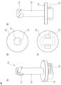
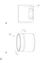

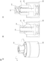
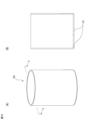



Classifications
-
- A—HUMAN NECESSITIES
- A45—HAND OR TRAVELLING ARTICLES
- A45D—HAIRDRESSING OR SHAVING EQUIPMENT; EQUIPMENT FOR COSMETICS OR COSMETIC TREATMENTS, e.g. FOR MANICURING OR PEDICURING
- A45D40/00—Casings or accessories specially adapted for storing or handling solid or pasty toiletry or cosmetic substances, e.g. shaving soaps or lipsticks
- A45D40/02—Casings wherein movement of the lipstick or like solid is a sliding movement
- A45D40/04—Casings wherein movement of the lipstick or like solid is a sliding movement effected by a screw
-
- A—HUMAN NECESSITIES
- A45—HAND OR TRAVELLING ARTICLES
- A45D—HAIRDRESSING OR SHAVING EQUIPMENT; EQUIPMENT FOR COSMETICS OR COSMETIC TREATMENTS, e.g. FOR MANICURING OR PEDICURING
- A45D40/00—Casings or accessories specially adapted for storing or handling solid or pasty toiletry or cosmetic substances, e.g. shaving soaps or lipsticks
- A45D40/16—Refill sticks; Moulding devices for producing sticks
Definitions
- the present invention relates to a delivery container, particularly to a delivery container used for storing lipstick and the like.
- Containers for storing lipstick and the like, feeding them when used, and returning them after use are well known.
- a container body comprising a helical cylinder formed with a helical hole extending in the circumferential direction and a regulating cylinder rotatably attached to the helical cylinder; a storage tube portion disposed inside the container body and in which a rod-shaped content is stored;
- the accommodating tube portion has a guided protrusion inserted into the spiral hole and the guide hole, and the guided protrusion is engaged with the guide hole, thereby allowing the accommodating tube portion and the restricting tube to move relative to each other.
- target rotation is restricted
- Patent Document 1 The container described in Patent Document 1 is assumed to be discarded after the contents have been used up.
- a feeding container has been proposed that has a cartridge (refill) that stores the contents, and after the contents are used up, the cartridge part is discarded, but the parts other than the cartridge can be reused.
- a cylindrical main member having a first threaded groove on its inner peripheral surface; a tubular sub-member attached to the main member by erecting a sleeve tube having a vertical slit inside the main member from the inside of a base tube portion arranged below the main member; a containing body for containing a content fitted in the sleeve so as to be able to move up and down; the base cylinder portion and the main member are integrally rotatable with respect to the sleeve portion;
- a second screw groove portion that forms a series of spiral grooves continuously with the first screw groove portion is provided on the inner surface of the base cylinder portion, The base cylinder portion and the main member are rotated with respect to the sleeve portion by a delivery mechanism in which an engaging projection attached to the outer surface of the container is protruded into the spiral groove through the vertical slit.
- Operation allows the container to be extended upward and retracted downward within the sleeve, the secondary member and the containing body are formed as a single cartridge assembled to the main member,
- a dispensing container is disclosed in which the cartridge can be pulled out from the main member and replaced with the engaging projection in the second screw groove.
- Such a feeding container has the advantage that the parts other than the cartridge can be reused after the contents are used up, and when using different types of contents (for example, when using different colors of lipstick) There is also the advantage that one part can be owned and used by replacing the cartridge containing the desired contents each time.
- JP 2018-186989 A Japanese Patent Application Laid-Open No. 2021-029940
- the cost of the cartridge portion is high because the delivery mechanism, which is the main mechanism of the container, is formed in the cartridge portion. Nevertheless, since the cartridge portion is discarded after the contents of the container have been used up, the dispensing mechanism is also discarded together with the cartridge portion, which is wasteful.
- the present invention has been made in view of the above circumstances, and an object of the present invention is to provide a dispensing container having a refill for storing contents, a portion other than the refill can be reused, and a dispensing mechanism that can be reused.
- a dispensing container which is formed in parts.
- the present invention is as follows.
- a main body including a middle tool, a middle frame, a screw member, and a hakama, Consists of a refill including a middle plate and a middle cylinder, in the body,
- the middle tool has a key-shaped protrusion for fixing the middle plate, and is fitted in the middle frame so as to be vertically immovable and not relatively rotatable
- the middle frame is inserted into the hakama in a relatively rotatable and non-liftable manner
- the screw member has a screw member screw raceway
- the middle tool has a middle tool screw raceway that is screwed with the screw member screw raceway of the screw member, or a middle tool convex part that can slide on the screw member screw raceway of the screw member,
- the screw member is fixedly attached to the hakama
- the inner plate has a convex portion for fixing the contents and a content storage portion for storing the content, and is fitted in the middle cylinder so as to be vertically non-rotatable and free
- the middle plate is relatively fixed, When the skirt and the middle frame are rotated relative to each other, the middle fitting is fitted in the middle frame such that the screw member screw track of the screw member attached to the skirt is non-rotatable relative to the middle frame.
- the inner tool screw raceway or the inner tool convex part of the inner tool and the inner plate fixed thereto By sliding the inner tool screw raceway or the inner tool convex part of the inner tool and the inner plate fixed thereto, the inner tool and the inner plate fixed thereto can be extended upward and retracted downward. delivery container.
- the middle frame has a projection for fixing the middle cylinder
- the middle cylinder has an L-shaped slit for fixing the middle frame
- the detachable fixation of the middle cylinder to the middle frame is performed by engaging the projection of the middle frame for middle cylinder fixing with the L-shaped slit for fixing the middle frame.
- the middle tool has a protrusion for preventing rotation of the middle tool
- the middle frame has a middle frame vertical slit, By inserting the protrusion for preventing rotation of the middle fitting into the vertical slit of the middle frame, the middle fitting is fitted in the middle frame so as to be vertically immovable and not relatively rotatable.
- the middle tool has a middle tool screw raceway, When the skirt and the middle frame are rotated relative to each other, the inner tool screw track of the inner tool slides on the screw member screw track of the screw member attached to the lower skirt.
- the middle frame has a middle frame fitting portion for setting screw member positions, the screw member has a screw member fitting portion for setting the screw member position, By engaging the screw member position setting middle frame fitting portion of the middle frame with the screw member position setting screw member fitting portion of the screw member, the middle frame is connected to the skirt and the screw member. , held relatively rotatable and non-liftable, A delivery container according to aspect 4.
- the middle tool has a middle tool convex part
- the middle frame has a middle frame vertical slit
- the screw member screw raceway is a female screw raceway
- the convex part of the middle tool of the middle tool is It has a function of being inserted into the middle frame vertical slit of the middle frame and inserting the middle fitting into the middle frame so that it cannot rotate relatively and can be moved up and down, When the skirt and the middle frame are relatively rotated, the screw member attached to the skirt slides along the screw track of the screw member.
- the main body further includes a hook
- the hook has an engaging portion for fixing the middle frame, and is attached to the hakama so as to be relatively rotatable and non-liftable
- the middle frame has a hook fixing engaging portion, By engaging the hook fixing engaging portion of the middle frame with the middle frame fixing engaging portion of the hook, the middle frame can rotate relative to the skirt and the screw member and move up and down. incapacitated,
- ⁇ Aspect 11>> Including a middle plate and a middle cylinder,
- the inner plate has a convex portion for engaging the inner component and a content storage portion, It is fitted in the middle cylinder so that it cannot rotate relatively and can be raised and lowered, Used in the delivery container of aspect 1, Refill for the dispensing container.
- the middle tool has a key-shaped projection for fixing the middle plate, and is fitted in the middle frame so as to be vertically immovable and not relatively rotatable,
- the middle frame is inserted into the inside of the hakama so as to be relatively rotatable and unable to move up and down,
- the screw member has a screw member screw raceway,
- the middle tool has a middle tool screw raceway that is screwed with the screw member screw raceway of the screw member, or a middle tool convex part that can slide on the screw member screw raceway of the screw member,
- the screw member is fixedly attached to the hakama, Used in the delivery container of aspect 1, The body of the dispensing container.
- a dispensing container which has a refill for storing contents, and after the contents are used up, the refill part is discarded, but the parts other than the refill can be reused, and the dispensing mechanism can be reused.
- a dispensing container is provided that is formed in parts and reduces waste.
- the delivery container of the present invention can be used even when a user who owns a plurality of types of contents has a portion other than a refill, for example, only one, and replaces the refill containing the desired contents each time. It also has the advantage of reducing waste.
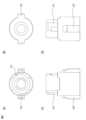
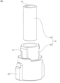
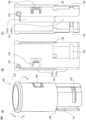
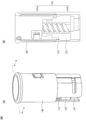
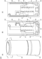
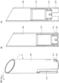
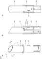
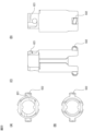
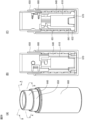
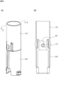
- FIG. 1(A) is a perspective view of a filling in the main body of the dispensing container of Embodiment 1
- FIG. 1(B) is a cross-sectional view taken along the line AA of FIG. 1(A).
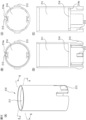
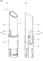
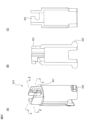
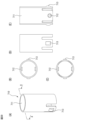
- FIG. 2(A) is a top view of a filling in the main body of the feeding container of Embodiment 1
- FIG. 2(B) is a bottom view
- FIG. 2(C) is a front view
- FIG. ) is a right side view.
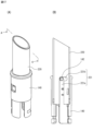
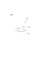
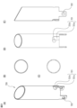
- FIG. 3 is a perspective view of the outer peripheral portion of the inner component and the inner threaded portion of the inner component that constitute the inner component in the main body of the delivery container of the first embodiment.
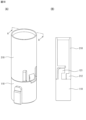
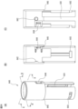
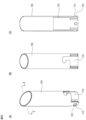
- FIG. 4(A) is a perspective view of the middle frame in the main body of the delivery container of Embodiment 1
- FIG. 4(B) is a cross-sectional view along line AA of FIG. 4(A)
- FIG. ) is a cross-sectional view taken along line BB of FIG. 4(A).
- 5(A) is a perspective view of the inner frame and inner fittings in the main body of the delivery container of Embodiment 1
- FIG. 5(B) is a cross-sectional view taken along the line AA of FIG. 5(A).
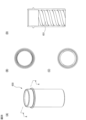
- 6(A) is a perspective view of a screw member in the main body of the feeding container of Embodiment 1
- FIG. 6(B) is a top view
- FIG. 6(C) is a bottom view
- FIG. 7(A) is a perspective view of the hakama in the main body of the delivery container of Embodiment 1
- FIG. 7(B) is a cross-sectional view taken along the line AA of FIG. 7(A).
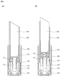
- 8(A) is a perspective view of the skirt and the screw member in the main body of the dispensing container of Embodiment 1
- FIG. 8(B) is a cross-sectional view taken along line AA of FIG. 8(A).
- 9(A) is a perspective view of the skirt, screw members, and inner fittings in the main body of the delivery container of Embodiment 1
- FIG. 9(B) is a cross-sectional view taken along the line AA of FIG. 9(A). be.
- FIG.9(C) is sectional drawing which shows the state which rotated the hakama, the screw member, and the inner fitting relatively from the state of FIG.9(B), and raised the inner fitting a little.
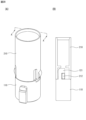
- 10(A) is a perspective view of the outer cylinder in the main body of the feeding container of Embodiment 1
- FIG. 10(B) is a cross-sectional view taken along line AA of FIG. 10(A).
- FIG. 11(A) is a perspective view of the main body of the delivery container of Embodiment 1
- FIG. 11(B) is a cross-sectional view along line AA of FIG. 11(A)
- FIG. FIG. 11(A) is a cross-sectional view taken along line BB of FIG.
- FIG. 11(A); 12(A) is a perspective view of the middle plate in the refill of the delivery container of Embodiment 1
- FIG. 12(B) is a top view of the middle plate
- FIG. 12(C) is a bottom view of the middle plate.
- 12(D) is a cross-sectional view taken along the line AA of FIG. 12(A)
- FIG. 12(E) is a cross-sectional view taken along the line BB of FIG. 12(A).
- FIG. 13(A) is a perspective view showing a state in which lipstick, which is the content, is stored in the middle plate of the refill container of Embodiment 1, and FIG. It is an A line sectional view.
- FIG. 14(A) is a perspective view of the middle cylinder in the refill of the delivery container of Embodiment 1
- FIG. 14(B) is a top view of the middle cylinder
- FIG. 14(C) is a bottom view of the middle cylinder.
- FIG. 14(D) is a front view of the middle cylinder.
- 15(A) is a perspective view of the inner plate and the inner cylinder in the refill of the delivery container of Embodiment 1
- FIG. 15(B) is a cross-sectional view taken along line AA of FIG. 15(A).
- FIG. 15(C) is a cross-sectional view showing a state in which the inner plate is slightly raised from the state of FIG. 15(B).
- FIG. 16(A) is a perspective view showing only the inner frame of the main body and the inner cylinder of the refill when the refill is being inserted into the main body of the dispensing container of Embodiment 1, and FIG. 16(B). ) is a sectional view taken along the line AA of FIG. 16(A).
- FIG. 17(A) is a perspective view showing only the inner frame of the main body and the inner cylinder of the refill in a state immediately before the refill is inserted into the main body of the dispensing container of Embodiment 1 and assembled.
- B) is a cross-sectional view taken along the line AA of FIG. 17(A).
- FIG. 18(A) is a perspective view showing only the inner part of the main body and the inner plate of the refill in a state immediately before the refill is inserted into the main body of the dispensing container of Embodiment 1 and assembled.
- B) is a sectional view taken along the line AA of FIG. 18(A).
- FIG. 19(A) is a perspective view showing only the inner frame of the main body and the inner cylinder of the refill when the refill is inserted into the main body of the dispensing container of Embodiment 1 and assembled
- FIG. ) is a cross-sectional view taken along the line AA of FIG. 19A
- FIG. 19C is a cross-sectional view taken along the line BB of FIG. 19A.
- FIG. 20(A) is a perspective view showing only the inner part of the main body and the inner plate of the refill when the refill is inserted into the main body of the delivery container of Embodiment 1 and assembled, and FIG. ) is a sectional view taken along the line AA of FIG. 20(A).
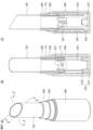
- FIG. 21(A) is a cross-sectional view showing a state before delivery of the delivery container of Embodiment 1.
- FIG. 21(B) is a cross-sectional view showing a state in which the contents are slightly drawn out from the state shown in FIG. 21(A).
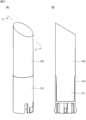
- FIG. 22(A) is a perspective view of a filling in the main body of the delivery container of Embodiment 2
- FIG. 22(B) is a cross-sectional view along line AA of FIG.
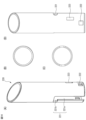
- Fig. 23(A) is a top view of a filling in the main body of the delivery container of Embodiment 2
- Fig. 23(B) is a bottom view
- Fig. 23(C) is a front view
- Fig. 23(D) is a bottom view.
- ) is a right side view.
- 24(A) is a perspective view of the middle frame in the main body of the delivery container of Embodiment 2
- FIG. 24(B) is a cross-sectional view along line AA of FIG. ) is a cross-sectional view taken along line BB of FIG. 24(A).
- FIG. 25 is a perspective view of a hook in the main body of the dispensing container of Embodiment 2.
- FIG. FIG. 26(A) is a perspective view of the inner fitting, the middle frame, and the hook in the main body of the delivery container of Embodiment 2
- FIG. 26(B) is a cross-sectional view taken along line AA of FIG.
- FIG. 26(C) is a cross-sectional view taken along line BB of FIG. 26(A).
- 27(A) is a perspective view of a hakama in the main body of the delivery container of Embodiment 2
- FIG. 27(B) is a top view
- FIG. 27(C) is a bottom view
- FIG. 27(D) is a perspective view of a hook in the main body of the dispensing container of Embodiment 2.
- FIG. FIG. 26(A) is a perspective view of the inner fitting, the middle frame, and the hook in the main body of the delivery container of Embodiment 2
- FIG. 27(A) is a cross-sectional view taken along line AA of FIG. 27(A).
- 28(A) is a perspective view of a screw member in the main body of the delivery container of Embodiment 2
- FIG. 28(B) is a top view
- FIG. 28(C) is a bottom view
- FIG. ) is a sectional view taken along the line AA of FIG. 28(A).
- Fig. 29(A) is a perspective view of the inner fitting, middle frame, hook, screw member, and hakama in the main body of the feeding container of Embodiment 2
- Fig. 29(B) is A of Fig. 29(A) 29(C) is a cross-sectional view taken along the line BB of FIG. 29(A).
- Fig. 29(A) is a perspective view of a screw member in the main body of the delivery container of Embodiment 2
- Fig. 29(B) is A of Fig. 29(A) 29(C) is
- FIG. 30(A) is a perspective view of an inner plate in the refill of the delivery container of Embodiment 2
- Fig. 30(B) is a top view
- Fig. 30(C) is a bottom view
- Fig. 30(D) is a top view.
- ) is a front view
- FIG. 30(E) is a sectional view taken along line AA of FIG. 30(A).
- Fig. 31(A) is a perspective view of a middle cylinder in the refill of the delivery container of Embodiment 2
- Fig. 31(B) is a top view
- Fig. 31(C) is a bottom view
- Fig. 31(D) is a top view.
- ) is a front view
- FIG. 31(E) is a right side view.
- FIG. 32(A) is a perspective view of a middle plate and a middle cylinder in the refill of the delivery container of Embodiment 2
- Fig. 32(B) is a front view
- Fig. 32(C) is Fig. 32(A).
- 1 is a cross-sectional view taken along line AA of FIG.
- FIG. 33(A) is a perspective view showing only the inner frame of the main body and the inner cylinder of the refill when the refill is inserted into the main body of the dispensing container of Embodiment 2 and assembled
- FIG. ) is a sectional view taken along the line AA of FIG. 33(A).
- FIG. 34(A) is a perspective view showing only the inner part of the main body and the inner plate of the refill when the refill is inserted into the main body of the dispensing container of Embodiment 2 and assembled, and FIG. ) is a sectional view taken along the line AA of FIG. 34(A).
- FIG. 35(A) is a perspective view showing the entire lifting container of Embodiment 2
- FIG. 35(B) is a cross-sectional view along line AA of FIG. 35(A)
- FIG. and a cross-sectional view taken along the line BB of FIG. 35(A).
- the delivery container of the present invention is a main body including a middle fitting, a middle frame, a screw member, and a hakama; It is composed of a refill including a middle plate and a middle cylinder.
- the dispensing container of the present invention may further include a tail plug.
- the middle tool has a key-shaped protrusion for fixing the middle plate, and is fitted in the middle frame so as to be vertically immovable and not relatively rotatable,
- the middle frame is inserted into the hakama in a relatively rotatable and non-liftable manner
- the screw member has a screw member screw raceway
- the middle tool has a middle tool screw raceway that is screwed with the screw member screw raceway of the screw member, or a middle tool convex part that can slide on the screw member screw raceway of the screw member,
- the screw member is fixedly attached to the hakama.
- the middle plate has a convex portion for fixing the inner component and a content storage portion for storing the content, and is fitted in the middle cylinder so as to be vertically non-rotatable and free to move up and down,
- the refill can be detachably attached to the main body, and
- the key-shaped convex portion for fixing the inner plate of the inner container and the convex portion for fixing the inner plate of the inner plate are engaged with each other, thereby The middle plate is relatively fixed.
- the screw member screw trajectory of the screw member attached to the skirt cannot be relatively rotated inside the middle frame.
- the contents stored in the delivery container of the present invention may be solid rod-shaped medicines, quasi-drugs, cosmetics, and the like.
- the content may be, for example, lipstick, lip balm, eye shadow, eyebrow (eyebrow), cheek (blusher), concealer, foundation, etc., and typically lipstick.
- the delivery container of the present invention can also be applied as a solid stick-shaped stationery container.
- stationery include erasers, glue, crayons, and pastels.
- the main body includes a middle fitting, a middle frame, a screw member, and a hakama.
- the middle tool may have a substantially cylindrical shape, and has a key-shaped projection for fixing the middle plate, a screw raceway for the middle tool or a projection for the middle tool, and further a projection for preventing rotation of the middle tool, It may have vertical slits or the like.
- the key-shaped convex portion for fixing the inner plate engages with the convex portion for fixing the inner component of the inner plate of the refill, so that the inner container and the inner plate are relatively fixed. It has the function of fixing to
- the key-shaped convex portion for fixing the inner plate is, for example, an inverted L-shaped relief-like protrusion formed on a portion of the outer peripheral surface of the cylindrical inner member near the upper end, or an upper end of the cylindrical inner member. It may be an inverted L-shaped protrusion or the like that protrudes upward from the circumference of the .
- the term "inverted L-shape" refers to a shape composed of a linear portion extending upward and a linear portion extending in the circumferential direction from the upper end of the linear portion.
- the inner part may have only one key-shaped protrusion for fixing the inner plate, or may have two or more.
- these key-shaped protrusions for fixing the inner plate are arranged on the outer peripheral surface of the cylindrical inner component or on the circumference near the upper end, They may be evenly distributed along the circumference.
- the inner fitting in the main body of the dispensing container of the present invention typically has 2 or more and 4 or less key-like protrusions for fixing the inner plate.
- the inner piece screw raceway is screwed with the screw raceway of the screw member, and when the middle piece and the screw member are rotated relatively, the middle piece (and the middle plate fixed relatively to the middle piece) with respect to the screw member (and the inner frame and the hakama relatively fixed thereto).
- the inner screw raceway may be either a male screw or a female screw as long as it can be screwed with the screw member screw raceway of the screw member.
- the inner component screw track may be, for example, a female thread formed on the inner peripheral surface of the cylindrical inner component.
- the convex part of the inner tool is a convex part that can slide along the screw track of the screw member, and when the inner tool and the screw member are rotated relatively, It has a function to raise and lower the inner plate) with respect to the screw member (and the inner frame and the hakama relatively fixed thereto).
- the central tool protrusion may be formed anywhere on the inner tool.
- the inner tool protrusion may be, for example, one or two or more protrusions formed on the outer peripheral surface of the cylindrical inner tool.
- the shape of the convex portion of the middle tool is arbitrary as long as it can slide along the screw track of the screw member.
- the inner component may have only one inner component convex portion, or may have two or more.
- these inner tool protrusions may be evenly arranged along the circumference on the inner peripheral surface or the outer peripheral surface of the cylindrical inner tool.
- the number of the inner component protrusions may typically be 2 or more and 4 or less.
- the inner component of the delivery container of the present invention may selectively have the inner component screw raceway and the inner component convex portion according to the aspect of the screw member screw raceway possessed by the screw member.
- the inner fitting when the screw member screw raceway is a male screw, the inner fitting has a female screw-like inner fitting screw raceway formed on the inner peripheral surface of the cylindrical inner fitting and the inner peripheral surface of the cylindrical inner fitting. It may have one or more of the midpiece projections that are projections formed.
- the inner fitting may have a inner fitting convex portion which is a projection formed on the outer peripheral surface of the cylindrical inner fitting.
- the contents of the dispensing container of the present invention may have a protrusion for preventing rotation of the contents.
- the middle fitting rotation preventing convex portion may be fitted into a middle frame vertical slit that the middle frame optionally has when the middle fitting is fitted into the middle frame. With this configuration, the middle fitting is fitted in the middle frame so as to be relatively non-rotatable and vertically movable.
- the protrusion for preventing rotation of the inner member may be a protrusion formed on the outer peripheral surface of the cylindrical inner member.
- the shape of the protruding part for preventing the rotation of the middle frame should be wide enough to fit in the middle frame vertical slit, protruding height, and length enough to allow smooth lifting in the middle frame vertical slit. and the rest of the shape may be arbitrary.
- the inner tool may have only one protrusion for preventing rotation of the inner tool, or may have two or more.
- these protrusions for preventing rotation of the inner member are arranged evenly along the circumference on the outer peripheral surface of the cylindrical inner member. good.
- the number of protrusions may be typically 2 or more and 4 or less.
- the protrusion may also function as a protrusion for preventing rotation of the inner tool.
- the convex part of the inner part protrudes from the outer surface of the inner frame in a state of being fitted in the longitudinal slit of the inner frame, and slides along the threaded track of the screw member, which is a female screw.
- the middle tool may be integrally formed, or may be configured by combining two or more parts.
- the inner fitting may be composed of, for example, two large and small tubular parts, the outer peripheral portion of the inner fitting and the inner threaded portion of the inner fitting.
- the outer peripheral portion of the inner component may have a key-shaped protrusion for fixing the inner plate and a protrusion for preventing rotation of the inner component on its outer peripheral surface. It may have a trajectory.
- the inner component vertical slit is a vertical notch formed on the outer surface of the cylindrical inner component.
- the inner fitting in the main body of the delivery container of the present invention may or may not have this inner fitting vertical slit.
- ⁇ middle frame> The middle frame in the main body of the dispensing container of the present invention is inserted into the hakama in such a manner that it is relatively rotatable and cannot move up and down.
- the middle frame may have a substantially cylindrical shape, and includes a middle frame vertical slit, a projection for fixing the middle cylinder, a middle frame fitting portion for setting the position of the screw member, an engaging portion for fixing the hook, and an anti-rotation portion for the middle cylinder. It may have an intermediate frame claw or the like.
- the middle frame vertical slit of the middle frame is fitted with the projection for preventing rotation of the middle piece when the middle piece is inserted into the middle frame. It has a function to control so that it cannot rotate and can be raised and lowered.
- the middle frame vertical slit may be a linear slit extending upward from the lower end of the cylindrical middle frame.
- the width of the middle frame vertical slit may be a width that allows fitting of the projection for preventing rotation of the middle piece of the middle piece and enables smooth lifting and lowering.
- the length of the middle frame vertical slit defines the length of elevation of the inner component, the inner plate fixedly mounted thereon, and the contents stored in the inner plate. Therefore, the length of the middle frame vertical slit may be substantially the same as the length of delivery of the contents.
- the middle frame vertical slit may be formed by cutting out a part of the peripheral wall of the middle frame into a predetermined shape, and the middle frame vertical slit part may have a penetrating form in which there is no peripheral wall, or the inner circumference of the peripheral wall of the middle frame
- a part of the surface may be thinned to a predetermined shape to form a thin-walled form in which the inner frame vertical slit portion of the inner frame also has a peripheral wall, or a part of the inner frame vertical slit portion of the inner frame may have a peripheral wall. It is also possible to adopt a through-hole form in which the inner frame has a thin-walled form, and the rest of the inner-frame vertical slit portion of the inner frame has a peripheral wall.
- the middle frame in the main body of the dispensing container of the present invention has the same number of vertical slits in the middle frame as the projections for preventing rotation of the middle fitting, at locations corresponding to the projections for preventing rotation of the middle fitting. you can
- the convex part for fixing the middle cylinder of the middle frame engages with the L-shaped slit for fixing the middle frame arbitrarily provided in the middle cylinder of the refill, and the middle cylinder is attached to the middle frame. It has a detachable fixing function. With this function, a refill can be detachably attached to the main body of the dispensing container of the present invention.
- the middle cylinder fixing convex portion may be a projection formed on a portion of the inner peripheral surface of the cylindrical middle frame near the upper end. If the convex portion for fixing the middle cylinder can slide vertically in the L-shaped slit for fixing the middle frame of the middle cylinder and can engage with the L-shaped slit for fixing the middle frame in the horizontal direction, It may have any shape.
- the middle cylinder fixing projection may be, for example, a hemispherical projection.
- the middle frame may have only one projection for fixing the middle cylinder, or may have two or more.
- these middle cylinder fixing projections may be arranged evenly along the circumference on the inner peripheral surface of the cylindrical middle frame.
- the number of projections may be typically two or more and four or less.
- the screw member position setting middle frame fitting portion receives the screw member position setting screw member fitting portion arbitrarily possessed by the screw member, and attaches the middle frame to the screw member (and this is fixedly mounted). It has a function to hold it so that it can rotate relative to the hakama) and cannot move up and down.
- the screw member position setting middle frame fitting portion may be a slit extending in the circumferential direction formed in a portion of the peripheral wall of the cylindrical middle frame near the lower end.
- the screw member position setting middle frame fitting portion has a configuration in which a part of the peripheral wall of the middle frame is cut out in a predetermined shape, and the portion of the middle frame where the screw member position setting middle frame fitting portion does not have a peripheral wall.
- a part of the inner peripheral surface of the peripheral wall of the intermediate frame may be thinned to a predetermined shape, and the peripheral wall may also be provided in the portion of the intermediate frame fitting portion for setting the screw member position of the intermediate frame.
- a configuration in which a part of the screw member position setting middle frame fitting portion of the middle frame does not have a peripheral wall, and the remaining portion of the screw member position setting middle frame fitting portion of the middle frame has a peripheral wall. may be
- the middle frame may have only one middle frame fitting portion for setting the screw member position, or may have two or more.
- these screw member position setting middle frame fitting portions are arranged along the circumference on the peripheral wall of the cylindrical middle frame. may be evenly distributed.
- the middle frame in the main body of the dispensing container of the present invention has the screw member position setting middle frame fitting portions, the number thereof may typically be two or more and four or less.
- the hook fixing engaging portion engages with the middle frame fixing engaging portion of the hook optionally possessed by the main body of the dispensing container of the present invention, and inserts the inner tool into the space formed by the middle frame and the hook.
- relatively non-rotatable and has a function of being able to move up and down.
- the middle frame is relatively rotatable with respect to the screw member fixedly attached to the hakama. It is held so that it cannot move up and down.
- the hook-fixing engaging portion may be a recessed portion or a slit extending in the circumferential direction formed in a portion of the peripheral wall of the cylindrical inner frame near the lower end.
- the middle frame may have only one hook fixing engaging portion, or may have two or more.
- these hook fixing engaging portions may be evenly arranged along the circumference on the peripheral wall of the cylindrical middle frame.
- the middle frame in the main body of the delivery container of the present invention has hook fixing engaging portions, the number thereof may be typically two or more and four or less.
- the middle frame may have both the screw member position setting middle frame fitting portion and the hook fixing engaging portion.
- the screw member position setting middle frame fitting portion and the hook fixing engaging portion It is sufficient to have either one.
- the middle frame has the hook fixing engaging portion and does not have the screw member position setting middle frame fitting portion, it is desirable that the main body of the dispensing container has the hook.
- the middle-cylinder-rotation-preventing middle-frame claw portion is the middle-cylinder-rotation-preventing middle-cylinder engaging portion (or the middle-frame-fixing L-shaped slit that also serves this function) that the middle cylinder of the refill container of the present invention optionally has. and has a function of suppressing relative rotation between the middle cylinder and the middle frame.
- the middle cylinder and the middle frame do not rotate relative to each other when the skirt and the middle frame are rotated relative to each other, and the inner fittings, etc. are extended upward and downward. It is possible to efficiently and smoothly carry out upward delivery and downward delivery of the inner fitting fitted in the frame so as not to rotate relative to it, and the inner plate fixed thereto.
- the claw portion of the middle frame for preventing rotation of the middle cylinder may be a flexible claw-like projection formed on the peripheral wall near the middle in the axial direction of the cylindrical middle frame. Specifically, for example, near the tip of the " ⁇ (pi)"-shaped notch (horizontal line above the letter “ ⁇ ") formed on the peripheral wall of the cylindrical middle frame, inside the middle frame It may be in the form of having projections projecting toward it.
- the middle frame may have only one middle-cylinder rotation-preventing middle-frame claw portion, or may have two or more.
- these middle-cylinder-rotation-preventing middle-frame claws are arranged evenly along the circumference on the peripheral wall of the cylindrical middle frame. may be placed in
- the middle frame in the main body of the delivery container of the present invention has middle frame claws for preventing rotation of the middle cylinder, the number thereof may be typically two or more and four or less.
- the screw member in the main body of the delivery container of the present invention is fixedly attached to the hakama.
- the screw member has a screw member screw track, and may have a screw member fitting portion for screw member position setting, a screw member engaging portion for fixing screw member, and the like.
- the middle fitting is inserted into the middle frame so that it cannot relatively rotate and can be moved up and down. Further, when the refill is attached to the main body of the feeding container of the present invention, the key-shaped convex portion for fixing the inner plate of the inner container and the convex portion for fixing the inner plate of the inner plate are engaged with each other, so that the inner container is attached to the refill. is fixed relative to the middle plate of the
- the middle tool screw track or the middle tool protrusion slides on the screw track of the screw member attached to the skirt.
- the inner component and the inner plate fixed thereto can be extended upward and retracted downward.
- the screw member screw trajectory may be a male screw or a female screw.
- the screw member When the screw member screw track is a male screw, the screw member includes a disk-shaped screw member position setting screw member fitting portion and a screw shaft extending upward from the center of the screw member position setting screw member fitting portion. and a screw member screw raceway formed on the outer peripheral surface of the screw shaft.
- the screw member position setting screw member fitting portion is inserted into the screw member position setting middle frame fitting portion of the middle frame, and the middle frame is attached to the screw member (and the skirt which is fixedly held). It has a function of holding it relatively rotatably and unable to move up and down.
- the screw member position setting screw member fitting portion has a diameter and thickness that allows it to be inserted into the screw member position setting middle frame fitting portion of the middle frame and rotate smoothly.
- the screw shaft may be a rod-shaped body extending upward from the center of the screw member fitting portion for setting the screw member position.
- the length of this screw shaft defines the length of elevation of the inner tool, the inner plate fixedly mounted thereon, and the contents stored in the inner plate. Therefore, the length of the screw shaft may be approximately the same as the delivery length of the contents.
- the screw shaft is designed so that the threaded member screw track formed on the outer surface thereof is screwed with the inner component threaded track of the inner component to raise and lower the inner component. Therefore, the screw shaft may have a thickness capable of forming a screw raceway having such a function.
- the screw member screw raceway which is a male screw, has the function of screwing with the internal screw raceway of the internal component, which is a female screw, to raise and lower the internal component.
- the screw member screw raceway may be formed over the entire length of the screw shaft, or may be formed over only a portion of the length of the screw shaft.
- the screw member screw track may be a continuous screw track, or may be interrupted in the middle as long as it can be screwed with the inner tool screw track of the inner tool.
- the screw member fixing screw member engaging portion has a function of engaging with the screw member fixing hakama engaging portion of the hakama to securely attach the screw member to the hakama.
- the screw member engaging portion for fixing the screw member may be provided on the screw member when the screw member screw track is a male screw.
- the screw member engaging portion for fixing the screw member may be, for example, a key-shaped projection formed on the bottom surface of the screw member fitting portion for setting the screw member position.
- the screw member may have only one screw member engaging portion for fixing the screw member, or may have two or more.
- these screw member-fixing screw member-engaging portions are provided on the bottom surface of the disc-shaped screw member position setting screw member fitting portion. They may be evenly arranged so as to be point symmetrical.
- the number thereof may be typically two or more and four or less.
- the screw member screw raceway is a female screw
- the screw member may have a cylindrical shape, and the screw member screw raceway may be formed on the inner peripheral surface of the cylindrical screw member.
- the screw track which is a female screw, has the function of raising and lowering the inner fitting by sliding the convex part of the inner fitting on it.
- the screw member screw raceway may be formed over the entire axial length of the screw member, or may be formed over only a portion of the axial length of the screw member.
- the screw member screw trajectory may be a continuous screw trajectory, or it may be interrupted in the middle as long as the inner tool convex portion of the inner tool can slide on it.
- the hakama is located at the bottom of the delivery container of the present invention, and has a function to fixably attach the screw member so that the user can easily operate to rotate the screw member relative to the middle tool. .
- the hakama may have a cylindrical shape with a bottom.
- the hakama may have, for example, a hakama engaging portion for fixing the screw member in order to securely attach the screw member.
- This screw member fixing skirt engaging portion is intended to engage with the screw member fixing screw member engaging portion of the screw member to exhibit the above function. Therefore, the screw member fixing skirt engaging portion may be, for example, a key-shaped protrusion formed on the inner side of the bottom surface.
- the skirt may have the same number of screw member-fixing skirt engaging portions as the screw member-fixing screw member engaging portions of the screw member, at positions corresponding to the respective screw member-fixing screw member engaging portions.
- the hooks may be used to hold the inner fitting in the space defined by the middle frame and the hooks so that they cannot rotate relative to each other and can move up and down.
- the hook may have a disk-shaped hook substrate and an engaging portion for fixing the middle frame formed on the hook substrate.
- This middle frame fixing engaging portion engages with the hook fixing engaging portion of the middle frame, and has a function of making the space formed by the middle frame and the hook permanent. Therefore, the middle frame fixing engaging portion may be a key-shaped protrusion that protrudes upward from the hook base plate and can be engaged with the hook fixing engaging portion of the middle frame.
- the hook may have the same number of middle frame fixing engaging portions as the hook fixing engaging portions of the middle frame at positions corresponding to the respective middle frame fixing engaging portions.
- the hook may be attached to the hakama relatively rotatably and not up and down.
- the set of the hakama and the screw member can rotate relative to the set of the middle frame and the hook, but cannot move up and down.
- the inner tool screw raceway or inner tool convex portion of the inner tool held so as not to rotate slides on the screw member screw track, and the inner tool and the inner plate fixed thereto are paid out upward and downward. It is possible to loop back to
- the delivery container of the present invention may have an outer cylinder.
- the outer cylinder surrounds the outer peripheral surface of the middle frame, and has the function of facilitating the operation of rotating the middle frame relative to the hakama (and the screw member fixedly attached thereto) by the user. have.
- the outer cylinder may have a tubular shape that can surround the outer peripheral surface of the middle frame, and the middle frame may be fixedly inserted into the outer cylinder.
- the refill for the delivery container of the present invention includes a middle plate and a middle cylinder.
- the refill may further have a temporary stopper.
- the middle plate may have a substantially cylindrical shape, has a content storage portion and a projection for fixing the middle plate, and further includes a middle plate engaging portion for preventing rotation of the middle plate, a middle plate partition step, and a content. It may have an object-fixing protrusion or the like.
- the content storage part is a space for storing and holding the lower end of the stick-shaped content (eg, lipstick).
- the upper end of the content projects upward from the content storage section and is exposed.
- the middle plate may have a middle plate partition step.
- the inner space of the cylindrical inner plate may be divided into upper and lower parts by the inner plate partition step, and the space above the inner plate partition step in the inner space of the inner plate may be the content storage section.
- the middle plate partition stage may have one or more air vent holes for filling contents. This content-filling air vent hole is a hole penetrating the middle plate partition step, and when the middle plate is filled with content, the air in the lower part of the content-storing portion is released to the outside of the content-filling portion, and the content is stored. It has a function to make it easier to fill the part with contents.
- the inner plate may further have a content-fixing convex portion that protrudes inward (toward the content storage portion) from the inner peripheral surface of the inner peripheral wall of the inner plate.
- the content-fixing convex portion has a function of biting into the content filled in the content-accommodating portion and suppressing relative movement between the content and the inner tray.
- the convex part for fixing the inner component engages with the key-shaped convex part for fixing the inner plate of the inner component of the main body, thereby holding the inner component and the inner plate relative to each other. It has the function of fixing to
- the inner fixture fixing protrusion may be a relief-like protrusion formed on a portion of the outer peripheral surface of the cylindrical inner plate near the lower end.
- the shape of the projection for fixing the inner component is arbitrary as long as it can engage with the key-like projection for fixing the inner plate of the inner component, and may be, for example, a rectangular or hemispherical protrusion.
- the rotation-preventing middle-plate engaging portion engages with the middle-plate rotation-preventing middle-cylinder engaging portion of the middle cylinder, and the middle plate and the middle cylinder are kept relatively apart until the refill is attached to the main body. It has a fixing function.
- the middle plate is fixed to the middle piece of the main body via the middle piece fixing convex portion and the middle plate fixing key-shaped convex portion, and the middle cylinder is fixed to the middle frame fixing portion. It is fixed to the middle frame of the main body via the L-shaped slit and the projection for fixing the middle frame. Therefore, after the refill is attached to the main body, the practical benefit of directly fixing the inner plate and the inner container is reduced.
- the middle plate is expected to move vertically with respect to the middle cylinder to be delivered or returned. Therefore, it is desired that the fixation between the inner plate and the inner fitting is temporary.
- the middle plate engaging portion for preventing rotation of the middle plate is surrounded by, for example, two cuts formed in a portion near the lower end of the outer peripheral surface of the cylindrical middle plate so that the radius of the middle plate is reduced. It may be a protrusion formed in a directionally flexible region.
- the middle plate may have only one key-shaped protrusion for fixing the middle plate, or may have two or more.
- these middle plate rotation-preventing middle plate engaging portions are arranged on the circumference of the outer peripheral surface of the cylindrical middle plate. They may be evenly distributed along the circumference.
- the middle plate in the main body of the dispensing container of the present invention typically has two or more and four or less middle plate fixing key-shaped protrusions.
- the inner plate is fitted in the middle cylinder so as to be relatively non-rotatable and vertically movable.
- the middle cylinder has a substantially cylindrical shape, has an L-shaped slit for fixing the middle frame, and has a middle cylinder engaging portion for preventing rotation of the middle plate, a middle cylinder engaging portion for preventing rotation of the middle cylinder, and the like.
- the middle cylinder has a substantially cylindrical shape.
- This cylindrical shape may have a shape with an obliquely cut upper end. This configuration improves the feeling of use when the content is, for example, lipstick.
- the L-shaped slit for fixing the middle frame engages with the convex part for fixing the middle cylinder which the middle frame of the main body optionally has, so that the middle cylinder can be detachably attached to the middle frame. It has a fixing function. With this function, a refill can be detachably attached to the main body of the dispensing container of the present invention.
- the L-shaped slit for fixing the middle frame is an L-shaped slit consisting of a linear vertical cut portion extending upward from the lower end of the middle cylinder and a linear horizontal cut portion extending in the circumferential direction from the upper end of the vertical cut portion. It may be a notch.
- the convex part for fixing the inner cylinder of the inner frame slides upward from the bottom in the vertical cut part of the L-shaped slit for fixing the inner frame of the inner cylinder.
- the convex part for fixing the middle cylinder reaches the upper end of the vertical cut part of the L-shaped slit for fixing the middle frame, by rotating the refill and the main body relatively, the convex part for fixing the middle cylinder is fixed to the middle frame.
- the middle cylinder is fixed to the middle frame by entering and engaging with the lateral cut portion of the L-shaped slit.
- the middle cylinder in the refill of the feeding container of the present invention has the same number of middle frame fixing L-shaped slits as the middle cylinder fixing projections of the middle frame at locations corresponding to the middle cylinder fixing projections. It's okay.
- the rotation-preventing middle-cylinder engaging portion of the middle plate engages with the rotation-preventing middle-plate engaging portion of the middle plate, and until the refill is attached to the main body, the middle plate and the middle cylinder are relatively displaced. It has a fixing function.
- the middle plate anti-rotation middle cylinder engaging portion may be, for example, a hole formed in the vicinity of the lower end of the cylindrical middle cylinder.
- the shape and size of the hole may be such that it can be easily engaged with the rotation-preventing middle plate engaging portion of the middle plate and disengaged from the container.
- the middle cylinder in the refill of the dispensing container of the present invention has the same number of middle-plate-rotation-preventing middle-cylinder-engaging portions as the middle-plate-rotation-preventing middle-plate-engaging portions of the middle-plate. It may be provided at a location corresponding to each of the parts.
- the rotation-preventing middle-cylinder engaging portion engages with the middle-cylinder-rotation-preventing middle-frame claw portion optionally possessed by the middle frame in the main body of the dispensing container of the present invention, and thereby the middle cylinder and the middle frame are engaged with each other. It has a function to suppress the rotation. As a result, when the hakama and the inner frame are rotated relative to each other, the inner fitting and the inner plate can be efficiently and smoothly extended upward and downward.
- the rotation-preventing middle-cylinder engagement portion is provided on the peripheral wall of the cylindrical middle frame so as to be reversibly engaged with the middle-cylinder-rotation-preventing middle-claw claw portion of the middle frame in the body of the dispensing container. It may be a formed recess (hole).
- the middle cylinder in the refill of the dispensing container of the present invention has the same number of rotation-preventing middle-cylinder engaging portions as the middle-cylinder rotation-preventing middle-frame claws of the middle frame. You may have it in the place corresponding to each.
- the middle cylinder in the refill of the feeding container of the present invention does not have the middle cylinder rotation preventing middle cylinder engaging portion, and the middle frame fixing L-shaped slit has the function of the middle cylinder rotation preventing middle cylinder engaging portion.
- the L-shaped slit for fixing the middle frame has the function of detachably fixing the middle cylinder to the middle frame and the function of suppressing the rotation of the middle frame.
- the refill of the delivery container of the present invention is used to protect the contents during transportation, during sales exhibition, and after the user purchases it until it is attached to the main body, or when using multiple types of contents properly. It may have a temporary stopper to protect the contents of the unfilled refill.
- This temporary plug may be one or more of a lid shaped to cover the upper part of the middle cylinder and a lid shaped to cover the lower part of the middle cylinder.
- the temporary stopper may be discarded, or it protects the unused contents of the refill when using different kinds of contents. may be stored for
- the dispensing container of the present invention may further include a tail plug in addition to the main body and refill as described above.
- the tail plug has the function of protecting the contents after the user has assembled the refill to the main body and started using the contents. After purchasing a refill with a temporary plug, the user assembles it into the main body to form a delivery container, discards the temporary plug, and attaches the tail plug. At the time of use, the tail plug is removed from the delivery container, and the hakama and the middle frame (or the outer cylinder that fixedly covers the middle frame) are rotated relative to each other to remove the middle fitting and the middle plate fixed thereto, In addition, the contents stored in the middle plate are drawn out and used. After use, the hakama and the inner frame are relatively rotated in opposite directions to return the contents, attach the tail plug, and store until the next use.
- the tail plug may be a tubular body with a ceiling that can cover the middle cylinder.
- the bottom of the tail plug may extend to or near the upper end of the hakama with the refill attached to the main body.
- the refill can be detachably attached to the main body. That is, in the supply container of the present invention, it is possible to easily attach the refill to the main body and remove the refill from the main body.
- the convex portion for fixing the middle cylinder of the middle frame of the refill slides upward from the bottom in the longitudinal cut portion of the L-shaped slit for fixing the middle frame of the middle cylinder of the main body.
- the convex portion for fixing the middle cylinder reaches the upper end of the vertical cut portion of the L-shaped slit for fixing the middle frame, the refill and the main body are relatively rotated, so that the convex portion for fixing the middle cylinder is attached to the middle frame.
- the middle tube is fixed to the middle frame by entering and engaging with the lateral cut portion of the fixing L-shaped slit.
- the key-like convex portion for fixing the inner plate of the inner part of the main body and the inner portion of the refill are engaged.
- the middle piece and the middle plate are fixed relative to each other by engaging with the middle piece fixing convex portion of the plate.
- the middle part and the middle plate fixed thereto are rotated by relatively rotating the hakama and the middle frame (or the outer cylinder that fixedly covers the middle frame), and The contents stored in the middle plate can be delivered and returned.
- a screw member having a screw member screw track is fixedly attached to the hakama.
- a refill inner cylinder is fixedly attached to the inner frame.
- a middle tool having a middle tool screw raceway or a middle tool convex portion is fitted into the middle frame so as to be vertically immovable and not relatively rotatable. Relative rotation is possible between the middle frame and the screw member, but relative elevation is impossible. Therefore, the middle frame and the hakama to which the screw members are fixedly attached are also relatively rotatable but relatively unmovable.
- the middle plate for the refill is fixedly attached to the inner part, and the middle plate contains the rod-shaped contents.
- the screw member fixedly attached to the hakama and the middle frame cannot relatively rotate and move up and down.
- the freely inserted inner fitting rotates relatively.
- the inner tool screw raceway or the inner tool convex portion slides on the screw member screw raceway of the screw member, and the inner tool is relatively relative to the skirt, the screw member, the inner frame, and the inner cylinder. up and down.
- the inner tray fixedly attached to the inner tray also moves up and down together with the inner tray, so that the contents accommodated in the inner tray also move up and down. Therefore, the tip of the content projecting upward from the inner plate is delivered to the upper portion of the intermediate frame and then returned downward.
- the inner plate has a convex portion for engaging the inner component and a content storage portion, It is fitted in the middle cylinder so that it cannot rotate relatively and can be raised and lowered, Used for the delivery container of the present invention, A refill for the dispensing container is provided.
- the middle tool has a key-shaped protrusion for fixing the middle plate, and is fitted in the middle frame so as to be vertically immovable and not relatively rotatable,
- the middle frame is inserted into the hakama in a relatively rotatable and non-liftable manner
- the screw member has a screw member screw raceway
- the middle tool has a middle tool screw raceway that is screwed with the screw member screw raceway of the screw member, or a middle tool convex part that can slide on the screw member screw raceway of the screw member,
- the screw member is fixedly attached to the hakama, Used for the delivery container of the present invention,
- a dispenser body is provided.
- FIG. 1 to 11 relate to the main body
- FIGS. 12 to 15 relate to the refill
- FIGS. 16 to 20 relate to the attachment of the refill to the main body
- FIG. 21 relates to the dispensing mechanism.
- FIG. 1(A) is a perspective view of the inner fitting
- FIG. 1(B) is a sectional view taken along the line AA of FIG. 1(A).
- 2(A) is a top view of the inner fitting
- FIG. 2(B) is a bottom view
- FIG. 2(C) is a front view
- FIG. 2(D) is a right side view.
- the middle tool (110) shown in FIGS. 1 and 2 has a substantially cylindrical shape, and includes a key-shaped projection for fixing the middle plate (121), a middle tool screw track (131), and a middle tool rotation. It has a prevention protrusion (122).
- the key-shaped projection (121) for fixing the inner plate in the inner fitting (110) of FIGS. 1 and 2 is an inverted L-shaped relief formed on the outer peripheral surface of the inner fitting (110) near the upper end. It is a protruding part of the shape.
- the middle tool (110) has two middle plate fixing key-shaped protrusions (121) at positions facing each other across the center of the circumference near the upper end of the outer surface of the cylindrical shape.
- the inner tool screw track (131) of the inner tool (110) is a series of internal threads formed on the inner peripheral surface of the cylindrical inner tool (110).
- the inner tool rotation preventing protrusion (122) of the inner tool (110) is a vertically elongated protrusion formed on a portion of the outer peripheral surface near the lower end.
- the inner tool (110) has two inner tool rotation preventing projections (122) at positions facing each other across the center of the circumference near the lower end of the outer surface of the cylindrical shape.
- the inner fitting may be configured as an integral part, or may be composed of two parts, for example, an outer peripheral portion of the inner fitting and an inner threaded portion of the inner fitting.
- FIG. 3 shows a perspective view of the outer peripheral portion (120) and the inner screw portion (130) of the inner fitting (110).
- the outer peripheral portion (120) of the inner member has a substantially cylindrical shape, and the outer peripheral surface is provided with a key-like protrusion (121) for fixing the inner plate and a protrusion (122) for preventing rotation of the inner member.
- the inner threaded part (130) of the inner fitting has a substantially cylindrical shape, is fitted in the outer peripheral part (120) of the inner fitting, and has a inner threaded raceway (131). .
- the inner threaded part (130) of the inner fitting is fixedly fitted in the outer peripheral part (120) of the inner fitting.
- the internal threaded portion (130) having a smooth outer peripheral surface is fitted in the outer peripheral portion (120) having a smooth inner peripheral surface.
- the inner threaded portion (130) is formed on the outer peripheral surface thereof. and the inner peripheral part (120) has a female thread raceway on its inner peripheral surface.
- the length of the middle frame vertical slit (141) can be shortened, and the strength of the middle frame can be maintained high.
- the middle frame vertical slit (141) is short, when the middle piece is raised by relatively rotating the hakama and the middle frame of the main body, the middle piece rotation prevention protrusion ( 122) comes into contact with the upper end of the middle frame vertical slit (141), preventing the middle member outer peripheral portion (120) from rising any further.
- the inner component (110) has a double screw structure, when the outer peripheral portion (120) of the inner component is prevented from rising, the inner peripheral surface of the outer peripheral portion (120) of the inner component (120) is threaded along the trajectory of the internal thread.
- the male screw track on the outer peripheral surface of the threaded portion (130) slides, allowing only the inner threaded portion (130) to continue to rise, and the inner plate (210) and the contents stored therein are further repeated. can take out.
- FIG. 4 shows the middle frame in the main body of the delivery container of Embodiment 1.
- 4(A) is a perspective view of the inner frame
- FIG. 4(B) is a cross-sectional view along the line AA of FIG. 4(A)
- FIG. 4(C) is a cross-sectional view along the line BB. be.
- the middle frame (140) shown in FIG. 4 has a substantially cylindrical shape.
- the middle frame (140) in FIG. 4 is formed so that the upper portion is slightly thicker than the lower portion, and has a middle frame step (145) near the center in the axial direction.
- this aspect is not essential.
- the middle frame (140) in FIG. 4 includes a middle frame vertical slit (141), a middle cylinder fixing projection (142), a screw member position setting middle frame fitting portion (143), and a middle cylinder rotation prevention middle frame. It has a claw portion (144).
- the middle frame vertical slit (141) in the middle frame (140) in FIG. 4 is a linear slit extending upward from the lower end of the cylindrical middle frame.
- the width of the middle frame vertical slit (141) is slightly larger than the width of the middle piece rotation preventing protrusion (122) of the middle piece (110).
- the middle frame vertical slit (141) exists above the middle frame vertical slit (141) and is formed by thinning a part of the inner peripheral surface of the peripheral wall of the middle frame, and a thin middle frame vertical slit portion (141a); a middle frame vertical slit penetration part (141b) which exists below the middle frame vertical slit (141) and is formed by notching a part of the inner peripheral surface of the peripheral wall of the middle frame and penetrating it. .
- the length of the middle frame vertical slit (141) (the total length of the middle frame vertical slit thin portion (141a) and the middle frame vertical slit penetration portion (141b)) is about 90% of the length of the middle frame (140). be.
- the middle frame (140) has two middle frame vertical slits (141) at positions facing each other across the center of the circumference on the outer surface of the cylindrical shape.
- the middle cylinder fixing protrusion (142) is a substantially hemispherical protrusion formed on a portion of the inner peripheral surface of the cylindrical middle frame (140) near the upper end.
- the middle frame (140) has two projections (142) for fixing the middle cylinder at positions facing each other across the center of the circumference on the inner peripheral surface of the cylindrical shape.
- the screw member position setting middle frame fitting portion (143) is a slit extending in the circumferential direction formed in a portion of the peripheral wall of the cylindrical middle frame (140) near the lower end.
- the middle frame (140) has two screw member position setting middle frame fitting portions (143) at positions facing each other across the center of the circumference of the cylindrical peripheral wall.
- the middle frame claw portion (144) for preventing rotation of the middle cylinder is formed at the peripheral wall of the cylindrical middle frame (140) near the center in the axial direction. (vertical line)), it has a protrusion that protrudes toward the inside of the inner frame. In this "U"-shaped notch, two horizontal lines of "U” extend in the circumferential direction of the middle frame (140).
- the middle frame (140) has two middle frame claws (144) for preventing rotation of the middle cylinder at positions facing each other across the center of the circumference of the cylindrical peripheral wall.
- FIG. 5 shows the relationship between the inner frame and inner fittings in the main body of the delivery container of Embodiment 1.
- FIG. 5(A) is a perspective view of the inner frame and inner fittings
- FIG. 5(B) is a sectional view taken along the line AA of FIG. 5(A).
- the inner tool (110) is inserted into the middle frame (140) so that it cannot relatively rotate and can move up and down.
- the movable range of the middle member (110) within the middle frame (140) is such that the middle member rotation preventing convex portion (122) of the middle member (110) is the middle frame vertical slit thin portion (141a) and the middle frame vertical slit thin portion (141a).
- the movable range is the total range of the frame vertical slit penetrating part (141b).
- FIG. 6 shows the screw member in the main body of the delivery container of Embodiment 1.
- 6(A) is a perspective view of the screw member
- FIG. 6(B) is a top view
- FIG. 6(C) is a bottom view
- FIG. 6(D) is a front view.
- the screw member (150) shown in FIG. 6 includes a substantially disc-shaped screw member position setting screw member fitting portion (153) and a screw member fitting portion (153) for setting the screw member position.
- the screw member fitting portion (153) for setting the screw member position is substantially disc-shaped.
- the thickness of this disk is slightly smaller than the width of the slit of the screw member position setting middle frame fitting portion (143) of the middle frame (140).
- the diameter of the disk of the screw member position setting screw member fitting portion (153) is slightly larger than the inner diameter of the portion of the middle frame (140) forming the screw member position setting middle frame fitting portion (143).
- the middle frame (140) is attached to the screw member (150) so as to be relatively rotatable and unable to move up and down.
- the screw member screw track (151) is a male screw and is formed on the screw shaft (152).
- the diameter of the screw shaft (152) is about 50% of the diameter of the screw member fitting portion (153) for setting the screw member position, which is relatively large. This is because the screw member screw raceway (151) formed on the screw shaft (152) forms an effective threaded engagement with the middle piece screw raceway (131) of the middle piece (110). ), etc., can be smoothly moved up and down.
- the screw member screw raceway (151) is formed only in the upper part of the total length of the screw shaft (152). Such an aspect is also preferable as long as effective screwing can be formed between the screw member screw raceway (151) and the inner fitting screw raceway (131).
- the screw member engaging portion (154) for fixing the screw member is a key-shaped protrusion formed on the bottom surface of the screw member fitting portion (153) for setting the position of the screw member.
- the screw member (150) has two screw member fixing screw member engaging portions (154) at positions facing each other across the center of the bottom surface of the screw member position setting screw member fitting portion (153). ).
- FIG. 7 shows a hakama in the main body of the dispensing container of Embodiment 1.
- 7(A) is a perspective view of the hakama
- FIG. 7(B) is a sectional view taken along line AA of FIG. 7(A).
- the hakama (160) in FIG. 7 has a substantially cylindrical shape with a bottom. On the bottom surface of the hakama (160), two hakama hooks for fixing the screw member are provided at positions where they can be engaged with the two screw member fitting portions (153) for setting the screw member position of the screw member (150). A joint (161) is formed.
- FIG. 8 shows a state in which the screw member (150) is fixedly attached to the hakama (160).
- 8(A) is a perspective view of the hakama and the screw member
- FIG. 8(B) is a cross-sectional view taken along line AA of FIG. 8(A).
- a hakama engaging portion (161) for fixing the screw member of the hakama (160) and a screw member fitting portion (153) for setting the position of the screw member (150) are shown. It is shown engaged.
- FIG. 9 shows a state in which the hakama and the screw member are combined with the inner fitting in the main body of the delivery container of the first embodiment.
- 9(A) is a perspective view of the skirt (160), the screw member (150), and the inner fitting (110) in the main body of the dispensing container of Embodiment 1
- FIG. 9(B) is a perspective view of FIG. ) is a sectional view taken along line AA.
- FIG. 9(C) shows that the skirt (160), the screw member (150), and the inner fitting (110) are relatively rotated from the state of FIG. 9(B), and the inner fitting (110) is It is a cross-sectional view showing a slightly raised state.
- the screw member screw track (151) of the screw member (150) changes to the inner fitting screw of the inner fitting (110). Sliding on the track (131), the middle fitting (110) rises relative to the skirt (160) and the screw member (150).
- the main body of the delivery container of Embodiment 1 has an outer cylinder.
- FIG. 10 shows the outer cylinder.
- 10(A) is a perspective view of the outer cylinder
- FIG. 10(B) is a cross-sectional view taken along line AA of FIG. 10(A).
- the outer cylinder (180) in FIG. 10 has a substantially cylindrical shape. Looking at the cross-sectional view of FIG. 10(B), an outer cylinder projecting portion (181) protruding radially inward can be confirmed near the lower end of the outer cylinder (180).
- the middle frame (140) When the middle frame (140) is inserted into the outer cylinder (180), the middle frame (140) engages with the middle frame step (145) that the middle frame (140) has near the center in the axial direction. and the middle frame (140), and facilitate the relative rotation of the hakama (160) and the middle frame (140).
- this protrusion is not essential to the outer cylinder of the dispensing container of the present invention.
- FIG. 11 shows an overall image of the main body of the dispensing container of Embodiment 1.
- 11(A) is a perspective view of the main body
- FIG. 11(B) is a cross-sectional view taken along line AA of FIG. 11(A)
- FIG. It is a B line sectional view.
- the screw member (150) is fixedly attached to the hakama (160) via a screw member fixing screw member engaging portion (154) and a screw member fixing hakama engaging portion (161); By fitting the screw member position setting screw member fitting portion (153) into the screw member position setting middle frame fitting portion (143), the middle frame (140) is engaged with the screw member (150).
- the middle tool (110) is fitted in the middle frame (140) so that it cannot relatively rotate and can be raised and lowered. that it is inserted,
- the screw member screw raceway (151) of the screw member (150) and the inner piece screw raceway (131) of the inner piece (110) are screwed together; be fixedly inserted in
- the inner tool screw track (131) of the inner tool (110) As it slides on the screw member screw track (151) of the screw member (150), the inner fitting (110) is attached to the middle frame (140), the screw member (150), the skirt (160), and the outer cylinder (180). can be raised and lowered.
- FIG. 12 shows the middle plate in the refill of the dispensing container of Embodiment 1.
- FIG. 12(A) is a perspective view of the inner plate
- FIG. 12(B) is a top view of the inner plate
- FIG. 12(C) is a bottom view of the inner plate
- FIG. 12A, and FIG. 12E is a cross-sectional view along the line BB of FIG. 12A.
- the middle plate (210) in FIG. 12 has a substantially cylindrical shape, and includes a content storage part (211), a middle plate partition step (214), a projection for fixing the middle part (212), and a middle plate anti-rotation part. It has an intermediate plate engaging portion (213).
- the middle plate (210) has a middle plate partition step (214) that divides the cylindrical inner space into upper and lower parts. is the contents storage section (211).
- the middle plate partition stage (214) has air vent holes (214a) for content charging at two locations facing each other in the radial direction.
- the inner plate (210) may have a content fixing protrusion projecting from the inner peripheral surface of the peripheral wall to the content storage portion (211), but it is not shown in FIG.
- the inner fixture fixing protrusion (212) is a substantially rectangular protruding part that protrudes inward from the inner peripheral surface of a portion of the peripheral wall of the inner plate (210) near the lower end.
- the middle plate (210) has two middle tool fixing projections (212) at positions facing each other across the center of the circumference in a portion near the lower end of the peripheral wall.
- the middle plate engaging portion (213) for preventing rotation of the middle plate is a semicylindrical protruding portion that protrudes outward from the outer peripheral surface of the portion of the peripheral wall of the middle plate (210) near the lower end.
- cuts extending upward from the lower end of the peripheral wall of the middle plate (210) are formed. 213) is provided with flexibility.
- the middle plate (210) has two middle plate engaging portions (213) for preventing rotation of the middle plate at positions facing each other across the center of the circumference in a portion of the peripheral wall near the lower end.
- FIG. 13 shows a state in which lipstick is stored as the content (300) in the content storage portion (211) of the inner plate (210).
- FIG. 13(A) is a perspective view
- FIG. 13(B) is a sectional view taken along line AA of FIG. 13(A).
- FIG. 14 shows the middle cylinder in the refill of the delivery container of Embodiment 1.
- 14(A) is a perspective view of the middle cylinder
- FIG. 14(B) is a top view of the middle cylinder
- FIG. 14(C) is a bottom view of the middle cylinder
- FIG. It is a front view of a cylinder.
- the middle cylinder (220) of FIG. 14 has a substantially cylindrical shape, and includes an L-shaped slit (221) for fixing the middle frame, an engaging portion (222) for preventing rotation of the middle plate, and an engaging portion (222) for preventing rotation of the middle cylinder. It has a middle tube engaging portion (223).
- the middle cylinder (220) has a substantially cylindrical shape, but its upper end is obliquely cut.
- the L-shaped slit (221) for fixing the middle frame consists of a straight vertical cut (221a) extending upward from the lower end of the middle cylinder and a straight horizontal cut (221a) extending in the circumferential direction from the upper end of the vertical cut (221a). It is an L-shaped slit consisting of a part (221b). In the L-shaped slit (221) for fixing the middle frame, the length of the horizontal cut (221b) is shorter than that of the vertical cut (221a).
- the middle cylinder (220) has two middle frame fixing L-shaped slits (221) at positions corresponding to the middle cylinder fixing projections (142) of the middle frame (140) of the main body.
- the middle plate anti-rotation middle cylinder engaging portion (222) is a substantially rectangular hole formed near the lower end of the middle cylinder (220).
- the middle cylinder (220) has two middle plate rotation preventing middle cylinder engaging portions (222) at positions corresponding to the middle plate rotation preventing middle plate engaging portions (213) of the middle plate (210). )have.
- the middle cylinder engaging portion (223) for preventing middle cylinder rotation is a vertically elongated substantially rectangular hole formed slightly above the lower end of the middle cylinder (220).
- the middle cylinder (220) has two middle cylinder rotation-preventing middle cylinder engaging portions ( 223).
- FIG. 15 shows a state in which the middle plate is fitted into the middle cylinder.
- FIG. 15(A) is a perspective view of the inner plate and inner cylinder
- FIG. 15(B) is a cross-sectional view taken along line AA of FIG. 15(A).
- FIG. 15(C) is a cross-sectional view showing a state in which the inner plate is slightly raised from the state of FIG. 15(B).
- the refill can be assembled to the main body by inserting the refill into the main body and slightly rotating the main body and the refill relative to each other. Further, in a state where the refill is attached to the main body, the refill can be pulled out from the main body by slightly rotating the main body and the refill relative to each other.
- FIG. 16 shows a state in which the refill is being inserted into the main body of the delivery container of Embodiment 1.
- FIG. 16(A) is a perspective view showing only the inner frame of the main body and the inner cylinder of the refill when the refill is being inserted into the main body, and
- FIG. ) is a sectional view taken along line AA.
- the middle cylinder fixing projection (142) of the middle frame (140) of the main body is aligned with the vertical notch ( 221a). While the refill is being inserted into the main body, the middle cylinder fixing projection (142) of the middle frame (140) of the main body is inserted into the middle frame fixing L-shaped slit (221) of the middle cylinder (220) of the refill. It slides in the vertical notch (221a) from bottom to top.
- FIG. 17(A) is a perspective view showing only the inner frame of the main body and the inner cylinder of the refill
- FIG. 17(B) is a cross-sectional view along line AA of FIG. 17(A).
- FIG. 18(A) is a perspective view showing only the inner part of the main body and the inner plate of the refill
- FIG. 18(B) is a cross-sectional view taken along line AA of FIG. 18(A). .
- FIGS. 19 and 20 show the state when the main body and the refill are slightly rotated relative to each other from the states shown in FIGS. 17 and 18 and assembled.
- 19(A) is a perspective view showing only the inner frame of the main body and the inner cylinder of the refill
- FIG. 19(B) is a cross-sectional view along line AA of FIG. 19(A).
- (C) is a cross-sectional view taken along line BB of FIG. 19(A).
- 20(A) is a perspective view showing only the inner part of the main body and the inner plate of the refill
- FIG. 20(B) is a cross-sectional view taken along the line AA of FIG. 20(A).
- the middle cylinder fixing protrusion (142) of the middle frame (140) of the main body is an L-shaped middle frame fixing projection of the middle cylinder (220) of the refill. It enters and engages with the cross-cutting portion (221b) of the slit (221). Furthermore, the middle-cylinder-rotation-preventing middle-frame claw (144) of the middle frame (140) engages with the middle-cylinder-rotation-preventing middle-cylinder engagement portion (223) of the middle cylinder (220) of the refill.
- the middle plate fixing convex portion (212) of the inner plate (210) of the refill is the key of the middle plate fixing key-shaped convex portion (121) of the inner plate (110) of the main body. It penetrates into and engages the shape part.
- FIG. 21 shows how the contents are delivered after the refill is attached to the body of the delivery container of Embodiment 1.
- FIG. 21(A) is a cross-sectional view showing the state of the main body, refill, and contents before dispensing.
- FIG. 21(B) is a cross-sectional view showing a state during extension.
- the screw member (150) is fixedly attached to the hakama (160) of the main body.
- a refill inner cylinder (220) is fixedly attached to the inner frame (140), and an outer cylinder (180) is attached so as to cover the inner frame (140) in a fixed manner.
- the middle member (110) is fitted in the middle frame (140) so as to be relatively non-rotatable and movable up and down.
- the middle frame (140) and the screw member (150) are also relatively rotatable but relatively unmovable.
- a refill inner plate (210) is fixedly attached to the inner part (110) of the main body, and the inner plate (210) accommodates a rod-shaped content (300).
- the middle fitting (110) and the middle plate (210) are positioned relative to the skirt (160), the screw member (150), the middle frame (140), the outer cylinder (180), and the middle cylinder (220). up and down.
- the contents (300) housed in the middle plate (210) also move up and down. Therefore, by rotating the hakama (160) and the outer cylinder (180) relatively, the tip of the contents (300) protruding upward from the middle plate (210) moves to the upper part of the middle cylinder (220). It will be rolled out and rolled back downwards.
- FIG. 22 to 29 relate to the main body
- FIGS. 30 to 32 relate to the refill
- FIGS. 33 and 34 relate to the assembly of the refill to the main body
- FIG. 35 relates to the whole dispensing container of the second embodiment.
- FIG. 22(A) is a perspective view of the inner fitting
- FIG. 22(B) is a cross-sectional view taken along line AA of FIG. 22(A)
- FIG. -B line sectional view 23(A) is a top view of the inner fitting
- FIG. 23(B) is a bottom view
- FIG. 23(C) is a front view
- FIG. 23(D) is a right side view.
- the middle tool (610) shown in FIGS. 22 and 23 has a substantially cylindrical shape, and has a key-like protrusion (621) for fixing the inner plate and a middle tool protrusion (632). .
- the key-shaped projection (621) for fixing the middle plate of the middle piece (610) is an inverted L-shaped protrusion that protrudes upward from the circumference of the upper end of the middle piece (610).
- the middle tool (610) has two middle plate fixing key-shaped protrusions (621) at positions facing each other across the center of the circumference at the cylindrical upper end.
- the middle tool protrusion (632) of the inner tool (610) is a substantially rectangular protrusion formed near the lower end of the cylindrical shape.
- the inner tool protrusion (632) slides on the screw member screw track of the screw member to move the inner tool (and the inner plate relatively fixed to the inner tool) to the screw member (and the inner tool relatively fixed to it). It has a function of moving up and down with respect to the middle frame and the hakama) and fitting into the middle frame vertical slit of the middle frame so that the middle fitting can move up and down without relative rotation in the middle frame.
- the middle fitting convex portion (632) of the middle fitting (610) is formed as a rectangular projection with a slightly oblique cross-sectional shape. The reason why the cross section is oblique is to facilitate the sliding of the screw member on the screw raceway of the screw member.
- the inner tool (610) has two inner tool protrusions (632) at positions facing each other across the center of the circumference near the lower end of the outer surface of the cylindrical shape.
- middle tool (610) shown in FIGS. 22 and 23, two middle tools are further provided at positions where the center angle of the circumference is 90° with respect to each of the two middle tool protrusions (632). It has a vertical slit.
- FIG. 24 shows the middle frame in the main body of the delivery container of Embodiment 2.
- 24(A) is a perspective view of the inner frame
- FIG. 24(B) is a cross-sectional view along the line AA of FIG. 24(A)
- FIG. 24(C) is a cross-sectional view along the line BB. be.
- the middle frame (640) shown in FIG. 24 is the same as the middle frame (140) of the first embodiment in the following points. having a substantially cylindrical shape;
- the upper part is formed a little thicker than the lower part, and has a middle frame step (645) near the center in the axial direction; It has a middle frame vertical slit (641), a projection (642) for fixing the middle cylinder, and a middle frame claw (644) for preventing rotation of the middle cylinder.
- middle frame (140) of the first embodiment differs from the middle frame (140) of the first embodiment in the following points. having a hook fixing engaging portion (643) instead of the screw member position setting middle frame fitting portion;
- the middle frame vertical slit (641) consists only of a notch-like through portion extending upward from the lower end of the middle frame (640) and does not have a thin portion;
- the length of the middle frame vertical slit (641) is about 60% of the length of the middle frame (640), and the formation positions of each part are different.
- the hook fixing engaging portion (643) is a slit extending in the circumferential direction formed in a portion of the peripheral wall of the cylindrical middle frame (140) near the lower end.
- the middle frame (640) has two hook fixing engaging portions (643) at positions facing each other across the center of the circumference near the cylindrical lower end.
- the hook fixing engaging portion (643) instead of the screw member position setting middle frame fitting portion is engaged with the hook middle frame fixing engaging portion.
- It has almost the same function as the middle frame (140) of Embodiment 1 except that it has the function of holding the middle tool (610) in the space formed by the middle frame and the hook so that it cannot rotate relatively and can be moved up and down.
- FIG. 1 A perspective view of the hook is shown in FIG.
- the hook (670) in FIG. 25 has a disk-shaped hook base (671) and an engaging portion (672) for fixing the middle frame, which is a key-shaped projection projecting upward from the hook base (671).
- the hook (670) has two middle frame fixing engaging portions (672) at positions corresponding to the hook fixing engaging portions (643) of the middle frame (640).
- FIG. 26 shows a state in which the filling is held in the space formed by the middle frame and the hooks in the main body of the delivery container of the second embodiment.
- FIG. 26(A) is a perspective view of the inner fitting, the middle frame, and the hook
- FIG. 26(B) is a cross-sectional view along line AA of FIG. 27(A)
- FIG. FIG. 26(A) is a cross-sectional view taken along the line BB.
- the hook fixing engaging portion (643) of the middle frame (640) engages with the middle frame fixing engaging portion (672) of the hook (670), and the middle frame ( 640) and the hook substrate (671) of the hook (670), the inner fitting (610) is housed and held.
- the middle tool protrusion (632) of the middle tool (610) is fitted into the middle frame vertical slit (641) of the middle frame (640), the middle tool (610) and the hook (670), it is not relatively rotatable and can be raised and lowered.
- the extended portion of this central tool projection (632) is intended to slide on the screw member screw track of the screw member.
- FIG. 27 shows a hakama in the main body of the delivery container of Embodiment 2.
- FIG. 27(A) is a perspective view of a hakama
- FIG. 27(B) is a top view
- FIG. 27(C) is a bottom view
- FIG. -A line cross-sectional view.
- the skirt (660) of FIG. 27 has a cylindrical shape with a bottom, does not have a skirt engaging portion for fixing a screw member on the inside of the bottom surface, and has a different diameter-to-height ratio. It is almost the same as the hakama (160).
- FIG. 28 shows a screw member in the main body of the delivery container of Embodiment 2.
- 28A is a perspective view of the screw member
- FIG. 28B is a top view
- FIG. 28C is a bottom view
- FIG. It is a sectional view taken along line AA.
- the screw member (650) shown in FIG. 28 has a substantially cylindrical shape and has a screw member screw raceway (651) on its inner peripheral surface. Accordingly, the screw member screw track (651) of the screw member (650) is an internal thread.
- the screw member screw raceway (651) in the screw member (650) of FIG. 28 is formed only in a range of about 70% of the total length in the axial direction from the lower end of the screw member (650). Such an aspect is also preferable as long as the inner tool convex portion (632) of the inner tool (610) can slide on the screw member screw track (651).
- FIG. 29 shows an overall image of the main body of the dispensing container of Embodiment 2.
- FIG. 29(A) is a perspective view of the main body
- FIG. 29(B) is a cross-sectional view taken along line AA of FIG. 29(A)
- FIG. It is a B line sectional view.
- FIG. 29(A) In the perspective view of FIG. 29(A), substantially only the upper part of the middle frame (640), the upper part of the screw member (650) and the hakama (660) are visible. However, referring to the cross-sectional views of FIGS. 29B and 29C, the following can be understood.
- the screw member (650) is fixedly attached to the hakama (660);
- the middle frame (640) and the hook (670) form a set that is fixed to each other and are mounted in the hakama (660) so as to be rotatable and non-liftable;
- the middle piece (610) is held in the space formed by the middle frame (640) and the hook (670), and the middle piece projection (632) of the middle piece (610) ), passes through the middle frame vertical slit (641), reaches the screw member screw track (651) of the screw member (650), and is on the screw member screw track (651). be configured so that it can slide
- the middle fitting convex portion (632) of the middle fitting (610) is screwed.
- the middle fitting (610) can be raised and lowered relative to the middle frame (640), the screw member (650) and the hook (670).
- FIG. 30 shows the middle plate in the refill of the dispensing container of Embodiment 2.
- FIG. 30(A) is a perspective view of the inner plate
- FIG. 30(B) is a top view of the inner plate
- FIG. 30(C) is a bottom view of the inner plate
- FIG. 30(D) is a front view
- 12(E) is a cross-sectional view taken along the line AA of FIG. 12(A).
- the middle plate (710) in FIG. 30 has a substantially cylindrical shape, and includes a content storage portion (711), a middle plate fixing convex portion (712), and a middle plate engaging portion for preventing rotation of the middle plate (713). )have.
- the middle plate (710) has the same configuration and function as the middle plate (210) in the refill of Embodiment 1, except that it does not have a middle plate partition stage and an air vent hole for filling contents formed therein. .
- FIG. 31 shows the middle cylinder in the refill of the delivery container of Embodiment 2.
- 31(A) is a perspective view of the middle cylinder
- FIG. 31(B) is a top view of the middle cylinder
- FIG. 31(C) is a bottom view
- FIG. 31(D) is a front view
- 31(E) is a right side view.
- the middle cylinder (720) in FIG. 31 has a substantially cylindrical shape with an obliquely cut upper end. )have.
- the L-shaped slit for fixing the middle frame (721) is a linear vertical cut extending upward from the lower end of the middle cylinder, like the L-shaped slit for fixing the middle frame (221) of the middle cylinder (220) of the first embodiment. (721a), and a straight transverse incision (721b) extending in the circumferential direction from the upper end of the vertical incision (721a).
- the middle cylinder (720) has two middle frame fixing L-shaped slits (721) at positions corresponding to the middle cylinder fixing projections (642) of the middle frame (640) of the main body.
- the middle cylinder (720) does not have a middle cylinder rotation preventing middle cylinder engaging portion, and the vertical cut portion (721a) of the middle frame fixing L-shaped slit (721) is engaged with the middle cylinder rotation preventing middle cylinder engaging portion. It also has the functions of the Therefore, the middle cylinder (720) has the same number of middle frame fixing L-shaped slits (721) as the middle cylinder rotation preventing middle frame claws (644) of the middle frame (640) of the main body. It is formed at a position where it can be engaged with each of the inner frame tabs (644).
- the middle plate anti-rotation middle cylinder engaging portion (722) is a substantially rectangular hole formed in a plate-like projecting portion that projects further downward from the lower end of the middle cylinder (720). Its function is the same as that of the middle plate anti-rotation middle cylinder engaging portion (222) in the middle cylinder (220) of the first embodiment.
- FIG. 32 shows a state in which the middle plate is inserted into the middle cylinder.
- FIG. 32(A) is a perspective view of the inner plate and inner cylinder
- FIG. 32(B) is a front view.
- the middle plate rotation-preventing middle plate engaging portion (713) of the middle plate (710) is engaged with the middle plate rotation preventing middle cylinder engaging portion (722) of the middle cylinder (720). Together, the relative rotation between the inner plate (710) and the inner cylinder (720) is suppressed.
- the rotation-preventing middle-plate engaging portion (713) and the middle-plate-rotation-preventing middle cylinder engaging portion (722) can be easily released, and the inner plate (710) can be lifted up with respect to the inner cylinder (720).
- the refill can be attached to the main body by inserting the refill into the main body and slightly rotating the main body and the refill relatively. Further, in a state where the refill is attached to the main body, the refill can be pulled out from the main body by slightly rotating the main body and the refill relative to each other.
- FIG. 33 shows the relationship between the inner frame of the main body and the inner cylinder of the refill when the refill is attached to the main body
- Fig. 34 shows the relationship between the inside of the main body and the inner plate of the refill.
- FIG. 33(A) is a perspective view of the middle frame and the middle cylinder when the refill is attached to the main body
- FIG. 33(B) is a cross-sectional view along line AA of FIG. 33(A).
- FIG. 34(A) is a perspective view of the middle tool and the middle plate
- FIG. 34(B) is a sectional view taken along line AA of FIG. 34(A).
- the refill In the state where the refill is assembled to the main body, as shown in FIG. It enters and engages with the cross-cutting portion (721b) of the slit (721). Furthermore, the center frame claw (644) for preventing rotation of the center cylinder of the center frame (640) engages with the vertical cut (721a) of the L-shaped slit (721) for fixing the center frame of the center cylinder (720). are doing. Also, as shown in FIG. 34, the inner plate fixing convex portion (712) of the inner plate (710) of the refill corresponds to the key of the inner plate fixing key-like convex portion (621) of the inner plate (610) of the main body. It penetrates into and engages the shape part.
- FIG. 35 shows the whole delivery container (main body and refill) of Embodiment 2. As shown in FIG. 35(A) is a perspective view of the delivery container, FIG. 35(B) is a cross-sectional view taken along the line AA of FIG. 35(A), and FIG. It is a B line sectional view.
- the inner part (610) of the main body and the inner plate (710) of the refill are It is fixedly attached by the engagement between the middle plate fixing key-shaped projection (621) and the inner fixture fixing projection (712) (see FIG. 35(B)), and
- the inner frame (640) of the main body and the inner cylinder (720) of the refill are Engagement between the middle cylinder fixing protrusion (642) and the middle frame fixing L-shaped slit (721), and the middle cylinder rotation preventing middle frame claw (644) and the middle frame fixing L-shaped slit (721) are fixedly attached by the engagement of (see FIGS. 33 and 34).
- the middle part (610) and the middle plate (710) can be moved to the half skirt (660) by relatively rotating the skirt (660) and the middle frame (640). , the screw member (650), the middle frame (640), and the middle cylinder (720). As a result, the contents stored in the middle plate (710) also move up and down. Therefore, by relatively rotating the hakama (660) and the middle frame (640), the tip of the contents is fed out to the upper part of the middle cylinder (720) and then fed back downward. .
Landscapes
- Containers And Packaging Bodies Having A Special Means To Remove Contents (AREA)
Abstract
Description
周方向に延びる螺旋孔が形成された螺旋筒、及び前記螺旋筒に回転可能に装着された規制筒を備える容器本体と、
前記容器本体の内側に配置され、内側に棒状内容物が収容される収容筒部と
を備え、
前記収容筒部は、前記螺旋孔及び前記案内孔に挿入された被案内突起を有し、この被案内突起が前記案内孔に係止されることによって、前記収容筒部及び前記規制筒の相対的回転が規制されており、
前記螺旋筒及び前記規制筒を相対的に回転させると、前記被案内突起が前記案内孔を通して前記螺旋孔内を摺動することにより、収容筒部が規制筒内を上昇し、又は下降して、口紅等の棒状内容物を繰出し、繰戻すことのできる、繰出し容器が記載されている。
内周面に第1螺溝部を有する筒状の主部材と、
前記主部材の下方に配置された基筒部の内側から、縦スリットを有するスリーブ筒を前記主部材の内部へ起立させ、当該主部材に取り付けられた筒状の副部材と、
前記スリーブ内に昇降自在に嵌装された内容物収容用の収容体と
を具備し、
前記スリーブ部に対して、前記基筒部及び前記主部材が一体的に回転可能であり、
前記基筒部の内面に、前記第1螺溝部と連続して一連の螺旋溝を構成する第2螺溝部を設け、
前記収容体の外面に付設した係合突子を、前記縦スリットを介して前記螺旋溝内に突入させた繰出し機構により、前記スリーブ部に対して、前記基筒部及び前記主部材を回転させる操作により、前記収容体を、前記スリーブ内で上方へ繰出し、下方へ繰戻すことができ、
前記副部材及び前記収容体は、前記主部材に組み付けられた1個のカートリッジとして形成されており、
前記係合突子が前記第2螺溝部内にある状態で、前記カートリッジを前記主部材から引き抜き、付け替えることが可能に構成されている
繰出し容器が記載されている。
中皿及び中筒を含むレフィルと
から構成され、
前記本体において、
前記中具は、中皿固定用鍵状凸部を有し、前記中枠内に相対回転不能かつ昇降自在に嵌挿されており、
前記中枠は、前記袴内に相対回転自在かつ昇降不能に嵌挿されており、
前記ネジ部材は、ネジ部材ネジ軌道を有し、
前記中具は、前記ネジ部材のネジ部材ネジ軌道と螺合する中具ネジ軌道、又は前記ネジ部材のネジ部材ネジ軌道を滑動し得る中具凸部を有し、
前記ネジ部材は、前記袴に固定的に装着されており、
前記レフィルにおいて、前記中皿は、中具固定用凸部、及び内容物を収納するための内容物収納部を有し、前記中筒内に相対回転不能かつ昇降自在に嵌挿されており、
前記レフィルの前記中筒を、前記本体の前記中枠に着脱自在に固定することによって、前記本体に前記レフィルを着脱自在に組み付け可能であり、かつ、
前記レフィルを、前記本体に着脱自在に組み付けたときに、前記中具の中皿固定用鍵状凸部と、前記中皿の中具固定用凸部とが係合して、前記中具と前記中皿とが相対的に固定され、
前記袴と前記中枠とを相対的に回転させたとき、前記袴に装着された前記ネジ部材のネジ部材ネジ軌道上を、前記中枠内に相対回転不能に嵌装されている前記中具の前記中具ネジ軌道又は前記中具凸部が滑動することにより、前記中具及びこれに固定された前記中皿を、上方に繰出すこと、及び下方に繰戻すことができる、
繰出し容器。
《態様2》前記中枠は中筒固定用凸部を有し、
前記中筒は中枠固定用L字スリットを有し、
前記中筒の前記中枠への着脱自在の固定は、前記中枠の中筒固定用凸部と前記中枠固定用L字スリットとの係合によって行われる、
態様1に記載の繰出し容器。
《態様3》前記中具は中具回転防止用凸部を有し、
前記中枠は中枠縦スリットを有し、
前記中具の前記中具回転防止用凸部が、前記中枠の前記中枠縦スリットに嵌挿されることにより、前記中具が、前記中枠内に相対回転不能かつ昇降自在に嵌挿されている、
態様1又は2に記載の繰出し容器。
《態様4》前記中具は中具ネジ軌道を有し、
前記袴と前記中枠とを相対的に回転させたとき、前記袴に装着された前記ネジ部材のネジ部材ネジ軌道上を、前記中具の前記中具ネジ軌道が滑動する、
態様1~3のいずれか一項に記載の繰出し容器。
《態様5》前記中枠がネジ部材位置設定用中枠嵌装部を有し、
前記ネジ部材がネジ部材位置設定用ネジ部材嵌装部を有し、
前記中枠の前記ネジ部材位置設定用中枠嵌装部と、前記ネジ部材のネジ部材位置設定用ネジ部材嵌装部とが係合することにより、前記中枠が、前記袴及び前記ネジ部材に、相対回転可能かつ昇降不能に保持されている、
態様4に記載の繰出し容器。
《態様6》前記ネジ部材ネジ軌道が雄ネジ軌道であり、前記中具ネジ軌道が雌ネジ軌道である、態様4又は5に記載の繰出し容器。
《態様7》前記本体が更に外筒を含み、前記中枠は前記外筒に固定的に挿入されている、態様3~6のいずれか一項に記載の繰出し容器。
《態様8》前記中具は中具凸部を有し、
前記中枠は中枠縦スリットを有し、
前記ネジ部材ネジ軌道は雌ネジ軌道であり、
前記中具の前記中具凸部は、
前記中枠の前記中枠縦スリットに嵌挿されて、前記中具を、前記中枠内に相対回転不能かつ昇降自在に嵌挿させる機能を有するとともに、
前記袴と前記中枠とを相対的に回転させたとき、前記袴に装着された前記ネジ部材のネジ部材ネジ軌道上を滑動する、
態様1又は2に記載の繰出し容器。
《態様9》前記本体が更にホックを含み、
前記ホックは、中枠固定用係合部を有し、前記袴に相対回転可能かつ昇降不能に装着されており、
前記中枠は、ホック固定用係合部を有し、
前記中枠の前記ホック固定用係合部と、前記ホックの前記中枠固定用係合部とが係合することにより、前記中枠が、前記袴及び前記ネジ部材に、相対回転可能かつ昇降不能に保持されている、
態様8に記載の繰出し容器。
《態様10》前記内容物が口紅である、態様1~9のいずれか一項に記載の繰出し容器。
《態様11》中皿及び中筒を含み、
前記中皿は、中具係合用凸部、及び内容物収納部を有し、
前記中筒内に相対回転不能かつ昇降自在に嵌挿されており、
態様1の繰出し容器に用いられる、
繰出し容器のレフィル。
《態様12》中具、中枠、ネジ部材、及び袴を含み、
前記中具は、中皿固定用鍵状凸部を有し、前記中枠内に相対回転不能かつ昇降自在に嵌挿されており、
前記中枠は、前記袴内に相対回転自在かつ昇降不能に嵌挿されており、
前記ネジ部材は、ネジ部材ネジ軌道を有し、
前記中具は、前記ネジ部材のネジ部材ネジ軌道と螺合する中具ネジ軌道、又は前記ネジ部材のネジ部材ネジ軌道を滑動し得る中具凸部を有し、
前記ネジ部材は、前記袴に固定的に装着されており、
態様1の繰出し容器に用いられる、
繰出し容器の本体。
中具、中枠、ネジ部材、及び袴を含む、本体と、
中皿及び中筒を含むレフィルと
から構成されている。
前記中具は、中皿固定用鍵状凸部を有し、前記中枠内に相対回転不能かつ昇降自在に嵌挿されており、
前記中枠は、前記袴内に相対回転自在かつ昇降不能に嵌挿されており、
前記ネジ部材は、ネジ部材ネジ軌道を有し、
前記中具は、前記ネジ部材のネジ部材ネジ軌道と螺合する中具ネジ軌道、又は前記ネジ部材のネジ部材ネジ軌道を滑動し得る中具凸部を有し、
前記ネジ部材は、前記袴に固定的に装着されている。
前記中皿は、中具固定用凸部、及び内容物を収納するための内容物収納部を有し、前記中筒内に相対回転不能かつ昇降自在に嵌挿されており、
前記レフィルの前記中筒を、前記本体の前記中枠に着脱自在に固定することによって、前記本体に前記レフィルを着脱自在に組み付け可能であり、かつ、
前記本体に前記レフィルを着脱自在に組み付けたときに、前記中具の中皿固定用鍵状凸部と、前記中皿の中具固定用凸部とが係合して、前記中具と前記中皿とが相対的に固定される。
本体は、中具、中枠、ネジ部材、及び袴を含む。
中具は、略筒状の形状を有していてよく、中皿固定用鍵状凸部と、中具ネジ軌道又は中具凸部とを有し、更に中具回転防止用凸部、中具縦スリット等を有していてよい。
本発明の繰出し容器の本体における中枠は、袴内に、相対回転自在かつ昇降不能に嵌挿されている。
本発明の繰出し容器の本体におけるネジ部材は、袴に固定的に装着されている。このネジ部材は、ネジ部材ネジ軌道を有し、ネジ部材位置設定用ネジ部材嵌装部、ネジ部材固定用ネジ部材係合部等を有していてよい。
袴は、本発明の繰出し容器の底部にあって、ネジ部材を固定的に装着して、使用者が、ネジ部材を中具等に対して相対的に回転させる操作をし易くする機能を有する。
ホックは、中具を、中枠及びホックで形成される空間中に、相対回転不能、かつ昇降自在に保持するために用いられてよい。
本発明の繰出し容器は、外筒を有していてよい。外筒は、中枠の外周面を取り囲み、使用者が、中枠を、袴(及びこれに固定的に装着されているネジ部材)に対して相対的に回転させる操作をし易くする機能を有する。
本発明の繰出し容器のレフィルは、中皿及び中筒を含む。レフィルは、更に、仮栓を有していてもよい。
中皿は、略筒状の形状を有していてよく、内容物収納部及び中具固定用凸部を有し、更に、中皿回転防止用中皿係合部、中皿仕切り段、内容物固定用凸部等を有していてよい。
中筒は、略筒状の形状を有し、中枠固定用L字スリットを有し、中皿回転防止用中筒係合部、中筒回転防止用中筒係合部等を有していてもよい。
本発明の繰出し容器のレフィルは、搬送中、販売展示中、及び使用者が購入後、本体に取り付けるまでの間に、内容物を保護するため、又は複数種の内容物を使い分ける際に使用していないレフィルの内容物を保護するための、仮栓を有していてもよい。この仮栓は、中筒の上部を覆う形状の蓋、及び中筒の下部を覆う形状の蓋のうちの1つ以上であってよい。
本発明の繰出し容器は、上記のような本体及びレフィルの他、更に、尾栓を含んでいてよい。
本発明の繰出し容器では、本体にレフィルを着脱自在に組み付けることが可能である。すなわち、本発明の繰出し容器では、本体にレフィルを組み付けること、及び本体からレフィルを取り外すこと、が容易にできる。
本体にレフィルを組み付けた後の繰出し容器では、袴と中枠(又は中枠を固定的に覆う外筒)とを相対的に回転させることにより、中具及びこれに固定された中皿、並びに中皿に収納された内容物を繰り出し、及び繰り戻すことができる。
中皿及び中筒を含み、
前記中皿は、中具係合用凸部、及び内容物収納部を有し、
前記中筒内に相対回転不能かつ昇降自在に嵌挿されており、
本発明の繰出し容器に用いられる、
繰出し容器のレフィルが提供される。
中具、中枠、ネジ部材、及び袴を含み、
前記中具は、中皿固定用鍵状凸部を有し、前記中枠内に相対回転不能かつ昇降自在に嵌挿されており、
前記中枠は、前記袴内に相対回転自在かつ昇降不能に嵌挿されており、
前記ネジ部材は、ネジ部材ネジ軌道を有し、
前記中具は、前記ネジ部材のネジ部材ネジ軌道と螺合する中具ネジ軌道、又は前記ネジ部材のネジ部材ネジ軌道を滑動し得る中具凸部を有し、
前記ネジ部材は、前記袴に固定的に装着されており、
本発明の繰出し容器に用いられる、
繰出し容器の本体が提供される。
実施形態1の繰出し容器の形態を表す図を、図1~図21に示す。これらのうち、図1~図11は本体に関し、図12~図15はレフィルに関し、図16~図20は本体へのレフィルの組み付けに関し、図21は繰出し機構に関する。
図1及び図2に、実施形態1の繰出し容器の本体における中具を示す。図1(A)は中具の斜視図であり、図1(B)は、図1(A)のA-A線断面図である。また、図2(A)は、中具の上面図、図2(B)は下面図、図2(C)は正面図、図2(D)は右側面図である。
ネジ部材(150)が、ネジ部材固定用ネジ部材係合部(154)及びネジ部材固定用袴係合部(161)を介して、袴(160)に固定的に装着されていること、
ネジ部材位置設定用ネジ部材嵌装部(153)が、ネジ部材位置設定用中枠嵌装部(143)に嵌装されることにより、中枠(140)が、ネジ部材(150)を介して、袴(160)内に相対回転自在かつ昇降不能に嵌挿されていること、
中具回転防止用凸部(122)が、中枠縦スリット(141)内に嵌装されることにより、中具(110)が、中枠(140)内に相対回転不能かつ昇降自在に嵌挿されていること、
ネジ部材(150)のネジ部材ネジ軌道(151)と、中具(110)の中具ネジ軌道(131)とが螺合していること、及び
中枠(140)が、外筒(180)中に固定的に挿入されていること。
図12に、実施形態1の繰出し容器のレフィルにおける中皿を示す。図12(A)は、中皿の斜視図であり、図12(B)は中皿の上面図であり、図12(C)は中皿の下面図であり、図12(D)は図12(A)のA-A線断面図であり、図12(E)は、図12(A)のB-B線断面図である。
実施形態1の繰出し容器では、本体にレフィルを差し込んで、本体とレフィルとを相対的に少し回転させることにより、本体にレフィルを組み付けることができる。また、本体にレフィルを組み付けた状態において、本体とレフィルとを相対的に少し回転させることにより、本体からレフィルを引き抜くことが可能となる。
本体の中枠(140)の中筒固定用凸部(142)と、レフィルの中筒(220)の中枠固定用L字スリット(221)との係合、
本体の中枠(140)の中筒回転防止用中枠ツメ部(144)と、レフィルの中筒(220)の中筒回転防止用中筒係合部(223)との係合、及び
本体の中具(110)の中皿固定用鍵状凸部(121)と、レフィルの中皿(210)の中具固定用凸部(212)との係合
が同時に起こる。
実施形態1の繰出し容器の本体にレフィルを組み付けた後に、内容物を繰り出す様子を、図21に示す。図21(A)は、繰出し前における、本体、レフィル、及び内容物の状態を示す断面図である。また、図21(B)は、繰出し時の状態を示す断面図である。
実施形態2の繰出し容器の形態を表す図を、図22~図35に示す。これらのうち、図22~図29は本体に関し、図30~図32はレフィルに関し、図33及び図34は本体へのレフィルの組み付けに関し、図35は、実施形態2の繰出し容器の全体に関する。
図22及び図23に、実施形態2の繰出し容器の本体における中具を示す。図22(A)は中具の斜視図であり、図22(B)は、図22(A)のA-A線断面図であり、図22(C)は、図22(A)のB-B線断面図である。また、図23(A)は、中具の上面図、図23(B)は下面図、図23(C)は正面図、図23(D)は右側面図である。
略筒状の形状を有していること、
上部が下部に比べて、少し太く形成されており、軸方向の中央付近に中枠段差(645)を有すること、
中枠縦スリット(641)、中筒固定用凸部(642)、及び中筒回転防止用中枠ツメ部(644)を有すること。
ネジ部材位置設定用中枠嵌装部に代えて、ホック固定用係合部(643)を有すること、
中枠縦スリット(641)が、中枠(640)の下端から上方向に延びる切り欠き状の貫通部のみから成り、薄肉部を有さないこと、
中枠縦スリット(641)の長さが、中枠(640)の長さの約60%であること、及び
各部分の形成位置が異なること。
中枠(640)及びホック(670)が相互に固定された組となって、袴(660)内に回転自在かつ昇降不能に装着されていること、
中枠(640)とホック(670)とが形成する空間内に、中具(610)が保持されていること、並びに
中具(610)の中具凸部(632)は、中枠(640)の中枠縦スリット(641)に嵌装され、更に中枠縦スリット(641)を貫通してネジ部材(650)のネジ部材ネジ軌道(651)まで至り、ネジ部材ネジ軌道(651)上を滑動し得る構成になっていること。
図30に、実施形態2の繰出し容器のレフィルにおける中皿を示す。図30(A)は、中皿の斜視図であり、図30(B)は中皿の上面図であり、図30(C)は中皿の下面図であり、図30(D)は正面図であり、図12(E)は、図12(A)のA-A線断面図である。
実施形態2の繰出し容器も、実施形態1の繰出し容器と同様に、本体にレフィルを差し込んで、本体とレフィルとを相対的に少し回転させることにより、本体にレフィルを組み付けることができる。また、本体にレフィルを組み付けた状態において、本体とレフィルとを相対的に少し回転させることにより、本体からレフィルを引き抜くことが可能となる。
本体の中枠(640)の中筒固定用凸部(642)と、レフィルの中筒(720)の中枠固定用L字スリット(721)との係合、
本体の中枠(640)の中筒回転防止用中枠ツメ部(644)と、レフィルの中筒(720)の中枠固定用L字スリット(721)との係合、及び
本体の中具(610)の中皿固定用鍵状凸部(621)と、レフィルの中皿(710)の中具固定用凸部(712)との係合
が同時に起こる。
図35に、実施形態2の繰出し容器の全体(本体及びレフィル)を示す。図35(A)は、繰出し容器の斜視図であり、図35(B)は図35(A)のA-A線断面図であり、図35(C)は図35(A)のB-B線断面図である。
中皿固定用鍵状凸部(621)と中具固定用凸部(712)との係合
により、固定的に装着されており(図35(B)参照)、かつ、
本体の中枠(640)とレフィルの中筒(720)とは、
中筒固定用凸部(642)と中枠固定用L字スリット(721)との係合、及び
中筒回転防止用中枠ツメ部(644)と中枠固定用L字スリット(721)との係合
により、固定的に装着されている(図33及び図34参照)。
120 中具外周部
121、621 中皿固定用鍵状凸部
122 中具回転防止用凸部
130 中具内ネジ部
131 中具ネジ軌道
140、640 中枠
141、641 中枠縦スリット
141a 中枠縦スリット薄肉部
141b 中枠縦スリット貫通部
142、642 中筒固定用凸部
143 ネジ部材位置設定用中枠嵌装部
144、644 中筒回転防止用中枠ツメ部
145、645 中枠段差
150、650 ネジ部材
151、651 ネジ部材ネジ軌道
152 ネジ軸
153 ネジ部材位置設定用ネジ部材嵌装部
154 ネジ部材固定用ネジ部材係合部
160、660 袴
161 ネジ部材固定用袴係合部
180 外筒
210、710 中皿
211、711 内容物収納部
212、712 中具固定用凸部
213、713 中皿回転防止用中皿係合部
214 中皿仕切り段
214a 内容物充填用空気抜き孔
220、720 中筒
221、721 中枠固定用L字スリット
221a、721a 縦切込み部
221b、721b 横切込み部
222、722 中皿回転防止用中筒係合部
223、723 中筒回転防止用中筒係合部
300 内容物
643 ホック固定用係合部
632 中具凸部
670 ホック
671 ホック基板
672 中枠固定用係合部
Claims (12)
- 中具、中枠、ネジ部材、及び袴を含む、本体と、
中皿及び中筒を含むレフィルと
から構成され、
前記本体において、
前記中具は、中皿固定用鍵状凸部を有し、前記中枠内に相対回転不能かつ昇降自在に嵌挿されており、
前記中枠は、前記袴内に相対回転自在かつ昇降不能に嵌挿されており、
前記ネジ部材は、ネジ部材ネジ軌道を有し、
前記中具は、前記ネジ部材のネジ部材ネジ軌道と螺合する中具ネジ軌道、又は前記ネジ部材のネジ部材ネジ軌道を滑動し得る中具凸部を有し、
前記ネジ部材は、前記袴に固定的に装着されており、
前記レフィルにおいて、前記中皿は、中具固定用凸部、及び内容物を収納するための内容物収納部を有し、前記中筒内に相対回転不能かつ昇降自在に嵌挿されており、
前記レフィルの前記中筒を、前記本体の前記中枠に着脱自在に固定することによって、前記本体に前記レフィルを着脱自在に組み付け可能であり、かつ、
前記本体に前記レフィルを着脱自在に組み付けたときに、前記中具の中皿固定用鍵状凸部と、前記中皿の中具固定用凸部とが係合して、前記中具と前記中皿とが相対的に固定され、
前記袴と前記中枠とを相対的に回転させたとき、前記袴に装着された前記ネジ部材のネジ部材ネジ軌道上を、前記中枠内に相対回転不能に嵌装されている前記中具の前記中具ネジ軌道又は前記中具凸部が滑動することにより、前記中具及びこれに固定された前記中皿を、上方に繰出すこと、及び下方に繰戻すことができる、
繰出し容器。 - 前記中枠は中筒固定用凸部を有し、
前記中筒は中枠固定用L字スリットを有し、
前記中筒の前記中枠への着脱自在の固定は、前記中枠の中筒固定用凸部と前記中枠固定用L字スリットとの係合によって行われる、
請求項1に記載の繰出し容器。 - 前記中具は中具回転防止用凸部を有し、
前記中枠は中枠縦スリットを有し、
前記中具の前記中具回転防止用凸部が、前記中枠の前記中枠縦スリットに嵌挿されることにより、前記中具が、前記中枠内に相対回転不能かつ昇降自在に嵌挿されている、
請求項1又は2に記載の繰出し容器。 - 前記中具は中具ネジ軌道を有し、
前記袴と前記中枠とを相対的に回転させたとき、前記袴に装着された前記ネジ部材のネジ部材ネジ軌道上を、前記中具の前記中具ネジ軌道が滑動する、
請求項1~3のいずれか一項に記載の繰出し容器。 - 前記中枠がネジ部材位置設定用中枠嵌装部を有し、
前記ネジ部材がネジ部材位置設定用ネジ部材嵌装部を有し、
前記中枠の前記ネジ部材位置設定用中枠嵌装部と、前記ネジ部材のネジ部材位置設定用ネジ部材嵌装部とが係合することにより、前記中枠が、前記袴及び前記ネジ部材に、相対回転可能かつ昇降不能に装着されている、
請求項4に記載の繰出し容器。 - 前記ネジ部材ネジ軌道が雄ネジ軌道であり、前記中具ネジ軌道が雌ネジ軌道である、請求項4又は5に記載の繰出し容器。
- 前記本体が更に外筒を含み、前記中枠は前記外筒に固定的に挿入されている、請求項3~6のいずれか一項に記載の繰出し容器。
- 前記中具は中具凸部を有し、
前記中枠は中枠縦スリットを有し、
前記ネジ部材ネジ軌道は雌ネジ軌道であり、
前記中具の前記中具凸部は、
前記中枠の前記中枠縦スリットに嵌挿されて、前記中具を、前記中枠内に相対回転不能かつ昇降自在に嵌挿させる機能を有するとともに、
前記袴と前記中枠とを相対的に回転させたとき、前記袴に装着された前記ネジ部材のネジ部材ネジ軌道上を滑動する、
請求項1又は2に記載の繰出し容器。 - 前記本体が更にホックを含み、
前記ホックは、中枠固定用係合部を有し、前記袴に相対回転可能かつ昇降不能に装着されており、
前記中枠は、ホック固定用係合部を有し、
前記中枠の前記ホック固定用係合部と、前記ホックの前記中枠固定用係合部とが係合することにより、前記中枠が、前記袴及び前記ネジ部材に、相対回転可能かつ昇降不能に装着されている、
請求項8に記載の繰出し容器。 - 前記内容物が口紅である、請求項1~9のいずれか一項に記載の繰出し容器。
- 中皿及び中筒を含み、
前記中皿は、中具係合用凸部、及び内容物収納部を有し、
前記中筒内に相対回転不能かつ昇降自在に嵌挿されており、
請求項1の繰出し容器に用いられる、
繰出し容器のレフィル。 - 中具、中枠、ネジ部材、及び袴を含み、
前記中具は、中皿固定用鍵状凸部を有し、前記中枠内に相対回転不能かつ昇降自在に嵌挿されており、
前記中枠は、前記袴内に相対回転自在かつ昇降不能に嵌挿されており、
前記ネジ部材は、ネジ部材ネジ軌道を有し、
前記中具は、前記ネジ部材のネジ部材ネジ軌道と螺合する中具ネジ軌道、又は前記ネジ部材のネジ部材ネジ軌道を滑動し得る中具凸部を有し、
前記ネジ部材は、前記袴に固定的に装着されており、
請求項1の繰出し容器に用いられる、
繰出し容器の本体。
Priority Applications (2)
| Application Number | Priority Date | Filing Date | Title |
|---|---|---|---|
| JP2023559584A JPWO2023085176A1 (ja) | 2021-11-15 | 2022-11-01 | |
| CN202280069359.7A CN118102945A (zh) | 2021-11-15 | 2022-11-01 | 放出容器 |
Applications Claiming Priority (2)
| Application Number | Priority Date | Filing Date | Title |
|---|---|---|---|
| JP2021185685 | 2021-11-15 | ||
| JP2021-185685 | 2021-11-15 |
Publications (1)
| Publication Number | Publication Date |
|---|---|
| WO2023085176A1 true WO2023085176A1 (ja) | 2023-05-19 |
Family
ID=86335978
Family Applications (1)
| Application Number | Title | Priority Date | Filing Date |
|---|---|---|---|
| PCT/JP2022/040903 Ceased WO2023085176A1 (ja) | 2021-11-15 | 2022-11-01 | 繰出し容器 |
Country Status (3)
| Country | Link |
|---|---|
| JP (1) | JPWO2023085176A1 (ja) |
| CN (1) | CN118102945A (ja) |
| WO (1) | WO2023085176A1 (ja) |
Cited By (1)
| Publication number | Priority date | Publication date | Assignee | Title |
|---|---|---|---|---|
| WO2026140790A1 (ja) * | 2024-12-27 | 2026-07-02 | 株式会社吉野工業所 | 繰出容器 |
Citations (3)
| Publication number | Priority date | Publication date | Assignee | Title |
|---|---|---|---|---|
| CN1284308A (zh) * | 1999-08-14 | 2001-02-21 | 株式会社太平洋 | 用于残余量消耗和更换的化妆品盒 |
| WO2013094536A1 (ja) * | 2011-12-21 | 2013-06-27 | 株式会社コーセー | 棒状化粧料保持体 |
| WO2021131855A1 (ja) * | 2019-12-23 | 2021-07-01 | 株式会社 資生堂 | 棒状化粧料容器 |
-
2022
- 2022-11-01 CN CN202280069359.7A patent/CN118102945A/zh active Pending
- 2022-11-01 JP JP2023559584A patent/JPWO2023085176A1/ja active Pending
- 2022-11-01 WO PCT/JP2022/040903 patent/WO2023085176A1/ja not_active Ceased
Patent Citations (3)
| Publication number | Priority date | Publication date | Assignee | Title |
|---|---|---|---|---|
| CN1284308A (zh) * | 1999-08-14 | 2001-02-21 | 株式会社太平洋 | 用于残余量消耗和更换的化妆品盒 |
| WO2013094536A1 (ja) * | 2011-12-21 | 2013-06-27 | 株式会社コーセー | 棒状化粧料保持体 |
| WO2021131855A1 (ja) * | 2019-12-23 | 2021-07-01 | 株式会社 資生堂 | 棒状化粧料容器 |
Cited By (1)
| Publication number | Priority date | Publication date | Assignee | Title |
|---|---|---|---|---|
| WO2026140790A1 (ja) * | 2024-12-27 | 2026-07-02 | 株式会社吉野工業所 | 繰出容器 |
Also Published As
| Publication number | Publication date |
|---|---|
| JPWO2023085176A1 (ja) | 2023-05-19 |
| CN118102945A (zh) | 2024-05-28 |
Similar Documents
| Publication | Publication Date | Title |
|---|---|---|
| JPWO2019131821A1 (ja) | 口紅容器 | |
| JP5240787B2 (ja) | 繰出容器 | |
| JP2021097994A (ja) | 棒状化粧料容器 | |
| EP1262119A2 (en) | Container for stick type cosmetic material | |
| CN118102945A (zh) | 放出容器 | |
| JP2764134B2 (ja) | 棒状化粧料容器 | |
| JP7462879B2 (ja) | 棒状化粧料繰り出し容器 | |
| WO2020145324A1 (ja) | 棒状材繰出容器 | |
| JP5392762B2 (ja) | 繰出容器 | |
| JPS6330341Y2 (ja) | ||
| CN117042653A (zh) | 用于棒状产品的可再填充分配器 | |
| JP4838393B1 (ja) | 棒状化粧材繰出容器 | |
| JP7211916B2 (ja) | 繰出し容器 | |
| JP7175846B2 (ja) | 繰出し容器 | |
| JPS6118821Y2 (ja) | ||
| JP2022184242A (ja) | 操出容器用カートリッジ、操作体、及び操出容器 | |
| JP7785613B2 (ja) | 繰り出し容器 | |
| JPS6322989Y2 (ja) | ||
| JPS6118823Y2 (ja) | ||
| JP2024078514A (ja) | 繰出容器、及び繰出容器用カートリッジ | |
| JP7792815B2 (ja) | 操出容器、及び操出容器用カートリッジ | |
| JP2024095473A (ja) | キャップ付き繰出し容器、繰出し容器のレフィル、及び繰出し容器 | |
| WO2020153241A1 (ja) | 繰り出し容器 | |
| JP7859005B2 (ja) | カートリッジ式棒状化粧料繰り出し容器とカートリッジケース | |
| JP3415750B2 (ja) | 棒状化粧料カートリッジ |
Legal Events
| Date | Code | Title | Description |
|---|---|---|---|
| 121 | Ep: the epo has been informed by wipo that ep was designated in this application |
Ref document number: 22892675 Country of ref document: EP Kind code of ref document: A1 |
|
| ENP | Entry into the national phase |
Ref document number: 2023559584 Country of ref document: JP Kind code of ref document: A |
|
| WWE | Wipo information: entry into national phase |
Ref document number: 202280069359.7 Country of ref document: CN |
|
| 122 | Ep: pct application non-entry in european phase |
Ref document number: 22892675 Country of ref document: EP Kind code of ref document: A1 |