WO2023084749A1 - コンピュータシステムおよびその制御方法 - Google Patents
コンピュータシステムおよびその制御方法 Download PDFInfo
- Publication number
- WO2023084749A1 WO2023084749A1 PCT/JP2021/041778 JP2021041778W WO2023084749A1 WO 2023084749 A1 WO2023084749 A1 WO 2023084749A1 JP 2021041778 W JP2021041778 W JP 2021041778W WO 2023084749 A1 WO2023084749 A1 WO 2023084749A1
- Authority
- WO
- WIPO (PCT)
- Prior art keywords
- data
- event
- computer system
- trace
- computing unit
- Prior art date
Links
Images


Classifications
-
- G—PHYSICS
- G06—COMPUTING; CALCULATING OR COUNTING
- G06F—ELECTRIC DIGITAL DATA PROCESSING
- G06F11/00—Error detection; Error correction; Monitoring
- G06F11/30—Monitoring
- G06F11/34—Recording or statistical evaluation of computer activity, e.g. of down time, of input/output operation ; Recording or statistical evaluation of user activity, e.g. usability assessment
-
- G—PHYSICS
- G06—COMPUTING; CALCULATING OR COUNTING
- G06F—ELECTRIC DIGITAL DATA PROCESSING
- G06F15/00—Digital computers in general; Data processing equipment in general
- G06F15/76—Architectures of general purpose stored program computers
- G06F15/82—Architectures of general purpose stored program computers data or demand driven
Definitions
- the present invention relates to a computer system having multiple computing units and a control method thereof.
- Technological innovation is progressing in many fields such as machine learning, artificial intelligence (AI), and IoT (Internet of Things), and by utilizing various information and data, the sophistication of services and the provision of added value are being actively carried out. ing. Such processing requires a large amount of calculation, and an information processing infrastructure for that is essential.
- AI artificial intelligence
- IoT Internet of Things
- Non-Patent Document 1 attempts are being made to update the existing information processing infrastructure, but current computers cannot cope with the rapidly increasing amount of data. He points out that "post-Moore technology” that transcends Moore's law must be established in order to make progress in the future.
- Non-Patent Document 2 discloses a technique called flow-centric computing.
- Flow-centric computing introduces the new concept of moving data to where the computing power resides, rather than the traditional computing idea of doing processing where the data resides.
- Non-Patent Document 2 discloses a technique for interlocking multiple computation functions.
- NTT Technology Report for Smart World 2020 Nippon Telegraph and Telephone Corporation, 2020. https://www.rd.ntt/_assets/pdf/techreport/NTT_TRFSW_2020_EN_W.pdf.
- R. Takano and T. Kudoh “Flow-centric computing leveraged by photonic circuit switching for the post-moore era,” Tenth IEEE/ACM International Symposium on Networks-on-Chip (NOCS), Nara, 2016, pp. 1- 3. https://ieeexplore.ieee.org/abstract/document/7579339.
- a control method for a computer system includes a plurality of computing units and a host unit, each of the plurality of computing units has a trace buffer, and a predetermined A computer system control method for recording, in the trace buffer, the event detection time obtained based on the operating frequency of the arithmetic unit for each type of the input data when the event is detected, the method comprising: either the host unit or the computing unit determining the type of the input data to which the event detection time recorded in the trace buffer belongs; However, according to the determination result, recording the latest detection time of the event among the detection times of the events belonging to the same type of the input data, and recording the detection time of the event other than the latest detection time of the event. Erasing the detection time.
- each of a plurality of computing units has a computing unit and a trace buffer, and when a predetermined event is detected from input data, the operating frequency of the computing unit is obtained.
- a computer system control method for recording the detection time of the event detected in the trace buffer wherein an arithmetic unit of one arithmetic unit among the plurality of arithmetic units processes the input data; a step of transmitting a reception completion notification from the other operation unit; and a step of transmitting the reception completion notification to the trace buffer of the one operation unit when the one operation unit receives the reception completion notification. erasing the detection time of the event recorded in the.
- a method for controlling a computer system includes a plurality of operation units and a host unit, each of the plurality of operation units having a trace buffer, and triggered by detection of a predetermined event from input data.
- a computer system is a computer system for processing input data, comprising: a plurality of computing units; a host unit connected to the plurality of computing units and controlling the plurality of computing units;
- the processed data is transferred between a plurality of operation units, and the operation units include a trace buffer for recording trace data upon detection of a predetermined event from the input data, wherein the trace data is It has a time stamp value that is the detection time of the event based on the operating frequency of the arithmetic unit, and either the host unit or the arithmetic unit is recorded in the trace buffer under a predetermined condition. It is characterized by erasing trace data.
- FIG. 1 is a block diagram showing the configuration of a computer system according to the first embodiment of the invention.
- FIG. 2 is a block diagram showing the configuration of the computing section in the computer system according to the first embodiment of the present invention.
- FIG. 3A is a diagram for explaining expansion and contraction of a computing unit in the computer system according to the first embodiment of the present invention;
- FIG. 3B is a diagram for explaining expansion and contraction of a computing unit in the computer system according to the first embodiment of the present invention;
- FIG. 4A is a flow chart diagram for explaining the control method of the computer system according to the first embodiment of the present invention.
- FIG. 4B is a flow chart for explaining the computer system control method according to the first embodiment of the present invention.
- FIG. 4C is a diagram for explaining the control method of the computer system according to the first embodiment of the present invention.
- FIG. 5 is a flow chart diagram for explaining the control method of the computer system according to the second embodiment of the present invention.
- FIG. 6 is a flow chart diagram for explaining the control method of the computer system according to the third embodiment of the present invention.
- FIG. 7A is a diagram for explaining an example of a computer system control method according to the first embodiment of the present invention.
- FIG. 7B is a diagram for explaining an example of a computer system control method according to the first embodiment of the present invention.
- FIG. 8 is a flow chart diagram for explaining the control method of the computer system according to the second embodiment of the present invention.
- FIG. 9 is a flow chart diagram for explaining the control method of the computer system according to the second embodiment of the present invention.
- FIG. 1 A computer system and its control method according to a first embodiment of the present invention will be described with reference to FIGS. 1 to 3.
- FIG. 1 A computer system and its control method according to a first embodiment of the present invention will be described with reference to FIGS. 1 to 3.
- FIG. 1 A computer system and its control method according to a first embodiment of the present invention will be described with reference to FIGS. 1 to 3.
- FIG. 1 A computer system and its control method according to a first embodiment of the present invention will be described with reference to FIGS. 1 to 3.
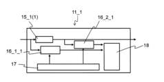
- the computer system 10 includes N arithmetic units 11_1 to 11_N (N is an integer equal to or greater than 1), an internal communication unit 13 that connects the arithmetic units 11_1 to 11_N, A host unit 12 that sets and manages operation parameters for the calculation units 11_1 to 11_N is provided.
- the calculation units 11_1 to 11_N are configured by processors, accelerators, etc., and include trace units 14_1 to 14_N.
- the tracing units 14_1 to 14_N are triggered by detection of a predetermined event at an arbitrary observation point of each computing unit 11_1 to 11_N, and change the operating frequency of each computing unit 11_1 to 11_N. Record the base event detection time.
- the trace units 14_1 to 14_N can record the event detection time for each data type or event type. Furthermore, arbitrary data may be recorded.
- the data processed by the calculation unit 11_1 is transferred to the calculation unit 11_2 via the internal communication unit 13. Subsequently, the data transfer is repeated, and the data is transferred to the calculation unit 11_N.
- a processing method for interlocking the calculation units 11_1 to 11_N there are a processing method in which a plurality of calculation units are connected in series, a processing method in which a plurality of calculation units are connected in parallel, a processing method in which both are combined, and the like.
- a desired service is provided and an application is processed by working together with a plurality of calculation units.
- the arithmetic units 11_1 to 11_N have a function of executing predetermined arithmetic processing on input data input from the outside of the computer system 10 .
- Arithmetic processing is, for example, processing to reduce/enlarge the image size when image data is input, processing to detect a specific object from the image data, processing to decrypt/encrypt the image data, etc. It is general arithmetic processing such as processing, aggregation, and combination.
- calculation units 11_1 to 11_N may be added or deleted regardless of whether the system is stopped or in operation.
- it can be realized by using an FPGA, which is a dynamically reconfigurable device, for only part of the computing unit.
- an accelerator card having a dedicated circuit specialized for specific calculations may be added.
- the host unit 12 has a function of setting and managing operation parameters for the calculation units 11_1 to 11_N, and more specifically has a function of controlling the calculation units 11_1 to 11_N and a function of storing data.
- the operation parameter is, for example, information for specifying an algorithm when switching between a plurality of algorithms in image processing, such as coefficients and threshold values in arithmetic processing.
- the host unit 12 sends circuit information for executing desired processing content to the operation unit. management of the entire computer system 10, such as setting
- the internal communication unit 13 connects the calculation units 11_1 to 11_N and has a communication function for exchanging data between the calculation units 11_1 to 11_N.
- commercial communication standards such as PCIe and Ethernet, and physical configurations that satisfy the communication standards, that is, PCIe switches and Ethernet switches, can be mentioned.
- a plurality of computing units providing computing functions are provided in the computing units 11_1 to 11_N
- a plurality of the observation points may be provided in the computing units 11_1 to 11_N.
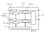
- the computing unit 11_1 in the computer system 10 includes a plurality (N units) of computing units 15_1(1) to 15_N(1) and a tracing unit 14_1.
- the number of computing units may be one.
- the trace unit 14_1 includes event generators 16_1_1 to 16_2_N, a time stamp unit 17, and a trace buffer .
- the event generators 16_1_1 to 16_2_N are connected to the input side and the output side of the calculators 15_1(1) to 15_N(1), respectively.
- the output of the time stamp section 17 is connected to event generators 16_1_1 to 16_2_N.
- the outputs of event generators 16_1_1-16_2_N are connected to trace buffer 18 .
- the event generators 16_1_1 to 16_2_N may be arranged on either the input side or the output side of the calculators 15_1(1) to 15_N(1), and may be arranged at any location. I wish I could. Also, a plurality of trace buffers 18 may be arranged, and at least one may be arranged.
- the event generators 16_1_1 to 16_2_N are inserted in arbitrary positions of the calculation units 11_1 to 11_N, and detect events (start and end of streams) for each type of data (user ID, session ID, stream ID, service ID). , generates a trigger for recording trace data including the detection time (hereinafter referred to as "time stamp value") in a trace buffer 18, which will be described later.
- the type of data is not limited to the above, and any information that can be used for organizing data, such as header information of packets used for organizing data and information possessed by signals running in parallel with data, can be applied. .
- the time stamp unit 17 has at least one clock counter, synchronizes the plurality of event generators 16_1_1 to 16_2_N (observation points), and acquires the time with the accuracy of the operating frequency of the calculation units 11_1 to 11_N.
- the operating frequency (clock frequency) of the arithmetic units 11_1 to 11_N is usually about several nanoseconds when the function is realized using an FPGA (field-programmable gate array).
- the trace buffer 18 records trace data triggered by event detection by the event generators 16_1_1 to 16_2_N.
- the trace data includes each detection time (time stamp value) obtained from the time stamp unit 17, an instance ID, an event type (event ID), a data type (TID), and arbitrary data.
- the trace data should have at least a timestamp value.
- the trace buffer 18 provides a constant amount of buffer, independent of the number of event generators.
- the timestamp value is a value unified within the computing unit (FPGA).
- the instance ID is an ID that distinguishes the event generator instance and indicates the location (observation point) where the event is detected.
- event ID is an ID that distinguishes event contents. For example, the distinction is made by passing the beginning of the stream or passing the end of the stream. Also, an event detection flag or the like is prepared at an arbitrary location of the data to detect that the flag has passed.
- Arbitrary data is data that is usually processed by a computer system, such as image data, numerical data, and text data.
- the data type is used, for example, to identify and classify the attributes of input data, and is information attached to the data itself, such as user ID, session ID, stream ID, and service ID. Also, the information for identifying the data type does not necessarily have to be added to the header of the packet, and may be uniquely defined in the payload of the packet, for example. Further, when a signal running parallel to data is used inside the arithmetic unit, the parallel running signal may be used to acquire the data type.
- Input data is composed of various elements and includes an event type (event ID), a data type (TID), and arbitrary data.
- the data processed by the calculator 15_1(1) of the calculator 11_1 is transmitted and input to the calculator 15_1(2) of the calculator 11_2.
- control signals (operations) of data to be input to the arithmetic units 11_1 to 11_N are observed.
- event generators 16_1_1 to 16_2_N detect an event
- the event generators 16_1_1 to 16_2_N acquire the event type, data type, and arbitrary data from the input data.
- event occurrence is, for example, when the head of the stream has passed or when the head of the stream has passed.
- the event generators 16_1_1 to 16_2_N add the instance ID and the time stamp value transmitted from the time stamp unit 17 to the acquired event type, data type, and arbitrary data.
- the trace data consists of a timestamp value, an instance ID, an event type, a data type, and arbitrary data.
- the trace data should include at least the timestamp value, and information in the computer system such as the processing time and data flow rate can be grasped based on the timestamp value. Also, the time when the problem occurred can be grasped.
- the trace data has an instance ID, so it is possible to grasp the location where the problem occurred.
- the trace data has an event type, so it is possible to grasp when the event occurred.
- the trace data has data types, so that the operating status for each data type can be grasped, and can be used for determination (described later) at the time of data deletion.
- trace data can be used when resuming processing (described later) by having arbitrary data.
- trace data can be used to manage trace data based on priority by having service priority information.
- event generators 16_1_1-16_2_N send the trace data to the trace buffer 18.
- the time stamp unit 17 receives (writes) the count start or stop setting transmitted from the host unit 12 .
- the clock counter is set to start or stop counting.
- Counting is started by the count start setting, and the counting is performed based on the operating frequencies of the respective calculation units 11_1 to 11_N. On the other hand, counting is stopped by the count stop setting.
- the event generators 16_1_1 to 16_2_N detect an event, they read the time counted by the clock counter as a timestamp value, and the timestamp value is sent to the event generators 16_1_1 to 16_2_N.
- event detection is determined by, for example, ON/OFF of a signal that indicates whether or not the data is valid among the signals that run in parallel with the data, or a field for event detection is set in a specific area of the data.
- the event is detected by preparing and using the bit string of the field.
- calculation units are synchronized as necessary.
- synchronization is achieved by inputting a signal for synchronization or a reset signal from the host unit to the operation units to be synchronized.
- the host unit 12 when reading trace data from the trace buffer 18, the host unit 12 sends a reset signal to the time stamp unit 17 to reset the value of the clock counter.
- the trace data received from the event generators 16_1_1 to 16_2_N are recorded and accumulated in the trace buffer 18.
- trace data transmitted from a plurality of event generators 16_1_1 to 16_2_N are recorded.
- writing and reading of trace data are executed by FIFO (First-In First-Out) common to all TIDs.
- FIFO First-In First-Out
- the host unit 12 reads the trace data from the trace buffer 18.
- the host unit 12 executes post-processing of the read (collected) data. Specifically, a search (GREP) is performed for each TID. Subsequently, they are visualized after being sorted by the time stamp section 17 .
- GREP search
- the event generator acquires the event type, data type, and arbitrary data from the input data when an event is detected.
- the computer system 10 can be operated by obtaining at least the time stamp value.
- calculation units 11_1 to 11_N can be added or deleted regardless of whether the computer system 10 is stopped or in operation.
- the computing units 15_1(1) to 15_N(1) can be eliminated.
- a plurality of event generators 16_1_1 to 16_2_N can be arranged at arbitrary locations in the trace units 14_1 to 14_N.
- the event generators 16_1_1 to 16_2_N may be arranged both before the input stage and after the output stage of the calculators 15_1(1) to 15_N(1). can be placed in
- the event generators 16_1_1 to 16_2_N before and after the calculators 15_1(1) to 15_N(1) may be deleted in the trace units 14_1 to 14_N.
- both event generators before the input stage and after the output stage of the arithmetic units 15_1(1) to 15_N(1) to be deleted may be deleted, and either the event generator before the input stage or the stage after the output stage may be deleted. You can remove event generators.
- a plurality of event generators can be added at any location, by newly adding only the event generator, it is possible to easily add a new arithmetic unit inside the arithmetic unit. Measurement of processing time and collection of trace data are possible.
- the circuit scale when adding a computing unit, the circuit scale can be reduced and power consumption can be suppressed compared to adding all of the event generator, time stamp unit, and trace buffer.
- the event generators placed before and after the computing unit may be deleted.
- trace data related to the event generator may be deleted.
- the trace data attached to the event detected by the event generator to be deleted does not necessarily have to be deleted.
- the trace data recorded by the trace units 14_1 to 14_N of the calculation units 11_1 to 11_N are used to efficiently resume processing when a failure occurs.
- the defect includes a packet loss that can normally occur, a stack of processing in the internal functional blocks of the arithmetic units 11_1 to 11_N, and the like.
- the trace unit 14_1 of the calculation unit 11_1 stores a time stamp value, an instance ID (information indicating a location where an event is detected), and arbitrary data as arbitrary trace data in the trace buffer 18. Record.
- the host unit 12 monitors the trace buffer 18 of the computer system at a predetermined cycle and measures the processing time in the arithmetic unit (step S11A).
- the host unit 12 sets the event generator 16_1_1 (first event generator) on the input side of the arithmetic unit 15_1(1) and the event generator 16_1_1 (first event generator) on the output side of the arithmetic unit 15_1(1).
- 16_2_1 second event generator
- 16_2_1 reads the first time stamp value and the second stamp value triggered by the detection of each predetermined event (first event, second event) from the trace buffer 18 ( get).
- the host unit 12 calculates the processing time from the difference between the first timestamp value and the second stamp value.
- the processing time of an arbitrary point is obtained by inputting each of the event generators arranged in an arbitrary point (interval, eg, before and after computing element 15_1(1)). It is obtained by the difference between the times (the first time stamp value and the second stamp value) at which the data passes.
- the measured processing time is compared with a predetermined threshold (step S12A). As a result, if the processing time is longer than a predetermined threshold, it is determined that a problem has occurred.
- step S13A the process detection point is grasped from the instance ID, and processing is restarted using arbitrary data recorded in any of the trace buffers 18 preceding the process detection point.
- the calculation units 11_1 to 11_N record trace data and monitor the trace buffer 18 at a predetermined cycle. , until the data is input to the arithmetic unit 15_1(2) of the next-stage arithmetic unit (for example, the arithmetic unit 11_2) (hereinafter referred to as “processing time between arithmetic units”) is measured (step S11B). .
- the event generator 16_2_1 in the preceding stage of the trace buffer 18 of the calculation unit 11_1 acquires a time stamp value (first stamp value), It is recorded in the trace buffer 18 of the calculation unit 11_1.
- a notification signal is transmitted from the trace buffer 18 of the computing unit 11_1 to the computing unit 15_1(2) of the computing unit 11_2 (dotted arrow in the figure), and this signal triggers the computing unit 15_1(1) of the computing unit 11_1. , is transferred to the calculator 15_1(2) of the calculator 11_2.
- the event generator 16_1_1 preceding the computing unit 15_1(2) of the computing unit 11_2 generates the timestamp value (second stamp value) is acquired and recorded in the trace buffer 18 of the calculation unit 11_2.
- the processing time between the calculation units is measured from the difference between the first stamp value and the second stamp value.
- the measured processing time is compared with a predetermined threshold (step S12B). As a result, if the measured time is longer than a predetermined threshold, it is determined that a problem has occurred.
- an event generator placed at an arbitrary position detects a predetermined event.
- An event generator placed at a position similarly acquires other time stamp values, calculates the difference between one time stamp value and another time stamp value, determines the occurrence of a failure, and performs processing. resume.
- the process can be operated normally without restarting from the beginning. Processing can be restarted by going back to the point where the error occurred.
- the host unit 12 manages the trigger for resuming the trace data processing. Alternatively, it may be managed by the calculation units 11_1 to 11_N.
- the trace data may have data type and event type. Also, trace data may be recorded for each data type or event type.
- ⁇ Second embodiment> A computer system control method according to a second embodiment of the present invention will be described with reference to FIG.
- the trace units 14_1 to 14_N of the calculation units 11_1 to 11_N are used to perform system quality control (state management/health check).
- the trace unit 14_1 of the calculation unit 11_1 includes a plurality of event generators 16_1_1 to 16_2_N.
- FIG. 5 shows a flowchart of the control method of the computer system 10 according to this embodiment.
- the computing unit 11_1 of the computer system 10 uses a plurality of event generators 16_1_1 to 16_2_N to collect times when data passes through each of the event generators 16_1_1 to 16_2_N (step S21).
- the computing unit 11_1 generates a timestamp value (for example, a first timestamp value and a second timestamp value).
- step S22 by obtaining the difference between the collected first time stamp value and second time stamp value, the time required to pass through the specific section in the calculation unit 11_1, that is, the processing time is calculated (step S22).
- step S23 the processing time is compared with a preset threshold.
- step S24 if the processing time is greater than the threshold, an abnormality detection of the computer system 10 is notified.
- time analysis processing it is not necessary to perform time analysis processing on all data. For example, the time (processing time) required to pass through a specific section in the calculation units 11_1 to 11_N is observed at predetermined measurement intervals, and if it falls within a predetermined range or if the processing time is longer than a predetermined threshold value. It is possible to monitor whether the computer system is operating normally by determining whether or not there is.
- test data may be input and the time required for this data to pass through the calculation units 11_1 to 11_N may be analyzed.
- the computing unit controls the computer system, but the host unit may also control the computer system.
- the trace data may have a data type along with the timestamp value. Furthermore, it may have an instance ID, an event type, and arbitrary data. Also, trace data may be recorded for each data type or event type.
- ⁇ Third embodiment> A method of controlling the computer system 10 according to the third embodiment of the present invention will be described with reference to FIG.
- flow management of the computer system 10 is executed using the trace units 14_1 to 14_N of the calculation units 11_1 to 11_N.
- the trace units 14_1 to 14_N of the calculation units 11_1 to 11_N record the time stamp value and the instance ID (information indicating the location where the event is detected) as trace data in the trace buffer 18, and the host unit 12 traces. Read data.
- FIG. 6 shows a flowchart of the control method of the computer system 10 according to this embodiment.
- the host unit 12 collects, as trace data from the trace buffer 18, for example, a time stamp value and an instance ID (information indicating the location where the event is detected) obtained by the event generator 16_1 at an arbitrary location for different events. (step S31).
- the event generator 16_1 collects the time stamp values of the beginning and end stored in the trace buffer 18, which are acquired when events of passing data, such as the beginning and end, are detected as triggers.
- the difference between the leading timestamp value and the trailing timestamp value is calculated as the data passage time.
- the amount of data (data flow rate) per unit time at a predetermined location is calculated by dividing the preset amount of input data (or output data) by the data transit time (step S32). ).
- step S33 the data flow rate is compared with a preset threshold.
- the data flow (route) is set to avoid data concentration. For example, when assigning a route, the route is set by avoiding a route exceeding a predetermined threshold grasped by the instance ID (information indicating the location where the event is detected) (step S34).
- the data flow (route) can be set so as to avoid data concentration.
- the computing unit may also control the computer system.
- the host unit 12 can grasp the operating status for each data type.
- instance IDs, event types, and arbitrary data may be recorded as trace data.
- trace data may be recorded for each data type or event type.
- input data is observed by the event generator 16_1_1 in the preceding stage of the calculator 15_1(1), and input data is observed by the event generator 16_2_1 in the subsequent stage.
- the time stamp value of the top of the input data is acquired by the event generator 16_1_1 as an event trigger.
- the time stamp value of the end of the input data is acquired by the event generator 16_1_1.
- the time stamp value of the head of the output data is acquired by the event generator 16_2_1.
- the event generator 16_2_1 acquires the time stamp value of the end of the output data.
- FIG. 7A shows timestamp values (Timestamp:Dec, Timestamp:0x), instance ID (Ins), event ID (Evt), decoded event ID (Dec), TID, and event data (EventData).
- H indicates the beginning of data and L indicates the end of data.
- the data volume of the input data and output data is 1MB. Further, the operating frequency of the arithmetic units 11_1 to 11_N is 250 MHz, 4 ns/cycle).
- the timestamp value (Timestamp: Dec) at the beginning of the input data is "406514", and the instance ID (Ins) is "10" (the upper part of the dotted square 41). Also, "HR-" of the event ID (Dec) indicates the passing of the head of the data as event occurrence.
- time stamp value (Timestamp: Dec) at the beginning of the output data is "401656", and the instance ID (Ins) is "11" (the lower part of the dotted square 41). Also, "HR-" of the event ID (Dec) indicates the passing of the head of the data as event occurrence.
- the timestamp value (Timestamp: Dec) at the end of the input data is "547791", and the instance ID (Ins) is “10" (the upper part of the dotted square 42). Also, “-LR-" of the event ID (Dec) indicates passage of the end of data as event occurrence.
- time stamp value (Timestamp: Dec) at the beginning of the output data is "547794”
- instance ID (Ins) is "11" (the lower part of the dotted square 42).
- “-LR-" of the event ID (Dec) indicates passage of the end of data as event occurrence.
- FIG. 7B schematically shows the relationship between the input data 43 and the output data 44.
- the input throughput that is, the data flow rate can be calculated from the difference (arrow 46) between the end time stamp value and the beginning time stamp value of the output data 44.
- the data flow rate is obtained by dividing the data amount by the difference between the beginning and end of the time stamp value of the data.
- the difference between the time stamp values at the start of output and the start of input that is, the time stamp value at the beginning of the output data 44 (401656 cycles) and the time stamp value at the beginning of the input data 43 (401564 cycles).
- the difference gives 92 cycles.
- the processing time for input data is obtained from the difference between the time stamp values at the start of output and the start of input.
- the time stamp values of input data and output data can be used to obtain the data processing time and data flow rate.
- processing can be restarted from the middle. As a result, there is no need to repeat the already executed process from the beginning. Moreover, the processing time can be shortened when the processing is not completed normally.
- the host unit 12 can centrally manage the state of each operation unit, for example, it is possible to set a flow of data that does not pass through an operation unit whose processing has stopped, and reduce the number of data for which processing is not normally completed.
- the trace units 14_1 to 14_N are provided independently of the calculation unit, the abnormal state of the calculation unit can be retained.
- the flow can be managed at the granularity of each user (per session).
- an event generator that detects events can be inserted in any part, it is possible to detect defects that occur only in specific flows.
- a computer system and its control method according to a second embodiment of the present invention will be described with reference to FIG.
- a computer system 10 according to the present embodiment has a configuration similar to that of the first embodiment.
- the trace buffer 18 overflows, making it difficult to record trace data. Therefore, it is necessary to erase the trace data.
- FIG. 8 shows a flowchart of the computer system control method according to this embodiment.
- At least the data type is recorded as trace data in the trace buffer 18 along with the time stamp value.
- instance IDs, event types, and arbitrary data may be recorded as trace data.
- trace data may be recorded for each data type or event type.
- the host unit 12 monitors the trace buffers 18 of the calculation units 11_1 to 11_N at predetermined intervals (step S51).
- step S52 it is determined whether or not a plurality of trace data for the same data type are recorded in the trace buffer 18 (step S52).
- step S53 the event detection time recorded in the trace buffer is erased based on the event detection time.
- the power consumption of the arithmetic unit can be reduced and power efficiency can be improved.
- trace data for each data type (user ID, session ID, stream ID, service ID)
- trace data for a specific data type (for example, the highest priority service) can be retained for a relatively long time. It is possible to provide a highly flexible computer system, such as increasing reliability by doing so.
- the present embodiment naturally has the same effect as the first embodiment.
- a computer system and its control method according to Modification 1 of the second embodiment of the present invention will be described.
- a computer system 10 according to this modification has a configuration similar to that of the first embodiment.
- At least the data type is recorded as trace data in the trace buffer 18 along with the time stamp value.
- instance IDs, event types, and arbitrary data may be recorded as trace data.
- trace data may be recorded for each data type or event type.
- the arithmetic units 11_1 to 11_N of the computer system 10 record (write) the trace data (latest trace data) received from the event generators 16_1_1 to 16_2_N in the trace buffer 18, determines whether or not trace data of the same data type as the latest trace data is recorded in the trace data already held by .
- a flag or the like may be added to prevent overwriting, and whether overwriting is possible or not may be determined based on the presence or absence of the flag.
- a computer system and its control method according to Modification 2 of the second embodiment of the present invention will be described.
- a computer system 10 according to this modification has a configuration similar to that of the first embodiment.
- At least a time stamp value is recorded in the trace buffer 18 as trace data.
- data type, instance ID, event type, and arbitrary data may be recorded as trace data.
- trace data may be recorded for each data type or event type.
- the data processed by the arithmetic unit 15_1(1) is transmitted from the arithmetic unit 15_1(1) of the arithmetic unit 11_1 in the preceding stage to the arithmetic unit 15_1(2) of the arithmetic unit 11_2 in the subsequent stage. .
- the post-stage calculation unit 11_2 sends a reception completion notification to the pre-stage calculation unit 11_1.
- the preceding stage computing section 11_1 receives the reception completion notification from the succeeding stage computing section 11_2, it erases the data in the trace buffer 18 of the preceding stage computing section 11_1.
- the computing unit 11_2 in the subsequent stage may send a reception completion notification to the host unit 12 and erase the data in the trace buffer 18 of the computing unit 11_1 in the preceding stage according to the instructions of the host unit 12 .
- the host unit 12 having a larger storage capacity than the trace buffer 18 collects and records data in the trace buffer 18, data collection or the completion of collection by the host unit 12 triggers , the data in the trace buffer 18 may be erased.
- the data in the trace buffer 18 may be erased when a preset time elapses.
- a computer system and its control method according to a third embodiment of the present invention will be described.
- a computer system 10 according to the present embodiment has a configuration similar to that of the first embodiment.
- FIG. 9 shows a flowchart of a computer system control method according to this embodiment.
- the host unit 12 sets a predetermined value as the initial value of the timestamp value (step S61).
- time stamp value when the calculation units 11_1 to 11_N start measuring the input data may be used as the initial value.
- the host unit 12 may write the start of counting to the time stamp unit 17, and the time stamp value at the start of counting may be used as the initial value.
- each computing unit 11_1 to 11_N obtains a time stamp value (step S62).
- the host unit 12 compares the acquired timestamp value with a predetermined reference value for the timestamp value (step S63).
- a predetermined reference value for the timestamp value is set in advance.
- the predetermined reference value indicates the allowable range of deviation of the time stamp value from a predetermined value, eg, the initial value.
- the host unit 12 resets the time stamp values of the computing units 11_1 to 11_N to a predetermined value, such as an initial value. (step S64).
- the time stamp value is unified. Since trace data can be handled, it can be easily analyzed after collection of trace data.
- the host unit 12 centrally sets the time stamp value to a predetermined value, for example, an initial value at the start of measurement or the like, it is possible to easily correct the deviation of the clock counters between the calculation units.
- the present embodiment naturally has the same effect as the first embodiment.
- a computer system and its control method according to Modification 1 of the third embodiment of the present invention will be described.
- a computer system 10 according to this modification has a configuration similar to that of the first embodiment.
- the host unit 12 adjusts the differences in the operating frequencies of the arithmetic units 11_1 to 11_N.
- the host unit 12 can generate the time stamp of the arithmetic unit 11_1.
- the time stamp values of the calculation units 11_1 and 11_2 are synchronized.
- the host unit 12 may synchronize the time stamp values of the computing units 11_1 and 11_2 by multiplying the time stamp value of the computing unit 11_2 by 1/2.
- a conversion reference value (eg, 100 MHZ) may be provided, and the counter values of all calculation units may be converted according to the reference value of 100 MHZ.
- the host unit controls the operating frequency of one arithmetic unit (for example, the arithmetic unit 11_1) to the operating frequency of another arithmetic unit (for example, the arithmetic unit 11_2).
- the time stamp value of the other computing unit eg, the computing unit 11_2
- a coefficient set in the other computing unit eg, the computing unit 11_2
- the operating frequencies of the other computing units eg, the computing unit 11_2
- a plurality of other calculation units may be provided. In this way, the difference between the counter values that differ for each calculation unit is adjusted.
- a computer system and its control method according to Modification 2 of the third embodiment of the present invention will be described.
- a computer system 10 according to this modification has a configuration similar to that of the first embodiment.
- a different conversion value (coefficient) is set in advance according to the frequency for each calculator. For example, if the frequency of the calculation unit 11_1 is 100 MHZ and the frequency of the calculation unit 11_2 is 200 MHZ, and the reference value is 100 MHZ, the conversion value (coefficient) of the calculation unit 11_1 is “1” and the conversion value of the calculation unit 11_2 is “1”. (coefficient) is "1/2".
- the same conversion may be performed when reading the clock counter value.
- the operating frequency of one arithmetic unit (for example, arithmetic unit 11_1) is changed to another arithmetic unit (for example, , arithmetic unit 11_2) are multiplied by a coefficient set in another arithmetic unit (for example, arithmetic unit 11_2) by the time stamp value of the other arithmetic unit (for example, arithmetic unit 11_2).
- a plurality of other calculation units may be provided. In this way, the difference between the counter values that differ for each calculation unit is adjusted.
- the computing unit in the computing unit may perform the processing, or measurement and determination may be performed separately in the computing unit. You may provide processing functions, such as.
- the present invention can be applied to computer systems in the information processing field.
Abstract
本発明のコンピュータシステムの制御方法は、複数の演算部(11_1~11_N)とホスト部(12)とを備え、複数の演算部がそれぞれトレースバッファ(18)を備え、入力データからの所定のイベントの検出を契機として、入力データの種別ごとに、演算部の動作周波数を基に取得されるイベントの検出時刻をトレースバッファに記録するコンピュータシステムの制御方法であって、ホスト部と演算部とのいずれかが、トレースバッファ内に記録された、イベントの検出時刻が属する入力データの種別を判定するステップと、判定の結果に応じて、同一の入力データの種別に属するイベントの検出時刻のうち、最新イベントの検出時刻を記録し、最新イベントの検出時刻以外のイベントの検出時刻を消去するステップとを備える。 これにより、本発明は、バッファのオーバーフローを抑制でき、物理的なバッファ量を削減するコンピュータシステムの制御方法を提供できる。
Description
本発明は、複数の演算部を有するコンピュータシステムおよびその制御方法に関する。
機械学習や人工知能(AI)やIoT(Internet of Things)など多くの分野で技術革新が進み、様々な情報やデータを活用することで、サービスの高度化・付加価値の提供が盛んに行われている。このような処理では、大量の計算をする必要があり、そのための情報処理基盤が必須である。
例えば、非特許文献1では、既存の情報処理基盤をアップデートする試みが展開されているが、急増するデータに対して現状のコンピュータが対応しきれていない。今後進展するためには、ムーアの法則を越える「ポストムーア技術」が確立されなければならないと指摘している。
ポストムーア技術として、例えば、非特許文献2では、フローセントリックコンピューティングという技術が開示されている。フローセントリックコンピューティングでは、データのある場所で処理を行うという従来のコンピューティングの考えではなく、計算機能が存在する場所にデータを移動して処理を行うという新たな概念が導入された。
上記のフローセントリックコンピューティングを実現するためには、データ移動に必要な広帯域な通信ネットワークが必要になるだけでなく、所望の演算性能が得るためには計算リソースを効率よく制御する必要がある。
フローセントリックコンピューティング(例えば、非特許文献2)では、複数の演算機能を連動させる手法が開示されている。
"NTT Technology Report for Smart World 2020,"日本電信電話株式会社, 2020年. https://www.rd.ntt/_assets/pdf/techreport/NTT_TRFSW_2020_EN_W.pdf.
R. Takano and T. Kudoh, "Flow-centric computing leveraged by photonic circuit switching for the post-moore era,"Tenth IEEE/ACM International Symposium on Networks-on-Chip (NOCS), Nara, 2016, pp. 1-3. https://ieeexplore.ieee.org/abstract/document/7579339.
しかしながら、複数の演算部が連動するコンピュータシステムにおいて、ホスト部を経由せずに演算部同士が主体的にデータを移動させるため、演算部内で生じた障害を特定することが困難であった。
また、入力データがある時刻に通過した演算部を特定するなどコンピュータシステムの内部状態を把握することが困難であった。
上述したような課題を解決するために、本発明に係るコンピュータシステムの制御方法は、複数の演算部とホスト部とを備え、前記複数の演算部がそれぞれトレースバッファを備え、入力データからの所定のイベントの検出を契機として、前記入力データの種別ごとに、前記演算部の動作周波数を基に取得される前記イベントの検出時刻を前記トレースバッファに記録するコンピュータシステムの制御方法であって、前記ホスト部と前記演算部とのいずれかが、前記トレースバッファ内に記録された、前記イベントの検出時刻が属する前記入力データの種別を判定するステップと、前記ホスト部と前記演算部とのいずれかが、判定の結果に応じて、同一の前記入力データの種別に属する前記イベントの検出時刻のうち、最新の前記イベントの検出時刻を記録し、前記最新の前記イベントの検出時刻以外の前記イベントの検出時刻を消去するステップとを備える。
また、本発明に係るコンピュータシステムの制御方法は、複数の演算部がそれぞれ演算器とトレースバッファを備え、入力データからの所定のイベントの検出を契機として、前記演算部の動作周波数を基に取得される前記イベントの検出時刻を前記トレースバッファに記録するコンピュータシステムの制御方法であって、前記複数の演算部のうち、一の演算部の演算器が、前記入力データを処理し、他の演算部の演算器に転送するステップと、前記他の演算部が、受信完了通知を発信するステップと、前記一の演算部が、前記受信完了通知を受信すると、前記一の演算部の前記トレースバッファに記録される前記イベントの検出時刻を消去するステップとを備える。
また、本発明に係るコンピュータシステムの制御方法は、複数の演算部とホスト部とを備え、複数の演算部がそれぞれトレースバッファを備え、入力データからの所定のイベントの検出を契機として、前記演算部の動作周波数を基に取得される前記イベントの検出時刻を前記トレースバッファに記録するコンピュータシステムの制御方法であって、前記ホスト部と前記演算部とのいずれかが、所定の時間の経過を契機として、前記トレースバッファに記録された前記イベントの検出時刻を消去することを特徴とする。
また、本発明に係るコンピュータシステムは、入力データを処理するコンピュータシステムであって、複数の演算部と、前記複数の演算部と接続し、前記複数の演算部を制御するホスト部を備え、前記複数の演算部の間で前記処理されたデータが転送され、前記演算部が、前記入力データからの所定のイベントの検出を契機として、トレースデータを記録するトレースバッファを備え、前記トレースデータが、前記演算部の動作周波数を基にする前記イベントの検出時刻であるタイムスタンプ値を有し、前記ホスト部と前記演算部とのいずれかが、所定の条件で、前記トレースバッファに記録される前記トレースデータを消去することを特徴とする。
本発明によれば、障害が生じた場合に、容易に、障害が生じた箇所を特定でき、障害発生時の内部でのデータ状況を把握できるコンピュータシステムおよびその制御方法を提供できる。
<第1の実施の形態>
本発明の第1の実施の形態に係るコンピュータシステムとその制御方法について、図1~図3を参照して説明する。
本発明の第1の実施の形態に係るコンピュータシステムとその制御方法について、図1~図3を参照して説明する。
<コンピュータシステムの構成>
本実施の形態に係るコンピュータシステム10は、図1に示すように、N個の演算部11_1~11_N(Nは1以上の整数)と、演算部11_1~11_Nを接続する内部通信部13と、演算部11_1~11_Nに対して動作パラメータを設定・管理するホスト部12とを備える。
本実施の形態に係るコンピュータシステム10は、図1に示すように、N個の演算部11_1~11_N(Nは1以上の整数)と、演算部11_1~11_Nを接続する内部通信部13と、演算部11_1~11_Nに対して動作パラメータを設定・管理するホスト部12とを備える。
演算部11_1~11_Nは、プロセッサやアクセラレータなどにより構成され、トレース部14_1~14_Nを備える。
トレース部14_1~14_Nは、演算部11_1~11_Nが連動する際に、各演算部11_1~11_Nの任意の観測ポイントにおいて、所定のイベントの検出を契機として、各演算部11_1~11_Nの動作周波数を基にしたイベント検出時刻を記録する。
ここで、トレース部14_1~14_Nは、データ種別またはイベント種別ごとに、イベント検出時刻を記録できる。さらに、任意のデータを記録してもよい。
演算部11_1~11_Nの連動において、演算部11_1で処理されたデータが、内部通信部13を介して、演算部11_2に転送される。引き続き、データの転送が繰り返され、データが演算部11_Nに転送される。
なお、演算部11_1~11_Nの連動の方法として、複数の演算部を直列に接続する処理方法や、複数の演算部を並列に接続する処理方法や、両者を組み合せた処理方法などが挙げられる。複数の演算部が連動することで、所望のサービスを提供し、アプリケーションを処理する。
演算部11_1~11_N(Nは1以上の整数)は、コンピュータシステム10の外部から入力される入力データに対して所定の演算処理を実行する機能を有する。演算処理とは、例えば、画像データが入力された際に画像サイズを縮小・拡大する処理や、画像データから特定の物体を検出する処理、画像データを復号・暗号化する処理など、入力データに対する加工、集計、結合などの一般的な演算処理である。
また、演算部11_1~11_Nは、当該システムの停止中・稼働中を問わず、追加・削除してもよい。例えば、演算器の一部分のみを動的再構成が可能なデバイスであるFPGAを用いることで実現することができる。また、演算部11_1~11_Nの実装方法として、特定の演算に特化した専用回路を具備するアクセラレータカードを追加しても良い。また、演算部の中に演算機能を提供する演算器を複数具備することもできる。
ホスト部12は、演算部11_1~11_Nに対して動作パラメータを設定・管理する機能を有し、詳細には演算部11_1~11_Nを制御する機能や、データを記憶する機能を有する。動作パラメータは、例えば、画像処理において複数のアルゴリズムを切り替えて使う場合、アルゴリズムを特定するための情報であり、演算処理における係数や閾値などである。
また、当該システムの稼働開始後であっても演算部の追加・削除ができる場合、ホスト部12は、その演算部に対して、所望の処理内容を実行するための回路情報を演算部に対して設定するなど、コンピュータシステム10全体の管理を行う。
内部通信部13は、演算部11_1~11_Nを接続するとともに、演算部11_1~11_N間でデータの授受を行うための通信機能を有する。具体的には、PCIeやイーサネットなど市中の通信規格と前記通信規格を満足する物理構成、すなわちPCIeスイッチやイーサネットスイッチが挙げられる。
また、演算部11_1~11_Nの中に演算機能を提供する演算器を複数具備する場合、前記観測ポイントを演算部11_1~11_Nの中に複数設けてもよい。
<演算部の構成>
コンピュータシステム10における演算部11_1は、図2に示すように、複数(N台)の演算器15_1(1)~15_N(1)と、トレース部14_1とを備える。ここで、演算器は1台であってもよい。
コンピュータシステム10における演算部11_1は、図2に示すように、複数(N台)の演算器15_1(1)~15_N(1)と、トレース部14_1とを備える。ここで、演算器は1台であってもよい。
トレース部14_1は、イベントジェネレータ16_1_1~16_2_Nと、タイムスタンプ部17と、トレースバッファ18とを備える。
イベントジェネレータ16_1_1~16_2_Nは、演算器15_1(1)~15_N(1)の入力側と出力側それぞれに接続される。タイムスタンプ部17の出力が、イベントジェネレータ16_1_1~16_2_Nに接続される。イベントジェネレータ16_1_1~16_2_Nの出力は、トレースバッファ18に接続される。
ここで、イベントジェネレータ16_1_1~16_2_Nは、演算器15_1(1)~15_N(1)の入力側と出力側いずれかに配置されればよく、任意の箇所に配置されればよく、少なくとも1台配置されればよい。また、トレースバッファ18は複数台配置されてもよく、少なくとも1台配置されればよい。
イベントジェネレータ16_1_1~16_2_Nは、演算部11_1~11_Nの任意の箇所に挿入されて、データの種別(ユーザID、セッションID、ストリームID、サービスID)ごとにイベント(ストリームの先頭、末尾)を検出し、検出時刻(以下、「タイムスタンプ値」という。)を含むトレースデータを後述するトレースバッファ18に記録する契機を発生させる。
また、データの種別は上記に限らず、データを整理するために用いるパケットのヘッダ情報や、データと並走する信号が有する情報など、データの整理に利用できる情報であれば適用することができる。
タイムスタンプ部17は、少なくとも1台のクロックカウンタを備え、複数のイベントジェネレータ16_1_1~16_2_N(観測ポイント)間を同期させるとともに、演算部11_1~11_Nの動作周波数の精度で時刻を取得する。ここで、演算部11_1~11_Nの動作周波数(クロック周波数)は、FPGA(field-programmable gate array)を用いて当該機能を実現する場合、通常、数ナノ秒程度である。
トレースバッファ18は、イベントジェネレータ16_1_1~16_2_Nによるイベント検出を契機として、トレースデータを記録する。ここで、トレースデータは、タイムスタンプ部17から取得した各検出時刻(タイムスタンプ値)と、インスタンスIDと、イベント種別(イベントID)と、データ種別(TID)と、任意のデータとを有する。
ここで、トレースデータは、少なくともタイムスタンプ値を有すればよい。
ここで、トレースデータは、少なくともタイムスタンプ値を有すればよい。
また、トレースバッファ18は、イベントジェネレータの数に依存することなく、一定のバッファ量を提供する。
ここで、タイムスタンプ値は、演算部(FPGA)内で統一された値である。
また、インスタンスIDは、イベントジェネレータ・インスタンスを区別し、前記イベントを検出する箇所(観測ポイント)を示すIDである。
また、イベント種別(イベントID)は、イベント内容を区別するIDである。例えば、ストリームの先頭の通過またはストリームの終端の通過により区別する。また、データの任意の箇所にイベント検出用のフラグ等を用意して、当該フラグが通過したことを検出する。
また、任意のデータは、画像データ、数値データ、文章データなど通常コンピュータシステムで処理されるデータである。
また、データ種別は、例えば、入力データの属性などを識別・分類したりするために用いられ、ユーザID、セッションID、ストリームID、サービスIDなど、データ本体に付属する情報である。また、データ種別を識別するための情報は必ずしもパケットのヘッダに付与されなくともよく、例えば、パケットのペイロードに独自に定義してもよい。また、演算部の内部において、データと並走する信号を用いる場合、データ種別を取得するのに並走信号を用いてもよい。
<コンピュータシステムの動作>
本実施の形態に係るコンピュータシステム10の動作を、以下に説明する。
本実施の形態に係るコンピュータシステム10の動作を、以下に説明する。
コンピュータシステム10の演算部11_1において、演算器15_1(1)~15_N(1)にデータが入力される。入力されるデータは、様々な要素から構成され、イベント種別(イベントID)と、データ種別(TID)と、任意のデータを含む。
ここで、演算部11_1の演算器15_1(1)で処理されたデータは送信され、演算部11_2の演算器15_1(2)に入力する。
イベントジェネレータ16_1_1~16_2_Nにおいて、まず、演算部11_1~11_Nに入力するデータの制御信号(動作)を観測する。
イベントジェネレータ16_1_1~16_2_Nがイベントを検出すると、イベントジェネレータ16_1_1~16_2_Nが、入力データから、イベント種別と、データ種別と、任意のデータを取得する。ここで、イベント発生は、例えば、ストリームの先頭が通過した時、またはストリームの先頭が通過した時である。
イベントジェネレータ16_1_1~16_2_Nで、取得されたイベント種別とデータ種別と任意のデータに、インスタンスIDと、タイムスタンプ部17から送信されたタイムスタンプ値とが加えられる。その結果、トレースデータは、タイムスタンプ値と、インスタンスIDと、イベント種別と、データ種別と、任意のデータとで構成される。
ここで、トレースデータは、少なくともタイムスタンプ値を含めばよく、タイムスタンプ値を基に処理時間、データ流量などのコンピュータシステム内の情報を把握できる。また、不具合が生じた時刻なども把握できる。
さらに、トレースデータは、インスタンスIDを有することにより、不具合が生じた箇所を把握できる。
また、トレースデータは、イベント種別を有することにより、イベント発生時を把握できる。
また、トレースデータは、データ種別を有することにより、データ種別ごとの稼働状況を把握でき、データ消去時の判定(後述)に用いることができる。
また、トレースデータは、任意のデータを有することにより、処理の再開(後述)時に用いることができる。
また、トレースデータは、サービスの優先度情報を有することにより、優先度に基づくトレースデータの管理に用いることができる。
最後に、イベントジェネレータ16_1_1~16_2_Nが、トレースデータをトレースバッファ18に送信する。
また、タイムスタンプ部17において、ホスト部12から送信されたカウントの開始又は停止設定が受信(書き込み)される。
これを契機に、クロックカウンタにカウントの開始又は停止が設定される。
カウントの開始設定によりカウントは開始され、カウントは各演算部11_1~11_Nの動作周波数を基にして実行される。一方、カウントの停止設定によりカウントは停止される。
イベントジェネレータ16_1_1~16_2_Nはイベントを検出すると、クロックカウンタがカウントする時刻を、タイムスタンプ値として読み出し、タイムスタンプ値がイベントジェネレータ16_1_1~16_2_Nに送信される。
また、イベントの検出は例えば、データと並走する信号のうち、有効なデータであるか否かを示す信号のON/OFF用いて判定したり、データの特定の領域にイベント検出用のフィールドを用意して、当該フィールドのビット列を用いたりすることで、イベントを検出する。
ここで、必要に応じて、演算部(FPGA)間で同期させる。なお、演算部間で同期させる方法として、ホスト部から同期をする演算部に対して同期させるための信号や、リセット信号、を入力することで、同期を図る。
また、ホスト部12は、トレースバッファ18からトレースデータを読み出す時に、タイムスタンプ部17にリセット信号を送信し、クロックカウンタの値をリセットする。
トレースバッファ18において、イベントジェネレータ16_1_1~16_2_Nより受信されたトレースデータが、トレースバッファ18に記録され蓄積される。
ここで、複数のイベントジェネレータ16_1_1~16_2_Nから送信されたトレースデータが記録される。また、トレースデータの書き込み、読み出しは全TIDで共通のFIFO(First-In First-Out)で実行される。
次に、ホスト部12が、トレースデータを、トレースバッファ18から読み出す。
最後に、ホスト部12で、読み出した(回収)データの後処理を実行する。詳細には、TIDごとに検索(GREP)する。引き続き、タイムスタンプ部17でソートした後に可視化する。
ここでは、イベントジェネレータが、イベント検出時に入力データから、イベント種別と、データ種別と、任意のデータを取得する例を示したが、イベント種別と、データ種別と、任意のデータを取得しなくとも、上述の通り、少なくともタイムスタンプ値を取得すればコンピュータシステム10を動作できる。
<演算部および演算器の追加・削除>
コンピュータシステム10において、演算部11_1~11_Nを、コンピュータシステム10の停止中・稼働中を問わず、追加または削除できる。
コンピュータシステム10において、演算部11_1~11_Nを、コンピュータシステム10の停止中・稼働中を問わず、追加または削除できる。
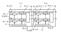
また、例えば、図3Aに示す演算部11_1において、図3Bに示すように、イベントジェネレータ16_1_2~16_2_Nを新たに配置(追加)してタイムスタンプ部17とトレースバッファ18と接続することにより、演算器15_1(1)~15_N(1)を追加できる。
また、演算部11_1において、イベントジェネレータ16_1_2~16_2_Nを削除することにより、演算器15_1(1)~15_N(1)を削除できる。
演算器15_1(1)~15_N(1)を追加するとき、トレース部14_1~14_Nにおいて、複数のイベントジェネレータ16_1_1~16_2_Nを任意の箇所に配置することができる。
ここで、イベントジェネレータ16_1_1~16_2_Nを演算器15_1(1)~15_N(1)の入力の前段と出力の後段との両方に配置してもよく、入力の前段と出力の後段とのいずれか一方に配置してもよい。
演算器15_1(1)~15_N(1)を削除するとき、トレース部14_1~14_Nにおいて、演算器15_1(1)~15_N(1)の前後のイベントジェネレータ16_1_1~16_2_Nを削除すればよい。
ここで、削除する演算器15_1(1)~15_N(1)の入力の前段と出力の後段との両方のイベントジェネレータを削除してもよく、入力の前段と出力の後段とのいずれか一方のイベントジェネレータを削除してもよい。
本実施の形態によれば、複数のイベントジェネレータを任意の箇所に追加できるため、イベントジェネレータのみを新たに追加することにより、容易に演算部の内部に新たに演算器を追加でき、演算器における処理時間の計測、トレースデータの収集が可能となる。
また、複数のイベントジェネレータを任意の箇所から削除できるため、イベントジェネレータのみを削除すれば、容易に演算部の内部で演算器を削除できる。
また、演算器を追加する場合にイベントジェネレータとタイムスタンプ部とトレースバッファとを全て追加する場合に比べて、回路規模を縮小でき、消費電力を抑制できる。
また、演算部から演算器を削除する場合、演算器の前後に配置されているイベントジェネレータを削除してもよい。このとき、イベントジェネレータに関するトレースデータを削除してもよい。また、削除されるイベントジェネレータで検出したイベントに付随するトレースデータは、必ずしも削除しなくともよい。
<第1の実施例>
本発明の第1の実施例に係るコンピュータシステム10の制御方法について、図4A、Bを参照して説明する。
本発明の第1の実施例に係るコンピュータシステム10の制御方法について、図4A、Bを参照して説明する。
本実施例では、コンピュータシステム10において、演算部11_1~11_Nのトレース部14_1~14_Nが記録するトレースデータを用いて、不具合時に効率的に処理を再開する。ここで、不具合とは、通常発生し得るパケットロスや、演算部11_1~11_Nの内部の機能ブロックにおける処理のスタックなどである。
コンピュータシステム10において、例えば、演算部11_1のトレース部14_1は、トレースバッファ18で任意のトレースデータとして、タイムスタンプ値と、インスタンスID(イベントを検出する箇所を示す情報)と、任意のデータとを記録する。
本実施例に係るコンピュータシステム10の制御方法の一例として、ホスト部12が制御(管理)する場合を、図4Aを参照して説明する。
初めに、ホスト部12が所定の周期でコンピュータシステムのトレースバッファ18をモニタして、演算部内の処理時間を計測する(ステップS11A)。
ここで、処理時間の計測において、まず、ホスト部12が、演算器15_1(1)の入力側のイベントジェネレータ16_1_1(第1のイベントジェネレータ)と、演算器15_1(1)の出力側のイベントジェネレータ16_2_1(第2のイベントジェネレータ)それぞれの所定のイベント(第1のイベント、第2のイベント)の検出を契機とする第1のタイムスタンプ値と第2のスタンプ値を、トレースバッファ18から読み出す(取得する)。
引き続き、ホスト部12が、第1のタイムスタンプ値と第2のスタンプ値との差分より、処理時間を算出する。
このように、任意の箇所(区間、例えば、演算器15_1(1))の処理時間は、任意の箇所(区間、例えば、演算器15_1(1)の前後)に配置されたイベントジェネレータそれぞれを入力データが通過する時刻(第1のタイムスタンプ値と第2のスタンプ値)の差分により取得される。
次に、計測された処理時間を、予め設定された所定の閾値と比較する(ステップS12A)。その結果、処理時間が所定の閾値より長い場合に、不具合が発生したと判定する。
最後に、不具合が発生した場合には、インスタンスIDより処理検出箇所を把握して、この処理検出箇所よりも前段のいずれかのトレースバッファ18に記録される任意のデータを用いて、処理を再開する(ステップS13A)。
また、本実施例に係るコンピュータシステム10の制御方法の一例として、演算部11_1~11_Nが制御(管理)する場合を、図4B、Cを参照して説明する。
初めに、演算部11_1~11_Nは、トレースデータを記録するとともに、所定の周期でトレースバッファ18を監視し、任意の演算部(例えば演算部11_1)のトレースバッファ18にタイムスタンプ値が記録されてから、次段の演算部(例えば演算部11_2)の演算器15_1(2)にデータが入力されるまでの時間(以下、「演算部間の処理時間」という。)を計測する(ステップS11B)。
この演算部間の処理時間の計測では、例えば、図4Cに示すように、まず、演算部11_1のトレースバッファ18の前段のイベントジェネレータ16_2_1がタイムスタンプ値(第1のスタンプ値)を取得し、演算部11_1のトレースバッファ18で記録される。
引き続き、演算部11_1のトレースバッファ18から演算部11_2の演算器15_1(2)に通知信号が送信され(図中、点線矢印)、この信号を契機に、演算部11_1の演算器15_1(1)から演算部11_2の演算器15_1(2)にデータが転送される。
引き続き、演算部11_2の演算器15_1(2)に入力されるデータのイベントの検出を契機に、演算部11_2の演算器15_1(2)の前段のイベントジェネレータ16_1_1が、タイムスタンプ値(第2のスタンプ値)を取得し、演算部11_2のトレースバッファ18で記録される。
これらの第1のスタンプ値と第2のスタンプ値の差分より、演算部間の処理時間が計測される。
次に、計測された処理時間を、予め設定された所定の閾値と比較する(ステップS12B)。その結果、計測された時間が所定の閾値より長い場合に、不具合が発生したと判定する。
最後に、不具合が発生した場合には、トレースバッファ18に記録されるインスタンスIDにより把握される処理検出箇所よりも前段のいずれかのトレースバッファ18に記録される任意のデータを用いて、処理を再開する(ステップS13B)。
ここで、トレースバッファに記録したタイムスタンプ値を用いて処理時間を計測する例を示したが、イベントジェネレータが取得したタイムスタンプ値を直接用いて処理時間を計測してもよい。
このように、本実施例に係るコンピュータシステムの制御方法では、任意の位置に配置されるイベントジェネレータが、所定のイベントを検出し、これを契機として、一のタイムスタンプ値を取得し、他の位置に配置されるイベントジェネレータが、同様に他のタイムスタンプ値を取得し、一のタイムスタンプ値と、他のタイムスタンプ値との差分を算出することにより、不具合の発生を判定し、処理を再開する。
本実施例に係るコンピュータシステムの制御方法によれば、トレース部14_1~14_Nが記録するトレースデータを用いることにより、不具合が発生した場合に、処理を最初から再開せずに、正常に動作していた箇所まで遡り処理を再開できる。
また、トレースデータの処理を再開させる契機は、ホスト部12が管理する。または、演算部11_1~11_Nが管理してもよい。
また、処理の再開は、必ずしも特定の機能ブロックに限定しなくともよく、例えば、演算部の入力まで遡って処理を再開してもよい。
本実施例では、インスタンスIDにより処理検出箇所を把握する例を示したが、これに限らず、予め設定される演算器の処理速度と、計測されるタイムスタンプ値とを用いて処理検出箇所を導出してもよい。
本実施例では、不具合の発生を把握するために、処理時間を用いる例を示したが、これに限らず、データ流量(後述)などを用いてもよい。
本実施例では、トレースデータは、データ種別、イベント種別を有してもよい。また、トレースデータが、データ種別またはイベント種別ごとに記録されてもよい。
<第2の実施例>
本発明の第2の実施例に係るコンピュータシステムの制御方法について、図5を参照して説明する。本実施例では、コンピュータシステムにおいて、演算部11_1~11_Nのトレース部14_1~14_Nを用いて、システムの品質管理(ステート管理/ヘルスチェック)を実行する。
本発明の第2の実施例に係るコンピュータシステムの制御方法について、図5を参照して説明する。本実施例では、コンピュータシステムにおいて、演算部11_1~11_Nのトレース部14_1~14_Nを用いて、システムの品質管理(ステート管理/ヘルスチェック)を実行する。
コンピュータシステム10において、例えば、演算部11_1のトレース部14_1は、複数のイベントジェネレータ16_1_1~16_2_Nを備える。
図5に、本実施例に係るコンピュータシステム10の制御方法のフローチャート図を示す。
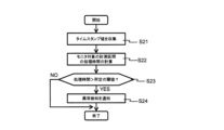
初めに、例えば、コンピュータシステム10の演算部11_1は、複数のイベントジェネレータ16_1_1~16_2_Nを用いて、データが各イベントジェネレータ16_1_1~16_2_Nを通過する時刻を収集する(ステップS21)。
詳細には、演算部11_1が、異なる箇所に配置されるイベントジェネレータ(例えば、イベントジェネレータ16_1_1とイベントジェネレータ16_2_1)それぞれでの所定のイベントの検出に基づき、タイムスタンプ値(例えば、第1のタイムスタンプ値と第2のタイムスタンプ値)を収集する。
次に、収集された第1のタイムスタンプ値と第2のタイムスタンプ値との差分を求めることにより、演算部11_1内の特定区間の通過に要する時間すなわち処理時間を計算する(ステップS22)。
次に、処理時間を、予め設定された所定の閾値と比較する(ステップS23)。
比較の結果、処理時間が閾値より大きい場合に、コンピュータシステム10の異常検知を通知する(ステップS24)。
このように、本実施例に係るコンピュータシステムの管理方法によれば、コンピュータシステムが正常に稼働しているか否かをモニタできる。
また、必ずしもすべてのデータに対して時間の解析処理を実行しなくともよい。例えば、予め指定した計測間隔で演算部11_1~11_N内の特定区間の通過に要した時間(処理時間)を観測し、所定の範囲内に収まるか、もしくは所定の閾値よりも処理時間が伸びているか否かを判定することにより、コンピュータシステムが正常に稼働しているか否かをモニタできる。
また、テスト用のデータを入力して、このデータが演算部11_1~11_Nの内部を通過するのに要する時間を解析してもよい。
本実施例では、イベントジェネレータが取得したタイムスタンプ値を直接用いて処理時間を計測する例を示したが、トレースバッファにタイムスタンプ値を記録した後に、トレースバッファに記録したタイムスタンプ値を用いて処理時間を計測してもよい。
本実施例では、処理時間を用いてコンピュータシステムの状況を把握する例を示したが、これに限らず、データ流量などを用いてもよい。
本実施例では、演算部がコンピュータシステムを制御する例を示したが、ホスト部がコンピュータシステムを制御してもよい。
本実施例では、トレースデータは、タイムスタンプ値とともに、データ種別を有してもよい。さらに、インスタンスID、イベント種別、任意のデータを有してもよい。また、トレースデータが、データ種別またはイベント種別ごとに記録されてもよい。
<第3の実施例>
本発明の第3の実施例に係るコンピュータシステム10の制御方法について、図6を参照して説明する。本実施例では、コンピュータシステム10において、演算部11_1~11_Nのトレース部14_1~14_Nを用いて、コンピュータシステム10のフロー管理を実行する。
本発明の第3の実施例に係るコンピュータシステム10の制御方法について、図6を参照して説明する。本実施例では、コンピュータシステム10において、演算部11_1~11_Nのトレース部14_1~14_Nを用いて、コンピュータシステム10のフロー管理を実行する。
コンピュータシステム10において、演算部11_1~11_Nのトレース部14_1~14_Nがトレースデータとして、タイムスタンプ値とインスタンスID(イベントを検出する箇所を示す情報)をトレースバッファ18に記録し、ホスト部12がトレースデータを読み出す。
図6に、本実施例に係るコンピュータシステム10の制御方法のフローチャート図を示す。
初めに、ホスト部12が、トレースバッファ18よりトレースデータとして、例えば、任意の箇所でイベントジェネレータ16_1が異なるイベントで取得したタイムスタンプ値とインスタンスID(イベントを検出する箇所を示す情報)とを収集する(ステップS31)。
詳細には、イベントジェネレータ16_1において、通過するデータのイベント、例えば先頭および終端それぞれの検出を契機として取得され、トレースバッファ18に記憶された先頭および終端のタイムスタンプ値を収集する。
次に、先頭のタイムスタンプ値と終端のタイムスタンプ値との差分をデータの通過時間として算出する。
次に、予め設定されている入力データ(または出力データ)のデータ量を、データの通過時間で除することにより、所定の箇所における単位時間当たりのデータ量(データ流量)を計算する(ステップS32)。
次に、データ流量を、予め設定された所定の閾値と比較する(ステップS33)。
比較の結果、データ流量が閾値より大きい場合に、データの集中を回避するようにデータフロー(経路)を設定する。例えば、経路を割り当てる際に、インスタンスID(イベントを検出する箇所を示す情報)により把握される所定の閾値を超えた経路を回避して、経路を設定する(ステップS34)。
このように、本実施例に係るコンピュータシステムの管理方法によれば、データの集中を回避するようにデータフロー(経路)を設定できる。
本実施例で、トレースバッファに記録したタイムスタンプ値を用いて処理時間を計測する例を示したが、イベントジェネレータが取得したタイムスタンプ値を直接用いて処理時間を計測してもよい。
また、ホスト部がコンピュータシステムを制御する例を示したが、演算部がコンピュータシステムを制御してもよい。
また、トレースデータが、データ種別に関する情報を有すれば、ホスト部12は、データ種別ごとの稼働状況を把握できる。
これにより、コンピュータシステム10では、特定のフローにのみデータが集中している場合に、当該フローから他の負荷の低いフローにデータを移行させることにより、データの集中を回避でき、フロー管理を実行できる。
また、トレースデータは、インスタンスID、イベント種別、任意のデータが記録されてもよい。また、トレースデータが、データ種別またはイベント種別ごとに記録されてもよい。
また、特定のフローや特定の箇所に発生した障害を検出すれば、障害が発生した際に、当該フローを迂回する経路を設定するようにフローを管理できる。
また、データの経路が異なる複数のフローを有する演算部において不具合が発生した場合に、当該フロー以外のフローを他の演算部に回避させた後に、当該演算部の交換、リセット、解析などを実施できる。
<演算部の計測例>
本実施例に係るコンピュータシステム10の制御方法において、演算部における処理時間とデータ流量との計測の一例を、図7A、Bを参照して説明する。
本実施例に係るコンピュータシステム10の制御方法において、演算部における処理時間とデータ流量との計測の一例を、図7A、Bを参照して説明する。
本計測例では、例えば、演算器15_1(1)の前段のイベントジェネレータ16_1_1で入力データが観測され、後段のイベントジェネレータ16_2_1で入力データが観測される。
入力データの先頭がイベントジェネレータ16_1_1を通過する時をイベントの契機として、イベントジェネレータ16_1_1に入力データの先頭のタイムスタンプ値が取得される。
同様に、入力データの終端がイベントジェネレータ16_1_1を通過する時をイベントの契機として、イベントジェネレータ16_1_1に入力データの終端のタイムスタンプ値が取得される。
一方、出力データの先頭がイベントジェネレータ16_2_1を通過する時をイベントの契機として、イベントジェネレータ16_2_1に出力データの先頭のタイムスタンプ値が取得される。
同様に、出力データの終端がイベントジェネレータ16_2_1を通過する時をイベントの契機として、イベントジェネレータ16_2_1に出力データの終端のタイムスタンプ値が取得される。
図7Aに、トレースデータの一例を示す。図7Aにおいて、タイムスタンプ値(Timestamp:Dec、Timestamp:0x)、インスタンスID(Ins)、イベントID(Evt)、デコード化されたイベントID(Dec)、TID、イベントデータ(EventData)を示す。
デコード化されたイベントID(Dec)において、Hはデータの先頭、Lはデータの終端を示す。
入力データと出力データのデータ量は1MBである。また、演算部11_1~11_Nの動作周波数は250MHz、4ns/サイクル)である。
入力データの先頭のタイムスタンプ値(Timestamp:Dec)は、「406514」であり、インスタンスID(Ins)が「10」である(点線四角41内上段)。また、イベントID(Dec)の「H-R-」がイベント発生としてデータ先頭の通過を示す。
同様に、出力データの先頭のタイムスタンプ値(Timestamp:Dec)は、「401656」であり、インスタンスID(Ins)が「11」である(点線四角41内下段)。また、イベントID(Dec)の「H-R-」がイベント発生としてデータ先頭の通過を示す。
また、入力データの終端のタイムスタンプ値(Timestamp:Dec)は、「547791」であり、インスタンスID(Ins)が「10」である(点線四角42内上段)。また、イベントID(Dec)の「-LR-」がイベント発生としてデータ終端の通過を示す。
同様に、出力データの先頭のタイムスタンプ値(Timestamp:Dec)は、「547794」であり、インスタンスID(Ins)が「11」である(点線四角42内下段)。また、イベントID(Dec)の「-LR-」がイベント発生としてデータ終端の通過を示す。
図7Bに、入力データ43と出力データ44との関係を模式的に示す。入力データ43がイベントジェネレータ16_1_1を通過する時間は、終端のタイムスタンプ値(547791サイクル)と先頭のタイムスタンプ値(401564サイクル)との差分(矢印45)より、146227サイクル=584.9μsecと算出される。したがって、入力スループットすなわちデータ流量として、1MB/584.9μsec=約1.8GB/secが得られる。
同様に、出力データ44の終端のタイムスタンプ値と先頭のタイムスタンプ値との差分(矢印46)より、入力スループットすなわちデータ流量を算出できる。
このように、演算部において、データ流量は、データ量を、データのタイムスタンプ値の先頭と終端との差分で除することにより得られる。
また、処理時間(レイテンシ)として、出力開始と入力開始のタイムスタンプ値の差分すなわち出力データ44の先頭のタイムスタンプ値(401656サイクル)と入力データ43の先頭のタイムスタンプ値(401564サイクル)との差分より、92サイクルが得られる。
このように、演算部において、入力データの処理時間は、出力開始と入力開始のタイムスタンプ値の差分より得られる。
以上のように、本発明に係るコンピュータシステムの制御方法において、入力データと出力データのタイムスタンプ値を用いて、データの処理時間とデータ流量とを取得できる。
<効果>
本発明の実施の形態および実施例に係るコンピュータシステムおよびその管理方法によれば、コンピュータシステムにおける演算処理が、途中で停止する場合または正常に処理が完了しない場合に、複数の演算部のうち、処理が停止した演算部を容易に検出、特定できる。
本発明の実施の形態および実施例に係るコンピュータシステムおよびその管理方法によれば、コンピュータシステムにおける演算処理が、途中で停止する場合または正常に処理が完了しない場合に、複数の演算部のうち、処理が停止した演算部を容易に検出、特定できる。
また、トレースバッファ18がデータを記録しているため、処理の途中から再開することができる。その結果、すでに実行した処理を再度、最初から繰り返す必要がなくなる。また、正常に処理が完了しない場合に、処理時間を短縮できる。
また、ホスト部12で各演算部の状態を一元管理できるため、例えば、処理が停止した演算部を経由しないデータのフローを設定でき、正常に処理が完了しないデータの数を削減できる。
また、データ種別(ユーザID、セッションID、ストリームID、サービスID)ごとにイベントを検出できトレースデータを蓄積できるため、容易に、特定のデータ種別に着目して品質管理や不具合解析等を実行できる。
また、演算部と独立してトレース部14_1~14_Nを備えるため、演算部の異常状態を保持できる。
また、ユーザ毎(セッション毎)の粒度でフローを管理できる。
また、イベント検出するイベントジェネレータを任意の部分に挿入できるので、特定のフローのみに発生する不具合を検出できる。
<第2の実施の形態>
本発明の第2の実施の形態に係るコンピュータシステムおよびその制御方法を、図8を参照して説明する。本実施の形態に係るコンピュータシステム10は、第1の実施の形態と同様の構成を有する。
本発明の第2の実施の形態に係るコンピュータシステムおよびその制御方法を、図8を参照して説明する。本実施の形態に係るコンピュータシステム10は、第1の実施の形態と同様の構成を有する。
第1の実施の形態に係るコンピュータシステム10では、トレースバッファ18がオーバーフローして、トレースデータを記録することが困難となる。そこで、トレースデータを消去する必要がある。
<コンピュータシステムの制御方法>
図8に、本実施の形態に係るコンピュータシステムの制御方法のフローチャート図を示す。
図8に、本実施の形態に係るコンピュータシステムの制御方法のフローチャート図を示す。
本実施の形態に係るコンピュータシステムでは、トレースバッファ18に、トレースデータとして、タイムスタンプ値とともに、少なくともデータ種別が記録される。ここで、トレースデータとして、インスタンスID、イベント種別、任意のデータが記録されてもよい。または、トレースデータが、データ種別またはイベント種別ごとに記録されてもよい。
初めに、ホスト部12が、演算部11_1~11_Nのトレースバッファ18を所定の周期で監視する(ステップS51)。
次に、トレースバッファ18内に同一のデータ種別に対するトレースデータが複数記録されているか否かを判定する(ステップS52)。
判定の結果、トレースバッファ18内に同一のデータ種別に対するトレースデータが複数記録されている場合には、この複数のトレースデータのうち、タイムスタンプ値が最新のトレースデータを保持(記録)するとともに、過去に記録したトレースデータ(最新のトレースデータ以外のトレースデータ)を消去する(ステップS53)。このように、前記イベントの検出時刻に基づき、前記トレースバッファ内に記録された前記イベントの検出時刻を消去する。
本実施の形態に係るコンピュータシステムおよびその制御方法によれば、トレースバッファ18の蓄積容量が有限であっても、バッファのオーバーフローを抑制でき、物理的なバッファ量を削減できる。
また、バッファ量を過剰に搭載する必要がないので、演算部の消費電力削減でき、電力効率を向上できる。
また、データ種別(ユーザID、セッションID 、ストリームID 、サービスID)ごとにトレースデータを記録することにより、特定のデータ種別(例えば最高優先のサービスなど)については、比較的長時間トレースデータを保持することで信頼性を高めるなど、柔軟性の高いコンピュータシステムを提供できる。
また、本実施の形態は、当然、第1の実施の形態と同様の効果を奏する。
<第2の実施の形態の変形例1>
本発明の第2の実施の形態の変形例1に係るコンピュータシステムおよびその制御方法を説明する。本変形例に係るコンピュータシステム10は、第1の実施の形態と同様の構成を有する。
本発明の第2の実施の形態の変形例1に係るコンピュータシステムおよびその制御方法を説明する。本変形例に係るコンピュータシステム10は、第1の実施の形態と同様の構成を有する。
本変形例に係るコンピュータシステムでは、トレースバッファ18に、トレースデータとして、タイムスタンプ値とともに、少なくともデータ種別が記録される。ここで、トレースデータとして、インスタンスID、イベント種別、任意のデータが記録されてもよい。または、トレースデータが、データ種別またはイベント種別ごとに記録されてもよい。
本変形例では、コンピュータシステム10の演算部11_1~11_Nが、イベントジェネレータ16_1_1~16_2_Nより受信されたトレースデータ(最新のトレースデータ)を、トレースバッファ18に記録する(書き込む)前に、トレースバッファ18が既に保持しているトレースデータの中に、最新のトレースデータと同一のデータ種別のトレースデータが記録されているか否かを判定する。
判定の結果、同一のデータ種別のトレースデータが記録されている場合には、既に保持しているデータ(最新のデータ以外のデータ)を消去し、引き続き、最新のトレースデータを記録する、すなわち最新のトレースデータを上書きする。このように、前記イベントの検出時刻に基づき、前記トレースバッファ内に記録された前記イベントの検出時刻を上書きする。
ここで、上書きを防ぐためにフラグ等を付与し、フラグの有無で上書きの可否を判定してもよい。
これにより、本実施の形態と同様の効果を奏する。
<第2の実施の形態の変形例2>
本発明の第2の実施の形態の変形例2に係るコンピュータシステムおよびその制御方法を説明する。本変形例に係るコンピュータシステム10は、第1の実施の形態と同様の構成を有する。
本発明の第2の実施の形態の変形例2に係るコンピュータシステムおよびその制御方法を説明する。本変形例に係るコンピュータシステム10は、第1の実施の形態と同様の構成を有する。
本変形例に係るコンピュータシステムでは、トレースバッファ18に、トレースデータとして、少なくともタイムスタンプ値が記録される。ここで、トレースデータとして、データ種別、インスタンスID、イベント種別、任意のデータが記録されてもよい。または、トレースデータが、データ種別またはイベント種別ごとに記録されてもよい。
本変形例では、初めに、前段の演算部11_1の演算器15_1(1)から後段の演算部11_2の演算器15_1(2)に、演算器15_1(1)で処理されたデータが送信される。
次に、後段の演算部11_2が、前段の演算部11_1に受信完了通知を送付する。
最後に、前段の演算部11_1が後段の演算部11_2から受信完了通知を受信すると、前段の演算部11_1のトレースバッファ18のデータを消去する。
または、後段の演算部11_2が、ホスト部12に受信完了通知を送付して、ホスト部12の指示により前段の演算部11_1のトレースバッファ18のデータを消去してもよい。
これにより、本実施の形態と同様の効果を奏する。
また、本実施の形態において、トレースバッファ18より大きい記憶容量を有するホスト部12が、トレースバッファ18のデータを回収し記録する場合には、ホスト部12によるデータの回収または回収の完了を契機として、トレースバッファ18のデータを消去してもよい。
また、本実施の形態において、予め設定した時間の経過を契機として、トレースバッファ18のデータを消去してもよい。
<第3の実施の形態>
本発明の第3の実施の形態に係るコンピュータシステムおよびその制御方法を説明する。本実施の形態に係るコンピュータシステム10は、第1の実施の形態と同様の構成を有する。
本発明の第3の実施の形態に係るコンピュータシステムおよびその制御方法を説明する。本実施の形態に係るコンピュータシステム10は、第1の実施の形態と同様の構成を有する。
第1の実施の形態に係るコンピュータシステム10では、複数の演算部が連動して動作するので、複数の演算部が各々計測するタイムスタンプの時刻を同期させることが困難である。
とくに、各演算部の動作周波数が異なる場合、動作周波数をベースとしたクロックカウンタの値が異なるため、タイムスタンプの時刻を同期させることが困難である。
<コンピュータシステムの制御方法>
本実施の形態に係るコンピュータシステムおよびその制御方法では、ホスト部12が、タイムスタンプ値を所定の値、例えば初期値に一元的に設定する。図9に、本実施の形態に係るコンピュータシステムの制御方法のフローチャート図を示す。
本実施の形態に係るコンピュータシステムおよびその制御方法では、ホスト部12が、タイムスタンプ値を所定の値、例えば初期値に一元的に設定する。図9に、本実施の形態に係るコンピュータシステムの制御方法のフローチャート図を示す。
初めに、ホスト部12がタイムスタンプ値の初期値として所定の値を設定する(ステップS61)。
ここで、演算部11_1~11_Nが入力データの計測を開始する時のタイムスタンプ値を初期値としてもよい。
または、ホスト部12が、タイムスタンプ部17にカウントの開始を書き込み、カウントが開始される時のタイムスタンプ値を初期値としてもよい。
次に、各演算部11_1~11_Nが、タイムスタンプ値を取得する(ステップS62)。
次に、ホスト部12が、取得されたタイムスタンプ値と、タイムスタンプ値に対する所定の基準値とを比較する(ステップS63)。
ここで、タイムスタンプ値に対する所定の基準値は、予め設定される。所定の基準値はタイムスタンプ値の所定の値、例えば初期値に対するずれの許容範囲を示すものである。
最後に、各演算部11_1~11_Nのタイムスタンプ値が所定の基準値の許容範囲を超えた場合に、ホスト部12が、各演算部11_1~11_Nのタイムスタンプ値を所定の値、例えば初期値に再設定する(ステップS64)。
本実施の形態に係るコンピュータシステムおよびその制御方法によれば、動作周波数の異なる演算部が共存する場合(例えば、演算部の演算内容によって動作周波数は異なる場合)に、タイムスタンプ値を統一的に扱えるので、トレースデータ回収後に容易に解析できる。
また、複数の演算部を容易に同期させることが可能となるため、スケールアウト性を向上できる。
また、ホスト部12が、計測開始などを契機として一元的にタイムスタンプ値を所定の値、例えば初期値に設定するため、演算部間のクロックカウンタのずれを容易に補正できる。
また、本実施の形態は、当然、第1の実施の形態と同様の効果を奏する。
<第3の実施の形態の変形例1>
本発明の第3の実施の形態の変形例1に係るコンピュータシステムおよびその制御方法を説明する。本変形例に係るコンピュータシステム10は、第1の実施の形態と同様の構成を有する。
本発明の第3の実施の形態の変形例1に係るコンピュータシステムおよびその制御方法を説明する。本変形例に係るコンピュータシステム10は、第1の実施の形態と同様の構成を有する。
本変形例では、各演算部11_1~11_Nで周波数が異なる場合に、ホスト部12が各演算部11_1~11_Nの動作周波数の差を調整する。
例えば、演算部11_1の周波数が100MHZ、1クロックサイクルが10ナノ秒であり、演算部11_2の周波数が200MHZ、1クロックサイクルが5ナノ秒である場合に、ホスト部12が演算部11_1のタイムスタンプ値を2倍にすることで、演算部11_1と演算部11_2のタイムスタンプ値を同期させる。
また、ホスト部12が演算部11_2のタイムスタンプ値を1/2倍することで、演算部11_1と演算部11_2のタイムスタンプ値を同期させてもよい。
また、ホスト部12がトレースデータを読み出した後に、換算基準値(例:100MHZ)を設け、全演算部のカウンタ値を基準値100MHZに合わせて換算してもよい。
このように、本変形例に係るコンピュータシステムおよびその制御方法では、ホスト部が、一の演算部(例えば、演算部11_1)の動作周波数に対して、他の演算部(例えば、演算部11_2)の動作周波数が同一になるように他の演算部(例えば、演算部11_2)に設定される係数を、他の演算部(例えば、演算部11_2)のタイムスタンプ値に乗ずる。ここで、他の演算部は複数であってもよい。このように、演算部ごとに異なるカウンタ値の差を調整する。
これにより、各演算部のカウンタ値が同一になるので、本実施の形態と同様の効果を奏する。
<第3の実施の形態の変形例2>
本発明の第3の実施の形態の変形例2に係るコンピュータシステムおよびその制御方法を説明する。本変形例に係るコンピュータシステム10は、第1の実施の形態と同様の構成を有する。
本発明の第3の実施の形態の変形例2に係るコンピュータシステムおよびその制御方法を説明する。本変形例に係るコンピュータシステム10は、第1の実施の形態と同様の構成を有する。
本変形例では、各演算部11_1~11_Nで周波数が異なる場合は、各演算部11_1~11_Nで動作周波数の差を調整する。
まず、予め、演算器ごとに周波数に応じて異なる換算値(係数)を設定する。例えば、演算部11_1の周波数が100MHZ、演算部11_2の周波数が200MHZである場合に、基準値を100MHZとすれば、演算部11_1の換算値(係数)は「1」、演算部11_2の換算値(係数)は「1/2」となる。
次に、トレースバッファ18にタイムスタンプ値を記録する前段で、タイムスタンプ値に換算値(係数)を乗じた値を記録する。
また、トレースバッファ18にタイムスタンプ値を記録した後に、クロックカウンタ値を読み出す際に同様に換算をしてもよい。
このように、本変形例に係るコンピュータシステムおよびその制御方法では、演算部のトレースバッファの前段で、一の演算部(例えば、演算部11_1)の動作周波数に対して、他の演算部(例えば、演算部11_2)の動作周波数が同一になるように他の演算部(例えば、演算部11_2)に設定される係数を、他の演算部(例えば、演算部11_2)のタイムスタンプ値に乗ずる。ここで、他の演算部は複数であってもよい。このように、演算部ごとに異なるカウンタ値の差を調整する。
これにより、各演算部のカウンタ値が同一になるので、本実施の形態と同様の効果を奏する。
本発明の実施の形態で、演算部が処理時間、データ流量等の計測、不具合などの判定などを実行する場合、演算部における演算器が実行してもよいし、演算部内に別途計測、判定などの処理機能を設けてもよい。
本発明の実施の形態では、第1の実施の形態と、第2の実施の形態と、第3の実施の形態とを組み合わせることにより、さらなる効果を奏することができる。
本発明の実施の形態では、コンピュータシステムの構成、管理方法などにおいて、各構成部の構造、寸法、材料等の一例を示したが、これに限らない。コンピュータシステムの機能を発揮し効果を奏するものであればよい。
本発明は、情報処理分野におけるコンピュータシステムに適用することができる。
10 コンピュータシステム
11_1~11_N 演算部
12 ホスト部
13 内部通信部
14_1~14_N トレース部
11_1~11_N 演算部
12 ホスト部
13 内部通信部
14_1~14_N トレース部
Claims (9)
- 複数の演算部とホスト部とを備え、前記複数の演算部がそれぞれトレースバッファを備え、入力データからの所定のイベントの検出を契機として、前記入力データの種別ごとに、前記演算部の動作周波数を基に取得される前記イベントの検出時刻を前記トレースバッファに記録するコンピュータシステムの制御方法であって、
前記ホスト部と前記演算部とのいずれかが、前記トレースバッファ内に記録された、前記イベントの検出時刻が属する前記入力データの種別を判定するステップと、
前記ホスト部と前記演算部とのいずれかが、判定の結果に応じて、同一の前記入力データの種別に属する前記イベントの検出時刻のうち、最新の前記イベントの検出時刻を記録し、前記最新の前記イベントの検出時刻以外の前記イベントの検出時刻を消去するステップと
を備えるコンピュータシステムの制御方法。 - 前記ホスト部が、前記トレースバッファを定期的に監視するステップとを備え、
前記ホスト部が、複数の前記イベントの検出時刻が同一の前記入力データの種別に属する場合に、前記イベントの検出時刻に基づき、前記トレースバッファ内に記録された前記イベントの検出時刻を消去する
ことを特徴とする請求項1に記載のコンピュータシステムの制御方法。 - 前記演算部が、前記記録の前に、前記判定を実行し、前記イベントの検出時刻が同一の前記入力データの種別に属する場合に、前記イベントの検出時刻に基づき、前記トレースバッファ内に記録された前記イベントの検出時刻を上書きする
ことを特徴とする請求項1に記載のコンピュータシステムの制御方法。 - 複数の演算部がそれぞれ演算器とトレースバッファを備え、入力データからの所定のイベントの検出を契機として、前記演算部の動作周波数を基に取得される前記イベントの検出時刻を前記トレースバッファに記録するコンピュータシステムの制御方法であって、
前記複数の演算部のうち、一の演算部の演算器が、前記入力データを処理し、他の演算部の演算器に転送するステップと、
前記他の演算部が、受信完了通知を発信するステップと、
前記一の演算部が、前記受信完了通知を受信すると、前記一の演算部の前記トレースバッファに記録される前記イベントの検出時刻を消去するステップと
を備えるコンピュータシステムの制御方法。 - 複数の演算部がそれぞれ演算器とトレースバッファを備え、入力データからの所定のイベントの検出を契機として、前記演算部の動作周波数を基に取得される前記イベントの検出時刻を前記トレースバッファに記録するコンピュータシステムの制御方法であって、
所定の時間の経過を契機として、前記トレースバッファに記録された前記イベントの検出時刻を消去することを特徴とするコンピュータシステムの制御方法。 - 入力データを処理するコンピュータシステムであって、
複数の演算部と、
前記複数の演算部と接続し、前記複数の演算部を制御するホスト部と
を備え、
前記複数の演算部の間で前記処理されたデータが転送され、
前記演算部が、前記入力データからの所定のイベントの検出を契機として、トレースデータを記録するトレースバッファ
を備え、
前記トレースデータが、前記演算部の動作周波数を基にする前記イベントの検出時刻であるタイムスタンプ値を有し、
前記ホスト部と前記演算部とのいずれかが、所定の条件で、前記トレースバッファに記録される前記トレースデータを消去する
ことを特徴とするコンピュータシステム。 - 前記トレースデータが、さらに、前記入力データの種別と、前記イベントを検出する箇所を示す情報と、前記イベントの内容を区別する情報と、任意のデータとの少なくともいずれかを有する
ことを特徴とする請求項6に記載のコンピュータシステム。 - 前記ホスト部と前記演算部とのいずれかが、前記トレースバッファ内に記録された、複数の前記トレースデータが同一の前記入力データの種別に属する場合には、前記複数の前記トレースデータのうち、最新の前記トレースデータを保持し、前記最新の前記トレースデータ以外の前記トレースデータを消去する
ことを特徴とする請求項6又は請求項7に記載のコンピュータシステム。 - 前記複数の演算部のうち、一の演算部の演算器が、前記入力データを処理し、他の演算部の演算器に転送し、
前記他の演算部が、前記転送されたデータを受信し、受信完了通知を発信し、
前記一の演算部が、前記受信完了通知を受信し、前記一の演算部の前記トレースバッファに記録される前記イベントの検出時刻を消去する
ことを特徴とする請求項6又は請求項7に記載のコンピュータシステム。
Priority Applications (1)
| Application Number | Priority Date | Filing Date | Title |
|---|---|---|---|
| PCT/JP2021/041778 WO2023084749A1 (ja) | 2021-11-12 | 2021-11-12 | コンピュータシステムおよびその制御方法 |
Applications Claiming Priority (1)
| Application Number | Priority Date | Filing Date | Title |
|---|---|---|---|
| PCT/JP2021/041778 WO2023084749A1 (ja) | 2021-11-12 | 2021-11-12 | コンピュータシステムおよびその制御方法 |
Publications (1)
| Publication Number | Publication Date |
|---|---|
| WO2023084749A1 true WO2023084749A1 (ja) | 2023-05-19 |
Family
ID=86335432
Family Applications (1)
| Application Number | Title | Priority Date | Filing Date |
|---|---|---|---|
| PCT/JP2021/041778 WO2023084749A1 (ja) | 2021-11-12 | 2021-11-12 | コンピュータシステムおよびその制御方法 |
Country Status (1)
| Country | Link |
|---|---|
| WO (1) | WO2023084749A1 (ja) |
Citations (3)
| Publication number | Priority date | Publication date | Assignee | Title |
|---|---|---|---|---|
| JP2012252636A (ja) * | 2011-06-06 | 2012-12-20 | Fuji Electric Co Ltd | トレース情報管理装置、トレース情報管理方法、およびトレース情報管理プログラム |
| US20120331354A1 (en) * | 2009-04-29 | 2012-12-27 | Freescale Semiconductor, Inc. | Trace messaging device and methods thereof |
| WO2018182782A1 (en) * | 2017-03-29 | 2018-10-04 | Google Llc | Distributed hardware tracing |
-
2021
- 2021-11-12 WO PCT/JP2021/041778 patent/WO2023084749A1/ja unknown
Patent Citations (3)
| Publication number | Priority date | Publication date | Assignee | Title |
|---|---|---|---|---|
| US20120331354A1 (en) * | 2009-04-29 | 2012-12-27 | Freescale Semiconductor, Inc. | Trace messaging device and methods thereof |
| JP2012252636A (ja) * | 2011-06-06 | 2012-12-20 | Fuji Electric Co Ltd | トレース情報管理装置、トレース情報管理方法、およびトレース情報管理プログラム |
| WO2018182782A1 (en) * | 2017-03-29 | 2018-10-04 | Google Llc | Distributed hardware tracing |
Non-Patent Citations (1)
| Title |
|---|
| 田仲顕至ほか. 分散深層学習を高速化させるFPGA Ring-Allreduceの検討. 第82回(2020年)全国大会講演論文集(1). 20 February 2020, pp. 1-31 to 1-32 (7A-01), (Proceedings of the 82nd National Convention of IPSJ), non-official translation (TANAKA, Kenji et al. Study of FPGA Ring-Allreduce for Accelerating Distributed Deep Learning.) * |
Similar Documents
| Publication | Publication Date | Title |
|---|---|---|
| US7860965B1 (en) | System and method for network traffic and I/O transaction monitoring of a high speed communications network | |
| US11855901B1 (en) | Visibility sampling | |
| Kandula et al. | The nature of data center traffic: measurements & analysis | |
| US10673770B1 (en) | Intelligent packet queues with delay-based actions | |
| US9961000B2 (en) | Estimation of network path segment delays | |
| US11665104B1 (en) | Delay-based tagging in a network switch | |
| US20140177455A1 (en) | Method and apparatus to monitor and analyze end to end flow control in an ethernet/enhanced ethernet environment | |
| US8639986B2 (en) | Firmware tracing in a storage data communication system | |
| JP5686020B2 (ja) | 監視システム | |
| US20090157768A1 (en) | Computer system and data loss prevention method | |
| US9954748B2 (en) | Analysis method and analysis apparatus | |
| CN103997432A (zh) | 一种支持量化分析OpenFlow应用性能的测量系统及其方法 | |
| EP3460769B1 (en) | System and method for managing alerts using a state machine | |
| WO2023084749A1 (ja) | コンピュータシステムおよびその制御方法 | |
| WO2023084750A1 (ja) | コンピュータシステムおよびその制御方法 | |
| WO2023084748A1 (ja) | コンピュータシステムおよびその制御方法 | |
| US11595273B2 (en) | Measuring metrics of a computer network | |
| Miravalls-Sierra et al. | Online detection of pathological TCP flows with retransmissions in high-speed networks | |
| US11050653B2 (en) | Telemetry capture system for storage systems | |
| US11265237B2 (en) | System and method for detecting dropped aggregated traffic metadata packets | |
| Qureshi et al. | Fathom: Understanding Datacenter Application Network Performance | |
| JP6672751B2 (ja) | パケット収集方法、パケット収集プログラム及びパケット収集装置 | |
| Kissel et al. | Scalable integrated performance analysis of multi-gigabit networks | |
| JP5997062B2 (ja) | ネットワークシステム及びネットワーク管理装置 | |
| WO2024004201A1 (ja) | 情報処理装置、情報処理方法及びプログラム |
Legal Events
| Date | Code | Title | Description |
|---|---|---|---|
| 121 | Ep: the epo has been informed by wipo that ep was designated in this application |
Ref document number: 21964104 Country of ref document: EP Kind code of ref document: A1 |