WO2023084749A1 - Système informatique et procédé de commande associé - Google Patents
Système informatique et procédé de commande associé Download PDFInfo
- Publication number
- WO2023084749A1 WO2023084749A1 PCT/JP2021/041778 JP2021041778W WO2023084749A1 WO 2023084749 A1 WO2023084749 A1 WO 2023084749A1 JP 2021041778 W JP2021041778 W JP 2021041778W WO 2023084749 A1 WO2023084749 A1 WO 2023084749A1
- Authority
- WO
- WIPO (PCT)
- Prior art keywords
- data
- event
- computer system
- trace
- computing unit
- Prior art date
Links
Images


Classifications
-
- G—PHYSICS
- G06—COMPUTING; CALCULATING OR COUNTING
- G06F—ELECTRIC DIGITAL DATA PROCESSING
- G06F11/00—Error detection; Error correction; Monitoring
- G06F11/30—Monitoring
- G06F11/34—Recording or statistical evaluation of computer activity, e.g. of down time, of input/output operation ; Recording or statistical evaluation of user activity, e.g. usability assessment
-
- G—PHYSICS
- G06—COMPUTING; CALCULATING OR COUNTING
- G06F—ELECTRIC DIGITAL DATA PROCESSING
- G06F15/00—Digital computers in general; Data processing equipment in general
- G06F15/76—Architectures of general purpose stored program computers
- G06F15/82—Architectures of general purpose stored program computers data or demand driven
Definitions
- the present invention relates to a computer system having multiple computing units and a control method thereof.
- Technological innovation is progressing in many fields such as machine learning, artificial intelligence (AI), and IoT (Internet of Things), and by utilizing various information and data, the sophistication of services and the provision of added value are being actively carried out. ing. Such processing requires a large amount of calculation, and an information processing infrastructure for that is essential.
- AI artificial intelligence
- IoT Internet of Things
- Non-Patent Document 1 attempts are being made to update the existing information processing infrastructure, but current computers cannot cope with the rapidly increasing amount of data. He points out that "post-Moore technology” that transcends Moore's law must be established in order to make progress in the future.
- Non-Patent Document 2 discloses a technique called flow-centric computing.
- Flow-centric computing introduces the new concept of moving data to where the computing power resides, rather than the traditional computing idea of doing processing where the data resides.
- Non-Patent Document 2 discloses a technique for interlocking multiple computation functions.
- NTT Technology Report for Smart World 2020 Nippon Telegraph and Telephone Corporation, 2020. https://www.rd.ntt/_assets/pdf/techreport/NTT_TRFSW_2020_EN_W.pdf.
- R. Takano and T. Kudoh “Flow-centric computing leveraged by photonic circuit switching for the post-moore era,” Tenth IEEE/ACM International Symposium on Networks-on-Chip (NOCS), Nara, 2016, pp. 1- 3. https://ieeexplore.ieee.org/abstract/document/7579339.
- a control method for a computer system includes a plurality of computing units and a host unit, each of the plurality of computing units has a trace buffer, and a predetermined A computer system control method for recording, in the trace buffer, the event detection time obtained based on the operating frequency of the arithmetic unit for each type of the input data when the event is detected, the method comprising: either the host unit or the computing unit determining the type of the input data to which the event detection time recorded in the trace buffer belongs; However, according to the determination result, recording the latest detection time of the event among the detection times of the events belonging to the same type of the input data, and recording the detection time of the event other than the latest detection time of the event. Erasing the detection time.
- each of a plurality of computing units has a computing unit and a trace buffer, and when a predetermined event is detected from input data, the operating frequency of the computing unit is obtained.
- a computer system control method for recording the detection time of the event detected in the trace buffer wherein an arithmetic unit of one arithmetic unit among the plurality of arithmetic units processes the input data; a step of transmitting a reception completion notification from the other operation unit; and a step of transmitting the reception completion notification to the trace buffer of the one operation unit when the one operation unit receives the reception completion notification. erasing the detection time of the event recorded in the.
- a method for controlling a computer system includes a plurality of operation units and a host unit, each of the plurality of operation units having a trace buffer, and triggered by detection of a predetermined event from input data.
- a computer system is a computer system for processing input data, comprising: a plurality of computing units; a host unit connected to the plurality of computing units and controlling the plurality of computing units;
- the processed data is transferred between a plurality of operation units, and the operation units include a trace buffer for recording trace data upon detection of a predetermined event from the input data, wherein the trace data is It has a time stamp value that is the detection time of the event based on the operating frequency of the arithmetic unit, and either the host unit or the arithmetic unit is recorded in the trace buffer under a predetermined condition. It is characterized by erasing trace data.
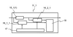
- FIG. 1 is a block diagram showing the configuration of a computer system according to the first embodiment of the invention.
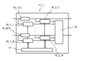
- FIG. 2 is a block diagram showing the configuration of the computing section in the computer system according to the first embodiment of the present invention.
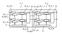
- FIG. 3A is a diagram for explaining expansion and contraction of a computing unit in the computer system according to the first embodiment of the present invention;
- FIG. 3B is a diagram for explaining expansion and contraction of a computing unit in the computer system according to the first embodiment of the present invention;
- FIG. 4A is a flow chart diagram for explaining the control method of the computer system according to the first embodiment of the present invention.
- FIG. 4B is a flow chart for explaining the computer system control method according to the first embodiment of the present invention.
- FIG. 4C is a diagram for explaining the control method of the computer system according to the first embodiment of the present invention.
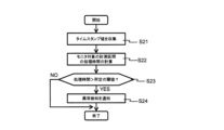
- FIG. 5 is a flow chart diagram for explaining the control method of the computer system according to the second embodiment of the present invention.
- FIG. 6 is a flow chart diagram for explaining the control method of the computer system according to the third embodiment of the present invention.
- FIG. 7A is a diagram for explaining an example of a computer system control method according to the first embodiment of the present invention.
- FIG. 7B is a diagram for explaining an example of a computer system control method according to the first embodiment of the present invention.
- FIG. 8 is a flow chart diagram for explaining the control method of the computer system according to the second embodiment of the present invention.
- FIG. 9 is a flow chart diagram for explaining the control method of the computer system according to the second embodiment of the present invention.
- FIG. 1 A computer system and its control method according to a first embodiment of the present invention will be described with reference to FIGS. 1 to 3.
- FIG. 1 A computer system and its control method according to a first embodiment of the present invention will be described with reference to FIGS. 1 to 3.
- FIG. 1 A computer system and its control method according to a first embodiment of the present invention will be described with reference to FIGS. 1 to 3.
- FIG. 1 A computer system and its control method according to a first embodiment of the present invention will be described with reference to FIGS. 1 to 3.
- the computer system 10 includes N arithmetic units 11_1 to 11_N (N is an integer equal to or greater than 1), an internal communication unit 13 that connects the arithmetic units 11_1 to 11_N, A host unit 12 that sets and manages operation parameters for the calculation units 11_1 to 11_N is provided.
- the calculation units 11_1 to 11_N are configured by processors, accelerators, etc., and include trace units 14_1 to 14_N.
- the tracing units 14_1 to 14_N are triggered by detection of a predetermined event at an arbitrary observation point of each computing unit 11_1 to 11_N, and change the operating frequency of each computing unit 11_1 to 11_N. Record the base event detection time.
- the trace units 14_1 to 14_N can record the event detection time for each data type or event type. Furthermore, arbitrary data may be recorded.
- the data processed by the calculation unit 11_1 is transferred to the calculation unit 11_2 via the internal communication unit 13. Subsequently, the data transfer is repeated, and the data is transferred to the calculation unit 11_N.
- a processing method for interlocking the calculation units 11_1 to 11_N there are a processing method in which a plurality of calculation units are connected in series, a processing method in which a plurality of calculation units are connected in parallel, a processing method in which both are combined, and the like.
- a desired service is provided and an application is processed by working together with a plurality of calculation units.
- the arithmetic units 11_1 to 11_N have a function of executing predetermined arithmetic processing on input data input from the outside of the computer system 10 .
- Arithmetic processing is, for example, processing to reduce/enlarge the image size when image data is input, processing to detect a specific object from the image data, processing to decrypt/encrypt the image data, etc. It is general arithmetic processing such as processing, aggregation, and combination.
- calculation units 11_1 to 11_N may be added or deleted regardless of whether the system is stopped or in operation.
- it can be realized by using an FPGA, which is a dynamically reconfigurable device, for only part of the computing unit.
- an accelerator card having a dedicated circuit specialized for specific calculations may be added.
- the host unit 12 has a function of setting and managing operation parameters for the calculation units 11_1 to 11_N, and more specifically has a function of controlling the calculation units 11_1 to 11_N and a function of storing data.
- the operation parameter is, for example, information for specifying an algorithm when switching between a plurality of algorithms in image processing, such as coefficients and threshold values in arithmetic processing.
- the host unit 12 sends circuit information for executing desired processing content to the operation unit. management of the entire computer system 10, such as setting
- the internal communication unit 13 connects the calculation units 11_1 to 11_N and has a communication function for exchanging data between the calculation units 11_1 to 11_N.
- commercial communication standards such as PCIe and Ethernet, and physical configurations that satisfy the communication standards, that is, PCIe switches and Ethernet switches, can be mentioned.
- a plurality of computing units providing computing functions are provided in the computing units 11_1 to 11_N
- a plurality of the observation points may be provided in the computing units 11_1 to 11_N.
- the computing unit 11_1 in the computer system 10 includes a plurality (N units) of computing units 15_1(1) to 15_N(1) and a tracing unit 14_1.
- the number of computing units may be one.
- the trace unit 14_1 includes event generators 16_1_1 to 16_2_N, a time stamp unit 17, and a trace buffer .
- the event generators 16_1_1 to 16_2_N are connected to the input side and the output side of the calculators 15_1(1) to 15_N(1), respectively.
- the output of the time stamp section 17 is connected to event generators 16_1_1 to 16_2_N.
- the outputs of event generators 16_1_1-16_2_N are connected to trace buffer 18 .
- the event generators 16_1_1 to 16_2_N may be arranged on either the input side or the output side of the calculators 15_1(1) to 15_N(1), and may be arranged at any location. I wish I could. Also, a plurality of trace buffers 18 may be arranged, and at least one may be arranged.
- the event generators 16_1_1 to 16_2_N are inserted in arbitrary positions of the calculation units 11_1 to 11_N, and detect events (start and end of streams) for each type of data (user ID, session ID, stream ID, service ID). , generates a trigger for recording trace data including the detection time (hereinafter referred to as "time stamp value") in a trace buffer 18, which will be described later.
- the type of data is not limited to the above, and any information that can be used for organizing data, such as header information of packets used for organizing data and information possessed by signals running in parallel with data, can be applied. .
- the time stamp unit 17 has at least one clock counter, synchronizes the plurality of event generators 16_1_1 to 16_2_N (observation points), and acquires the time with the accuracy of the operating frequency of the calculation units 11_1 to 11_N.
- the operating frequency (clock frequency) of the arithmetic units 11_1 to 11_N is usually about several nanoseconds when the function is realized using an FPGA (field-programmable gate array).
- the trace buffer 18 records trace data triggered by event detection by the event generators 16_1_1 to 16_2_N.
- the trace data includes each detection time (time stamp value) obtained from the time stamp unit 17, an instance ID, an event type (event ID), a data type (TID), and arbitrary data.
- the trace data should have at least a timestamp value.
- the trace buffer 18 provides a constant amount of buffer, independent of the number of event generators.
- the timestamp value is a value unified within the computing unit (FPGA).
- the instance ID is an ID that distinguishes the event generator instance and indicates the location (observation point) where the event is detected.
- event ID is an ID that distinguishes event contents. For example, the distinction is made by passing the beginning of the stream or passing the end of the stream. Also, an event detection flag or the like is prepared at an arbitrary location of the data to detect that the flag has passed.
- Arbitrary data is data that is usually processed by a computer system, such as image data, numerical data, and text data.
- the data type is used, for example, to identify and classify the attributes of input data, and is information attached to the data itself, such as user ID, session ID, stream ID, and service ID. Also, the information for identifying the data type does not necessarily have to be added to the header of the packet, and may be uniquely defined in the payload of the packet, for example. Further, when a signal running parallel to data is used inside the arithmetic unit, the parallel running signal may be used to acquire the data type.
- Input data is composed of various elements and includes an event type (event ID), a data type (TID), and arbitrary data.
- the data processed by the calculator 15_1(1) of the calculator 11_1 is transmitted and input to the calculator 15_1(2) of the calculator 11_2.
- control signals (operations) of data to be input to the arithmetic units 11_1 to 11_N are observed.
- event generators 16_1_1 to 16_2_N detect an event
- the event generators 16_1_1 to 16_2_N acquire the event type, data type, and arbitrary data from the input data.
- event occurrence is, for example, when the head of the stream has passed or when the head of the stream has passed.
- the event generators 16_1_1 to 16_2_N add the instance ID and the time stamp value transmitted from the time stamp unit 17 to the acquired event type, data type, and arbitrary data.
- the trace data consists of a timestamp value, an instance ID, an event type, a data type, and arbitrary data.
- the trace data should include at least the timestamp value, and information in the computer system such as the processing time and data flow rate can be grasped based on the timestamp value. Also, the time when the problem occurred can be grasped.
- the trace data has an instance ID, so it is possible to grasp the location where the problem occurred.
- the trace data has an event type, so it is possible to grasp when the event occurred.
- the trace data has data types, so that the operating status for each data type can be grasped, and can be used for determination (described later) at the time of data deletion.
- trace data can be used when resuming processing (described later) by having arbitrary data.
- trace data can be used to manage trace data based on priority by having service priority information.
- event generators 16_1_1-16_2_N send the trace data to the trace buffer 18.
- the time stamp unit 17 receives (writes) the count start or stop setting transmitted from the host unit 12 .
- the clock counter is set to start or stop counting.
- Counting is started by the count start setting, and the counting is performed based on the operating frequencies of the respective calculation units 11_1 to 11_N. On the other hand, counting is stopped by the count stop setting.
- the event generators 16_1_1 to 16_2_N detect an event, they read the time counted by the clock counter as a timestamp value, and the timestamp value is sent to the event generators 16_1_1 to 16_2_N.
- event detection is determined by, for example, ON/OFF of a signal that indicates whether or not the data is valid among the signals that run in parallel with the data, or a field for event detection is set in a specific area of the data.
- the event is detected by preparing and using the bit string of the field.
- calculation units are synchronized as necessary.
- synchronization is achieved by inputting a signal for synchronization or a reset signal from the host unit to the operation units to be synchronized.
- the host unit 12 when reading trace data from the trace buffer 18, the host unit 12 sends a reset signal to the time stamp unit 17 to reset the value of the clock counter.
- the trace data received from the event generators 16_1_1 to 16_2_N are recorded and accumulated in the trace buffer 18.
- trace data transmitted from a plurality of event generators 16_1_1 to 16_2_N are recorded.
- writing and reading of trace data are executed by FIFO (First-In First-Out) common to all TIDs.
- FIFO First-In First-Out
- the host unit 12 reads the trace data from the trace buffer 18.
- the host unit 12 executes post-processing of the read (collected) data. Specifically, a search (GREP) is performed for each TID. Subsequently, they are visualized after being sorted by the time stamp section 17 .
- GREP search
- the event generator acquires the event type, data type, and arbitrary data from the input data when an event is detected.
- the computer system 10 can be operated by obtaining at least the time stamp value.
- calculation units 11_1 to 11_N can be added or deleted regardless of whether the computer system 10 is stopped or in operation.
- the computing units 15_1(1) to 15_N(1) can be eliminated.
- a plurality of event generators 16_1_1 to 16_2_N can be arranged at arbitrary locations in the trace units 14_1 to 14_N.
- the event generators 16_1_1 to 16_2_N may be arranged both before the input stage and after the output stage of the calculators 15_1(1) to 15_N(1). can be placed in
- the event generators 16_1_1 to 16_2_N before and after the calculators 15_1(1) to 15_N(1) may be deleted in the trace units 14_1 to 14_N.
- both event generators before the input stage and after the output stage of the arithmetic units 15_1(1) to 15_N(1) to be deleted may be deleted, and either the event generator before the input stage or the stage after the output stage may be deleted. You can remove event generators.
- a plurality of event generators can be added at any location, by newly adding only the event generator, it is possible to easily add a new arithmetic unit inside the arithmetic unit. Measurement of processing time and collection of trace data are possible.
- the circuit scale when adding a computing unit, the circuit scale can be reduced and power consumption can be suppressed compared to adding all of the event generator, time stamp unit, and trace buffer.
- the event generators placed before and after the computing unit may be deleted.
- trace data related to the event generator may be deleted.
- the trace data attached to the event detected by the event generator to be deleted does not necessarily have to be deleted.
- the trace data recorded by the trace units 14_1 to 14_N of the calculation units 11_1 to 11_N are used to efficiently resume processing when a failure occurs.
- the defect includes a packet loss that can normally occur, a stack of processing in the internal functional blocks of the arithmetic units 11_1 to 11_N, and the like.
- the trace unit 14_1 of the calculation unit 11_1 stores a time stamp value, an instance ID (information indicating a location where an event is detected), and arbitrary data as arbitrary trace data in the trace buffer 18. Record.
- the host unit 12 monitors the trace buffer 18 of the computer system at a predetermined cycle and measures the processing time in the arithmetic unit (step S11A).
- the host unit 12 sets the event generator 16_1_1 (first event generator) on the input side of the arithmetic unit 15_1(1) and the event generator 16_1_1 (first event generator) on the output side of the arithmetic unit 15_1(1).
- 16_2_1 second event generator
- 16_2_1 reads the first time stamp value and the second stamp value triggered by the detection of each predetermined event (first event, second event) from the trace buffer 18 ( get).
- the host unit 12 calculates the processing time from the difference between the first timestamp value and the second stamp value.
- the processing time of an arbitrary point is obtained by inputting each of the event generators arranged in an arbitrary point (interval, eg, before and after computing element 15_1(1)). It is obtained by the difference between the times (the first time stamp value and the second stamp value) at which the data passes.
- the measured processing time is compared with a predetermined threshold (step S12A). As a result, if the processing time is longer than a predetermined threshold, it is determined that a problem has occurred.
- step S13A the process detection point is grasped from the instance ID, and processing is restarted using arbitrary data recorded in any of the trace buffers 18 preceding the process detection point.
- the calculation units 11_1 to 11_N record trace data and monitor the trace buffer 18 at a predetermined cycle. , until the data is input to the arithmetic unit 15_1(2) of the next-stage arithmetic unit (for example, the arithmetic unit 11_2) (hereinafter referred to as “processing time between arithmetic units”) is measured (step S11B). .
- the event generator 16_2_1 in the preceding stage of the trace buffer 18 of the calculation unit 11_1 acquires a time stamp value (first stamp value), It is recorded in the trace buffer 18 of the calculation unit 11_1.
- a notification signal is transmitted from the trace buffer 18 of the computing unit 11_1 to the computing unit 15_1(2) of the computing unit 11_2 (dotted arrow in the figure), and this signal triggers the computing unit 15_1(1) of the computing unit 11_1. , is transferred to the calculator 15_1(2) of the calculator 11_2.
- the event generator 16_1_1 preceding the computing unit 15_1(2) of the computing unit 11_2 generates the timestamp value (second stamp value) is acquired and recorded in the trace buffer 18 of the calculation unit 11_2.
- the processing time between the calculation units is measured from the difference between the first stamp value and the second stamp value.
- the measured processing time is compared with a predetermined threshold (step S12B). As a result, if the measured time is longer than a predetermined threshold, it is determined that a problem has occurred.
- an event generator placed at an arbitrary position detects a predetermined event.
- An event generator placed at a position similarly acquires other time stamp values, calculates the difference between one time stamp value and another time stamp value, determines the occurrence of a failure, and performs processing. resume.
- the process can be operated normally without restarting from the beginning. Processing can be restarted by going back to the point where the error occurred.
- the host unit 12 manages the trigger for resuming the trace data processing. Alternatively, it may be managed by the calculation units 11_1 to 11_N.
- the trace data may have data type and event type. Also, trace data may be recorded for each data type or event type.
- ⁇ Second embodiment> A computer system control method according to a second embodiment of the present invention will be described with reference to FIG.
- the trace units 14_1 to 14_N of the calculation units 11_1 to 11_N are used to perform system quality control (state management/health check).
- the trace unit 14_1 of the calculation unit 11_1 includes a plurality of event generators 16_1_1 to 16_2_N.
- FIG. 5 shows a flowchart of the control method of the computer system 10 according to this embodiment.
- the computing unit 11_1 of the computer system 10 uses a plurality of event generators 16_1_1 to 16_2_N to collect times when data passes through each of the event generators 16_1_1 to 16_2_N (step S21).
- the computing unit 11_1 generates a timestamp value (for example, a first timestamp value and a second timestamp value).
- step S22 by obtaining the difference between the collected first time stamp value and second time stamp value, the time required to pass through the specific section in the calculation unit 11_1, that is, the processing time is calculated (step S22).
- step S23 the processing time is compared with a preset threshold.
- step S24 if the processing time is greater than the threshold, an abnormality detection of the computer system 10 is notified.
- time analysis processing it is not necessary to perform time analysis processing on all data. For example, the time (processing time) required to pass through a specific section in the calculation units 11_1 to 11_N is observed at predetermined measurement intervals, and if it falls within a predetermined range or if the processing time is longer than a predetermined threshold value. It is possible to monitor whether the computer system is operating normally by determining whether or not there is.
- test data may be input and the time required for this data to pass through the calculation units 11_1 to 11_N may be analyzed.
- the computing unit controls the computer system, but the host unit may also control the computer system.
- the trace data may have a data type along with the timestamp value. Furthermore, it may have an instance ID, an event type, and arbitrary data. Also, trace data may be recorded for each data type or event type.
- ⁇ Third embodiment> A method of controlling the computer system 10 according to the third embodiment of the present invention will be described with reference to FIG.
- flow management of the computer system 10 is executed using the trace units 14_1 to 14_N of the calculation units 11_1 to 11_N.
- the trace units 14_1 to 14_N of the calculation units 11_1 to 11_N record the time stamp value and the instance ID (information indicating the location where the event is detected) as trace data in the trace buffer 18, and the host unit 12 traces. Read data.
- FIG. 6 shows a flowchart of the control method of the computer system 10 according to this embodiment.
- the host unit 12 collects, as trace data from the trace buffer 18, for example, a time stamp value and an instance ID (information indicating the location where the event is detected) obtained by the event generator 16_1 at an arbitrary location for different events. (step S31).
- the event generator 16_1 collects the time stamp values of the beginning and end stored in the trace buffer 18, which are acquired when events of passing data, such as the beginning and end, are detected as triggers.
- the difference between the leading timestamp value and the trailing timestamp value is calculated as the data passage time.
- the amount of data (data flow rate) per unit time at a predetermined location is calculated by dividing the preset amount of input data (or output data) by the data transit time (step S32). ).
- step S33 the data flow rate is compared with a preset threshold.
- the data flow (route) is set to avoid data concentration. For example, when assigning a route, the route is set by avoiding a route exceeding a predetermined threshold grasped by the instance ID (information indicating the location where the event is detected) (step S34).
- the data flow (route) can be set so as to avoid data concentration.
- the computing unit may also control the computer system.
- the host unit 12 can grasp the operating status for each data type.
- instance IDs, event types, and arbitrary data may be recorded as trace data.
- trace data may be recorded for each data type or event type.
- input data is observed by the event generator 16_1_1 in the preceding stage of the calculator 15_1(1), and input data is observed by the event generator 16_2_1 in the subsequent stage.
- the time stamp value of the top of the input data is acquired by the event generator 16_1_1 as an event trigger.
- the time stamp value of the end of the input data is acquired by the event generator 16_1_1.
- the time stamp value of the head of the output data is acquired by the event generator 16_2_1.
- the event generator 16_2_1 acquires the time stamp value of the end of the output data.
- FIG. 7A shows timestamp values (Timestamp:Dec, Timestamp:0x), instance ID (Ins), event ID (Evt), decoded event ID (Dec), TID, and event data (EventData).
- H indicates the beginning of data and L indicates the end of data.
- the data volume of the input data and output data is 1MB. Further, the operating frequency of the arithmetic units 11_1 to 11_N is 250 MHz, 4 ns/cycle).
- the timestamp value (Timestamp: Dec) at the beginning of the input data is "406514", and the instance ID (Ins) is "10" (the upper part of the dotted square 41). Also, "HR-" of the event ID (Dec) indicates the passing of the head of the data as event occurrence.
- time stamp value (Timestamp: Dec) at the beginning of the output data is "401656", and the instance ID (Ins) is "11" (the lower part of the dotted square 41). Also, "HR-" of the event ID (Dec) indicates the passing of the head of the data as event occurrence.
- the timestamp value (Timestamp: Dec) at the end of the input data is "547791", and the instance ID (Ins) is “10" (the upper part of the dotted square 42). Also, “-LR-" of the event ID (Dec) indicates passage of the end of data as event occurrence.
- time stamp value (Timestamp: Dec) at the beginning of the output data is "547794”
- instance ID (Ins) is "11" (the lower part of the dotted square 42).
- “-LR-" of the event ID (Dec) indicates passage of the end of data as event occurrence.
- FIG. 7B schematically shows the relationship between the input data 43 and the output data 44.
- the input throughput that is, the data flow rate can be calculated from the difference (arrow 46) between the end time stamp value and the beginning time stamp value of the output data 44.
- the data flow rate is obtained by dividing the data amount by the difference between the beginning and end of the time stamp value of the data.
- the difference between the time stamp values at the start of output and the start of input that is, the time stamp value at the beginning of the output data 44 (401656 cycles) and the time stamp value at the beginning of the input data 43 (401564 cycles).
- the difference gives 92 cycles.
- the processing time for input data is obtained from the difference between the time stamp values at the start of output and the start of input.
- the time stamp values of input data and output data can be used to obtain the data processing time and data flow rate.
- processing can be restarted from the middle. As a result, there is no need to repeat the already executed process from the beginning. Moreover, the processing time can be shortened when the processing is not completed normally.
- the host unit 12 can centrally manage the state of each operation unit, for example, it is possible to set a flow of data that does not pass through an operation unit whose processing has stopped, and reduce the number of data for which processing is not normally completed.
- the trace units 14_1 to 14_N are provided independently of the calculation unit, the abnormal state of the calculation unit can be retained.
- the flow can be managed at the granularity of each user (per session).
- an event generator that detects events can be inserted in any part, it is possible to detect defects that occur only in specific flows.
- a computer system and its control method according to a second embodiment of the present invention will be described with reference to FIG.
- a computer system 10 according to the present embodiment has a configuration similar to that of the first embodiment.
- the trace buffer 18 overflows, making it difficult to record trace data. Therefore, it is necessary to erase the trace data.
- FIG. 8 shows a flowchart of the computer system control method according to this embodiment.
- At least the data type is recorded as trace data in the trace buffer 18 along with the time stamp value.
- instance IDs, event types, and arbitrary data may be recorded as trace data.
- trace data may be recorded for each data type or event type.
- the host unit 12 monitors the trace buffers 18 of the calculation units 11_1 to 11_N at predetermined intervals (step S51).
- step S52 it is determined whether or not a plurality of trace data for the same data type are recorded in the trace buffer 18 (step S52).
- step S53 the event detection time recorded in the trace buffer is erased based on the event detection time.
- the power consumption of the arithmetic unit can be reduced and power efficiency can be improved.
- trace data for each data type (user ID, session ID, stream ID, service ID)
- trace data for a specific data type (for example, the highest priority service) can be retained for a relatively long time. It is possible to provide a highly flexible computer system, such as increasing reliability by doing so.
- the present embodiment naturally has the same effect as the first embodiment.
- a computer system and its control method according to Modification 1 of the second embodiment of the present invention will be described.
- a computer system 10 according to this modification has a configuration similar to that of the first embodiment.
- At least the data type is recorded as trace data in the trace buffer 18 along with the time stamp value.
- instance IDs, event types, and arbitrary data may be recorded as trace data.
- trace data may be recorded for each data type or event type.
- the arithmetic units 11_1 to 11_N of the computer system 10 record (write) the trace data (latest trace data) received from the event generators 16_1_1 to 16_2_N in the trace buffer 18, determines whether or not trace data of the same data type as the latest trace data is recorded in the trace data already held by .
- a flag or the like may be added to prevent overwriting, and whether overwriting is possible or not may be determined based on the presence or absence of the flag.
- a computer system and its control method according to Modification 2 of the second embodiment of the present invention will be described.
- a computer system 10 according to this modification has a configuration similar to that of the first embodiment.
- At least a time stamp value is recorded in the trace buffer 18 as trace data.
- data type, instance ID, event type, and arbitrary data may be recorded as trace data.
- trace data may be recorded for each data type or event type.
- the data processed by the arithmetic unit 15_1(1) is transmitted from the arithmetic unit 15_1(1) of the arithmetic unit 11_1 in the preceding stage to the arithmetic unit 15_1(2) of the arithmetic unit 11_2 in the subsequent stage. .
- the post-stage calculation unit 11_2 sends a reception completion notification to the pre-stage calculation unit 11_1.
- the preceding stage computing section 11_1 receives the reception completion notification from the succeeding stage computing section 11_2, it erases the data in the trace buffer 18 of the preceding stage computing section 11_1.
- the computing unit 11_2 in the subsequent stage may send a reception completion notification to the host unit 12 and erase the data in the trace buffer 18 of the computing unit 11_1 in the preceding stage according to the instructions of the host unit 12 .
- the host unit 12 having a larger storage capacity than the trace buffer 18 collects and records data in the trace buffer 18, data collection or the completion of collection by the host unit 12 triggers , the data in the trace buffer 18 may be erased.
- the data in the trace buffer 18 may be erased when a preset time elapses.
- a computer system and its control method according to a third embodiment of the present invention will be described.
- a computer system 10 according to the present embodiment has a configuration similar to that of the first embodiment.
- FIG. 9 shows a flowchart of a computer system control method according to this embodiment.
- the host unit 12 sets a predetermined value as the initial value of the timestamp value (step S61).
- time stamp value when the calculation units 11_1 to 11_N start measuring the input data may be used as the initial value.
- the host unit 12 may write the start of counting to the time stamp unit 17, and the time stamp value at the start of counting may be used as the initial value.
- each computing unit 11_1 to 11_N obtains a time stamp value (step S62).
- the host unit 12 compares the acquired timestamp value with a predetermined reference value for the timestamp value (step S63).
- a predetermined reference value for the timestamp value is set in advance.
- the predetermined reference value indicates the allowable range of deviation of the time stamp value from a predetermined value, eg, the initial value.
- the host unit 12 resets the time stamp values of the computing units 11_1 to 11_N to a predetermined value, such as an initial value. (step S64).
- the time stamp value is unified. Since trace data can be handled, it can be easily analyzed after collection of trace data.
- the host unit 12 centrally sets the time stamp value to a predetermined value, for example, an initial value at the start of measurement or the like, it is possible to easily correct the deviation of the clock counters between the calculation units.
- the present embodiment naturally has the same effect as the first embodiment.
- a computer system and its control method according to Modification 1 of the third embodiment of the present invention will be described.
- a computer system 10 according to this modification has a configuration similar to that of the first embodiment.
- the host unit 12 adjusts the differences in the operating frequencies of the arithmetic units 11_1 to 11_N.
- the host unit 12 can generate the time stamp of the arithmetic unit 11_1.
- the time stamp values of the calculation units 11_1 and 11_2 are synchronized.
- the host unit 12 may synchronize the time stamp values of the computing units 11_1 and 11_2 by multiplying the time stamp value of the computing unit 11_2 by 1/2.
- a conversion reference value (eg, 100 MHZ) may be provided, and the counter values of all calculation units may be converted according to the reference value of 100 MHZ.
- the host unit controls the operating frequency of one arithmetic unit (for example, the arithmetic unit 11_1) to the operating frequency of another arithmetic unit (for example, the arithmetic unit 11_2).
- the time stamp value of the other computing unit eg, the computing unit 11_2
- a coefficient set in the other computing unit eg, the computing unit 11_2
- the operating frequencies of the other computing units eg, the computing unit 11_2
- a plurality of other calculation units may be provided. In this way, the difference between the counter values that differ for each calculation unit is adjusted.
- a computer system and its control method according to Modification 2 of the third embodiment of the present invention will be described.
- a computer system 10 according to this modification has a configuration similar to that of the first embodiment.
- a different conversion value (coefficient) is set in advance according to the frequency for each calculator. For example, if the frequency of the calculation unit 11_1 is 100 MHZ and the frequency of the calculation unit 11_2 is 200 MHZ, and the reference value is 100 MHZ, the conversion value (coefficient) of the calculation unit 11_1 is “1” and the conversion value of the calculation unit 11_2 is “1”. (coefficient) is "1/2".
- the same conversion may be performed when reading the clock counter value.
- the operating frequency of one arithmetic unit (for example, arithmetic unit 11_1) is changed to another arithmetic unit (for example, , arithmetic unit 11_2) are multiplied by a coefficient set in another arithmetic unit (for example, arithmetic unit 11_2) by the time stamp value of the other arithmetic unit (for example, arithmetic unit 11_2).
- a plurality of other calculation units may be provided. In this way, the difference between the counter values that differ for each calculation unit is adjusted.
- the computing unit in the computing unit may perform the processing, or measurement and determination may be performed separately in the computing unit. You may provide processing functions, such as.
- the present invention can be applied to computer systems in the information processing field.
Landscapes
- Engineering & Computer Science (AREA)
- Theoretical Computer Science (AREA)
- Computer Hardware Design (AREA)
- General Engineering & Computer Science (AREA)
- Physics & Mathematics (AREA)
- General Physics & Mathematics (AREA)
- Quality & Reliability (AREA)
- Debugging And Monitoring (AREA)
Abstract
L'invention concerne un procédé de commande d'un système informatique qui est destiné à un système informatique qui comprend une pluralité d'unités arithmétiques (11_1 à 11 _N) et une unité hôte (12) et dans laquelle la pluralité d'unités arithmétiques comprennent chacune un tampon de trace (18) et, avec la détection d'événements prescrits à partir de données d'entrée servant de déclencheurs, des temps de détection d'événement acquis sur la base des fréquences de fonctionnement des unités arithmétiques sont enregistrés dans les tampons de trace par type de données d'entrée. Ce procédé de commande de système informatique comprend : une étape dans laquelle l'unité hôte ou les unités arithmétiques déterminent les types de données d'entrée auxquels appartiennent les temps de détection d'événement enregistrés dans les tampons de trace ; et une étape dans laquelle, en fonction du résultat de la détermination, le temps de détection d'événement le plus récent parmi les temps de détection d'événement appartenant au même type de données d'entrée est enregistré et tout autre temps de détection d'événement autre que ledit temps de détection d'événement le plus récent est effacé. La présente invention est ainsi apte à fournir un procédé de commande pour un système informatique grâce auquel un débordement de tampon peut être supprimé et la taille de tampon physique est réduite.
Priority Applications (1)
| Application Number | Priority Date | Filing Date | Title |
|---|---|---|---|
| PCT/JP2021/041778 WO2023084749A1 (fr) | 2021-11-12 | 2021-11-12 | Système informatique et procédé de commande associé |
Applications Claiming Priority (1)
| Application Number | Priority Date | Filing Date | Title |
|---|---|---|---|
| PCT/JP2021/041778 WO2023084749A1 (fr) | 2021-11-12 | 2021-11-12 | Système informatique et procédé de commande associé |
Publications (1)
| Publication Number | Publication Date |
|---|---|
| WO2023084749A1 true WO2023084749A1 (fr) | 2023-05-19 |
Family
ID=86335432
Family Applications (1)
| Application Number | Title | Priority Date | Filing Date |
|---|---|---|---|
| PCT/JP2021/041778 WO2023084749A1 (fr) | 2021-11-12 | 2021-11-12 | Système informatique et procédé de commande associé |
Country Status (1)
| Country | Link |
|---|---|
| WO (1) | WO2023084749A1 (fr) |
Citations (3)
| Publication number | Priority date | Publication date | Assignee | Title |
|---|---|---|---|---|
| JP2012252636A (ja) * | 2011-06-06 | 2012-12-20 | Fuji Electric Co Ltd | トレース情報管理装置、トレース情報管理方法、およびトレース情報管理プログラム |
| US20120331354A1 (en) * | 2009-04-29 | 2012-12-27 | Freescale Semiconductor, Inc. | Trace messaging device and methods thereof |
| WO2018182782A1 (fr) * | 2017-03-29 | 2018-10-04 | Google Llc | Traçage de matériel distribué |
-
2021
- 2021-11-12 WO PCT/JP2021/041778 patent/WO2023084749A1/fr unknown
Patent Citations (3)
| Publication number | Priority date | Publication date | Assignee | Title |
|---|---|---|---|---|
| US20120331354A1 (en) * | 2009-04-29 | 2012-12-27 | Freescale Semiconductor, Inc. | Trace messaging device and methods thereof |
| JP2012252636A (ja) * | 2011-06-06 | 2012-12-20 | Fuji Electric Co Ltd | トレース情報管理装置、トレース情報管理方法、およびトレース情報管理プログラム |
| WO2018182782A1 (fr) * | 2017-03-29 | 2018-10-04 | Google Llc | Traçage de matériel distribué |
Non-Patent Citations (1)
| Title |
|---|
| 田仲顕至ほか. 分散深層学習を高速化させるFPGA Ring-Allreduceの検討. 第82回(2020年)全国大会講演論文集(1). 20 February 2020, pp. 1-31 to 1-32 (7A-01), (Proceedings of the 82nd National Convention of IPSJ), non-official translation (TANAKA, Kenji et al. Study of FPGA Ring-Allreduce for Accelerating Distributed Deep Learning.) * |
Similar Documents
| Publication | Publication Date | Title |
|---|---|---|
| US7860965B1 (en) | System and method for network traffic and I/O transaction monitoring of a high speed communications network | |
| US11855901B1 (en) | Visibility sampling | |
| Kandula et al. | The nature of data center traffic: measurements & analysis | |
| US10673770B1 (en) | Intelligent packet queues with delay-based actions | |
| US11665104B1 (en) | Delay-based tagging in a network switch | |
| US9961000B2 (en) | Estimation of network path segment delays | |
| US8639986B2 (en) | Firmware tracing in a storage data communication system | |
| JP5686020B2 (ja) | 監視システム | |
| US20090157768A1 (en) | Computer system and data loss prevention method | |
| US9954748B2 (en) | Analysis method and analysis apparatus | |
| CN103997432A (zh) | 一种支持量化分析OpenFlow应用性能的测量系统及其方法 | |
| EP3460769B1 (fr) | Système et procédé pour gérer des alertes à l'aide d'une machine d'état | |
| WO2023084749A1 (fr) | Système informatique et procédé de commande associé | |
| WO2023084750A1 (fr) | Système informatique et procédé de commande associé | |
| WO2023084748A1 (fr) | Système informatique et procédé de commande associé | |
| US11595273B2 (en) | Measuring metrics of a computer network | |
| Miravalls-Sierra et al. | Online detection of pathological TCP flows with retransmissions in high-speed networks | |
| US11050653B2 (en) | Telemetry capture system for storage systems | |
| US11265237B2 (en) | System and method for detecting dropped aggregated traffic metadata packets | |
| Qureshi et al. | Fathom: Understanding Datacenter Application Network Performance | |
| JP6672751B2 (ja) | パケット収集方法、パケット収集プログラム及びパケット収集装置 | |
| Kissel et al. | Scalable integrated performance analysis of multi-gigabit networks | |
| Ficara et al. | A cooperative PC/Network-Processor architecture for multi gigabit traffic analysis | |
| JP5997062B2 (ja) | ネットワークシステム及びネットワーク管理装置 | |
| US11968129B1 (en) | Delay-based tagging in a network switch |
Legal Events
| Date | Code | Title | Description |
|---|---|---|---|
| 121 | Ep: the epo has been informed by wipo that ep was designated in this application |
Ref document number: 21964104 Country of ref document: EP Kind code of ref document: A1 |