WO2023084734A1 - インサータ - Google Patents
インサータ Download PDFInfo
- Publication number
- WO2023084734A1 WO2023084734A1 PCT/JP2021/041727 JP2021041727W WO2023084734A1 WO 2023084734 A1 WO2023084734 A1 WO 2023084734A1 JP 2021041727 W JP2021041727 W JP 2021041727W WO 2023084734 A1 WO2023084734 A1 WO 2023084734A1
- Authority
- WO
- WIPO (PCT)
- Prior art keywords
- inserter
- slit
- medical device
- cylindrical portion
- proximal
- Prior art date
- Legal status (The legal status is an assumption and is not a legal conclusion. Google has not performed a legal analysis and makes no representation as to the accuracy of the status listed.)
- Ceased
Links
Images








Classifications
-
- A—HUMAN NECESSITIES
- A61—MEDICAL OR VETERINARY SCIENCE; HYGIENE
- A61M—DEVICES FOR INTRODUCING MEDIA INTO, OR ONTO, THE BODY; DEVICES FOR TRANSDUCING BODY MEDIA OR FOR TAKING MEDIA FROM THE BODY; DEVICES FOR PRODUCING OR ENDING SLEEP OR STUPOR
- A61M25/00—Catheters; Hollow probes
- A61M25/01—Introducing, guiding, advancing, emplacing or holding catheters
- A61M25/09—Guide wires
Definitions
- the present invention relates to an inserter.
- Patent Document 1 discloses a catheter introduction device as an inserter used to assist in inserting a catheter into a blood vessel.
- Patent Literature 2 discloses an endoscope insertion aid as an inserter used to assist in inserting a tube into a channel of an endoscope.
- the catheter is inserted into the blood vessel by inserting the catheter from the rear end of the inserter and sending it out from the tip while the tip of the inserter is placed in the blood vessel.
- a medical device such as a guide wire
- a medical device such as a guidewire is often provided with a small curved shape (hereinafter also referred to as a “curved portion”) at its tip in order to improve blood vessel selectivity.
- the curved portion interferes with the operation of inserting the medical device from the rear end of the inserter. There was a problem of causing damage to the
- the inserter disclosed in Patent Document 2 since the tube is inserted into the inserter from the side surface of the inserter for use, insertion from the rear end of the inserter is not considered at all.
- the present invention has been made to solve the above-described problems, and an object of the present invention is to provide an inserter that can easily insert a medical device having a curved portion at its distal end.
- the present invention has been made to solve at least part of the above problems, and can be implemented as the following forms.
- an inserter is provided.
- This inserter is an inserter for assisting insertion of a medical device, and includes a flat portion having a flat shape and an elongated cylindrical portion provided on the distal end side of the flat portion.
- the shaped portion has a proximal side opening provided at the proximal end and a distal side opening provided at the distal end, and the proximal side opening and the distal side opening are provided on the side surface of the cylindrical portion. and a slit that communicates the inside and outside of the tubular portion. and is transitioning.
- the side surface of the cylindrical portion of the inserter is provided with a slit that connects the proximal side opening and the distal side opening and that communicates the inside and outside of the cylindrical portion. Therefore, as a medical device, for example, when a guide wire having a curved portion at its distal end is inserted into an inserter, a portion of the guide wire on the proximal side of the curved portion (a linear portion that is not curved) is cut into a slit. After inserting the guide wire into the inserter while pressing it over its entire length, the curved portion can be straightened and stored in the inserter by pulling the guide wire toward the proximal end side.
- the medical device can be easily inserted into the inserter as compared with the case where a medical device such as a guide wire having a curved portion at the distal end is inserted from the rear end of the inserter.
- the inserter includes a flat portion having a flat shape, and the cross-sectional shape of the cylindrical portion at the proximal end transitions from the flat shape to the cylindrical shape from the proximal end to the distal end. are doing. Therefore, before pressing a medical device such as a guide wire against the slit, the medical device can be placed on the flat portion and positioned by the base end portion of the cylindrical portion.
- the width of the slit is widened in order to remove the medical device. It can be inserted into an inserter. In this respect as well, according to the inserter with this configuration, the medical device can be easily inserted into the inserter.
- the flat portion may be curved in a direction away from the axis of the inserter from the distal side to the proximal side.
- the inserter when the inserter is placed on a flat surface, there is a high possibility that the periphery of the base end of the cylindrical portion of the inserter will be in a state of floating from the plane due to the curvature of the flat portion. As a result, the inserter placed on the flat surface can be easily picked up. In addition, when the inserter is placed on the backing paper having a curved surface that receives the curvature of the flat portion, the inserter can be stably placed.
- the cylindrical portion has a first end and a second end facing each other across the slit in any cross section, and the first end and the It may be circumferentially spaced apart from the second end. According to this configuration, the first end and the second end are spaced apart in the circumferential direction. Therefore, the medical device can be easily fitted into the slit from the outside of the inserter, and the medical device can be easily positioned by the slit. In addition, it is possible to reduce the force required to widen the slit by pressing the medical device (widening to the extent that the medical device can be inserted into the inserter).
- the cylindrical portion has a first end and a second end facing each other across the slit in any cross section, and the first end and the It may overlap with the second end. According to this configuration, the first end and the second end overlap each other. Therefore, when the medical device is inserted into the inserter, the entire periphery of the medical device is covered by the inserter, thereby preventing the medical device from popping out of the inserter.
- the flat portion and the cylindrical portion may be formed from one sheet member. According to this configuration, the manufacturing process of the inserter can be labor-saving as compared with the case where the inserter is manufactured by connecting the flat portion and the cylindrical portion formed from separate members. In addition, since there is no connecting portion due to connecting members, it is possible to realize an inserter that is difficult to break.
- the sheet member is made of uniaxially stretched PTFE resin, and the stretching direction of the PTFE resin is the same as the stretching direction of the slit extending from the proximal opening to the distal opening. They may be parallel.
- the sheet member is made of uniaxially stretched PTFE resin.
- a sheet member is cut out from uniaxially stretched PTFE resin, and the inserter is formed from the sheet member.
- the molecules in the resin are oriented along the stretching direction, so cutting out the sheet member along the stretching direction facilitates and speeds up the cutting operation. Therefore, it is possible to improve the manufacturing efficiency of the inserter.
- the stretching direction of the PTFE resin (in the sheet member) is parallel to the stretching direction of the slit extending from the base end side opening to the tip side opening. Therefore, it is possible to realize an inserter in which cracks are less likely to occur in the direction orthogonal to the extending direction of the slit.
- an inserter is provided.
- This inserter is an inserter for assisting insertion of a medical device, and includes a flat portion having a flat shape, and an elongated cylindrical portion provided on the distal end side of the flat portion.
- the shaped portion has a proximal side opening provided at the proximal end and a distal side opening provided at the distal end, and the proximal side opening and the distal side opening are provided on the side surface of the cylindrical portion. and connecting the inside and outside of the tubular portion, the minimum width of the slit is 0.2 mm or more and 0.6 mm or less, and the thickness of the inserter is 0.2 mm. not less than 0.5 mm and not more than 0.5 mm.
- the side surface of the cylindrical portion of the inserter is provided with a slit that connects the proximal side opening and the distal side opening and communicates the inside and the outside of the cylindrical portion. Therefore, as a medical device, for example, when a guide wire having a curved portion at its distal end is inserted into an inserter, a portion of the guide wire on the proximal side of the curved portion (a linear portion that is not curved) is slit. After inserting the guide wire into the inserter by pressing it over the entire length of the guide wire, the curved portion can be straightened and stored in the inserter by pulling the guide wire toward the proximal end side.
- the minimum width of the slit is 0.2 mm or more and 0.6 mm or less
- the thickness of the inserter is 0.2 mm or more and 0.5 mm or less. Therefore, when assisting the insertion of a medical device such as a guide wire having a diameter of 0.6 mm or more and 0.9 mm or less, the medical device can be easily inserted into the inserter, and the medical device can be removed from the inserter. It is possible to realize an inserter that is easy to remove. Further, when assisting the insertion of a medical device having a curved portion at its tip, an inserter in which the curved portion is less likely to protrude from the slit can be realized.
- the minimum width of the slit may be 0.3 mm or more and 0.4 mm or less. According to this configuration, when assisting the insertion of a medical device having a diameter of 0.6 mm or more and 0.9 mm or less and having a curved portion at the distal end, it is possible to realize an inserter in which the curved portion is less likely to protrude from the slit. can be done.
- the length from the tip of the flat portion to the tip of the tubular portion may be 110 mm or more and 130 mm or less.
- the inserter housing the medical device with the curved portion corrected to a straight shape is inserted into the cylindrical object.
- the curved portion can be released from the position (the distal end of the cylindrical portion) separated from the distal end of the flattened portion by 110 mm or more and 130 mm or less.
- the width of the slit may gradually narrow from the proximal side opening toward the distal side opening. According to this configuration, it is possible to make it more difficult for the medical device to protrude from the inserter toward the distal end side of the tubular portion.
- a guidewire kit includes the inserter according to the above aspect and a guidewire as the medical device, and the guidewire has a diameter of 0.6 mm or more and 0.9 mm or less. According to this guidewire kit, a medical device such as a guidewire can be easily inserted in the same manner as the inserter.
- a catheter kit includes an inserter according to the above aspect, a connector into which the inserter is inserted, and a catheter to which the connector is connected.
- the clearance width obtained by subtracting the maximum outer diameter of the portion is 0.10 mm or more and 0.35 mm or less.
- a medical device having a curved tip can be easily inserted. Also, the inserter can be easily inserted into the connector.
- a guide wire set comprising an inserter and a guide wire
- a catheter kit comprising an inserter and a catheter having a connector
- an inserter It can be realized in the form of a manufacturing method of
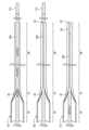
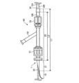
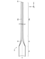
- FIG. 4 is an explanatory diagram showing a state in which the inserter is inserted into the connector; It is the top view which showed a series of extraction processes. It is the side view which showed a series of extraction processes. 1 is a table showing evaluations of Examples 1-12 and Comparative Examples 1-5. It is a top view of the inserter of 2nd Embodiment.
- FIG. 11 is a plan view of an inserter according to a third embodiment; It is a top view of the inserter of 4th Embodiment.
- FIG. 11 is a plan view of an inserter according to a fifth embodiment;
- FIG. 11 is a plan view of an inserter according to a sixth embodiment;
- FIG. 14 is a plan view of an inserter according to a seventh embodiment;
- FIG. 20 is a plan view of an inserter according to an eighth embodiment;
- FIG. 21 is a plan view of an inserter according to a ninth embodiment;
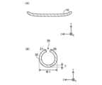
- FIG. 1 is a plan view of the inserter 1 of the first embodiment.
- FIG. 2 is a side view of the inserter 1.
- FIG. FIG. 3 is a cross-sectional view of the inserter 1.
- FIG. 3A shows a cross section taken along line A--A of FIGS. 1 and 2.
- FIG. 3B shows a cross section taken along line BB of FIGS. 1 and 2.
- FIG. 1 is a plan view of the inserter 1 of the first embodiment.
- FIG. 2 is a side view of the inserter 1.
- FIG. FIG. 3 is a cross-sectional view of the inserter 1.
- FIG. 3A shows a cross section taken along line A--A of FIGS. 1 and 2.
- FIG. 3B shows a cross section taken along line BB of FIGS. 1 and 2.
- the inserter 1 is an elongated instrument that assists in inserting a medical device such as a guidewire into an insertion target.
- the inserter 1 is used to assist in inserting a guidewire into a catheter to be inserted.
- the inserter 1 can be made of, for example, polyamide resin, polyolefin resin, polyester resin, polyurethane resin, silicon resin, fluorine resin, or the like.
- the inserter 1 is made of PTFE resin, which is a fluorine resin.
- the inserter 1 has a flat portion 10 and a tubular portion 20 .
- FIGS. 1 and 2 include portions in which the relative size ratios of the constituent members are different from the actual ones. In addition, it includes a portion exaggeratedly describing a part of each constituent member. 1 and 2 also show XYZ axes orthogonal to each other.
- the X-axis corresponds to the longitudinal direction of the inserter 1
- the Y-axis corresponds to the height direction of the inserter 1
- the Z-axis corresponds to the width direction of the inserter 1 .
- proximal side of the inserter 1 and each component
- distal side of the inserter 1 and each component
- base end of the longitudinal (X-axis) ends of the inserter 1 and each component member
- distal end and base end are referred to as the distal portion
- proximal end and the vicinity thereof are referred to as the “basal end portion”.
- the flat portion 10 is a portion that constitutes the base end side of the inserter 1 .
- the flat portion 10 has a flat shape as shown in FIG. 3(A). 2, the flat portion 10 is curved in a direction away from the axis O of the inserter 1 from the distal end side to the proximal end side.
- the tubular portion 20 is an elongated portion of the inserter 1 provided on the distal end side of the flat portion 10 .
- the cross-sectional shape of the cylindrical portion 20 at a position closer to the distal end than the proximal end portion 21 is cylindrical, as shown in FIG. 3(B).
- the cross-sectional shape of the inserter 1 taken along the line AA is flat, and the cross-sectional shape of the inserter 1 taken along the line BB is cylindrical. be.
- the cross-sectional shape of the cylindrical portion 20 at the proximal end portion 21 transitions from a flat shape to a cylindrical shape from the proximal end side to the distal end side.
- the cross-sectional shape of the cylindrical portion 20 at the proximal end portion 21 changes from a flat shape to a cylindrical shape that gradually curls from the proximal end side to the distal end side.
- the tubular portion 20 has a proximal opening 22 provided at the proximal end and a distal opening 24 provided at the distal end.
- a slit 26 is provided on the side surface of the cylindrical portion 20 to connect the proximal side opening 22 and the distal side opening 24 and communicate the inside and the outside of the cylindrical portion 20 .
- the width (length in the Z-axis direction) of the slit 26 is substantially constant at a position closer to the distal end than the proximal end portion 21 .
- the width of the slit 26 is designed to be shorter than the diameter of the medical device to be inserted into the inserter 1 (the medical device whose insertion into the insertion target is assisted).
- the tubular portion 20 has a first end portion 27 and a second end portion 28 facing each other across a slit 26 in any cross section. Also, the first end portion 27 and the second end portion 28 are spaced apart in the circumferential direction.
- the first end portion 27 and the second end portion 28 referred to here include the ends in the circumferential direction of the cross section and the vicinity thereof. Note that the thickness T and the maximum outer diameter ⁇ 1 will be described later.
- FIG. 4 is a perspective view for explaining the manufacturing process of the inserter 1.
- FIG. 4A is a perspective view of the intermediate product 1P.
- FIG. 4B is a perspective view of the inserter 1.
- FIG. 4A is a perspective view of the intermediate product 1P.
- the intermediate product 1P is a cylindrical member.
- the intermediate product 1P is manufactured by joining a pair of opposing sides of one sheet member to form a tubular shape.
- This sheet member is a sheet member cut out along the stretching direction from uniaxially stretched PTFE resin.
- the direction in which the PTFE resin is stretched is parallel to the direction in which the two sides that are joined when being molded into a cylindrical shape extend. That is, the longitudinal direction of the intermediate product 1P is parallel to the stretching direction of the PTFE resin forming the intermediate product 1P.
- a cut CT (illustrated by a broken line) is made in the side surface of the intermediate product 1P. At this time, the cut CT is made over the entire length of the intermediate product 1P.
- the intermediate product 1P is opened with a constant width (corresponding to the width of the slit 26) along the longitudinal direction to form the cylindrical portion 20. be done.
- the intermediate product 1P is widely opened to form a flat portion 10. As shown in FIG.
- the portion of the cylindrical portion 20 corresponding to the base end portion 21 is opened so that the cross-sectional shape changes from the flat shape to the cylindrical shape.
- the flat portion 10 and the tubular portion 20 are formed from a single sheet member, and the sheet member is formed from uniaxially stretched PTFE resin. Since the PTFE resin, which is the material used for the inserter 1 of the present embodiment, has relatively high plasticity, the shape after the manufacturing process is maintained even if the above-described manufacturing process is performed without applying heat in advance.
- the material used for the inserter 1 is a thermoplastic resin, it is preliminarily heated and then the above manufacturing process is carried out.
- the longitudinal direction of the intermediate product 1P is parallel to the stretching direction in the PTFE resin forming the intermediate product 1P.
- the slit 26 in the inserter 1 is formed along the longitudinal direction of the intermediate product 1P. Therefore, the extending direction of the PTFE resin forming the inserter 1 is parallel to the extending direction of the slit 26 extending from the proximal side opening 22 to the distal side opening 24 .
- FIG. 5 and 6 are explanatory diagrams showing the process of attaching the guide wire GW, which is a medical device, to the inserter 1.
- FIG. 5A to 5C are plan views showing a series of mounting processes.
- 6A to 6C are side views showing a series of mounting processes.
- the guide wire GW is a guide wire having a curved portion CV at its tip.
- medical devices such as guidewires are often provided with a small curved shape (hereinafter also referred to as a “curved portion”) at the tip in order to improve blood vessel selectivity.
- the operator places the portion of the guide wire GW closer to the proximal side than the curved portion CV on the slit 26 provided in the inserter 1. do. Then, the guide wire GW is pressed against the inserter 1 (slit 26) in order from the proximal side to the distal side (in the direction indicated by the white arrow). That is, the portion of the guide wire GW on the proximal side of the curved portion CV is pressed over the entire length of the slit 26 .
- the width of the slit 26 is designed to be shorter than the diameter of the guide wire GW, the slit 26 corresponding to the position where the guide wire GW is pressed is widened in the width direction so that the guide wire GW can be sequentially inserted into the inserter 1. take in.
- FIGS. 5(B) and 6(B) show a state in which the guide wire GW is inserted into the inserter 1 through the slit 26 through the process described in FIGS. 5(A) and 6(A). It is shown. A curved portion CV of the guide wire GW is exposed to the outside of the inserter 1 through the distal opening 24 . From this state, as shown in FIGS. 5(C) and 6(C), the operator pulls the guide wire GW toward the proximal end side to house the bending portion CV inside the inserter 1 (white line). direction indicated by the open arrow). Along with this retraction, the curved portion CV is corrected into a straight shape along the elongated inserter 1 .
- FIG. 7 is an explanatory diagram showing a state in which the inserter 1 is inserted into the connector 50.
- FIG. 7 In the state shown in FIG. 7, after the inserter 1 maintaining the state shown in FIGS. It has been delivered and inserted into the catheter CA.
- the portion of the inserter 1 that is inserted into the connector 50 is indicated by a broken line.
- a portion of the guide wire GW that is inserted into the inserter 1 is omitted from the drawing.
- the connector 50 is a connector into which the inserter 1 is inserted. Further, the connector 50 includes a first port 51 having a hemostasis valve, a second port 52 for injecting a contrast agent or the like, and a connecting portion 53 connected to the catheter hub HB. The catheter hub HB is connected to the connecting portion 53 . Catheter CA is connected to connector 50 via catheter hub HB.
- the length L1 from the distal end of the flat portion 10 to the distal end of the cylindrical portion 20 in the inserter 1 is from the proximal end of the insertion hole of the connector 50 (the hole for inserting the cylindrical portion 20 into the connector 50) to the distal end of the catheter hub HB. It is designed to be longer than the length L2. In FIG.
- the length L1 is preferably 110 mm or more and 130 mm or less.
- the tubular portion 20 can be exposed from the distal end of the catheter hub HB and placed in the catheter CA, and the tubular portion 20 can be placed inside the catheter CA.
- Curvature CV (not shown in FIG. 7) can be delivered into catheter CA by releasing the straightening from the tip.
- FIG. 8A to 8C are plan views showing a series of withdrawal processes.
- 9A to 9C are side views showing a series of withdrawal processes.
- FIGS. 8(B) and 9(B) the operator moves a finger or the like sandwiched between the flat portion 10 and the guide wire GW along the surface of the inserter 1 to the distal end side.
- the guide wire GW that has been taken into the inserter 1 is pulled out from the inserter 1 by moving (in the direction indicated by the white arrow).
- 8(C) and 9(C) show a state in which the guide wire GW has been removed from the inserter 1 through the slit 26 through the process described in FIGS. 8(B) and 9(B). It is
- the proximal side opening 22 and the distal side opening 24 are connected to the side surface of the tubular section 20, and the inside and outside of the tubular section 20 are communicated.
- a slit 26 is provided. Therefore, for example, when a guide wire GW having a curved portion CV at its distal end is inserted into the inserter 1 as a medical device (see FIGS.
- the portion of the guide wire GW on the proximal side of the curved portion CV After inserting the portion (non-curved linear portion) into the inserter 1 by pressing it over the entire length of the slit 26, the guide wire GW is pulled toward the proximal end side, thereby correcting the curved portion CV into a linear shape and inserting the inserter. 1 can be stored. Therefore, such a medical device can be easily inserted into the inserter 1 as compared with the case where a medical device such as a guide wire GW having a curved portion CV at its tip is inserted from the rear end of the inserter.
- the inserter 1 includes the flat portion 10 having a flat shape, and the cross-sectional shape of the cylindrical portion 20 at the base end portion 21 is oriented from the base end side to the tip end side. It transitions from a flat shape to a cylindrical shape. Therefore, before pressing a medical device such as a guide wire GW against the slit 26, the medical device is placed on the flat portion 10 and positioned by the base end portion 21 of the cylindrical portion 20. (See FIGS. 5A and 6A).
- the slit 26 is widened in order.
- the medical device can be inserted into the inserter 1 by using the In this respect as well, according to the inserter 1 having this configuration, a medical device such as a guide wire GW can be easily inserted into the inserter 1 .
- the inserter 1 of the first embodiment when inserting the inserter 1 into a cylindrical object (for example, the connector 50 in FIG. 7), the entire inserter 1 is inserted into the object. can be prevented. Also, when holding the inserter 1 with the flat portion 10 sandwiched between two fingers, the surface of the flat portion 10 facing the opposite side to the axis side (the -Y-axis direction side in FIG. 2) Since the contact area between the curve and the curved surface of the finger surface (the ball of the finger) is increased, the inserter 1 can be easily held.
- the inserter 1 when the inserter 1 is placed on a flat surface, there is a high possibility that the periphery of the base end portion 21 of the cylindrical portion 20 of the inserter 1 will be in a state of floating from the flat surface due to the curvature of the flat portion 10. By gripping the periphery of the end portion 21, the inserter 1 placed on a flat surface can be easily picked up.
- the inserter 1 when the inserter 1 is arranged on a mount having a surface formed with a curved surface for receiving the curvature of the flat portion 10, the inserter 1 can be stably arranged.
- the first end portion 27 and the second end portion 28 are spaced apart in the circumferential direction. Therefore, the medical device can be easily fitted into the slit 26 from the outside of the inserter 1 , and the medical device can be easily positioned by the slit 26 . In addition, the force required to widen the width of the slit 26 by pressing the medical device (widening to the extent that the medical device can be inserted into the inserter 1) can be reduced.
- the manufacturing process of the inserter 1 can be labor-saving as compared with the case where the inserter 1 is manufactured by connecting the flat portion 10 and the cylindrical portion 20 which are formed of separate members. can be In addition, since there is no connecting portion due to connecting members, the inserter 1 that is difficult to break can be realized.
- the sheet member constituting the inserter 1 is made of uniaxially stretched PTFE resin.
- a sheet member is cut out from uniaxially stretched PTFE resin, and the inserter 1 is formed from the sheet member.
- the molecules in the resin are oriented along the stretching direction, so cutting out the sheet member along the stretching direction facilitates and speeds up the cutting operation. Therefore, the manufacturing efficiency of the inserter 1 can be improved.
- the stretching direction of the PTFE resin (in the sheet member) is parallel to the stretching direction of the slits 26 extending from the proximal side opening to the distal side opening. For this reason, it is possible to realize the inserter 1 in which cracks in the direction orthogonal to the extending direction of the slits 26 are less likely to occur.
- FIG. 10 shows the results of an evaluation test that evaluated the feeling of use when a guidewire was inserted into each inserter 1 (Examples 1 to 12 and Comparative Examples 1 to 5) prepared by adjusting various parameters. is shown as a table.
- the various parameters referred to here include the minimum width W of the slit 26, the thickness T of the inserter 1 (see FIG. 3B), and the maximum outer diameter ⁇ 1 of the cylindrical portion 20 (see FIG. 3B). , is included.
- the minimum width W is the width of the slit 26 at the minimum width. It can also be said that the thickness T is the thickness of the sheet member forming the inserter 1 .
- the maximum outer diameter ⁇ 1 is the outer diameter at the position where the outer diameter is maximum in the cross section of the tubular portion 20 .
- the width of the slit 26 and the outer diameter of the tubular portion 20 are generally constant.
- guidewire diameter indicates the diameter of the guidewire inserted into the inserter 1.
- Minimum width W indicates the minimum width W of the slit 26 .
- Thiickness T indicates the thickness T of the inserter 1 .
- Maximum outer diameter ⁇ 1 indicates the maximum outer diameter ⁇ 1 of the tubular portion 20 .
- the “clearance width C” indicates the clearance width C obtained by subtracting the maximum outer diameter ⁇ 1 of the cylindrical portion 20 from the maximum inner diameter of the insertion hole of the connector 50 (the hole for inserting the cylindrical portion 20 into the connector 50).
- the maximum inner diameter is the inner diameter of the portion of the connector 50 where the inserter 1 is inserted, at the position where the inner diameter is the largest, and is 2.65 mm in FIG.
- the unit of the numerical value on the left side of the numerical values indicating "guidewire diameter” is inches, and the numerical value in parentheses on the right side is the numerical value obtained by converting the numerical value on the left side into millimeters, and the unit is millimeters.
- the unit of numerical values indicating the "minimum width W", “thickness T”, “maximum outer diameter ⁇ 1", and “clearance width C" is millimeters.
- Fig. 10 shows evaluation items for usability.
- Connector insertability indicates ease of inserting the inserter 1 into the connector 50 .
- the "slit formability” indicates the easiness of cutting in the manufacturing process of the inserter 1, when the side surface of the intermediate product 1P is cut CT (see FIG. 4(A)).
- Slit release indicates how difficult it is for the curved portion to protrude from the slit 26 when a guide wire having a curved portion at its tip is inserted into the inserter 1 (see FIGS. 5 and 6).
- Kink resistance indicates the difficulty of clogging the lumen of the inserter 1 when the inserter 1 is bent during the process of inserting the inserter 1 into the connector 50 (see FIG. 7).
- “Detachability” indicates ease of inserting a guidewire into the inserter 1 and ease of removing the guidewire from the inserter 1 .
- Each evaluation item of feeling in use was evaluated in three grades of B, C, and D.
- the "comprehensive evaluation” is a comprehensive evaluation in consideration of the evaluation items of each usability, and was evaluated in four stages of A, B, C, and D.
- the evaluation result means that A is the best and D is the worst.
- each "overall evaluation” was D.
- each "connector insertability” was evaluated as D, which is considered to be due to the numerical value of each "clearance width C" being 0.00 mm.
- the evaluation of "missing slit” was D, which is considered to be due to the numerical value of "minimum width W" being 0.7 mm.
- the evaluation of "kink resistance” was D, which is considered to be due to the numerical value of "clearance width C" being 0.55 mm.
- the minimum width W of the slit is 0.2 mm or more and 0.9 mm or more. It is 6 mm or less, and the thickness T of the inserter 1 is preferably 0.2 mm or more and 0.5 mm or less.
- the guide wire when assisting the insertion of a medical device such as a guide wire having a diameter of 0.6 mm or more and 0.9 mm or less, the guide wire can be easily inserted into the inserter 1 and It is possible to realize an inserter from which the medical device can be easily removed. Further, when assisting the insertion of a medical device such as a guide wire having a curved portion at its distal end, the inserter 1 can be realized in which the curved portion is less likely to protrude from the slit. That is, it is possible to realize an inserter excellent in "detachability" and "slit removal".
- the minimum width W of the slit is more preferably 0.3 mm or more and 0.4 mm or less. According to this configuration, when assisting the insertion of a medical device such as a guide wire having a diameter of 0.6 mm or more and 0.9 mm or less and having a curved portion at the distal end, the curved portion is less likely to protrude from the slit 26.
- the inserter 1 can be implemented.
- the clearance width C is preferably 0.10 mm or more and 0.35 mm or less. This configuration makes it easier to insert the inserter 1 into the connector 50 . That is, it is possible to realize an inserter excellent in "connector insertability" and "kink resistance”.
- the inserter 1 when the length L2 is 110 mm, the length L1 from the tip of the flat portion 10 to the tip of the tubular portion 20 in the inserter 1 is 110 mm or more and 130 mm or less. is preferred.
- the inserter accommodates the medical device with the curved portion straightened. 1 is inserted into a cylindrical object (connector 50 in FIG. 7) (see FIGS. 5 to 7), a position (the tip of cylindrical portion 20) separated from the tip of flat portion 10 by 110 mm or more and 130 mm or less.
- the straightening can be released from and the curved portion can be delivered.
- the bending portion CV (not shown in FIG. 7) can be delivered from the distal end of the tubular portion 20 placed in the catheter CA with the straightening removed.
- FIG. 11 is a plan view of the inserter 1A of the second embodiment.
- FIG. 12 is a cross-sectional view of the inserter 1A.
- FIG. 12 shows a cross section taken along line CC of FIG.
- the inserter 1A of the second embodiment differs from the inserter 1 of the first embodiment in that it has a tubular portion 20a different from the tubular portion 20 of the first embodiment.
- the tubular portion 20a has a first end portion 27a and a second end portion 28a that face each other with a slit 26a interposed therebetween and overlap each other in any cross section.
- first end portion 27 and the second end portion 28 are spaced apart in the circumferential direction (see FIG. 3B), in the plan view (FIG. 1), the cylinder
- first end 27a and the second end 28a overlap each other (see FIG. 12), so the plan view (FIG. 11 ), the inside of the cylindrical portion 20 cannot be visually recognized.
- the width of the slit 26a is widened so that the medical device can be inserted into the inserter 1A. be able to.
- the inserter 1A of the second embodiment As described above, it is possible to easily insert a medical device such as a guidewire into the inserter 1A as in the first embodiment. Further, according to the inserter 1A of the second embodiment, when the medical device is inserted into the inserter 1A, the entire periphery of the medical device is covered by the inserter 1A. can be prevented from popping out.
- FIG. 13 is a plan view of the inserter 1B of the third embodiment.
- the inserter 1B of the third embodiment differs from the inserter 1 of the first embodiment in that it has a tubular portion 20b different from the tubular portion 20 of the first embodiment.
- the width (the length in the Z-axis direction) of the slit 26b provided in the tubular portion 20b is approximately although it has a constant width, it gradually narrows toward the tip at the tip.
- a medical device such as a guide wire can be easily inserted into the inserter 1B as in the first embodiment.
- a medical device can be easily fitted from the outside of the inserter 1B into a portion of the slit 26b that has a substantially constant width (excluding the tip portion). device is easier to position.
- the tip of the slit 26b can prevent the medical device from popping out of the inserter 1B.
- FIG. 14 is a plan view of the inserter 1C of the fourth embodiment.
- the inserter 1C of the fourth embodiment differs from the inserter 1 of the first embodiment in that it has a tubular portion 20c different from the tubular portion 20 of the first embodiment.
- the width (the length in the Z-axis direction) of the slit 26c provided in the cylindrical portion 20c gradually narrows from the proximal side opening 22 toward the distal side opening 24.
- a medical device such as a guide wire can be easily inserted into the inserter 1C as in the first embodiment.
- FIG. 15 is a plan view of the inserter 1D of the fifth embodiment.
- the inserter 1D of the fifth embodiment differs from the inserter 1 of the first embodiment in that it has a tubular portion 20d different from the tubular portion 20 of the first embodiment.
- the width (the length in the Z-axis direction) of the slit 26d provided in the cylindrical portion 20d is the same as in the fourth embodiment, from the proximal side opening 22 to the distal side opening. 24 gradually becomes narrower.
- a first end (not shown) and a second end (not shown) overlap each other.
- FIG. 16 is a plan view of the inserter 1E of the sixth embodiment.
- the inserter 1E of the sixth embodiment differs from the inserter 1 of the first embodiment in that it has a tubular portion 20e different from the tubular portion 20 of the first embodiment.
- bridge portions 29 are provided at regular intervals in the slits 26e provided in the cylindrical portion 20e.
- the slit 26e does not connect the proximal-side opening 22 and the distal-side opening 24 on the side surface of the cylindrical portion 20e, and a bridging portion is formed between the proximal-side opening 22 and the distal-side opening 24. 29 are provided alternately. Even in such a cylindrical portion 20e, when a medical device such as a guide wire is pressed against the slit 26e, the cross-linking portion 29 is destroyed and then the slit 26e is widened so that the medical device can be inserted into the inserter 1E.
- the inserter 1E of the sixth embodiment As described above, it is possible to easily insert a medical device such as a guidewire into the inserter 1E as in the first embodiment.
- a medical device such as a guidewire
- the inserter 1E of the sixth embodiment since the bridging portion 29 is provided, the cylindrical portion 20e is deformed by an external force, and the diameter of the cylindrical portion 20e (the width of the slit 26e) changes when manufacturing is completed. can be prevented from shrinking from the inserter 1E.
- remnants of the bridging portion 29 remain on at least one end of the slit 26e in the width direction (the Z-axis direction in FIG. 16).
- the medical device is inside the inserter 1E, it is possible to prevent the medical device from popping out of the inserter 1E due to the wreckage.
- FIG. 17 is a plan view of the inserter 1F of the seventh embodiment.
- the inserter 1F of the seventh embodiment differs from the inserter 1 of the first embodiment in that it has a tubular portion 20f different from the tubular portion 20 of the first embodiment.
- the width (the length in the Z-axis direction) of the slit 26f provided in the cylindrical portion 20f is the same as in the fourth embodiment, from the proximal side opening 22 to the distal side opening. 24 gradually becomes narrower.
- a first end (not shown) and a second end ( (not shown) overlap each other.
- the diameter of the cylindrical portion 20f is reduced from the proximal side to the distal side.
- FIG. 18 is a plan view of the inserter 1G of the eighth embodiment.
- the inserter 1G of the eighth embodiment differs from the inserter 1 of the first embodiment in that it has a tubular portion 20g different from the tubular portion 20 of the first embodiment.
- the tubular portion 20g has the smallest diameter portion 23 at the tip.
- the smallest diameter portion 23 is a portion of the cylindrical portion 20g that has a smaller diameter than the portion on the base end side from the smallest diameter portion 23 .
- the smallest diameter portion 23 may be produced by extending the tip portion of the cylindrical portion 20 along the axis O using the inserter 1 of the first embodiment.
- the inserter 1G may be manufactured by press molding using a mold for molding the inserter 1G. With such an inserter 1G of the eighth embodiment as well, a medical device such as a guide wire can be easily inserted into the inserter 1G as in the first embodiment.
- the inserter 1G since the tubular portion 20g has the reduced diameter portion 25, the inserter 1G (tubular portion 20g) can be inserted into the catheter CA via the connector 50 (FIG. 7). When providing guidance, the guidance can be performed smoothly.
- FIG. 19 is a plan view of the inserter 1H of the ninth embodiment.
- the inserter 1H of the ninth embodiment differs from the inserter 1G of the eighth embodiment in that it has a tubular portion 20h different from the tubular portion 20g of the eighth embodiment.
- the cylindrical portion 20h has a reduced diameter portion 25 at the base end portion of the smallest diameter portion 23.
- the reduced-diameter portion 25 is a portion of the cylindrical portion 20h whose diameter gradually decreases toward the distal end side.
- the reduced diameter portion 25 and the smallest diameter portion 23 may be produced by extending the tip portion of the inserter 1 along the axis O, as in the eighth embodiment.
- the inserter 1H may be manufactured by press molding using a mold for molding the inserter 1H. With such an inserter 1H of the ninth embodiment as well, a medical device such as a guide wire can be easily inserted into the inserter 1G like the first embodiment.
- the inserter 1H of the ninth embodiment since the cylindrical portion 20h has the smallest diameter portion 23 and the reduced diameter portion 25, the inserter 1H (cylindrical portion 20h) is connected via the connector 50 (FIG. 7). ) into the catheter CA, the guidance can be performed more smoothly.
- the configurations of the inserters 1, 1A to 1H are illustrated.
- the configuration of the inserter can be modified in various ways.
- the flat portion 10 is curved in a direction away from the axis O of the inserter 1 from the distal end side to the proximal end side. It may be along the axis O.
- the flat portion 10 and the tubular portion 20 may not be formed from a single sheet member, and the flat portion 10 and the tubular portion 20 formed from separate members are connected to form the inserter 1. You may have Further, even if the flat portion 10 and the cylindrical portion 20 are formed from one sheet member, the sheet member may be formed from PTFE resin that is not uniaxially stretched.
- the inserter 1 was described as an inserter used to assist in inserting a guide wire into a catheter, but the present invention is not limited to this, and any medical device (catheter, tube, etc.) can be used in any desired manner. It may also be used to aid insertion into tubular objects (blood vessels, endoscope channels, etc.).
- the color of the inserter is set according to the cylindrical object into which the inserter is inserted and the surrounding conditions assumed when the inserter is used. For example, by setting the color of the inserter to be different from the color of the sheets spread on the bed on which the patient is lying or the color of the cylindrical object, it is possible to prevent the operator from losing sight of the inserter.
Landscapes
- Health & Medical Sciences (AREA)
- Life Sciences & Earth Sciences (AREA)
- Biophysics (AREA)
- Pulmonology (AREA)
- Engineering & Computer Science (AREA)
- Anesthesiology (AREA)
- Biomedical Technology (AREA)
- Heart & Thoracic Surgery (AREA)
- Hematology (AREA)
- Animal Behavior & Ethology (AREA)
- General Health & Medical Sciences (AREA)
- Public Health (AREA)
- Veterinary Medicine (AREA)
- Media Introduction/Drainage Providing Device (AREA)
Priority Applications (2)
| Application Number | Priority Date | Filing Date | Title |
|---|---|---|---|
| JP2023559342A JP7592192B2 (ja) | 2021-11-12 | 2021-11-12 | インサータ |
| PCT/JP2021/041727 WO2023084734A1 (ja) | 2021-11-12 | 2021-11-12 | インサータ |
Applications Claiming Priority (1)
| Application Number | Priority Date | Filing Date | Title |
|---|---|---|---|
| PCT/JP2021/041727 WO2023084734A1 (ja) | 2021-11-12 | 2021-11-12 | インサータ |
Publications (1)
| Publication Number | Publication Date |
|---|---|
| WO2023084734A1 true WO2023084734A1 (ja) | 2023-05-19 |
Family
ID=86335393
Family Applications (1)
| Application Number | Title | Priority Date | Filing Date |
|---|---|---|---|
| PCT/JP2021/041727 Ceased WO2023084734A1 (ja) | 2021-11-12 | 2021-11-12 | インサータ |
Country Status (2)
| Country | Link |
|---|---|
| JP (1) | JP7592192B2 (https=) |
| WO (1) | WO2023084734A1 (https=) |
Citations (2)
| Publication number | Priority date | Publication date | Assignee | Title |
|---|---|---|---|---|
| US4726369A (en) * | 1986-07-31 | 1988-02-23 | Advanced Cardiovascular Systems, Inc. | Tool and method for steering an angioplasty guide wire |
| JP2005253671A (ja) * | 2004-03-11 | 2005-09-22 | Terumo Corp | 長尺物導入器具 |
Family Cites Families (3)
| Publication number | Priority date | Publication date | Assignee | Title |
|---|---|---|---|---|
| JPS5412955Y2 (https=) * | 1974-02-12 | 1979-06-04 | ||
| US7740620B2 (en) * | 2005-02-08 | 2010-06-22 | Paul J. Gilbert | Insertion system and methods for nasogastric tubes including feeding tubes |
| JP5389373B2 (ja) * | 2008-04-23 | 2014-01-15 | オリンパスメディカルシステムズ株式会社 | 内視鏡用ガイドワイヤプローブ、ガイドワイヤプローブセット、及び超音波内視鏡 |
-
2021
- 2021-11-12 WO PCT/JP2021/041727 patent/WO2023084734A1/ja not_active Ceased
- 2021-11-12 JP JP2023559342A patent/JP7592192B2/ja active Active
Patent Citations (2)
| Publication number | Priority date | Publication date | Assignee | Title |
|---|---|---|---|---|
| US4726369A (en) * | 1986-07-31 | 1988-02-23 | Advanced Cardiovascular Systems, Inc. | Tool and method for steering an angioplasty guide wire |
| JP2005253671A (ja) * | 2004-03-11 | 2005-09-22 | Terumo Corp | 長尺物導入器具 |
Also Published As
| Publication number | Publication date |
|---|---|
| JP7592192B2 (ja) | 2024-11-29 |
| JPWO2023084734A1 (https=) | 2023-05-19 |
Similar Documents
| Publication | Publication Date | Title |
|---|---|---|
| CN107072671B (zh) | 内窥镜用处置器具 | |
| JP5719371B2 (ja) | カテーテル装置 | |
| EP1845872B1 (en) | Guide wire advancer assembly | |
| US11219749B2 (en) | Balloon catheter systems and methods | |
| US8317754B2 (en) | Valves and hubs for tubular devices and methods for making and using them | |
| CN102727276B (zh) | 一种组织止血夹持装置 | |
| US6551281B1 (en) | Guide wire advancer and assembly and method for advancing a guide wire | |
| JP5717884B2 (ja) | カテーテル用ガイドワイヤ導入器具 | |
| CN110292411A (zh) | 一种组织夹闭装置 | |
| EP2875787B1 (en) | Hemostatic clip | |
| JP2013505098A5 (https=) | ||
| WO2017090473A1 (ja) | 接続構造および接続方法 | |
| JP2008510579A (ja) | 予め湾曲させたカテーテルクリップ及びその使用方法 | |
| WO2017066986A1 (zh) | 连发结扎装置 | |
| JP2017099884A (ja) | 双安定構造を備える針デバイスおよび関連方法 | |
| KR102946779B1 (ko) | 카테터 삽입용 니들 장치 | |
| US20160100962A1 (en) | Medical stent | |
| CN210811306U (zh) | 一种组织夹闭装置 | |
| US7828751B2 (en) | Method and apparatus for retaining a fixation pin to a cannula | |
| JP2019520904A (ja) | 止血クリップの為の再搭載可能なアプリケータ | |
| US20050251150A1 (en) | Evulsion aid for fistula catheter and fistula catheter set | |
| CN202699219U (zh) | 一种组织止血夹持装置 | |
| WO2023084734A1 (ja) | インサータ | |
| WO2023084735A1 (ja) | インサータ、ガイドワイヤキット、及びカテーテルキット | |
| EP1800607B1 (en) | Reinforcing tool for a medical needle |
Legal Events
| Date | Code | Title | Description |
|---|---|---|---|
| 121 | Ep: the epo has been informed by wipo that ep was designated in this application |
Ref document number: 21964089 Country of ref document: EP Kind code of ref document: A1 |
|
| WWE | Wipo information: entry into national phase |
Ref document number: 2023559342 Country of ref document: JP |
|
| NENP | Non-entry into the national phase |
Ref country code: DE |
|
| 122 | Ep: pct application non-entry in european phase |
Ref document number: 21964089 Country of ref document: EP Kind code of ref document: A1 |