WO2023084646A1 - Dispositif de direction - Google Patents
Dispositif de direction Download PDFInfo
- Publication number
- WO2023084646A1 WO2023084646A1 PCT/JP2021/041371 JP2021041371W WO2023084646A1 WO 2023084646 A1 WO2023084646 A1 WO 2023084646A1 JP 2021041371 W JP2021041371 W JP 2021041371W WO 2023084646 A1 WO2023084646 A1 WO 2023084646A1
- Authority
- WO
- WIPO (PCT)
- Prior art keywords
- steering
- command value
- torque
- driver
- steering angle
- Prior art date
Links
- 238000006243 chemical reaction Methods 0.000 claims abstract description 54
- 238000004364 calculation method Methods 0.000 claims abstract description 32
- 230000033001 locomotion Effects 0.000 claims abstract description 9
- 230000000007 visual effect Effects 0.000 claims description 19
- 238000010586 diagram Methods 0.000 description 19
- 239000011159 matrix material Substances 0.000 description 19
- 230000009467 reduction Effects 0.000 description 17
- 230000007246 mechanism Effects 0.000 description 12
- 230000001133 acceleration Effects 0.000 description 10
- 230000036461 convulsion Effects 0.000 description 6
- 239000003638 chemical reducing agent Substances 0.000 description 5
- 238000013016 damping Methods 0.000 description 5
- 230000006870 function Effects 0.000 description 4
- 230000000694 effects Effects 0.000 description 2
- 238000001914 filtration Methods 0.000 description 2
- 230000005484 gravity Effects 0.000 description 2
- 238000012890 quintic function Methods 0.000 description 2
- 230000004044 response Effects 0.000 description 2
- 238000013459 approach Methods 0.000 description 1
- 230000005540 biological transmission Effects 0.000 description 1
- 230000008859 change Effects 0.000 description 1
- 238000001514 detection method Methods 0.000 description 1
- 230000004069 differentiation Effects 0.000 description 1
- 238000006073 displacement reaction Methods 0.000 description 1
- 230000010354 integration Effects 0.000 description 1
- 230000003993 interaction Effects 0.000 description 1
- 238000000034 method Methods 0.000 description 1
- 238000006557 surface reaction Methods 0.000 description 1
- 239000000725 suspension Substances 0.000 description 1
Images


Classifications
-
- B—PERFORMING OPERATIONS; TRANSPORTING
- B62—LAND VEHICLES FOR TRAVELLING OTHERWISE THAN ON RAILS
- B62D—MOTOR VEHICLES; TRAILERS
- B62D6/00—Arrangements for automatically controlling steering depending on driving conditions sensed and responded to, e.g. control circuits
Definitions
- This invention relates to a steering device.
- Patent Document 1 describes a manual steering command value calculation unit that calculates a manual steering command value using a steering torque, and an integrated angle command value that calculates an integrated angle command value by adding the manual steering command value to the automatic steering command value.
- a motor control device includes a command value calculation unit and a control unit that controls the angle of an electric motor based on an integrated angle command value.
- An object of the present invention is to provide a steering system capable of performing steering control that sufficiently reflects the driver's intention in the driving support mode.
- An embodiment of the present invention includes an electric motor for steering angle control, a manual steering angle command value calculator that calculates a manual steering angle command value based on an equation of motion including a steering torque and a reaction force control gain, and a driving assistance device.
- An integrated angle command value calculation unit that adds the manual steering angle command value to the automatic steering angle command value for the automatic steering angle command value to calculate an integrated angle command value, and angle-controls the electric motor based on the integrated angle command value.
- a steering system includes a control unit and a reaction force control gain setting unit that sets the reaction force control gain using the steering torque, vehicle information, and road information.
- FIG. 1 is a schematic diagram showing a schematic configuration of an electric power steering system to which a steering device according to an embodiment of the invention is applied.
- FIG. 2 is a block diagram for explaining the electrical configuration of the motor control ECU.
- FIG. 3 is a block diagram showing the configuration of the angle control section.
- FIG. 4 is a schematic diagram showing a configuration example of a physical model of the electric power steering system.
- FIG. 5 is a block diagram showing the configuration of the disturbance torque estimator.
- FIG. 6 is a schematic diagram showing the configuration of the torque control section.
- FIG. 7 is a block diagram showing the configuration of the driver target lateral deviation setting section.
- FIG. 8 is a schematic diagram for explaining the operation of the driver target lateral deviation calculator.
- FIG. 1 is a schematic diagram showing a schematic configuration of an electric power steering system to which a steering device according to an embodiment of the invention is applied.
- FIG. 2 is a block diagram for explaining the electrical configuration of the motor control ECU.
- FIG. 3 is
- FIG. 9 is a block diagram showing the configuration of a host ECU for changing the target travel route mainly using the driver's target lateral deviation .DELTA.ymd .
- FIG. 10 is a schematic diagram for explaining the operation of the corrected route candidate generator.
- FIG. 11 is a schematic diagram showing an example of corrected route candidates.
- FIG. 12 is a schematic diagram for explaining the operation of the target travel route generator.
- An embodiment of the present invention includes an electric motor for steering angle control, a manual steering angle command value calculator that calculates a manual steering angle command value based on an equation of motion including a steering torque and a reaction force control gain, and a driving assistance device.
- An integrated angle command value calculation unit that adds the manual steering angle command value to the automatic steering angle command value for the automatic steering angle command value to calculate an integrated angle command value, and angle-controls the electric motor based on the integrated angle command value.
- a steering system includes a control unit and a reaction force control gain setting unit that sets the reaction force control gain using the steering torque, vehicle information, and road information.
- the reaction force control gain setting section includes a driver target steering angle estimating section that estimates a driver target steering angle using the steering torque, the vehicle information, and the road information, and the driver target steering angle estimating section. and a reaction force control gain calculator that calculates the reaction force control gain using the angle.
- the reaction force control gain setting section includes a driver target steering angle estimating section that estimates a driver target steering angle using the steering torque, the vehicle information, and the road information, and the driver target steering angle estimating section.
- a driver torque control gain estimator for estimating a driver torque control gain using the angle, the steering torque and the rotation angle of the electric motor; and a reaction force control for calculating the reaction force control gain using the driver torque control gain. and a gain calculator.
- the vehicle information is the vehicle speed
- the road information is the curvature of the road.
- a route changing unit that uses the steering torque or the manual steering angle command value and the vehicle information to change a target travel route for use in calculating the automatic steering angle command value is further provided. include.
- the route changing section uses the steering torque or the manual steering angle command value and the vehicle information to calculate a driver target lateral deviation calculation section that calculates a driver target lateral deviation after a predetermined time. and a corrected travel route generation unit that generates a corrected travel route using the driver target lateral deviation and the lateral deviation of the target travel route based on the visual information after a predetermined time; a target travel route generating unit that generates a final target travel route by modifying the information-based target travel route.
- the vehicle information is the vehicle speed and the current lateral deviation from the visual information-based target driving route.
- FIG. 1 is a schematic diagram showing a schematic configuration of an electric power steering system to which a motor control device according to one embodiment of the invention is applied.
- An electric power steering system 1 includes a steering wheel (steering wheel) 2 as a steering member for steering a vehicle, a steering mechanism 4 for steering steered wheels 3 in conjunction with the rotation of the steering wheel 2, and a driving mechanism. and a steering assist mechanism 5 for assisting a person's steering.
- the steering wheel 2 and steering mechanism 4 are mechanically connected via a steering shaft 6 and an intermediate shaft 7 .
- a torque sensor 12 is arranged near the torsion bar 10 .
- Torque sensor 12 detects torsion bar torque Ttb applied to steering wheel 2 based on relative rotational displacement amounts of input shaft 8 and output shaft 9 .
- the torsion bar torque Ttb detected by the torque sensor 12 is such that the torque for leftward steering is detected as a positive value and the torque for rightward steering is detected as a negative value. It is assumed that the torsion bar torque Ttb increases as the absolute value increases.
- the torsion bar torque Ttb is an example of the "steering torque" of the present invention.
- the steering mechanism 4 consists of a rack and pinion mechanism including a pinion shaft 13 and a rack shaft 14 as a steering shaft.
- the steered wheels 3 are connected to each end of the rack shaft 14 via tie rods 15 and knuckle arms (not shown).
- the pinion shaft 13 is connected to the intermediate shaft 7 .
- the pinion shaft 13 rotates in conjunction with steering of the steering wheel 2 .
- a pinion 16 is connected to the tip of the pinion shaft 13 .
- the rack shaft 14 extends linearly along the lateral direction of the vehicle.
- a rack 17 that meshes with the pinion 16 is formed in the axially intermediate portion of the rack shaft 14 .
- the pinion 16 and rack 17 convert the rotation of the pinion shaft 13 into axial movement of the rack shaft 14 .
- the steerable wheels 3 can be steered.
- the steering assist mechanism 5 includes an electric motor 18 for generating a steering assist force (assist torque) and a speed reducer 19 for amplifying the output torque of the electric motor 18 and transmitting it to the steering mechanism 4 .
- the speed reducer 19 comprises a worm gear mechanism including a worm gear 20 and a worm wheel 21 meshing with the worm gear 20 .
- the speed reducer 19 is accommodated in a gear housing 22 as a transmission mechanism housing.
- the reduction ratio (gear ratio) of the speed reducer 19 may be represented by N.
- the reduction ratio N is defined as the ratio ( ⁇ wg / ⁇ ww ) of the worm gear angle ⁇ wg that is the rotation angle of the worm gear 20 to the worm wheel angle ⁇ ww that is the rotation angle of the worm wheel 21 .
- the worm gear 20 is rotationally driven by the electric motor 18 . Also, the worm wheel 21 is connected to the output shaft 9 so as to be rotatable together.
- the worm gear 20 When the worm gear 20 is rotationally driven by the electric motor 18, the worm wheel 21 is rotationally driven, motor torque is applied to the steering shaft 6, and the steering shaft 6 (output shaft 9) rotates. Rotation of the steering shaft 6 is transmitted to the pinion shaft 13 via the intermediate shaft 7 . Rotation of the pinion shaft 13 is converted into axial movement of the rack shaft 14 . As a result, the steerable wheels 3 are steered. That is, by rotationally driving the worm gear 20 with the electric motor 18, the steering assistance with the electric motor 18 and the steering of the steerable wheels 3 become possible.
- the electric motor 18 is provided with a rotation angle sensor 23 for detecting the rotation angle of the rotor of the electric motor 18 .
- the torque applied to the output shaft 9 includes motor torque by the electric motor 18 and disturbance torque Tlc other than the motor torque.
- the disturbance torque T lc other than the motor torque includes torsion bar torque T tb , road load torque (road surface reaction torque) T rl , friction torque T f and the like.
- the torsion bar torque Ttb is torque applied to the output shaft 9 from the steering wheel 2 side due to force applied to the steering wheel 2 by the driver, force generated by steering inertia, or the like.
- the road load torque Trl is generated by the self-aligning torque generated in the tire, the force generated by the suspension and tire wheel alignment, the frictional force of the rack and pinion mechanism, and the like. is the torque applied to
- the vehicle has a CCD (Charge Coupled Device) camera 25 that captures the road in front of the vehicle, a GPS (Global Positioning System) 26 that detects the position of the vehicle, and a radar that detects the shape of the road and obstacles. 27, a map information memory 28 storing map information, a vehicle speed sensor 29 for detecting the vehicle speed vx , and the like are mounted.
- CCD Charge Coupled Device
- GPS Global Positioning System
- radar that detects the shape of the road and obstacles.
- a map information memory 28 storing map information
- a vehicle speed sensor 29 for detecting the vehicle speed vx , and the like are mounted.
- the CCD camera 25, GPS 26, radar 27, map information memory 28, and vehicle speed sensor 29 are connected to a host ECU (Electronic Control Unit) 201 for driving support control.
- the host ECU 201 recognizes the surrounding environment, estimates the position of the vehicle, and plans routes based on information obtained from the CCD camera 25, GPS 26, radar 27, and vehicle speed sensor 29, map information, etc., and determines control targets for steering and drive actuators. Make value decisions.
- the host ECU 201 in addition to the information and map information obtained by the CCD camera 25, GPS 26, radar 27 and vehicle speed sensor 29, also adjusts the driver target lateral deviation .DELTA.y md given from the motor control ECU 202. Based on this, an automatic steering angle command value ⁇ a for the driving assistance mode is generated.
- the driving assistance is Lane Centering Assist (LCA) for the vehicle to automatically follow the center of the lane (lane center).
- the automatic steering angle command value ⁇ a is a target value of the steering angle (the rotation angle of the pinion shaft 13 in this embodiment) for driving the vehicle along the center of the lane.
- the host ECU 201 calculates the vehicle speed v x , the radius of curvature ⁇ of the road, the lateral deviation ⁇ y md after a predetermined time from the target travel route based on visual information, and a reaction force control gain calculator 55 (to be described later). (see FIG. 2) is generated.
- the visual information-based target travel route is a target travel route generated for driving the vehicle along the center of the lane based mainly on the visual information obtained by the CCD camera 25 .
- the host ECU 201 also generates a mode signal S mode indicating whether the driving mode is the normal mode or the driving assistance mode.
- the mode signal S mode , automatic steering angle command value ⁇ a , vehicle speed v x , radius of curvature ⁇ , lateral deviation ⁇ y md and weighting coefficient ⁇ are given to the motor control ECU 202 via the vehicle-mounted network.
- the torsion bar torque T tb detected by the torque sensor 12 and the output signal of the rotation angle sensor 23 are input to the motor control ECU 202 .
- the motor control ECU 202 controls the electric motor 18 based on these input signals and information given from the host ECU 201 .
- FIG. 2 is a block diagram showing the electrical configuration of the motor control ECU 202. As shown in FIG.
- the motor control ECU 202 includes a microcomputer 50, a drive circuit (inverter circuit) 41 that is controlled by the microcomputer 50 and supplies electric power to the electric motor 18, and a current flowing through the electric motor 18 (hereinafter referred to as "motor current Im " ). ) is provided.
- the microcomputer 50 has a CPU and memory (ROM, RAM, non-volatile memory, etc.), and functions as a plurality of functional processing units by executing predetermined programs.
- the plurality of functional processing units include a rotation angle calculation unit 51, a reduction ratio division unit 52, a driver target steering angle estimation unit 53, a driver torque control gain estimation unit 54, a reaction force control gain calculation unit 55, and a reaction force control gain calculation unit 55.
- a force setting unit 56 , a manual steering angle command value calculation unit 57 , an integrated angle command value calculation unit 58 , an angle control unit 59 , a torque control unit 60 and a driver target lateral deviation setting unit 61 are included.
- the driver target steering angle estimating section 53, the driver torque control gain estimating section 54, and the reaction force control gain computing section 55 constitute the "reaction force control gain setting section" of the present invention.
- the rotation angle calculator 51 calculates the rotation angle (rotor rotation angle) ⁇ m of the rotor of the electric motor 18 based on the output of the rotation angle sensor 23 .
- a reduction ratio dividing unit 52 divides the rotor rotation angle ⁇ m calculated by the rotation angle calculation unit 51 by the reduction ratio N, thereby converting the rotor rotation angle ⁇ m into a pinion angle (steering angle ) to ⁇ p .
- the driver target steering angle estimator 53 calculates a steering angle (hereinafter referred to as " (referred to as the driver's target steering angle ⁇ d ). Let the estimated value of ⁇ d be denoted by ⁇ d .
- the driver's target steering angle ⁇ ⁇ d is calculated based on the following equation (1).
- ⁇ int Steering angle R s according to driver input : Overroll gear ratio (the ratio of the rotation angle of the steering wheel 2 to the steering angle)
- M Vehicle weight l f : Vehicle longitudinal distance from the center of gravity of the vehicle to the axle of the front wheels l r : Distance in the longitudinal direction of the vehicle from the center of gravity of the vehicle to the axle of the rear wheels
- C f Cornering stiffness of the front wheels
- C r Rear wheels cornering stiffness
- J sw inertia of steering wheel 2 t: current time
- ⁇ t predetermined time
- a driver torque control gain estimating unit 54 calculates the following based on the driver target steering angle ⁇ d , pinion angle ⁇ p , and torsion bar torque T tb. , the driver torque control gains k d and c
- driver torque Td is represented by the following equation (2), where the torque input to the steering wheel 2 by the driver is defined as the driver torque Td .
- ⁇ d is the driver's target steering angle
- ⁇ sw is the rotation angle of the steering wheel 2
- kd is a spring constant for defining the driver torque
- cd is a viscous damping coefficient for defining the driver torque
- kd and cd are control gains for defining the driver torque. That is, in this embodiment, it is assumed that the driver target steering angle ⁇ d is tracked by the driver torque control gains kd and cd .
- the driver torque control gain estimator 54 estimates the driver torque control gains k d and cd using the Kalman filter state equation of the following equation (3) and the Kalman filter observation equation of the following equation (4). Let us denote the estimates of kd and cd by ⁇ kd and ⁇ cd .
- K is the Kalman filter gain and Ktb is the torsion bar 10 stiffness.
- a reaction force control gain calculation unit 55 calculates a reaction force control gain ka for defining a steering reaction force applied to the driver, based on the driver torque control gains ⁇ kd and ⁇ cd and the weighting coefficient ⁇ given from the host ECU 201.
- c a . ka is a spring constant for defining the steering reaction force on the driver
- ca is a viscous damping coefficient for defining the steering reaction force on the driver.
- the reaction force control gain calculator 55 calculates the reaction force control gains ka and ca based on the following equation (5).
- Equation (5) ka ,st is a preset reference value for the spring constant ka .
- ca,st is a preset reference value for the viscous damping coefficient ca.
- the weighting factor ⁇ is set based on the surrounding circumstances.
- the weighting factor ⁇ is set to 1, 0 or ⁇ 1, for example.
- the host ECU 201 sets ⁇ to 1, for example, in situations where the risk is low even if the driver steers the vehicle. In such a case, the host ECU 201 may set ⁇ to a value of 1 or more instead of 1.
- reaction force control gains ka and ca are constant values regardless of the values of the driver torque control gains ⁇ kd and ⁇ cd .
- the reaction force control gains k a and c a increase as the driver torque control gains ⁇ k d and ⁇ c d increase.
- the control is given priority to driving assistance, which does not permit the driver's steering intervention.
- the host ECU 201 sets ⁇ to ⁇ 1 in a situation where the risk is high if the driver steers the vehicle. In such a case, the host ECU 201 may set ⁇ to a value of -1 or less, instead of being limited to -1.
- the reaction force setting unit 56 sets the steering reaction force Ta to the driver based on the reaction force control gains ka , ca , the pinion angle ⁇ p , and the automatic steering angle command value ⁇ a given from the host ECU 201 . Specifically, the reaction force setting unit 56 sets the steering reaction force Ta based on the following equation (6).
- the steering reaction force Ta becomes 0 when the pinion angle ⁇ p is equal to the automatic steering angle command value ⁇ a .
- the absolute value of the steering reaction force Ta increases.
- the manual steering angle command value calculator 57 calculates the steering angle (in this embodiment, the rotation angle of the pinion shaft 13) corresponding to the steering wheel operation as a manual steering angle command value ⁇ mdac . It is provided for setting as
- a manual steering angle command value calculator 57 calculates a manual steering angle command value based on a steering reaction force Ta , a torsion bar torque Ttb , and a column inertia Jc in a single inertia model (reference EPS model) including a lower column. Calculate the value ⁇ md . Specifically, the manual steering angle command value calculator 57 calculates the manual steering angle command value ⁇ md by solving the differential equation of the following equation (7).
- the integrated angle command value calculator 58 calculates an integrated angle command value ⁇ s by adding the manual steering angle command value ⁇ md to the automatic steering angle command value ⁇ a .
- the angle control unit 59 calculates an integrated motor torque command value Tms corresponding to the integrated angle command value ⁇ s . Details of the angle control unit 59 will be described later.
- the torque control unit 60 drives the drive circuit 41 so that the motor torque of the electric motor 18 approaches the motor torque command value Tms .
- the driver target lateral deviation setting unit 61 will be described later.
- FIG. 3 is a block diagram showing the configuration of the angle control section 59. As shown in FIG.
- the angle control unit 59 calculates an integrated motor torque command value Tms based on the integrated angle command value ⁇ s .
- the angle control unit 59 includes a low-pass filter (LPF) 71, a feedback control unit 72, a feedforward control unit 73, a disturbance torque estimation unit 74, a torque addition unit 75, a disturbance torque compensation unit 76, and a reduction ratio division.
- LPF low-pass filter
- a section 77 and a speed reduction ratio multiplication section 78 are included.
- a reduction ratio multiplication unit 78 multiplies the motor torque command value T ms calculated by the reduction ratio division unit 77 by the reduction ratio N of the reduction gear 19 , thereby obtaining the motor torque command value T ms as a pinion torque applied to the pinion shaft 13 . Convert to shaft torque command value N ⁇ T ms .
- a low-pass filter 71 performs low-pass filter processing on the integrated angle command value ⁇ s .
- the integrated angle command value ⁇ sl after low-pass filtering is given to the feedback control section 72 and the feedforward control section 73 .
- the feedback control unit 72 is provided to bring the pinion angle ⁇ p closer to the integrated angle command value ⁇ sl after low-pass filtering.
- the feedback controller 72 includes an angular deviation calculator 72A and a PD controller 72B.
- the angle deviation calculation unit 72A uses the deviation ( ⁇ sl - ⁇ p ) between the integrated angle command value ⁇ sl and the steering angle estimated value ⁇ p calculated by the disturbance torque estimation unit 74 as the angle deviation ⁇ . You may make it calculate.
- the PD control section 72B calculates the feedback control torque Tfb by performing PD calculation (proportional differential calculation) on the angular deviation ⁇ calculated by the angular deviation calculating section 72A.
- the feedback control torque T fb is applied to the torque adder 75 .
- the feedforward control section 73 is provided to compensate for the response delay due to the inertia of the electric power steering system 1 and improve the control response.
- Feedforward controller 73 includes an angular acceleration calculator 73A and an inertia multiplier 73B.
- the angular acceleration calculator 73A calculates the target angular acceleration d 2 ⁇ sl /dt 2 by second-order differentiating the integrated angle command value ⁇ sl .
- the inertia J is obtained, for example, from a physical model (see FIG. 4) of the electric power steering system 1, which will be described later.
- the feedforward control torque Tff is given to the torque adder 75 as an inertia compensation value.
- the torque adder 75 calculates a basic torque command value (T fb +T ff ) by adding the feedforward control torque T ff to the feedback control torque T fb .
- the disturbance torque estimator 74 is provided for estimating a nonlinear torque (disturbance torque: torque other than motor torque) generated as a disturbance in the plant (controlled object of the electric motor 18).
- Disturbance torque estimator 74 calculates disturbance torque (disturbance load) T lc , pinion angle ⁇ p and pinion angle differential value (angular velocity) d ⁇ p based on pinion shaft torque command value N ⁇ T ms and pinion angle ⁇ p. /dt.
- Estimated values of disturbance torque T lc , pinion angle ⁇ p and pinion angle differential value d ⁇ p /dt are represented by ⁇ T lc , ⁇ p and d ⁇ p /dt, respectively. Details of the disturbance torque estimator 74 will be described later.
- the disturbance torque estimation value ⁇ T lc calculated by the disturbance torque estimator 74 is given to the disturbance torque compensator 76 as a disturbance torque compensation value.
- Integrated steering torque command value Tps is given to reduction ratio dividing section 77 .
- a reduction ratio division unit 77 divides the integrated steering torque command value Tps by the reduction ratio N to calculate an integrated motor torque command value Tms .
- This integrated motor torque command value T ms is given to the torque control section 60 (see FIG. 2).
- the disturbance torque estimator 74 will be described in detail.
- the disturbance torque estimator 74 is composed of a disturbance observer that estimates the disturbance torque T lc , the pinion angle ⁇ p and the pinion angular velocity d ⁇ p /dt using the physical model 101 of the electric power steering system 1 shown in FIG. 4, for example. It is
- This physical model 101 includes a plant (an example of a motor driven object) 102 including an output shaft 9 and a worm wheel 21 fixed to the output shaft 9 .
- a torsion bar torque Ttb is applied from the steering wheel 2 through the torsion bar 10
- a road load torque Trl is applied from the steered wheels 3 side.
- the plant 102 is given a pinion shaft torque command value N ⁇ T ms through the worm gear 20 and is given a friction torque T f by friction between the worm wheel 21 and the worm gear 20 .
- Tlc indicates disturbance torque other than the motor torque applied to the plant 102 .
- the disturbance torque Tlc is shown as the sum of the torsion bar torque Ttb , the road load torque Trl , and the friction torque Tf . contains.
- a state equation for the physical model 101 in FIG. 4 is expressed by the following equation (9).
- x is a state variable vector
- u1 is a known input vector
- u2 is an unknown input vector
- y is an output vector (measured value).
- A is the system matrix
- B1 is the first input matrix
- B2 is the second input matrix
- C is the output matrix
- D is the feedthrough matrix.
- x e is a state variable vector of the extended system and is expressed by the following equation (11).
- a e is the system matrix of the extended system
- B e is the known input matrix of the extended system
- Ce is the output matrix of the extended system.
- a disturbance observer represented by the following equation (12) is constructed from the extended state equation of equation (10) above.
- ⁇ x e represents the estimated value of x e .
- L is an observer gain.
- ⁇ y represents the estimated value of y.
- ⁇ x e is represented by the following equation (13).
- ⁇ p is the estimated value of ⁇ p and ⁇ T lc is the estimated value of T lc .
- the disturbance torque estimator 74 calculates the state variable vector ⁇ x e based on the equation (12).
- FIG. 5 is a block diagram showing the configuration of the disturbance torque estimator 74. As shown in FIG.
- the disturbance torque estimation unit 74 includes an input vector input unit 81, an output matrix multiplication unit 82, a first addition unit 83, a gain multiplication unit 84, an input matrix multiplication unit 85, a system matrix multiplication unit 86, a second It includes an addition section 87 , an integration section 88 and a state variable vector output section 89 .
- the pinion shaft torque command value N ⁇ Tms calculated by the reduction ratio multiplier 78 (see FIG. 3) is given to the input vector input section 81 .
- the input vector input unit 81 outputs an input vector u1 .
- the output of the integrator 88 is the state variable vector ⁇ x e (see equation (13) above).
- an initial value is given as the state variable vector ⁇ xe .
- the initial value of the state variable vector ⁇ x e is 0, for example.
- a system matrix multiplier 86 multiplies the state variable vector ⁇ x e by the system matrix A e .
- the output matrix multiplier 82 multiplies the state variable vector ⁇ x e by the output matrix C e .
- the gain multiplier 84 multiplies the output (y ⁇ y) of the first adder 83 by the observer gain L (see the above equation (12)).
- the input matrix multiplication unit 85 multiplies the input vector u1 output from the input vector input unit 81 by the input matrix Be .
- the second adder 87 outputs the output (Be ⁇ u 1 ) of the input matrix multiplier 85, the output (A e ⁇ x e ) of the system matrix multiplier 86, and the output of the gain multiplier 84 (L(y ⁇ ⁇ y)) is added to calculate the differential value d ⁇ x e /dt of the state variable vector.
- the integrator 88 calculates the state variable vector ⁇ x e by integrating the output (d ⁇ x e /dt) of the second adder 87 .
- a state variable vector output unit 89 calculates an estimated disturbance torque value ⁇ T lc , an estimated pinion angle value ⁇ p and an estimated pinion angular velocity value d ⁇ p /dt based on the state variable vector ⁇ x e .
- a general disturbance observer consists of an inverse model of the plant and a low-pass filter.
- the equation of motion of the plant is represented by Equation (8) as described above. Therefore, the inverse model of the plant becomes the following equation (14).
- Inputs to a general disturbance observer are J ⁇ d 2 ⁇ p /dt 2 and N ⁇ T ms , and since the second derivative of the pinion angle ⁇ p is used, it is greatly affected by the noise of the rotation angle sensor 23. .
- the noise effect due to differentiation can be reduced.
- the disturbance torque estimator 74 a general disturbance observer composed of an inverse model of the plant and a low-pass filter may be used.
- FIG. 6 is a schematic diagram showing the configuration of the torque control section 60. As shown in FIG.
- the torque control unit 60 (see FIG. 2) includes a motor current command value calculation unit 91, a current deviation calculation unit 92, a PI control unit 93, and a PWM (Pulse Width Modulation) control unit 94.
- the motor current command value calculation unit 91 divides the motor torque command value Tms calculated by the angle control unit 59 (see FIG. 2) by the torque constant Kt of the electric motor 18 to obtain the motor current command value Ims . Calculate.
- the PI control unit 93 performs PI calculation (proportional integral calculation) on the current deviation ⁇ I calculated by the current deviation calculation unit 92 to guide the motor current Im flowing through the electric motor 18 to the motor current command value I cmd . to generate the drive command value.
- the PWM control section 94 generates a PWM control signal having a duty ratio corresponding to the drive command value, and supplies it to the drive circuit 41 .
- electric power corresponding to the drive command value is supplied to the electric motor 18 .
- the electric motor 18 is driven and controlled so that the motor torque becomes equal to the motor torque command value Tms .
- driver target lateral deviation setting unit 61 (see FIG. 2) and the method of generating the target travel route by the host ECU 201 will be described below.
- the driver target lateral deviation setting unit 61 sets the following from the current time t0: A driver target lateral deviation .DELTA.ymd is set, which is the lateral distance the driver intends to travel before a predetermined time ts elapses.
- the current lateral deviation ⁇ y ad from the visual information-based desired driving route is the lateral distance between the visual information-based desired driving route and the current vehicle reference position.
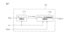
- FIG. 7 is a block diagram showing the configuration of the driver target lateral deviation setting section 61. As shown in FIG.
- the driver target lateral deviation setting section 61 (see FIG. 2) includes a yaw rate computing section 111 and a driver target lateral deviation computing section 112 .
- a yaw rate calculation unit 111 uses a vehicle model to calculate a yaw rate ⁇ d,model generated when it is assumed that the driving assistance is not functioning from the torsion bar torque T tb and the vehicle speed v x .
- the yaw rate calculator 111 may use a vehicle model to calculate the yaw rate ⁇ d,model generated with respect to the manual steering angle command value ⁇ md from the manual steering angle command value ⁇ md and the vehicle speed v x . .
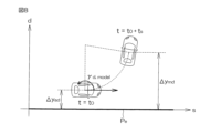
- the driver target lateral deviation calculation unit 112 calculates the lateral direction of the vehicle when it is assumed that the vehicle speed vx and the yaw rate ⁇ d ,model are constant and the vehicle makes a steady circular turn for ts seconds. is obtained as the driver's target lateral deviation ⁇ y md .
- the s-axis (horizontal axis) indicates the position in the direction (vertical direction) along the target travel route Pe of the visual information base
- the d-axis indicates the direction along the target travel route Pe .
- the position in the orthogonal direction (horizontal direction) is shown.
- the driver target lateral deviation calculator 112 calculates the driver target lateral deviation ⁇ ymd based on the following equation (15).
- Driver target lateral deviation ⁇ ymd set by driver target lateral deviation setting unit 61 is provided to host ECU 201 .
- FIG. 9 is a block diagram showing the configuration of host ECU 201 for changing the target travel route mainly using driver target lateral deviation ⁇ y md .
- the corrected route candidate generator 211 and the corrected route selector 212 constitute the "corrected travel route generator” of the present invention. Further, the driver target lateral deviation calculator 112, the corrected route candidate generator 211, the corrected route selector 212, and the target travel route generator 213 constitute the "route changer" of the present invention.
- corrected route means a route that is used to correct the target travel route based on visual information.
- a “corrected route candidate” is a candidate for a “corrected route”.
- the current lateral position y 0 , lateral velocity dy 0 /dt and lateral acceleration d 2 y 0 /dt 2 of the vehicle are obtained from the function y t (t) representing the corrected route selected by the corrected route candidate generator 211. It is calculated based on the previous value.
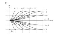
- Corrected route candidate generation unit 211 sets a plurality of completion times tf and lateral positions yrf at completion times tf as shown in the following equation (17), and for each combination thereof, the coefficient of the quintic function Determine a 0 , a 1 , a 2 , a 3 , a 4 and a 5 .
- W is a preset length in the horizontal direction (that is, a direction orthogonal to the direction along the target travel route based on visual information), and ⁇ t is a preset time.
- the corrected route selection unit 212 selects the optimum corrected route candidate from among the plurality of corrected route candidates generated by the corrected route candidate generation unit 211 as the corrected route.
- the coefficients a 0 , a 1 , a 2 , a 3 , a 4 and a 5 on the right side of equation (18) are coefficients corresponding to (i, k) in J y (i, k) on the left side. Therefore, the coefficients a 0 , a 1 , a 2 , a 3 , a 4 and a 5 obtained from equation (16) are used. As t f , t f (k) in Equation (17) corresponding to k in J y (i, k) on the left side is used.
- the correction route selection unit 212 calculates the cost J y (i, k) corresponding to the jerk, the completion time t f (k), and , the difference between the lateral position y rf (i) and the lateral deviation ⁇ y ad and the difference between the lateral position y rf (i) and the lateral deviation ⁇ y md to generate a cost function C y (i,k).
- (y rf (i) ⁇ y ad ) is the difference between the corrected route candidate and the target value for driving assistance
- (y rf (i) ⁇ y md ) is the corrected route candidate and This is the difference from the target value for manual operation.
- a correction path with small jerk, fast completion time, small (y rf (i)- ⁇ y ad ) 2 and small (y rf (i)- ⁇ y md ) 2 is preferable.
- the corrected route selection unit 212 selects the corrected route candidate with the minimum cost function C y (i, k) from among the plurality of corrected route candidates as the optimum corrected route.
- the target travel route generator 213 generates the final target travel route by correcting the visual information-based target travel route based on the corrected route selected by the corrected route selector 212 .
- the target travel route generation unit 213 adds the corrected route 302 selected by the corrected route selection unit 212 to the target travel route 301 based on the visual information, so that the final target travel route 303 is generated.
- the visual information-based target travel route 301 is represented by a coordinate system in which the longitudinal position of the vehicle is on the x-axis and the lateral position of the vehicle is on the y-axis.
- the automatic steering angle command value generation unit 214 generates an automatic steering angle command value ⁇ a for moving the vehicle along the target travel route generated by the target travel route generation unit 213 .
- an assist torque command value setting unit (not shown in FIG. 2) provided in the motor control ECU 202 uses the torsion bar torque Ttb to Set the torque command value. Then, the torque control unit 60 drives the drive circuit 41 based only on the assist torque command value.
- reaction force control gains k a and ca are set based on the driver target steering angle estimator 53, so that steering control that sufficiently reflects the driver's intention can be performed in the driving assistance mode. will be able to
- the target travel route based on visual information can be corrected (the target travel route can be changed) based on the driver target lateral deviation ⁇ ymd set by the driver target lateral deviation setting unit 61.
- the assist mode it becomes possible to perform steering control that fully reflects the driver's intention. This allows the creation of appropriate driver-system interaction conditions.
- the driver torque control gain estimator 54 calculates the spring constant kd and the viscous damping coefficient cd based on the driver target steering angle ⁇ ⁇ d , the pinion angle ⁇ p , and the torsion bar torque Ttb . Although both are estimated, only one of the spring constant kd and the viscous damping coefficient cd may be estimated. In that case, only the reaction force control gain corresponding to one of the driver torque control gains estimated by the driver torque control gain estimator 54 out of the reaction force control gains ka and ca is added to the estimated driver torque control gain. value is reflected.
- the reaction force control gain calculator 55 controls the reaction force based on the driver torque control gains ⁇ k d and ⁇ cd and the weighting coefficient ⁇ given from the host ECU 201. Gains ka and ca are calculated.
- the weighting factor ⁇ may be a fixed value preset in the motor control ECU 202 .
- the angle control section 59 (see FIG. 2) includes the feedforward control section 73, but the feedforward control section 73 may be omitted.
- the feedback control torque Tfb calculated by the feedback control section 72 becomes the basic target torque.
- the present invention can also be applied to EPSs other than column-type EPS.
- the invention can also be applied to a steer-by-wire system.
- Reference Signs List 1 electric power steering device 3 steered wheels 4 steering mechanism 18 electric motor 53 driver target steering angle estimator 54 driver torque control gain estimator 55 reaction force control gain calculator 56 Reaction force setting unit 57 Manual steering angle command value calculation unit 58 Integrated angle command value calculation unit 59 Angle control unit 60 Torque control unit 61 Driver target lateral deviation setting unit 111 Yaw rate Calculation unit 112 Driver target lateral deviation calculation unit 201 Host ECUs 201, 202 Motor control ECU 211 Correction route candidate generation unit 212 Correction route selection unit 213 Target travel route generation unit 214 Automatic Steering angle command value generator
Landscapes
- Engineering & Computer Science (AREA)
- Chemical & Material Sciences (AREA)
- Combustion & Propulsion (AREA)
- Transportation (AREA)
- Mechanical Engineering (AREA)
- Steering Control In Accordance With Driving Conditions (AREA)
Abstract
L'invention concerne un dispositif de direction qui comprend : un moteur électrique pour une commande d'angle de direction ; une unité de calcul de valeur d'instruction d'angle de direction manuelle qui calcule une valeur d'instruction d'angle de direction manuelle sur la base d'une équation de mouvement comprenant un couple de direction et un gain de commande de force de réaction ; une unité de calcul de valeur d'instruction d'angle intégrée qui calcule une valeur d'instruction d'angle intégrée par l'ajout d'une valeur d'instruction d'angle de direction manuelle à une valeur d'instruction d'angle de direction automatique pour une assistance à la conduite ; une unité de commande qui commande l'angle du moteur électrique sur la base de la valeur d'instruction d'angle intégrée ; et une unité de réglage de gain de commande de force de réaction qui règle le gain de commande de force de réaction à l'aide du couple de direction, d'informations de véhicule et d'informations routières.
Priority Applications (1)
| Application Number | Priority Date | Filing Date | Title |
|---|---|---|---|
| PCT/JP2021/041371 WO2023084646A1 (fr) | 2021-11-10 | 2021-11-10 | Dispositif de direction |
Applications Claiming Priority (1)
| Application Number | Priority Date | Filing Date | Title |
|---|---|---|---|
| PCT/JP2021/041371 WO2023084646A1 (fr) | 2021-11-10 | 2021-11-10 | Dispositif de direction |
Publications (1)
| Publication Number | Publication Date |
|---|---|
| WO2023084646A1 true WO2023084646A1 (fr) | 2023-05-19 |
Family
ID=86335273
Family Applications (1)
| Application Number | Title | Priority Date | Filing Date |
|---|---|---|---|
| PCT/JP2021/041371 WO2023084646A1 (fr) | 2021-11-10 | 2021-11-10 | Dispositif de direction |
Country Status (1)
| Country | Link |
|---|---|
| WO (1) | WO2023084646A1 (fr) |
Citations (4)
| Publication number | Priority date | Publication date | Assignee | Title |
|---|---|---|---|---|
| JP2017114324A (ja) * | 2015-12-24 | 2017-06-29 | 株式会社ジェイテクト | ハンドル操作状態判定装置 |
| JP2019194059A (ja) | 2018-04-27 | 2019-11-07 | 株式会社ジェイテクト | モータ制御装置 |
| JP2020019346A (ja) * | 2018-07-31 | 2020-02-06 | 株式会社ジェイテクト | モータ制御装置 |
| JP2021000950A (ja) * | 2019-06-24 | 2021-01-07 | 株式会社ジェイテクト | 操舵角演算装置およびそれを利用したモータ制御装置 |
-
2021
- 2021-11-10 WO PCT/JP2021/041371 patent/WO2023084646A1/fr unknown
Patent Citations (4)
| Publication number | Priority date | Publication date | Assignee | Title |
|---|---|---|---|---|
| JP2017114324A (ja) * | 2015-12-24 | 2017-06-29 | 株式会社ジェイテクト | ハンドル操作状態判定装置 |
| JP2019194059A (ja) | 2018-04-27 | 2019-11-07 | 株式会社ジェイテクト | モータ制御装置 |
| JP2020019346A (ja) * | 2018-07-31 | 2020-02-06 | 株式会社ジェイテクト | モータ制御装置 |
| JP2021000950A (ja) * | 2019-06-24 | 2021-01-07 | 株式会社ジェイテクト | 操舵角演算装置およびそれを利用したモータ制御装置 |
Similar Documents
| Publication | Publication Date | Title |
|---|---|---|
| EP3608203B1 (fr) | Appareil de commande de moteur | |
| JP7194326B2 (ja) | モータ制御装置 | |
| JP7236037B2 (ja) | 車両用操舵装置 | |
| US11685430B2 (en) | Motor control device | |
| CN110406589B (zh) | 马达控制装置 | |
| JP7129004B2 (ja) | モータ制御装置 | |
| JP2019098817A (ja) | 車両用操舵装置 | |
| EP3626580B1 (fr) | Dispositif et procédé de commande de moteur | |
| EP3744611B1 (fr) | Système de direction fonctionnant à l'énergie électrique | |
| US20220017143A1 (en) | Steering device | |
| WO2023084646A1 (fr) | Dispositif de direction | |
| WO2023079765A1 (fr) | Dispositif de commande de moteur | |
| WO2023144895A1 (fr) | Dispositif de commande de moteur | |
| WO2023286169A1 (fr) | Dispositif de commande de moteur | |
| WO2023062748A1 (fr) | Dispositif de commande de moteur | |
| WO2023127149A1 (fr) | Dispositif de commande de moteur | |
| WO2023139808A1 (fr) | Dispositif de commande de moteur | |
| WO2023079764A1 (fr) | Dispositif de commande de moteur | |
| WO2023032010A1 (fr) | Dispositif de direction | |
| WO2023100369A1 (fr) | Dispositif de commande de moteur | |
| JP2023048867A (ja) | モータ制御装置 | |
| JP2023069907A (ja) | モータ制御装置 | |
| JP2023019464A (ja) | 操舵装置 |
Legal Events
| Date | Code | Title | Description |
|---|---|---|---|
| 121 | Ep: the epo has been informed by wipo that ep was designated in this application |
Ref document number: 21964005 Country of ref document: EP Kind code of ref document: A1 |