WO2023080213A1 - 金型及び樹脂層形成方法 - Google Patents
金型及び樹脂層形成方法 Download PDFInfo
- Publication number
- WO2023080213A1 WO2023080213A1 PCT/JP2022/041238 JP2022041238W WO2023080213A1 WO 2023080213 A1 WO2023080213 A1 WO 2023080213A1 JP 2022041238 W JP2022041238 W JP 2022041238W WO 2023080213 A1 WO2023080213 A1 WO 2023080213A1
- Authority
- WO
- WIPO (PCT)
- Prior art keywords
- mold
- blade
- slot
- resin layer
- resin
- Prior art date
- Legal status (The legal status is an assumption and is not a legal conclusion. Google has not performed a legal analysis and makes no representation as to the accuracy of the status listed.)
- Ceased
Links
Images









Classifications
-
- H—ELECTRICITY
- H02—GENERATION; CONVERSION OR DISTRIBUTION OF ELECTRIC POWER
- H02K—DYNAMO-ELECTRIC MACHINES
- H02K1/00—Details of the magnetic circuit
- H02K1/04—Details of the magnetic circuit characterised by the material used for insulating the magnetic circuit or parts thereof
-
- H—ELECTRICITY
- H02—GENERATION; CONVERSION OR DISTRIBUTION OF ELECTRIC POWER
- H02K—DYNAMO-ELECTRIC MACHINES
- H02K15/00—Processes or apparatus specially adapted for manufacturing, assembling, maintaining or repairing of dynamo-electric machines
- H02K15/02—Processes or apparatus specially adapted for manufacturing, assembling, maintaining or repairing of dynamo-electric machines of stator or rotor bodies
-
- H—ELECTRICITY
- H02—GENERATION; CONVERSION OR DISTRIBUTION OF ELECTRIC POWER
- H02K—DYNAMO-ELECTRIC MACHINES
- H02K15/00—Processes or apparatus specially adapted for manufacturing, assembling, maintaining or repairing of dynamo-electric machines
- H02K15/12—Impregnating, moulding insulation, heating or drying of windings, stators, rotors or machines
Definitions
- the present invention relates to a mold and a resin layer forming method.
- Patent Document 1 discloses a stator manufacturing method including the following steps.
- a first step of obtaining a laminated body configured by laminating a plurality of core members and including an annular yoke portion and a plurality of tooth portions extending from the yoke portion in a crossing direction intersecting the yoke portion;
- a second step of inserting the core member into a slot which is a space between teeth adjacent to each other in the circumferential direction of the yoke portion among a plurality of teeth; and a third step of filling with a resin in a state to form a resin portion.
- the main body portion of the core member extends along the extending direction of the slot and is separated from the inner wall surface of the slot, and the closed portion of the core member connected to the main body portion of the slot extends. It is positioned on the slot opening side and closes the open end of the slot on the slot opening side.
- the precision of the position of the coils arranged in the slots of the stator is required for the various elements that make up the motor. Further, in the coil arrangement, it is required to improve the space occupation ratio of the coils in the slot while appropriately ensuring insulation. In the case of a configuration in which the slot is filled with a resin material, it is required to reduce the variation in thickness of the insulating layer to be formed (that is, to increase the dimensional accuracy), and a new technology is required to solve this problem. was
- the present invention has been made in view of such circumstances, and it is an object of the present invention to provide a technique for reducing variations in the thickness of an insulating layer formed in the case of a configuration in which the slots are filled with a resin material.
- a mold for molding a resin layer on the surfaces of the teeth inside the slots which are spaces between the teeth extending from the annular yoke, a blade portion housed inside the slot and having both ends disposed outside the slot; a mold piece component that supports each of the ends of the blade; a guide portion for arranging the position of the blade portion in the slot at a proper position by guiding the mold piece component; has The tooth portion has a wide region at the tip or near the tip that is widened on the slot side, A mold in which the resin layer is formed by filling a resin material in the empty space in the slot in which the blade portion is accommodated and curing the resin material.
- the guide portion has an extruding part that extrudes the mold piece part in an extending direction of the tooth part,
- the extrusion component has a screw for adjusting the amount of extrusion of the mold piece component by a screwing operation.
- the resin layer is a cured product of a resin material, The mold according to any one of [1] to [4], wherein the resin material comprises one or two thermosetting resins selected from the group consisting of epoxy resins and phenolic resins.
- the linear expansion coefficient of the blade portion is 8 ppm/° C. or more and 20 ppm/° C. or less, The mold according to [5], wherein the cured product has a linear expansion coefficient of 5 ppm/° C. or more and 25 ppm/° C. or less at a glass transition temperature or lower.
- the resin material contains a release agent,
- the release agent is one or more selected from the group consisting of carnauba wax, montan acid ester wax, diethanolamine/dimontan acid ester, tolylene diisocyanate-modified oxidized wax, higher fatty acids and metal salts thereof, and paraffin.
- the push-out part has a screw for adjusting the amount of push-out of the mold piece part by a screwing operation, The resin layer forming method according to [10], wherein the blade placement step pushes out the mold piece component by screwing the screw.
- the resin layer is a cured product of a resin material, The resin layer forming method according to any one of [9] to [12], wherein the resin material contains one or two thermosetting resins selected from the group consisting of epoxy resins and phenol resins.
- the linear expansion coefficient of the blade portion is 8 ppm/° C.
- the resin material contains a release agent, The release agent is one or more selected from the group consisting of carnauba wax, montan acid ester wax, diethanolamine/dimontan acid ester, tolylene diisocyanate-modified oxidized wax, higher fatty acids and metal salts thereof, and paraffin.
- the present invention in the case of a configuration in which the slots are filled with a resin material, it is possible to provide a technique for reducing variations in the thickness of the formed insulating layer.
- FIG. 1 is a cross-sectional view of a motor, according to an embodiment;
- FIG. 1 is a perspective view of a stator, according to an embodiment;
- FIG. 1 is a plan view of a stator, according to an embodiment;
- FIG. 4 is an enlarged view of region Y1 of FIG. 3 according to the embodiment;
- FIG. 1 is a perspective view of a stator provided with a molded portion according to an embodiment;
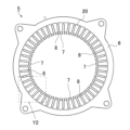
- FIG. FIG. 4 is a plan view of the stator provided with the mold portion according to the embodiment;
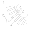
- 7 is an enlarged view of region Y2 of FIG. 6 according to the embodiment;
- FIG. 3 is a perspective view of a resin-filled mold omitting a stator housing mold and a second guide portion according to the embodiment; 18 is an enlarged view of region X3 in FIG. 17 according to the embodiment;
- FIG. FIG. 5 is a plan view showing six blade portions according to the embodiment;
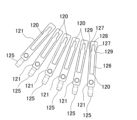
- FIG. 4 is a perspective view showing six blade portions according to an embodiment;
- FIG. 4 is a plan view illustrating the relationship between a stator and blades according to the embodiment; 22 is an enlarged view of region X4 in FIG. 21 according to the embodiment;
- FIG. 1 a manufacturing method for providing the molded portion 20 to the stator 5 and a mold 100 used for the manufacturing method will be described with reference to FIGS. 9 to 22.
- FIG. 9 a manufacturing method for providing the molded portion 20 to the stator 5 and a mold 100 used for the manufacturing method
- FIG. 1 shows a sectional view of a motor 1.
- FIG. FIG. 2 is a perspective view of the stator 5.
- FIG. 3 is a plan view of the stator 5.
- FIG. FIG. 4 is an enlarged view of region Y1 in FIG.
- FIG. 5 is a perspective view of the stator 5 with the mold portion 20 provided.
- FIG. 6 is a plan view of the stator 5 with the mold portion 20 provided.
- FIG. 7 is an enlarged view of region Y2 in FIG.
- FIG. 8 is a cross-sectional view (partially enlarged view) of the stator 5 with the molded portion 20 provided, and is a view corresponding to FIG.
- the motor 1 includes a housing 3 and a rotor 2 and a stator 5 housed inside the housing 3 .
- a shaft 2a is attached to the center of the rotor 2 as an output shaft, and is rotatably supported by two left and right bearings 4a and 4b.
- the housing 3 has a first housing cover 3a, a second housing cover 3b and a third housing cover 3c.
- the third housing cover 3c is a cylindrical housing case that accommodates the rotor 2 and the stator 5 inside. At this time, the stator 5 is attached to the inner peripheral surface of the third housing cover 3c.
- the first housing cover 3a is provided in a substantially disk shape and closes the left end opening in the axial direction of the cylindrical third housing cover 3c.
- a bearing 4a is attached to the center of the inner side surface (the left side surface in the drawing) of the first housing cover 3a so as to rotatably support the shaft 2a.
- the second housing cover 3b is provided in a substantially disc shape and closes the end opening on the right side of the drawing in the axial direction of the cylindrical third housing cover 3c.
- a bearing 4b is attached to the center of the inner side surface (the right side surface in the drawing) of the second housing cover 3b so as to rotatably support the shaft 2a.
- a plurality of permanent magnets are arranged inside the rotor 2 at regular intervals in the axial direction. At this time, the magnetic poles of adjacent permanent magnets are set to be different from each other.
- the stator 5 has a substantially cylindrical shape and is arranged and fixed so as to surround the outer periphery of the rotor 2 on the inner periphery of the housing 3 (more specifically, the third housing cover 3c). and the outer peripheral surface of the rotor 2, a minute gap (air gap) is provided.
- the stator 5 is formed by laminating a plurality of electromagnetic steel sheets, which are thin magnetic bodies.
- the stator 5 has a substantially annular yoke portion 6 and a plurality of teeth portions 7 arranged from the yoke portion 6 toward the rotor 2 side, as shown in FIGS. 3 and 4, for example.
- 48 teeth portions 7 are provided.
- Spaces called slots 8 are provided between the teeth 7 .
- a coil 9 (for example distributed winding) is accommodated in the slot 8 .
- tip protruding portions 71 having a tapered slope protruding toward the slots 8 are provided at the tip portions of the tooth portions 7 in the extending direction (rotor 2 side). As a result, the opening position of the slot 8 on the rotor 2 side is narrow.
- the tooth portions 7 are provided corresponding to the permanent magnets of the rotor 2 described above, and by sequentially exciting the coils 9, the rotor 2 rotates due to attraction and repulsion with the corresponding permanent magnets.
- a molded portion 20 made of a cured resin composition is provided in order to ensure insulation between the coil 9 and the tooth portion 7 or yoke portion 6 .
- the molded portion 20 has a tooth side surface molded portion 22, a tooth end surface molded portion 23, a yoke inner wall surface molded portion 24, and a yoke end surface molded portion 25, which are hardened resin compositions. are integrally formed as
- the tooth side mold portion 22 is provided by covering the side surface of the tooth portion 7, that is, the wall surface forming the slot 8 with a cured resin composition.
- the tooth end surface mold portions 23 are provided by covering both end surfaces of the tooth portion 7 with a resin composition.
- the yoke inner wall surface mold portion 24 is provided by covering the wall surface of the yoke portion 6 on the side of the slot 8 with a cured resin composition.
- the yoke end surface mold portions 25 are provided in the vicinity of the slots 8 and the tooth portions 7 on the upper and lower end surfaces of the yoke portion 6 so as to be annularly covered with a resin composition.
- the peripheral edge of the tooth part 7 except for the tip part of the tooth part 7 is integrally covered with the resin composition.
- the mold part 20 ensures insulation of the coil 9 accommodated in the slot 8 by thinly covering a part of the teeth part 7 and the yoke part 6 by insert molding. A resin layer forming method for providing the mold portion 20 will be described later.
- the thickness of the mold portion 20 is, for example, 0.2 mm or more and 0.5 mm or less, preferably 0.3 mm or more and 0.4 mm or less.
- the lower limit of the thickness is determined from the viewpoint of ensuring the fluidity of the resin composition in the extremely narrow portion between the mold and the tooth portion 7 with respect to the stator axial length (that is, the thickness of the stator 5) during resin molding by insert molding. Therefore, the above range is preferable.
- the upper limit in the structure in which the coil 9 is wound around the tooth portion 7 and arranged in the slot 8, from the viewpoint of the degree of freedom in the shape and winding size of the coil 9 that can be used and the performance such as magnetic flux density, it is within the above range. preferably.
- the resin composition of the mold part 20 has a glass transition temperature Tg of 150° C. or more and is made of a resin curing material with high thermal conductivity.
- the coefficient of linear expansion of the mold portion 20 at the glass transition temperature Tg or lower is 5 ppm/°C or higher and 25 ppm/°C or lower.
- the lower limit is preferably 7 ppm/°C or higher, preferably 10 ppm/°C or higher.
- the upper limit is preferably 23 ppm/°C or less, more preferably 20 ppm/°C or less.
- the resin composition preferably contains a thermosetting resin (A), a filler (B), a curing agent (C), and the like.
- thermosetting resins (A) examples include epoxy resins, cyanate resins, polyimide resins, benzoxazine resins, unsaturated polyester resins, phenol resins, melamine resins, silicone resins, bismaleimide resins, phenoxy resins, and acrylic resins. is mentioned.
- the thermosetting resin (A) one of these may be used alone, or two or more of them may be used in combination.
- the thermosetting resin (A) is preferably an epoxy resin, a phenol resin, or a phenoxy resin from the viewpoint of having high insulating properties. Epoxy resin is particularly preferred from the viewpoint of ensuring fluidity in extremely narrow portions during molding.
- epoxy resins include bisphenol A type epoxy resin, bisphenol F type epoxy resin, bisphenol E type epoxy resin, bisphenol S type epoxy resin, bisphenol M type epoxy resin (4,4′-(1,3-phenylenediiso Pridiene) bisphenol type epoxy resin), bisphenol P type epoxy resin (4,4'-(1,4-phenylenediisoprediene) bisphenol type epoxy resin), bisphenol Z type epoxy resin (4,4'-cyclohexyl bisphenol-type epoxy resins such as diene bisphenol-type epoxy resins); Novolac type epoxy resins such as novolac type epoxy resins having a hydrogen structure; biphenyl type epoxy resins; aryl alkylene type epoxy resins such as xylylene type epoxy resins and biphenyl aralkyl type epoxy resins; naphthylene ether type epoxy resins, naphthol type epoxy resins, naphthalene-type epoxy resins such as naphthalene diol-type epoxy resins, difunctional to
- epoxy resins bisphenol-type epoxy resin, novolac-type epoxy resin, biphenyl-type epoxy resin, arylalkylene-type epoxy resin, naphthalene-type epoxy resin, anthracene-type epoxy resin, It is preferably one or more selected from the group consisting of dicyclopentadiene type epoxy resins.
- phenolic resins examples include novolak-type phenolic resins such as phenol novolac resins, cresol novolac resins, and bisphenol A novolac resins, and resol-type phenolic resins. One of these may be used alone, or two or more may be used in combination. Among phenol resins, phenol novolak resins are preferred.
- the content of the thermosetting resin (A) is preferably 1% by mass or more, more preferably 5% by mass or more, relative to the total amount of the resin composition in the mold portion 20 .
- the content is preferably 30% by mass or less, more preferably 20% by mass or less, relative to the total amount of the resin composition.
- the filler (B) in the present embodiment is used from the viewpoint of improving the thermal conductivity of the mold portion 20 and obtaining strength.
- the filler (B) an inorganic filler is preferred, and a thermally conductive filler is particularly preferred. More specifically, the filler (B) includes, for example, silica, alumina, boron nitride, aluminum nitride, silicon carbide, and the like, from the viewpoint of balancing thermal conductivity and electrical insulation. These may be used individually by 1 type, or may use 2 or more types together. Among them, the filler (B) is preferably alumina or boron nitride.
- the content of the filler (B) is preferably 80% by mass or more with respect to the total amount of the resin composition.
- thermosetting resin (A) When an epoxy resin or a phenol resin is used as the thermosetting resin (A), the resin composition preferably further contains a curing agent (C).
- curing agent (C) one or more selected from curing catalysts (C-1) and phenolic curing agents (C-2) can be used.
- the curing catalyst (C-1) include organic metal salts such as zinc naphthenate, cobalt naphthenate, tin octylate, cobalt octylate, bisacetylacetonate cobalt (II), and trisacetylacetonate cobalt (III).
- tertiary amines such as triethylamine, tributylamine, 1,4-diazabicyclo[2.2.2]octane; 2-phenyl-4-methylimidazole, 2-ethyl-4-methylimidazole, 2,4-diethylimidazole , 2-phenyl-4-methyl-5-hydroxyimidazole, 2-phenyl-4,5-dihydroxymethylimidazole; triphenylphosphine, tri-p-tolylphosphine, tetraphenylphosphonium/tetraphenylborate, tri Organic phosphorus compounds such as phenylphosphine, triphenylborane, 1,2-bis-(diphenylphosphino)ethane; phenol compounds such as phenol, bisphenol A and nonylphenol; acetic acid, benzoic acid, salicylic acid, p-toluenesulfonic acid organic acids; etc., or mixtures thereof.
- the curing catalyst (C-1) one type including derivatives among these may be used alone, or two or more types including these derivatives may be used in combination.
- the content of the curing catalyst (C-1) is not particularly limited, but is preferably 0.001% by mass or more and 1% by mass or less with respect to the total amount of the resin composition.
- the phenol-based curing agent (C-2) includes novolac-type phenolic resins such as phenol novolak resin, cresol novolak resin, trisphenolmethane-type novolak resin, naphthol novolak resin, and aminotriazine novolak resin; Modified phenol resins such as cyclopentadiene-modified phenol resins; phenol aralkyl resins having a phenylene skeleton and/or biphenylene skeleton, aralkyl resins such as naphthol aralkyl resins having a phenylene skeleton and/or biphenylene skeleton; bisphenols such as bisphenol A and bisphenol F Compounds; resol-type phenolic resins, etc., may be mentioned, and these may be used singly or in combination of two or more.
- the phenolic curing agent (C-2) is preferably a novolac-type phenolic resins such as phenol novolak resin, cresol
- the content of the phenol-based curing agent (C-2) is not particularly limited, but is preferably 1% by mass or more, more preferably 5% by mass or more, relative to the total amount of the resin composition. On the other hand, the content is preferably 30% by mass or less, more preferably 15% by mass or less, relative to the total amount of the resin composition.
- the resin composition may contain a coupling agent (D).
- the coupling agent (D) can improve the wettability of the interface between the thermosetting resin (A) and the filler (B).
- the coupling agent (D) is not particularly limited, but may be selected from, for example, epoxysilane coupling agents, cationic silane coupling agents, aminosilane coupling agents, titanate coupling agents and silicone oil coupling agents. It is preferred to use one or more coupling agents that are
- the content of the coupling agent (D) is not particularly limited, but is preferably 0.05% by mass or more, more preferably 0.1% by mass or more, relative to 100% by mass of the filler (B). On the other hand, the content is preferably 3% by mass or less, more preferably 2% by mass or less, relative to 100% by mass of the filler (B).
- the resin composition may contain a phenoxy resin (E).
- a phenoxy resin (E) By including the phenoxy resin (E), the bending resistance of the mold portion 20 can be improved, the elastic modulus can be lowered, and the stress relaxation force of the mold portion 20 can be improved.
- the phenoxy resin (E) when included, the fluidity is reduced due to the increase in viscosity, and the occurrence of voids and the like can be suppressed. Further, when the mold portion 20 is used in close contact with the metal member (teeth portion 7), the adhesion between the metal and the cured resin composition can be improved.
- phenoxy resin (E) examples include phenoxy resins having a bisphenol skeleton, phenoxy resins having a naphthalene skeleton, phenoxy resins having an anthracene skeleton, and phenoxy resins having a biphenyl skeleton.
- a phenoxy resin having a structure having a plurality of these skeletons can also be used.
- the content of the phenoxy resin (E) is preferably, for example, 3% by mass or more and 10% by mass or less with respect to the total amount of the resin composition.
- the resin material of the mold portion 20 may contain a release agent.
- the release agent contains one or more selected from the group consisting of carnauba wax, montan acid ester wax, diethanolamine/dimontan acid ester, tolylene diisocyanate-modified oxidized wax, higher fatty acids and metal salts thereof, and paraffin. .
- the content of the release agent in the resin composition is preferably 0.1% by mass or more and 5% by mass or less with respect to the entire resin composition from the viewpoint of obtaining preferable releasability.
- the lower limit is preferably 0.2% by mass or more, more preferably 0.3% by mass or more.
- the upper limit is preferably 3% by mass or less, more preferably 1% by mass or less.
- the resin composition of the mold portion 20 may additionally contain an antioxidant, a leveling agent, and the like within a range that does not impair the effects of the present invention.
- a mold 100 used to manufacture the stator 5 having the mold portion 20 described above and a resin layer forming method for forming the mold portion 20 on the stator 5 using the mold 100 will be described.
- the blade portion 120 which is a mold component, is placed in the slot 8, and the space between the blade portion 120 and the slot 8 is filled with A resin material is filled and hardened to form the molded portion 20 .
- the blade portion 120 (the pressing portion 127 of the convex portion 129) is pressed against the tapered shape of the tip of the tooth portion 7 (that is, the tip projecting portion 71). This eliminates the influence of the dimensional tolerance of the stator 5 and prevents the resin material from leaking to the inner diameter side (rotor 2 side).
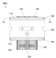
- FIG. 9 is a front view of the mold 100.
- FIG. FIG. 10 is a cross-sectional view of the mold 100.
- the mold 100 has a lower mold 100a, an upper mold 100b, and a resin-filled mold 100c arranged between the lower mold 100a and the upper mold 100b.
- the mold 100 can use a general mold steel material, for example, SKD-11 (JIS standard). These are assembled in a predetermined arrangement by means of positioning members (pins, blocks, etc.).
- the lower mold 100 a has a base mold 101 , a first lower mold 102 , a second lower mold 103 and a third lower mold 115 .
- a cylindrical first lower mold 102 is placed on a base mold 101 that is a rectangular plate member, and a substantially columnar third lower mold 115 is arranged at the center of the first lower mold 102 .
- a disk-shaped second lower mold 103 is placed on the first lower mold 102 and the second lower mold 103 so as to cover them.
- a space is formed to accommodate the lower end portions of the plurality of blade portions 120 protruding downward in a resin-filled mold 100c, which will be described later.
- a resin-filled mold 100c accommodating the stator 5 is placed on the lower mold 100a, that is, on the second lower mold 103. As shown in FIG.
- the upper mold 100 b has a first upper mold 108 , a second upper mold 107 and a third upper mold 109 .
- a disk-shaped second upper mold 107 is placed on the resin-filled mold 100c placed on the lower mold 100a.
- An upper mold 108 is attached.
- FIG. 11 is a front view of the resin-filled mold 100c. 12 is a sectional view of the stator 5.
- FIG. FIG. 13 is a perspective view of the resin-filled mold 100c.
- FIG. 14 is an enlarged view of region X1 in FIG.
- FIG. 15 is a cross-sectional view of the second guide portion 106.
- FIG. 16 is an enlarged view of region X2 in FIG.
- FIG. 17 is a perspective view of the resin-filled mold 100c with the stator housing mold 105 and the second guide portion 106 omitted.
- FIG. 18 is an enlarged view of region X3 in FIG.
- FIG. 11 is a plan view showing six blade portions 120.
- FIG. FIG. 20 is a perspective view showing six blade portions 120.
- FIG. FIG. 19 is a plan view showing six blade portions 120.
- FIG. FIG. 21 is a plan view for explaining the relationship between the stator 5 and the blade portion 120.
- FIG. FIG. 22 is an enlarged view of
- the resin-filled mold 100c has a stator housing mold 105, a first guide portion 104, a second guide portion 106, a central mold 112, and a blade portion 120. It is arranged and fixed between 100a and upper die 100b.
- the stator housing mold 105 has a substantially cylindrical shape and houses the stator 5 therein. At this time, the stator 5 is arranged at a predetermined position by the guide pin 111 .
- a cylindrical central mold 112 is arranged in the central opening of the stator 5 (the region in which the rotor 2 is arranged).
- a side surface of the central mold 112 is provided with a groove portion 119 for accommodating a blade tip portion 128 of the blade portion 120 to be described later.
- a first guide portion 104 and a second guide portion 106 are arranged and fixed at the upper and lower opening ends of the stator housing mold 105 housing the stator 5 .
- the first guide portion 104 and the second guide portion 106 are annular plate-like members having the same shape, and guide the blade portion 120 in the slot 8 so that it is positioned at a proper position. A guide method will be described later.
- the second guide portion 106 will be described below, and the description of the first guide portion 104 will be omitted.
- the second guide part 106 is an annular plate-like member having a fitting hole 118 in the central part thereof, into which a protrusion projecting from the end of the central mold 112 is fitted.
- the shape of the fitting hole 118 is a shape corresponding to the central mold 112, and is formed in a substantially rectangular shape here.
- the second guide portion 106 has a plurality of guide portion arrangement holes 113 penetrating in the thickness direction. These guide portion arrangement holes 113 are arranged at predetermined intervals in the circumferential direction. The guide portion arrangement holes 113 are provided at 48 locations facing the slots 8 of the stator 5 . That is, when the second guide portion 106 is attached to the stator housing mold 105, the slot 8 and the guide portion arrangement hole 113 are aligned.
- the guide portion arrangement hole 113 is formed in a rectangular shape larger than the slot 8, and can accommodate a mold piece component 121 attached to the blade portion 120, which will be described later. possible shape.
- a guide hole 114 communicating with the guide portion arrangement hole 113 is provided on the outer surface of the second guide portion 106 .
- An extruding part for extruding the mold piece part 121 in the extending direction of the tooth portion 7 (that is, in the radial direction) is attached to the guide hole 114 .
- the blade part 120 to which the mold piece part 121 is attached moves in the extending direction of the teeth part 7 .
- the tooth portion 7 side tip portion of the blade portion 120 is pressed against the wide area (tip projection portion 71).
- a guide screw 125 that can adjust the amount of pushing out the die piece part 121 by a screwing operation is used as the extruding part.
- a guide screw 125 is used that can adjust the amount by which the mold piece component 122 is pushed out by a screwing operation.
- the blade part 120 is a mold member formed in a long plate shape (blade shape).
- the blade part 120 has a shape in which both ends in the longitudinal direction are arranged outside the slot 8 when the blade part 120 is housed inside the slot 8 .
- Mold pieces 121 and 122 are attached to both ends of the blade portion 120 (portions protruding from the slot 8).
- the blade portion 120 has a substantially rectangular shape when viewed from above (or in cross section), and slightly protrudes from the blade portion main body 126 in both lateral directions (toward the teeth portion 7 when accommodated in the slot 8). It has a convex portion 129 and a blade tip portion 128 on the front side of the convex portion 129 in the extending direction.
- the blade portion main body 126 is provided slightly smaller than the slot 8 in cross-sectional view. That is, in a state where the blade portion 120 is accommodated in the slot 8, a small U-shaped space (hereinafter referred to as "surplus space”) is formed. A mold portion 20 is formed in this empty space.
- the protruding portion 129 abuts on the tooth portion side surface 72 at the protruding tip.
- a tapered slope (hereinafter referred to as “pressing portion 127 ”) formed on the tip end side of the convex portion 129 abuts on the slope of the tip projecting portion 71 of the tooth portion 7 .
- the die piece parts 121 and 122 provided at both ends of the blade portion 120 are arranged as described above.
- the first and second guide portions 104 and 106 are used to push in the guide screw 125 .
- the blade portion 120 is accurately arranged at an appropriate position within the slot 8 .
- the stator 5 can be obtained with less variation in the thickness of the insulating layer.
- At least the surface of the blade portion main body 126 of the blade portion 120 is a mirror surface (for example, approximately No. 1000). As a result, when the blade portion 120 is pulled out from the slot 8, it is possible to prevent the mold portion 20 from being affected by distortion or the like.
- the coefficient of linear expansion of the blade portion 120 is 8 ppm/°C or more and 20 ppm/°C.
- the lower limit is preferably 10 ppm/°C or higher, more preferably 12 ppm/°C or higher.
- the upper limit is preferably 18 ppm/°C or less, more preferably 15 ppm/°C or less. That is, the blade portion 120 is made of mold steel having a coefficient of linear expansion within the range described above. At that time, it is preferable that there is no difference from the linear expansion coefficient of the resin composition of the mold portion 20 described above.
- Resin layer forming method A procedure (resin layer forming method) for forming the mold portion 20 on the stator 5 using the mold 100 having the above configuration will be described.
- the resin layer forming method has a blade accommodation step (S10), a blade placement step (S12), and a resin filling step (S14).
- the blade portion 120 is accommodated in the slot 8, and mold pieces 121 and 122 are attached to both ends of the blade portion 120. At this time, the mold piece parts 121 and 122 are attached to the portions protruding outside from the ends of the slot 8 .
- the mold piece parts 121 and 122 are guided by guides (first and second guides 104 and 106 and guide screws 125) to position the blade 120 in the slot 8. Place it in the proper position. That is, by screwing in the guide screw 125, which is an extruded part, the die piece parts 121 and 122 are pushed out toward the center, and the blade part 120 (that is, the pressing part 127) is pushed into the wide area (tip protruding part 71) of the tooth part 7. guess.
- the resin material is filled into the empty space in the slot 8 while the blade portion 120 is arranged in the slot 8 at an appropriate position.
- the mold part 20 is formed by this.
- the resin material filled in the spare space in the slot 8 will not flow into the center side opening of the slot 8. does not leak from
Landscapes
- Engineering & Computer Science (AREA)
- Power Engineering (AREA)
- Manufacturing & Machinery (AREA)
- Iron Core Of Rotating Electric Machines (AREA)
- Manufacture Of Motors, Generators (AREA)
- Moulds For Moulding Plastics Or The Like (AREA)
Priority Applications (1)
| Application Number | Priority Date | Filing Date | Title |
|---|---|---|---|
| JP2023525511A JP7375984B2 (ja) | 2021-11-08 | 2022-11-04 | 金型及び樹脂層形成方法 |
Applications Claiming Priority (2)
| Application Number | Priority Date | Filing Date | Title |
|---|---|---|---|
| JP2021181662 | 2021-11-08 | ||
| JP2021-181662 | 2021-11-08 |
Publications (1)
| Publication Number | Publication Date |
|---|---|
| WO2023080213A1 true WO2023080213A1 (ja) | 2023-05-11 |
Family
ID=86241501
Family Applications (1)
| Application Number | Title | Priority Date | Filing Date |
|---|---|---|---|
| PCT/JP2022/041238 Ceased WO2023080213A1 (ja) | 2021-11-08 | 2022-11-04 | 金型及び樹脂層形成方法 |
Country Status (2)
| Country | Link |
|---|---|
| JP (1) | JP7375984B2 (https=) |
| WO (1) | WO2023080213A1 (https=) |
Families Citing this family (1)
| Publication number | Priority date | Publication date | Assignee | Title |
|---|---|---|---|---|
| WO2025115769A1 (ja) * | 2023-12-01 | 2025-06-05 | 住友ベークライト株式会社 | 熱硬化性樹脂組成物およびステータの製造方法 |
Citations (6)
| Publication number | Priority date | Publication date | Assignee | Title |
|---|---|---|---|---|
| JPH09193167A (ja) * | 1996-01-22 | 1997-07-29 | Fujikura Ltd | 電気・電力用エポキシ硬化物の製造方法 |
| JP2000125524A (ja) * | 1998-10-15 | 2000-04-28 | Mitsubishi Electric Corp | 固定子鉄心の製造方法および固定子鉄心の絶縁層被覆用モールド金型、並びに固定子鉄心 |
| WO2003028188A1 (fr) * | 2001-09-21 | 2003-04-03 | Aisin Aw Co., Ltd. | Noyau dote d'un element d'isolation et procede de production dudit noyau |
| JP2017163703A (ja) * | 2016-03-09 | 2017-09-14 | 株式会社三井ハイテック | 積層鉄心の製造方法 |
| JP2018133983A (ja) * | 2017-02-13 | 2018-08-23 | 株式会社三井ハイテック | 固定子積層鉄心の製造方法及び固定子積層鉄心 |
| JP2019093637A (ja) * | 2017-11-22 | 2019-06-20 | 株式会社三井ハイテック | 鉄心製品の製造方法 |
-
2022
- 2022-11-04 JP JP2023525511A patent/JP7375984B2/ja active Active
- 2022-11-04 WO PCT/JP2022/041238 patent/WO2023080213A1/ja not_active Ceased
Patent Citations (6)
| Publication number | Priority date | Publication date | Assignee | Title |
|---|---|---|---|---|
| JPH09193167A (ja) * | 1996-01-22 | 1997-07-29 | Fujikura Ltd | 電気・電力用エポキシ硬化物の製造方法 |
| JP2000125524A (ja) * | 1998-10-15 | 2000-04-28 | Mitsubishi Electric Corp | 固定子鉄心の製造方法および固定子鉄心の絶縁層被覆用モールド金型、並びに固定子鉄心 |
| WO2003028188A1 (fr) * | 2001-09-21 | 2003-04-03 | Aisin Aw Co., Ltd. | Noyau dote d'un element d'isolation et procede de production dudit noyau |
| JP2017163703A (ja) * | 2016-03-09 | 2017-09-14 | 株式会社三井ハイテック | 積層鉄心の製造方法 |
| JP2018133983A (ja) * | 2017-02-13 | 2018-08-23 | 株式会社三井ハイテック | 固定子積層鉄心の製造方法及び固定子積層鉄心 |
| JP2019093637A (ja) * | 2017-11-22 | 2019-06-20 | 株式会社三井ハイテック | 鉄心製品の製造方法 |
Also Published As
| Publication number | Publication date |
|---|---|
| JP7375984B2 (ja) | 2023-11-08 |
| JPWO2023080213A1 (https=) | 2023-05-11 |
Similar Documents
| Publication | Publication Date | Title |
|---|---|---|
| JP7594011B2 (ja) | ステータ、回転電機およびステータの製造方法 | |
| JP6373854B2 (ja) | ステータ又はロータ | |
| JP5916591B2 (ja) | アキシャルギャップモータ | |
| JP7375984B2 (ja) | 金型及び樹脂層形成方法 | |
| CN110676955B (zh) | 带有与定子凹槽间隔开的电导体的电动马达 | |
| KR20150077443A (ko) | 전기 모터 또는 발전기를 위한 치부 | |
| CN101258661A (zh) | 定子铁芯、使用定子铁芯的电动机及定子铁芯的制造方法 | |
| CN101124710A (zh) | 旋转电机的转子 | |
| JP2022092163A (ja) | 電動機用ステータおよび電動機 | |
| JP2024123482A (ja) | ステータの製造方法 | |
| JP7311072B1 (ja) | ステータの製造方法、ステータ、ティース及びヨーク | |
| JP7608804B2 (ja) | 構造体 | |
| US20230340291A1 (en) | Coating composition for electrical steel sheet, electrical steel sheet, laminated core and rotary electric machine | |
| JP2010178520A (ja) | ステータおよびモータ | |
| JP2010200492A (ja) | インシュレータ、ステータおよびモータ | |
| WO2025197744A1 (ja) | ステータの製造方法 | |
| EP4675900A1 (en) | Bus-bar substrate, bus-bar substrate device, stator, and stator manufacturing method | |
| JP2022149379A (ja) | ステータおよび回転電機 | |
| JP2007215334A (ja) | 電動機用固定子及び電動機 | |
| JP7754372B2 (ja) | 構造体、インバータモジュール、モータ、および構造体の製造方法 | |
| JP2024123480A (ja) | バスバー基板、バスバー基板装置およびステータ | |
| JP2025019635A (ja) | ステータの製造方法、ステータおよび金型 | |
| JP2025119722A (ja) | ロータ、回転電機、およびロータの製造方法 | |
| WO2025115769A1 (ja) | 熱硬化性樹脂組成物およびステータの製造方法 | |
| KR20250061203A (ko) | 모터용 회전자 및 그 제조 방법 |
Legal Events
| Date | Code | Title | Description |
|---|---|---|---|
| WWE | Wipo information: entry into national phase |
Ref document number: 2023525511 Country of ref document: JP |
|
| 121 | Ep: the epo has been informed by wipo that ep was designated in this application |
Ref document number: 22890033 Country of ref document: EP Kind code of ref document: A1 |
|
| 122 | Ep: pct application non-entry in european phase |
Ref document number: 22890033 Country of ref document: EP Kind code of ref document: A1 |