WO2023080044A1 - Imaging element and ranging device - Google Patents
Imaging element and ranging device Download PDFInfo
- Publication number
- WO2023080044A1 WO2023080044A1 PCT/JP2022/040046 JP2022040046W WO2023080044A1 WO 2023080044 A1 WO2023080044 A1 WO 2023080044A1 JP 2022040046 W JP2022040046 W JP 2022040046W WO 2023080044 A1 WO2023080044 A1 WO 2023080044A1
- Authority
- WO
- WIPO (PCT)
- Prior art keywords
- charge
- light receiving
- light
- signal
- time
- Prior art date
Links
- 238000003384 imaging method Methods 0.000 title claims abstract description 16
- 238000003860 storage Methods 0.000 claims description 17
- 238000010791 quenching Methods 0.000 claims description 5
- 238000006243 chemical reaction Methods 0.000 claims description 4
- 230000003247 decreasing effect Effects 0.000 claims description 2
- 238000007599 discharging Methods 0.000 claims 3
- 239000003990 capacitor Substances 0.000 description 49
- 238000010586 diagram Methods 0.000 description 17
- 238000005259 measurement Methods 0.000 description 12
- 238000004364 calculation method Methods 0.000 description 3
- 230000015556 catabolic process Effects 0.000 description 3
- 230000007423 decrease Effects 0.000 description 3
- 238000005516 engineering process Methods 0.000 description 3
- 238000009825 accumulation Methods 0.000 description 2
- 230000003111 delayed effect Effects 0.000 description 2
- 238000001514 detection method Methods 0.000 description 2
- 238000007667 floating Methods 0.000 description 2
- 238000000034 method Methods 0.000 description 2
- 230000000171 quenching effect Effects 0.000 description 2
- 238000011084 recovery Methods 0.000 description 2
- 238000007792 addition Methods 0.000 description 1
- 230000004888 barrier function Effects 0.000 description 1
- 230000008859 change Effects 0.000 description 1
- 230000006835 compression Effects 0.000 description 1
- 238000007906 compression Methods 0.000 description 1
- 238000009792 diffusion process Methods 0.000 description 1
- 238000012886 linear function Methods 0.000 description 1
- 238000004519 manufacturing process Methods 0.000 description 1
- 238000012986 modification Methods 0.000 description 1
- 230000004048 modification Effects 0.000 description 1
- 230000003071 parasitic effect Effects 0.000 description 1
- 229920006395 saturated elastomer Polymers 0.000 description 1
- 230000001360 synchronised effect Effects 0.000 description 1
Images


Classifications
-
- G—PHYSICS
- G01—MEASURING; TESTING
- G01S—RADIO DIRECTION-FINDING; RADIO NAVIGATION; DETERMINING DISTANCE OR VELOCITY BY USE OF RADIO WAVES; LOCATING OR PRESENCE-DETECTING BY USE OF THE REFLECTION OR RERADIATION OF RADIO WAVES; ANALOGOUS ARRANGEMENTS USING OTHER WAVES
- G01S17/00—Systems using the reflection or reradiation of electromagnetic waves other than radio waves, e.g. lidar systems
- G01S17/88—Lidar systems specially adapted for specific applications
- G01S17/89—Lidar systems specially adapted for specific applications for mapping or imaging
- G01S17/894—3D imaging with simultaneous measurement of time-of-flight at a 2D array of receiver pixels, e.g. time-of-flight cameras or flash lidar
-
- G—PHYSICS
- G01—MEASURING; TESTING
- G01S—RADIO DIRECTION-FINDING; RADIO NAVIGATION; DETERMINING DISTANCE OR VELOCITY BY USE OF RADIO WAVES; LOCATING OR PRESENCE-DETECTING BY USE OF THE REFLECTION OR RERADIATION OF RADIO WAVES; ANALOGOUS ARRANGEMENTS USING OTHER WAVES
- G01S7/00—Details of systems according to groups G01S13/00, G01S15/00, G01S17/00
- G01S7/48—Details of systems according to groups G01S13/00, G01S15/00, G01S17/00 of systems according to group G01S17/00
- G01S7/483—Details of pulse systems
- G01S7/486—Receivers
- G01S7/4861—Circuits for detection, sampling, integration or read-out
- G01S7/4863—Detector arrays, e.g. charge-transfer gates
-
- H—ELECTRICITY
- H04—ELECTRIC COMMUNICATION TECHNIQUE
- H04N—PICTORIAL COMMUNICATION, e.g. TELEVISION
- H04N25/00—Circuitry of solid-state image sensors [SSIS]; Control thereof
- H04N25/70—SSIS architectures; Circuits associated therewith
- H04N25/76—Addressed sensors, e.g. MOS or CMOS sensors
- H04N25/77—Pixel circuitry, e.g. memories, A/D converters, pixel amplifiers, shared circuits or shared components
Definitions
- the present disclosure relates to an imaging device and a distance measuring device.
- distance measuring devices and distance measuring systems that measure the distance to the subject using a light receiving array equipped with multiple single photon avalanche diodes (SPAD).
- SPAD single photon avalanche diodes
- the distance measuring device of Patent Document 1 includes a control section and a distance calculation section.
- the control unit determines a distance range for performing distance measurement, and divides a time range corresponding to this distance range into a plurality of intervals.
- the control unit controls the distance measuring device so that the pulsed light is emitted and the light receiving unit is exposed for each time range.
- the distance calculation section calculates the distance to the subject according to the exposure result of the light receiving section.
- the distance measurement accuracy at this time is determined by the pulse width of the pulsed light emitted by the light emitting unit.
- a distance measuring device such as that disclosed in Patent Document 1 may use a light receiving unit that performs photon counting, in which a plurality of pulsed light beams are emitted during one exposure period and the light beams (photons) reflected by the subject are counted. be.
- a light receiving portion a capacitor is provided in each pixel, and the charge amount corresponding to the number of received photons is accumulated in the capacitor.
- the nonlinear compression rate of the photon counting value and the corresponding real physical quantity (charge amount) is insufficient, so it is difficult to perform photo counting with a high dynamic range in an environment with strong background light.
- An object of the present disclosure is to provide an imaging device and a distance measuring device that enable photo counting in a high dynamic range.
- an imaging device includes a plurality of pixels, each pixel includes a light receiving device, a first storage device, and each pixel provided therein, and a charge discharge device that discharges charges to the first storage element for a certain period of time when the light receiving element detects light irradiated by a light source and reflected by an object.
- FIG. 2 is a block diagram showing the configuration of a pixel according to the first embodiment
- FIG. 4A and 4B are diagrams for explaining the principle of operation of the charge emission device according to the first embodiment
- FIG. 2 is a block diagram showing the configuration of a light receiving sensor according to the first embodiment
- FIG. 4 is a diagram for explaining a circuit example configured in a pixel according to the first embodiment
- FIG. 4 is a timing chart regarding distance measurement operation of pixels during one frame period according to the first embodiment
- It is a block diagram which shows an example of the whole structure of the distance measuring device which concerns on 2nd Embodiment.
- FIG. 4A and 4B are diagrams for explaining the principle of operation of the charge emission device according to the first embodiment
- FIG. 2 is a block diagram showing the configuration of a light receiving sensor according to the first embodiment
- FIG. 4
- FIG. 10 is a diagram for explaining the principle of distance measurement by the distance measuring device according to the second embodiment
- FIG. 11 is a diagram for explaining a method of generating a subrange image according to the second embodiment
- FIG. 11 is a timing chart regarding ranging operation of pixels during one frame period according to the second embodiment
- FIG. 1 is a block diagram showing the configuration of a pixel according to the first embodiment. Pixels 30 shown in FIG. 1 are arranged in a light receiving sensor 2 (imaging device) of a distance measuring device, which will be described later.
- the pixel 30 includes a light receiving element 31, a reset transistor 32, a photocount control circuit 33, a charge discharge device 34, a source follower transistor 35, a selection transistor 36, and a first capacitor 37 ( a first storage element). Note that the reset timing control device 38 and the charge supply device 39 are arranged outside the pixel 30 .
- the light receiving element 31 is, for example, a photodiode (PD) such as a SPAD or an avalanche photodiode (APD).
- PD photodiode
- SPAD SPAD
- APD avalanche photodiode
- the reset transistor 32 has a source (or drain) connected to the output terminal of the reset timing control device 38, a drain (or source) connected to the cathode terminal of the light receiving element 31 and the input terminal of the photocount control circuit 33, and a gate Receives reset signal V RST .
- the reset timing control device 38 supplies a voltage for the reset transistor 32 to reset the light receiving element 31 and the like to the reset transistor 32 .
- the input terminal of the charge discharge device 34 is connected to the output terminal of the photocount control circuit 33 .
- the photocount control circuit 33 performs a photocounting operation according to the output from the cathode terminal of the light receiving element 31, and outputs the result from the output terminal. For example, the photocount control circuit 33 outputs a pulse voltage to the charge discharge device 34 when the light receiving element 31 detects light (photons).
- the charge discharge device 34 receives signals from the photocount control circuit 33 and the charge supply device 39 and outputs charges to the floating diffusion FD. For example, the charge discharge device 34 outputs a predetermined charge to the FD when the photocount control circuit 33 outputs a pulse voltage.
- the charge supply device 39 supplies charges for output to the charge discharge device 34 .
- the source follower transistor 35 receives the pixel power supply bias signal Vc at its source (or drain), has its drain (or source) connected to the source (or drain) of the selection transistor 36, and has its gate connected to FD.
- the select transistor 36 has a drain (or source) connected to the output line 26 and a gate receiving a select signal V SEL .
- the first capacitor 37 has one end connected to the FD and the other end connected to the ground voltage (earth). The first capacitor 37 accumulates the charge output from the charge discharge device 34 to the FD.
- the source follower transistor 35 outputs a pixel signal corresponding to the charge accumulated in the first capacitor 37 to the output line 26 when the selection transistor 36 is turned on.
- C F be the capacity of the FD
- C M be the capacity of the storage capacitor
- r M C M /(C F + C M ) be the ratio of the two in Patent Document 1
- the FD be saturated charge when each photon is detected.
- the amount Q 0 is transferred
- the amount of charge additionally stored in the storage capacitor is r M i Q 0 when the i-th photon is detected. Therefore, the total charge accumulated in the storage capacitor when m photons are detected is
- r M 0.9 is the limit value, and the maximum count value of the number of photons that can be accumulated in the pixel remains at about 15.
- the amount of charge output from the charge emission device 34 to the FD is small.
- the minimum value of the amount of charge output from the charge discharge device 34 to the FD is defined by kTC noise generated when the first capacitor 37 is charged and discharged. It becomes about 63 electrons.
- the amount of charge required to output a pixel signal is approximately 125 electrons.
- the charge discharge device 34 needs (1) a minute current (typically 10 nA) and (2) an extremely short time (typically 2 ns). ) is required.
- FIG. 2 is a diagram for explaining the principle of operation of the charge emission device according to the first embodiment.
- the charge discharge device 34 is, for example, a MOSFET having a source (or drain) connected to a capacitor (here, a second capacitor 343) and a drain (or source) connected to the first capacitor 37.
- FIG. By charging the second capacitor 343 with a certain amount of charge and operating the MOSFET in the subthreshold region, the charge discharge device 34 outputs a minute current to the drain (first capacitor 37). For example, when a predetermined bias voltage is applied to the gate of the MOSFET each time the light receiving element 31 detects one photon, the charge discharge device 34 discharges charges from the source to the drain for a certain period of time.
- FIG. 3 is a schematic diagram of a potential diagram of the charge emission device 34 according to the first embodiment.
- n and k are parameters representing the number of electrons emitted from the second capacitor 343 from the initial state.
- Sk the state of the MOSFET when k electrons are emitted from the second capacitor 343 and a predetermined bias voltage is applied to the gate.
- Sk the state of the MOSFET when k electrons are emitted from the second capacitor 343 and a predetermined bias voltage is applied to the gate.
- Sk the state of the MOSFET when k electrons are emitted from the second capacitor 343 and a predetermined bias voltage is applied to the gate.
- ⁇ k be the average discharge rate of charges from the second capacitor 343 when the MOSFET is in state S k .
- ⁇ 0 be the average emission rate in the initial state S 0 in which no charge is emitted from the second capacitor 343 .
- a predetermined bias voltage is applied to the gate of the charge discharge device 34 for a certain period of time ⁇ T.
- the period during which charges are emitted from the source to the drain of the charge emission device 34 while counting m photons is m ⁇ T from the operating conditions. Therefore, by taking the sum of tk (1) to tk(m) , the function of the charge emission number of the charge emission device 34 is
- the charge emission device 34 has a logarithmically compressed charge emission amount k(m) with respect to the photon count m. Therefore, the increase of k(m) is suppressed for the value of m, and high m values can be counted.
- FIG. 3 shows the relationship between the photon count value and the charge emission amount of the charge emission device according to the first embodiment.
- the amount of charge k(m)-k(m-1) applied is displayed as a function of the count value m.
- FIG. 4 is a block diagram showing the configuration of the light receiving sensor according to the first embodiment.
- the light receiving sensor 2 includes a bias generation circuit 20, a pixel array 21, a readout circuit 22, a horizontal output circuit 23, a vertical drive circuit 24, and a sensor timing generator 25.
- FIG. 20 shows that the light receiving sensor 2 includes a bias generation circuit 20, a pixel array 21, a readout circuit 22, a horizontal output circuit 23, a vertical drive circuit 24, and a sensor timing generator 25.
- a bias generation circuit 20 supplies a bias signal (details are omitted) necessary for driving the light receiving sensor 2 .
- the bias signal may be configured to be supplied from the outside.
- the pixel array 21 includes a plurality of pixels 30 arranged in an array.
- a plurality of pixels 30 are connected to a selection signal V SEL , a reset signal V RST , a PD bias control signal V D , a charge charge signal V I , a charge control signal V R, a pixel power bias signal Vc and an inverter bias signal V INV for each row. is supplied.
- Each pixel 30 responds to the supplied selection signal V SEL , reset signal V RST , PD bias control signal V D , charge charge signal V I , charge control signal V R , pixel power bias signal Vc and inverter bias signal V INV . Then, a pixel signal indicating the detection result is output to the output line 26 .
- the readout circuit 22 includes multiple column circuits 221 .
- a column circuit 221 includes an amplifier and an AD converter, and is provided for each column of pixels 30 .
- the readout circuit 22 reads the signal output from each pixel 30 via the output line 26 by the column circuit 221 .
- the horizontal output circuit 23 sequentially outputs the signals output from the readout circuit 22 as output signals.
- the vertical drive circuit 24 generates a selection signal V SEL , a reset signal V RST , a PD bias control signal V D , a charge charge signal V I , a charge control signal V R, a pixel power bias signal Vc and an inverter bias signal V INV , Output to each pixel 30 at a predetermined timing.
- the sensor timing generator 25 outputs drive timing signals indicating drive timings of the horizontal output circuit 23 and the vertical drive circuit 24 .
- FIG. 5A is a diagram showing a circuit example configured in a pixel according to the first embodiment.
- FIG. 5(a) is an example of a circuit configured in the pixel of FIG.
- the pixel 30 includes a light receiving element 31, a reset transistor 32, an inverting amplifier transistor 331, a load transistor 332, a charging transistor 341, a charge emission source transistor 342, and a second capacitor 343 ( , a source follower transistor 35 , a selection transistor 36 , and a first capacitor 37 .
- the photocount control circuit 33 in FIG. 1 is composed of an inverting amplifier transistor 331 and a depletion type transistor 332 .
- the charge discharge device 34 of FIG. 1 is composed of a charging transistor 341 , a charge discharge source transistor 342 and a second capacitor 343 .
- a predetermined voltage is input to the anode terminal of the light receiving element 31 .
- the reset transistor 32 is turned on, and the voltage between the drain of the reset transistor 32 (PD bias control signal V D ) and the anode terminal of the light receiving element 31 is kept above a predetermined breakdown voltage.
- the drain of the reset transistor 32 (PD bias control signal V D ) is set to 0 V and functions as a source, and the voltage between the cathode terminal and the anode terminal of the light receiving element 31 is below the breakdown voltage. set.
- the inverting amplifier transistor 331 has a source (or drain) connected to the drain (or source) of the load transistor 332 and the gate of the charge emission source transistor 342 , a drain connected to a ground voltage (earth), and a gate connected to the reset transistor 32 . It is connected to the drain (or source) and the cathode terminal of the light receiving element 31 .
- Load transistor 332 receives inverter bias signal V INV at its source (or drain).
- the inverting amplifier transistor 331 constitutes an inverting amplifier (inverter) by using the depletion type transistor 332 as a load.
- the charging transistor 341 receives the charge charging signal VI at its source (or drain), the charge control signal V R at its gate, and the source (or drain) of the charge discharge source transistor 342 and the second V at its drain (or source). One end of the capacitor 343 is connected.
- the charge emission source transistor 342 has a drain (or source) connected to an FD (not shown in the drawing) and a first capacitor 37 (CM) connected in parallel with this. A ground voltage is connected to the other end of the second capacitor 343 .
- the charging transistor 341 charges the second capacitor 343 to a predetermined voltage according to the charging control signal VR .
- the voltage of the cathode terminal of the light receiving element 31 drops instantaneously.
- the voltage at the cathode terminal of the light receiving element 31 is the time constant R P ⁇ C S (C S is the capacitance of the light receiving element 31 and wiring, and R P is the total resistance of the channel and wiring of the reset transistor 32 (quenching resistance). equivalent))
- the voltage supplied from the source of the reset transistor 32 (PD bias control signal V D ) is automatically restored (see FIG. 5B). That is, the light receiving element 31 performs self-quenching and self-recovery operations.
- the inverter By inputting the voltage of the anode terminal of the light-receiving element 31 to the inverter (photocount control circuit 33: inverting amplifier transistor 331 and depletion type transistor 332), the inverter has a certain width of ⁇ T determined by the threshold value of the inverter. A square wave signal is generated (see FIG. 5(c)). Specifically, by inputting the voltage of the anode terminal of the light receiving element 31 to the gate of the inverting amplifier transistor 331 , the rectangular wave signal is output to the gate of the charge emission source transistor 342 . That is, the constant time ⁇ T is given by using a as a parameter
- a circuit that generates a rectangular wave signal that has a high voltage for a certain period of time ⁇ T is configured by the capacitor C S , the resistor R P and the inverter.
- the charge emission source transistor 342 is turned on for a certain period of time ⁇ T. That is, when the light receiving element 31 receives photons, the charge emission source transistor 342 emits electrons from the second capacitor 343 charged with a predetermined voltage to the first capacitor 37 for a certain time ⁇ T. .
- the charge emission rate of the charge emission source transistor 342 is brought to the state represented by the formula (1).
- the pixel 30 can obtain the charge storage amount k(m) according to the formula (5) with respect to the photon count m, so that the photon count value can obtain a high value up to about 30.
- a voltage corresponding to this charge accumulation amount is read from the pixel 30 by the source follower transistor 35 and the selection transistor 36, amplified by the column amplifier circuit 40 (inverse logarithmic conversion circuit), and output.
- the column amplifier circuit 40 includes an anti-logarithmic conversion circuit, which outputs a voltage corresponding to the amount of charge represented by Equation (5) as a linear function of the photon count m.
- FIG. 6 shows a timing chart relating to distance measurement operations during one frame period of pixels according to the first embodiment.
- reset signal V RST PD bias control signal V D
- gate voltage V EG of charge emission source transistor 342 charge control signal V R
- charge charge signal V I charge voltage of second capacitor 343 are shown in order from the top.
- the drive signal for the light source 1 is generated by the vertical drive circuit 24 that receives the signal from the timing signal generator 4 .
- the cathode terminal of the light receiving element 31 receives the PD bias control signal VD received at the source of the reset transistor 32, and the voltage generated by the difference from a predetermined voltage input to the anode terminal is the breakdown voltage. is assumed to be biased in the Geiger mode, exceeding about 1V.
- the reset signal VRST becomes high level (H), and the reset transistor 32 is turned on.
- the PD bias control signal VD becomes low level (L)
- the voltage of the cathode terminal of the light receiving element 31 and the gate voltage of the inverting amplifier transistor 331 become low level.
- the inversion amplifier transistor 331 (inverter) outputs a high level voltage to the gate of the charge emission source transistor 342 .
- the charge emission source transistor 342 is turned on.
- the charge control signal VR and the charge charge signal VI become high level.
- the charging transistor 341 is turned on, and the first capacitor 37 and the second capacitor 343 are charged to high level (H').
- the first capacitor 37 and the second capacitor 343 are charged to a voltage about 0.5 to 1.0 V higher than the middle level of the charge charging signal VI set after time t1.
- the PD bias control signal VD becomes high level, and the voltage of the cathode terminal of the light receiving element 31 and the gate voltage of the inverting amplifier transistor 331 become high level. This enables the light receiving element 31 to receive light.
- the inversion amplifier transistor 331 (inverter) outputs a low-level voltage to the gate of the charge emission source transistor 342, so that the charge emission source transistor 342 is turned off. Therefore, the first capacitor 37 maintains a high level voltage until the photodetector 31 detects photons.
- the charge charging signal VI becomes middle level (M), which is an intermediate voltage, and the second capacitor 343 is charged to the middle level.
- the reset signal VRST becomes high level, and the reset transistor 32 is turned on.
- a high level voltage is applied to the cathode terminal of the light receiving element 31, so that a voltage higher than the break voltage is applied between the cathode terminal and the anode terminal of the light receiving element 31, and exposure is started. be.
- the exposure period is from time t3 to t10.
- the light receiving element 31 detects one photon just before times t4, t6, and t8. At times t4, t6, and t8, the light receiving element 31 receives one photon, generates a Geiger mode pulse, and further performs self-quenching and self-recovery to output a rectangular signal shown in FIG. 5(b). do. Then, the inverting amplifier transistor 331 (inverter) outputs a rectangular pulse (FIG. 5(c)) of a constant time ⁇ T according to the equation (6).
- the gate voltage VEG becomes high level for a certain period of time .DELTA.T, and the charge emission source transistor 342 is turned on for a certain period of time .DELTA.T.
- the charge emission source transistor 342 emits electrons from the second capacitor 343 to the first capacitor 37 during each of the periods t4-t5, t6-t7, and t8-t9 according to equation (5). Therefore, the charging voltage VCF of the second capacitor 343 gradually increases, and the charging voltage VCM of the first capacitor gradually decreases.
- the change in voltage in each period t4-t5, t6-t7, t8-t9 changes logarithmically (non-linearly) with respect to the number of photons as shown in equation (5).
- the reset signal VRST and the PD bias control signal VD go low, ending the exposure period. Then, it shifts to the readout period, and after the readout of all the pixels is completed, it shifts to the next frame.
- FIG. 7 is a block diagram showing an example of the overall configuration of a distance measuring device according to the second embodiment.
- the distance measuring device according to this embodiment includes a light source 1, a light receiving sensor 2, a signal processing device 3, and a timing signal generator 4.
- the imaging element (light receiving sensor 2) of the first embodiment is used for the light receiving sensor 2.
- the light receiving sensor 2 receives the light emitted by the light source 1 and reflected by the subject.
- the light receiving sensor 2 outputs an output signal indicating the light receiving result to the signal processing device 3 .
- the signal processing device 3 calculates the distance to the subject based on the signal received from the light receiving sensor 2.
- the signal processing device 3 outputs a signal indicating the calculation result.
- the timing signal generator 4 outputs to the light source 1, the light receiving sensor 2, and the signal processing device 3 signals indicating their drive timings. Specifically, the timing signal generator 4 generates a signal whose phase is synchronized with the frame rate of the light receiving sensor 2 so that the light source 1, the light receiving sensor 2, and the signal processing device 3 perform an all-pixel simultaneous imaging (global shutter) operation. to output The frequencies of the signals output by the timing signal generator 4 may be different from each other.
- FIG. 8 is a diagram for explaining the principle of distance measurement by the distance measuring device according to the second embodiment.
- the distance measuring device according to the second embodiment can generate sub-range (SR) images SR1-SR5 and a full-range (FR) image FR1 composed of sub-range images SR1-SR5.
- SR sub-range
- FR full-range
- the flight time (the time from when the light is emitted from the light source 1 until it is reflected by the subject and returns to the light receiving sensor 2) varies depending on the distance from the light source 1 to the subject.
- the exposure time of the light receiving sensor 2 By setting the exposure time of the light receiving sensor 2 based on the time of flight, it is possible to detect a subject at a predetermined distance.
- the exposure time in each subrange is the distance corresponding to the central position between the light source and the preceding and succeeding subranges (for example, subrange images SR2 and SR4 in the case of subrange image SR3).
- the timing is set to be delayed by the round-trip flight time.
- the photon count value at the position corresponding to each subrange can be obtained.
- the light receiving sensor 2 determines that there is an object when the count value exceeds a certain threshold, and outputs a signal of a predetermined output level to generate an image of the subrange. Further, the light receiving sensor 2 generates a full-range image FR1 by superimposing a plurality of obtained sub-range images (sub-range images SR1 to SR5 in FIG. 8).
- FIG. 9 is a diagram for explaining a subrange image generation method according to the second embodiment.
- FIG. 9 shows the generation timing of the sub-range image SR3.
- the light-receiving sensor 2 performs exposure during the period when the exposure+exposure end pulse is high.
- the light-receiving sensor 2 performs this exposure operation a plurality of times (n times in this embodiment) to create the sub-range image SR3, and counts the number of photons reflected back from the subject.
- the amount of reflected light from the subject is large, so a larger number of photons (typically 20 or more) are counted. There must be.
- the amount of reflected light from the subject is small, so the number of photons required for counting may be small (typically 2 the following).
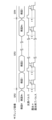
- FIG. 10 shows a timing chart regarding distance measurement operations during one frame period of pixels according to the second embodiment.
- the imaging element (light receiving sensor 2) of FIG. 5 and the pixel 30 of Fig.4 (a) are used.
- the timing signal generator 4 inputs the light emission signal indicating the light emission timing of the light source 1 to the sensor timing generator 25 .
- the sensor timing generator 25 outputs each signal according to the light emission signal.
- the amount of reflected light from the subject is large. (Decrease current source mode).
- time t0 to time t2 The operation from time t0 to time t2 is the same as in FIG.
- exposure is started after a delay time ( ⁇ 3 in the subrange image SR3) corresponding to the flight distance to the center of each subrange.
- a delay time ⁇ 3 in the subrange image SR3
- exposure starts at times t3, t6 and t9, and ends at times t5, t8 and t10.
- These exposure cycles are the same as the light emission cycle of the light source 1 .
- the exposure end time at this time is set so that the exposure period is a time ⁇ T' longer than the charge discharge time ⁇ T determined by Equation (6). That is, the exposure time of the charge emission source transistor 342 is set in consideration of the quenching time when photons are detected in the latter half of the exposure period.
- the charge emission source transistor 342 operates in constant current mode by constantly applying a fixed bias voltage to the source. As a result, it is possible to count a small number of photons while maintaining the linearity of the charge capacity.
- the distance measuring apparatus switches the charge emission source transistor 342 between the decreasing current source mode and the constant current mode according to the number of photons to be detected from short distance to long distance. Since it can be switched to the source mode, high-precision ranging is realized by photon counting with a high dynamic range.
Abstract
This imaging element comprises a light source (1) and a plurality of pixels (30). The pixels (30) each include: a light receiving element (31); a first capacitance (37); and a charge emission device (34) that is provided inside the pixel (30) and that emits an electric charge to the first capacitance (37) for a certain period of time ΔT when the light receiving element (31) detects light emitted by the light source (1) and reflected by a subject.
Description
本開示は、撮像素子および測距装置に関する。
The present disclosure relates to an imaging device and a distance measuring device.
複数のシングルフォトンアバランシェダイオード(SPAD,Single Photon Avalanche Diode)を備える受光アレイを用いて、被写体までの距離を計測する測距装置や測距システムが存在する。
There are distance measuring devices and distance measuring systems that measure the distance to the subject using a light receiving array equipped with multiple single photon avalanche diodes (SPAD).
例えば、特許文献1の測距装置は、制御部と距離算出部とを備える。制御部は、距離測定を実施する距離範囲を決定し、この距離範囲に対応する時間範囲を複数の区間に分割する。制御部は、時間範囲ごとにパルス光の出射と、受光部の露光が行なわれるように測距装置を制御する。そして、距離算出部が受光部の露光結果に応じて、被写体までの距離を算出する。このときの測距精度は、発光部が照射するパルス光のパルス幅によって決定される。
For example, the distance measuring device of Patent Document 1 includes a control section and a distance calculation section. The control unit determines a distance range for performing distance measurement, and divides a time range corresponding to this distance range into a plurality of intervals. The control unit controls the distance measuring device so that the pulsed light is emitted and the light receiving unit is exposed for each time range. Then, the distance calculation section calculates the distance to the subject according to the exposure result of the light receiving section. The distance measurement accuracy at this time is determined by the pulse width of the pulsed light emitted by the light emitting unit.
ところで、特許文献1のような測距装置には、1の露光期間に複数のパルス光を照射して、被写体に反射した光(フォトン)が計数するフォトンカウンティングを行う受光部が用いられることがある。このような受光部では、画素内に容量を備えており、受光したフォトン数に対応する電荷量が容量に蓄積される。
By the way, a distance measuring device such as that disclosed in Patent Document 1 may use a light receiving unit that performs photon counting, in which a plurality of pulsed light beams are emitted during one exposure period and the light beams (photons) reflected by the subject are counted. be. In such a light receiving portion, a capacitor is provided in each pixel, and the charge amount corresponding to the number of received photons is accumulated in the capacitor.
このような受光部は、フォトンカウンティング数値と対応する実物理量(電荷量)の非線形圧縮率が不十分であるため、背景光が強い環境下において高いダイナミックレンジでのフォトカウンティングが困難となる。
In such a light receiving part, the nonlinear compression rate of the photon counting value and the corresponding real physical quantity (charge amount) is insufficient, so it is difficult to perform photo counting with a high dynamic range in an environment with strong background light.
本開示は、高いダイナミックレンジでのフォトカウンティングが可能となる撮像素子および測距装置を提供することを目的とする。
An object of the present disclosure is to provide an imaging device and a distance measuring device that enable photo counting in a high dynamic range.
前記課題を解決するために、本開示の一実施形態に係る撮像素子は、複数の画素を備え、前記各画素は、受光素子と、第1蓄電素子と、前記各画素内に設けられ、前記受光素子が光源によって照射され被写体で反射された光を検出した場合、前記第1蓄積素子に一定時間電荷を放出する電荷放出装置とを備える、撮像素子。
In order to solve the above problems, an imaging device according to an embodiment of the present disclosure includes a plurality of pixels, each pixel includes a light receiving device, a first storage device, and each pixel provided therein, and a charge discharge device that discharges charges to the first storage element for a certain period of time when the light receiving element detects light irradiated by a light source and reflected by an object.
本開示によると、高いダイナミックレンジでのフォトカウンティングが可能となる。
According to the present disclosure, photo counting with a high dynamic range is possible.
以下、本発明の実施形態を図面に基づいて詳細に説明する。以下の好ましい実施形態の説明は、本質的に例示に過ぎず、本発明、その適用物或いはその用途を制限することを意図するものではない。
Hereinafter, embodiments of the present invention will be described in detail based on the drawings. The following description of preferred embodiments is merely exemplary in nature and is not intended to limit the invention, its applications or uses.
(第1実施形態)
-画素の構成-
図1は、第1実施形態に係る画素の構成を示すブロック図である。図1に示す画素30は、後述する測距装置の受光センサ2(撮像素子)に配置されるものである。 (First embodiment)
- Pixel configuration -
FIG. 1 is a block diagram showing the configuration of a pixel according to the first embodiment.Pixels 30 shown in FIG. 1 are arranged in a light receiving sensor 2 (imaging device) of a distance measuring device, which will be described later.
-画素の構成-
図1は、第1実施形態に係る画素の構成を示すブロック図である。図1に示す画素30は、後述する測距装置の受光センサ2(撮像素子)に配置されるものである。 (First embodiment)
- Pixel configuration -
FIG. 1 is a block diagram showing the configuration of a pixel according to the first embodiment.
図1に示すように、画素30は、受光素子31と、リセットトランジスタ32と、フォトカウント制御回路33と、電荷放出装置34と、ソースフォロアトランジスタ35と、選択トランジスタ36と、第1容量37(第1蓄電素子)とを備える。なお、リセットタイミング制御装置38および電荷供給装置39は、画素30外に配置される。
As shown in FIG. 1, the pixel 30 includes a light receiving element 31, a reset transistor 32, a photocount control circuit 33, a charge discharge device 34, a source follower transistor 35, a selection transistor 36, and a first capacitor 37 ( a first storage element). Note that the reset timing control device 38 and the charge supply device 39 are arranged outside the pixel 30 .
受光素子31は、例えば、SPADやアバランシェフォトダイオード(APD)などのフォトダイオード(PD)である。
The light receiving element 31 is, for example, a photodiode (PD) such as a SPAD or an avalanche photodiode (APD).
リセットトランジスタ32は、ソース(またはドレイン)にリセットタイミング制御装置38の出力端子が接続され、ドレイン(またはソース)に受光素子31のカソード端子およびフォトカウント制御回路33の入力端子が接続され、ゲートにリセット信号VRSTを受ける。リセットタイミング制御装置38は、リセットトランジスタ32が受光素子31などのリセットを行うための電圧を、リセットトランジスタ32に供給する。
The reset transistor 32 has a source (or drain) connected to the output terminal of the reset timing control device 38, a drain (or source) connected to the cathode terminal of the light receiving element 31 and the input terminal of the photocount control circuit 33, and a gate Receives reset signal V RST . The reset timing control device 38 supplies a voltage for the reset transistor 32 to reset the light receiving element 31 and the like to the reset transistor 32 .
フォトカウント制御回路33は、出力端子に、電荷放出装置34の入力端子が接続される。フォトカウント制御回路33は、受光素子31のカソード端子からの出力に応じて、フォトカウンティング動作を行い、その結果を出力端子から出力する。例えば、フォトカウント制御回路33は、受光素子31が光(フォトン)を検出した場合に、パルス電圧を電荷放出装置34に出力する。
The input terminal of the charge discharge device 34 is connected to the output terminal of the photocount control circuit 33 . The photocount control circuit 33 performs a photocounting operation according to the output from the cathode terminal of the light receiving element 31, and outputs the result from the output terminal. For example, the photocount control circuit 33 outputs a pulse voltage to the charge discharge device 34 when the light receiving element 31 detects light (photons).
電荷放出装置34は、フォトカウント制御回路33および電荷供給装置39からの信号を受け、フローティングディフュージョンFDに電荷を出力する。例えば、電荷放出装置34は、フォトカウント制御回路33がパルス電圧を出力した場合に、所定の電荷をFDに出力する。電荷供給装置39は、電荷放出装置34に出力するための電荷を供給する。
The charge discharge device 34 receives signals from the photocount control circuit 33 and the charge supply device 39 and outputs charges to the floating diffusion FD. For example, the charge discharge device 34 outputs a predetermined charge to the FD when the photocount control circuit 33 outputs a pulse voltage. The charge supply device 39 supplies charges for output to the charge discharge device 34 .
ソースフォロアトランジスタ35は、ソース(またはドレイン)に画素電源バイアス信号Vcを受け、ドレイン(またはソース)に選択トランジスタ36のソース(またはドレイン)が接続され、ゲートにFDが接続される。
The source follower transistor 35 receives the pixel power supply bias signal Vc at its source (or drain), has its drain (or source) connected to the source (or drain) of the selection transistor 36, and has its gate connected to FD.
選択トランジスタ36は、ドレイン(またはソース)に出力線26が接続され、ゲートに選択信号VSELを受ける。
The select transistor 36 has a drain (or source) connected to the output line 26 and a gate receiving a select signal V SEL .
第1容量37は、一端がFDに接続され、他端が接地電圧(アース)に接続される。第1容量37は、電荷放出装置34がFDに出力した電荷を蓄積する。
The first capacitor 37 has one end connected to the FD and the other end connected to the ground voltage (earth). The first capacitor 37 accumulates the charge output from the charge discharge device 34 to the FD.
ソースフォロアトランジスタ35は、選択トランジスタ36がオン状態となった場合、第1容量37に蓄積された電荷に応じた画素信号を、出力線26に出力する。
The source follower transistor 35 outputs a pixel signal corresponding to the charge accumulated in the first capacitor 37 to the output line 26 when the selection transistor 36 is turned on.
ここで、特許文献1における、FDの容量をCF、蓄積用容量の容量をCM、両者の比をrM=CM/(CF+CM)とし、各フォトン検出時にFDに飽和電荷量Q0が転送されるものとすると、i個目のフォトン検出時において、蓄積用容量に追加蓄積される電荷量はrM
iQ0である。したがって、フォトンm個を検出した場合に蓄積用容量に蓄積される総電荷量は
Here, let C F be the capacity of the FD, C M be the capacity of the storage capacitor, and r M = C M /(C F + C M ) be the ratio of the two in Patent Document 1, and let the FD be saturated charge when each photon is detected. Assuming that the amount Q 0 is transferred, the amount of charge additionally stored in the storage capacitor is r M i Q 0 when the i-th photon is detected. Therefore, the total charge accumulated in the storage capacitor when m photons are detected is
となる。ここで、rMが1に近いほど高いフォトン計数値を得ることが可能である。しかし、画素サイズ5μm程度の実用的に高解像度が可能な条件においては、rM=0.9が限界値であり、画素内に蓄積可能なフォトン数の最高計数値は15程度に留まる。
becomes. Here, it is possible to obtain a higher photon count value as r M is closer to 1. However, under the condition that the pixel size is about 5 μm and a practically high resolution is possible, r M =0.9 is the limit value, and the maximum count value of the number of photons that can be accumulated in the pixel remains at about 15.
本実施形態において、フォトン数の最小計数値1から30程度までの高ダイナミックレンジを得るためには、電荷放出装置34からFDに出力される電荷量が少ないこと好ましい。ところで、電荷放出装置34からFDに出力される電荷量の最小値は、第1容量37を充放電する際に発生するkTCノイズで規定されており、典型的な値としてC=15fF、室温で約63電子となる。本実施形態において、有効なS/N比を2と仮定した場合、画素信号を出力するために必要な電荷量は約125電子となる。このような微小な電荷量をフォトン計数毎に蓄積制御する場合、電荷放出装置34には、(1)微小電流(典型的には10nA)を、(2)超短時間(典型的には2ns)だけ流す精密な回路が必要となる。しかしながら、(1)、(2)を同時に満たすことは、量産工程で発生する寄生成分のばらつきを考慮すると、実現は極めて困難である。そこで、第1容量37に微小電流を流入させ、フォトン計数値の増分に従って、第1容量37に一定比率の電荷量を蓄積する(減少させる)ことが可能であれば、高計数値領域において信号電荷量が圧縮されるため、実電圧値を変えることなく、撮像素子のダイナミックレンジを高い値に広げることが可能となる。
In this embodiment, in order to obtain a high dynamic range from the minimum photon count value of 1 to about 30, it is preferable that the amount of charge output from the charge emission device 34 to the FD is small. By the way, the minimum value of the amount of charge output from the charge discharge device 34 to the FD is defined by kTC noise generated when the first capacitor 37 is charged and discharged. It becomes about 63 electrons. In this embodiment, assuming an effective S/N ratio of 2, the amount of charge required to output a pixel signal is approximately 125 electrons. In the case of controlling the accumulation of such a minute amount of charge for each photon count, the charge discharge device 34 needs (1) a minute current (typically 10 nA) and (2) an extremely short time (typically 2 ns). ) is required. However, it is extremely difficult to satisfy (1) and (2) at the same time, considering variations in parasitic components occurring in the mass production process. Therefore, if it is possible to cause a minute current to flow into the first capacitor 37 and accumulate (decrease) the charge amount at a constant ratio in the first capacitor 37 according to the increment of the photon count value, the signal Since the charge amount is compressed, the dynamic range of the image sensor can be extended to a high value without changing the actual voltage value.
図2は、第1実施形態に係る電荷放出装置の動作原理を説明するための図である。電荷放出装置34は、例えば、ソース(またはドレイン)に容量(ここでは、第2容量343とする)が接続され、ドレイン(またはソース)に第1容量37が接続されたMOSFETである。第2容量343に一定量の電荷を充電しておき、MOSFETをサブスレッショルド領域で動作させるによって、電荷放出装置34はドレイン(第1容量37)に微小電流を出力する。例えば、受光素子31がフォトンを1個検出するたびに、MOSFETのゲートに所定のバイアス電圧が印加されると、電荷放出装置34は、ソースからドレインに電荷を一定時間、放出する。
FIG. 2 is a diagram for explaining the principle of operation of the charge emission device according to the first embodiment. The charge discharge device 34 is, for example, a MOSFET having a source (or drain) connected to a capacitor (here, a second capacitor 343) and a drain (or source) connected to the first capacitor 37. FIG. By charging the second capacitor 343 with a certain amount of charge and operating the MOSFET in the subthreshold region, the charge discharge device 34 outputs a minute current to the drain (first capacitor 37). For example, when a predetermined bias voltage is applied to the gate of the MOSFET each time the light receiving element 31 detects one photon, the charge discharge device 34 discharges charges from the source to the drain for a certain period of time.
図3は、第1実施形態に係る電荷放出装置34のポテンシャルダイアグラムの概略図である。図3において、n,kは初期状態から起算して、第2容量343から放出された電子数を表すパラメータである。図3では、第2容量343からk個の電子を放出した状態にあり、ゲートに所定のバイアス電圧が印加されているときのMOSFETの状態をSkと称する。MOSFETが状態Skにあるときの第2容量343からの電荷の平均放出レートをλkとする。第2容量343が1個も電荷を放出していない初期状態S0における平均放出レートをλ0とする。このとき、MOSFETのソースが浮遊状態、チャネルに所定のバイアス電圧が印加されると、MOSFETが状態Skにあるときソース-チャネル間の電圧障壁は初期状態よりもVk=kq/CF高い。したがって、このときの電荷放出レートはボルツマンファクターを考慮して、
FIG. 3 is a schematic diagram of a potential diagram of the charge emission device 34 according to the first embodiment. In FIG. 3, n and k are parameters representing the number of electrons emitted from the second capacitor 343 from the initial state. In FIG. 3, the state of the MOSFET when k electrons are emitted from the second capacitor 343 and a predetermined bias voltage is applied to the gate is referred to as Sk . Let λ k be the average discharge rate of charges from the second capacitor 343 when the MOSFET is in state S k . Let λ 0 be the average emission rate in the initial state S 0 in which no charge is emitted from the second capacitor 343 . At this time, when the source of the MOSFET is in a floating state and a predetermined bias voltage is applied to the channel, the voltage barrier between the source and the channel is V k = kq/C F higher than the initial state when the MOSFET is in the state Sk . . Therefore, considering the Boltzmann factor, the charge emission rate at this time is
となる。
becomes.
ここで、受光素子31が1フォトンを検出するたびに、一定時間ΔT、電荷放出装置34のゲートに所定のバイアス電圧が印加されるものとする。受光素子31の1個目のフォトン検出時に、電荷放出装置34のソースからドレインに放出される電荷をk(1)個とすると、電子がk(1)個放出されるのに要する時間tk(1)=ΔTとなることから、
Here, each time the light receiving element 31 detects one photon, a predetermined bias voltage is applied to the gate of the charge discharge device 34 for a certain period of time ΔT. Assuming that k (1) charges are emitted from the source to the drain of the charge emission device 34 when the light receiving element 31 detects the first photon, the time tk required for k (1) electrons to be emitted. (1) = ΔT, so

となる。同様に、m個目のフォトン検出時に放出される電荷をk(m)個とすると、
becomes. Similarly, if the number of charges emitted upon detection of the m-th photon is k (m), then

となる。したがって、m個のフォトンを計数する間に、電荷放出装置34のソースからドレインに電荷が放出される期間は、動作の設定条件から、m・ΔTである。そこで、tk(1)からtk(m)までの総和をとることによって、電荷放出装置34の電荷放出数の関数が
becomes. Therefore, the period during which charges are emitted from the source to the drain of the charge emission device 34 while counting m photons is m·ΔT from the operating conditions. Therefore, by taking the sum of tk (1) to tk(m) , the function of the charge emission number of the charge emission device 34 is

となる。そして、式(4)をk(m)について解けば、
becomes. Then, solving equation (4) for k(m), we get
となり、MOSFETの電荷放出量がフォトン計数値の関数として求まる。式(5)からわかるように、電荷放出装置34はフォトンの計数値mに対して、電荷放出量k(m)が対数的に圧縮される。したがって、mの値に対して、k(m)の増加が抑圧され、高いm値の計数が可能となる。
and the amount of charge emitted from the MOSFET is obtained as a function of the photon count value. As can be seen from equation (5), the charge emission device 34 has a logarithmically compressed charge emission amount k(m) with respect to the photon count m. Therefore, the increase of k(m) is suppressed for the value of m, and high m values can be counted.
図3は、第1実施形態に係る電荷放出装置のフォトンカウント値と電荷放出量との関係を示している。図3は、第2容量343の容量をCF=15fF、時間ΔT=10ns、初期バイアス電流1μAの場合、電荷放出量k(m)と各カウント値における時間ΔT内に電荷放出装置34から放出される電荷量k(m)-k(m-1)をカウント値mの関数として表示したものである。上述したように、k(m)はmに対して対数的に増加する。CF=15fFの値から電荷量k(m)-k(m-1)がノイズフロアに交差するのはm=35以上である。一定のマージンをとり、本実施例では、m=30までの計数が可能であり、従来の2倍のダイナミックレンジを実現している。
FIG. 3 shows the relationship between the photon count value and the charge emission amount of the charge emission device according to the first embodiment. FIG. 3 shows the charge discharge amount k (m) and the discharge from the charge discharge device 34 within the time ΔT at each count value when the capacitance of the second capacitor 343 is C F =15 fF, the time ΔT=10 ns, and the initial bias current is 1 μA. The amount of charge k(m)-k(m-1) applied is displayed as a function of the count value m. As noted above, k(m) increases logarithmically with m. From a value of C F =15 fF, the amount of charge k(m)−k(m−1) intersects the noise floor at m=35 or more. With a certain margin, this embodiment can count up to m=30, realizing a dynamic range twice as large as the conventional one.
-受光センサの構成-
図4は、第1実施形態に係る受光センサの構成を示すブロック図である。図2に示すように、受光センサ2は、バイアス発生回路20、画素アレイ21、読出回路22、水平出力回路23、垂直駆動回路24、センサタイミング発生器25を備える。 - Configuration of light receiving sensor -
FIG. 4 is a block diagram showing the configuration of the light receiving sensor according to the first embodiment. As shown in FIG. 2, thelight receiving sensor 2 includes a bias generation circuit 20, a pixel array 21, a readout circuit 22, a horizontal output circuit 23, a vertical drive circuit 24, and a sensor timing generator 25. FIG.
図4は、第1実施形態に係る受光センサの構成を示すブロック図である。図2に示すように、受光センサ2は、バイアス発生回路20、画素アレイ21、読出回路22、水平出力回路23、垂直駆動回路24、センサタイミング発生器25を備える。 - Configuration of light receiving sensor -
FIG. 4 is a block diagram showing the configuration of the light receiving sensor according to the first embodiment. As shown in FIG. 2, the
バイアス発生回路20は、受光センサ2を駆動するために必要なバイアス信号(詳細は省略する)を供給する。なお、バイアス信号は、外部から供給する構成としてもよい。
A bias generation circuit 20 supplies a bias signal (details are omitted) necessary for driving the light receiving sensor 2 . Note that the bias signal may be configured to be supplied from the outside.
画素アレイ21は、アレイ状に配置された複数の画素30を備える。複数の画素30は、行ごとに、選択信号VSEL、リセット信号VRST、PDバイアス制御信号VD、電荷充電信号VI、充電制御信号VR、画素電源バイアス信号Vcおよびインバータバイアス信号VINVが供給されている。各画素30は、供給された選択信号VSEL、リセット信号VRST、PDバイアス制御信号VD、電荷充電信号VI、充電制御信号VR、画素電源バイアス信号Vcおよびインバータバイアス信号VINVに応じて、検出結果を示す画素信号を、出力線26に出力する。
The pixel array 21 includes a plurality of pixels 30 arranged in an array. A plurality of pixels 30 are connected to a selection signal V SEL , a reset signal V RST , a PD bias control signal V D , a charge charge signal V I , a charge control signal V R, a pixel power bias signal Vc and an inverter bias signal V INV for each row. is supplied. Each pixel 30 responds to the supplied selection signal V SEL , reset signal V RST , PD bias control signal V D , charge charge signal V I , charge control signal V R , pixel power bias signal Vc and inverter bias signal V INV . Then, a pixel signal indicating the detection result is output to the output line 26 .
読出回路22は、複数の列回路221を備える。列回路221は、増幅器とADコンバータとを備え、複数の画素30の列ごとに設けられる。読出回路22は、出力線26を介して各画素30から出力される信号を、列回路221によって読み出す。
The readout circuit 22 includes multiple column circuits 221 . A column circuit 221 includes an amplifier and an AD converter, and is provided for each column of pixels 30 . The readout circuit 22 reads the signal output from each pixel 30 via the output line 26 by the column circuit 221 .
水平出力回路23は、読出回路22から出力された信号を、出力信号として順次出力する。
The horizontal output circuit 23 sequentially outputs the signals output from the readout circuit 22 as output signals.
垂直駆動回路24は、選択信号VSEL、リセット信号VRST、PDバイアス制御信号VD、電荷充電信号VI、充電制御信号VR、画素電源バイアス信号Vcおよびインバータバイアス信号VINVを生成し、所定のタイミングで各画素30に出力する。
The vertical drive circuit 24 generates a selection signal V SEL , a reset signal V RST , a PD bias control signal V D , a charge charge signal V I , a charge control signal V R, a pixel power bias signal Vc and an inverter bias signal V INV , Output to each pixel 30 at a predetermined timing.
センサタイミング発生器25は、水平出力回路23および垂直駆動回路24の駆動タイミングを示す駆動タイミング信号を出力する。
The sensor timing generator 25 outputs drive timing signals indicating drive timings of the horizontal output circuit 23 and the vertical drive circuit 24 .
-画素に構成される回路例について-
図5(a)は、第1実施形態に係る画素に構成される回路例を示す図である。図5(a)は図1の画素に構成される回路の一例である。図5に示すように、画素30は、受光素子31と、リセットトランジスタ32と、反転アンプトランジスタ331と、負荷トランジスタ332と、充電用トランジスタ341と、電荷放出源トランジスタ342と、第2容量343(第2蓄電素子)と、ソースフォロアトランジスタ35と、選択トランジスタ36と、第1容量37とを備える。図1のフォトカウント制御回路33は、反転アンプトランジスタ331およびデプレション型トランジスタ332で構成されている。図1の電荷放出装置34は、充電用トランジスタ341、電荷放出源トランジスタ342および第2容量343で構成されている。 -Examples of circuits configured in pixels-
FIG. 5A is a diagram showing a circuit example configured in a pixel according to the first embodiment. FIG. 5(a) is an example of a circuit configured in the pixel of FIG. As shown in FIG. 5, thepixel 30 includes a light receiving element 31, a reset transistor 32, an inverting amplifier transistor 331, a load transistor 332, a charging transistor 341, a charge emission source transistor 342, and a second capacitor 343 ( , a source follower transistor 35 , a selection transistor 36 , and a first capacitor 37 . The photocount control circuit 33 in FIG. 1 is composed of an inverting amplifier transistor 331 and a depletion type transistor 332 . The charge discharge device 34 of FIG. 1 is composed of a charging transistor 341 , a charge discharge source transistor 342 and a second capacitor 343 .
図5(a)は、第1実施形態に係る画素に構成される回路例を示す図である。図5(a)は図1の画素に構成される回路の一例である。図5に示すように、画素30は、受光素子31と、リセットトランジスタ32と、反転アンプトランジスタ331と、負荷トランジスタ332と、充電用トランジスタ341と、電荷放出源トランジスタ342と、第2容量343(第2蓄電素子)と、ソースフォロアトランジスタ35と、選択トランジスタ36と、第1容量37とを備える。図1のフォトカウント制御回路33は、反転アンプトランジスタ331およびデプレション型トランジスタ332で構成されている。図1の電荷放出装置34は、充電用トランジスタ341、電荷放出源トランジスタ342および第2容量343で構成されている。 -Examples of circuits configured in pixels-
FIG. 5A is a diagram showing a circuit example configured in a pixel according to the first embodiment. FIG. 5(a) is an example of a circuit configured in the pixel of FIG. As shown in FIG. 5, the
受光素子31は、アノード端子に所定の電圧が入力されている。露光時には、リセットトランジスタ32がオン状態となり、リセットトランジスタ32のドレイン(PDバイアス制御信号VD)と受光素子31のアノード端子との間の電圧が所定のブレークダウン電圧以上に保たれる。一方、非露光時には、リセットトランジスタ32のドレイン(PDバイアス制御信号VD)は0Vに設定され、ソースとして機能し、受光素子31のカソード端子とアノード端子との間の電圧はブレークダウン電圧以下に設定される。これにより、非露光時には、受光素子31にフォトンが入射してもガイガーモードパルスは発生しない。
A predetermined voltage is input to the anode terminal of the light receiving element 31 . During exposure, the reset transistor 32 is turned on, and the voltage between the drain of the reset transistor 32 (PD bias control signal V D ) and the anode terminal of the light receiving element 31 is kept above a predetermined breakdown voltage. On the other hand, during non-exposure, the drain of the reset transistor 32 (PD bias control signal V D ) is set to 0 V and functions as a source, and the voltage between the cathode terminal and the anode terminal of the light receiving element 31 is below the breakdown voltage. set. As a result, during non-exposure, no Geiger mode pulse is generated even if photons are incident on the light receiving element 31 .
反転アンプトランジスタ331は、ソース(またはドレイン)が負荷トランジスタ332のドレイン(またはソース)および電荷放出源トランジスタ342のゲートに接続され、ドレインが接地電圧(アース)に接続され、ゲートがリセットトランジスタ32のドレイン(またはソース)および受光素子31のカソード端子に接続されている。
The inverting amplifier transistor 331 has a source (or drain) connected to the drain (or source) of the load transistor 332 and the gate of the charge emission source transistor 342 , a drain connected to a ground voltage (earth), and a gate connected to the reset transistor 32 . It is connected to the drain (or source) and the cathode terminal of the light receiving element 31 .
負荷トランジスタ332は、ソース(またはドレイン)にインバータバイアス信号VINVを受ける。反転アンプトランジスタ331はデプレション型トランジスタ332を負荷とすることで反転アンプ(インバータ)を構成している。
Load transistor 332 receives inverter bias signal V INV at its source (or drain). The inverting amplifier transistor 331 constitutes an inverting amplifier (inverter) by using the depletion type transistor 332 as a load.
充電用トランジスタ341は、ソース(またはドレイン)に電荷充電信号VIを受け、ゲートに充電制御信号VRを受け、ドレイン(またはソース)に電荷放出源トランジスタ342のソース(またはドレイン)および第2容量343の一端が接続される。電荷放出源トランジスタ342は、ドレイン(またはソース)にFD(図に明示されていない)およびこれと並列に接続された第1容量37(CM)が接続される。第2容量343は他端に接地電圧が接続される。充電用トランジスタ341は、充電制御信号VRにしたがって、第2容量343を所定の電圧に充電する。
The charging transistor 341 receives the charge charging signal VI at its source (or drain), the charge control signal V R at its gate, and the source (or drain) of the charge discharge source transistor 342 and the second V at its drain (or source). One end of the capacitor 343 is connected. The charge emission source transistor 342 has a drain (or source) connected to an FD (not shown in the drawing) and a first capacitor 37 (CM) connected in parallel with this. A ground voltage is connected to the other end of the second capacitor 343 . The charging transistor 341 charges the second capacitor 343 to a predetermined voltage according to the charging control signal VR .
ここで、露光時に受光素子31にフォトンが1個入射し、アバランシェ増倍によってガイガーモードパルスが発生すると、受光素子31のカソード端子の電圧は瞬時に低下する。そして、受光素子31のカソード端子の電圧は、時定数RP・CS(CSは受光素子31と配線の容量、RPはとリセットトランジスタ32のチャネルおよび配線の総抵抗(クエンチング抵抗に相当))経過後、リセットトランジスタ32のソース(PDバイアス制御信号VD)から供給される電圧に自動的に復帰する(図5(b)参照)。すなわち、受光素子31は、セルフクエンチングかつセルフリカバリ動作を行う。この受光素子31のアノード端子の電圧をインバータ(フォトカウント制御回路33:反転アンプトランジスタ331およびデプレション型トランジスタ332)に入力することによって、インバータは、インバータの閾値によって決まる一定時間ΔTの幅を持つ矩形波信号を生成する(図5(c)参照)。具体的には、受光素子31のアノード端子の電圧を、反転アンプトランジスタ331のゲートに入力することにより、前記矩形波信号が電荷放出源トランジスタ342のゲートに出力される。すなわち、一定時間ΔTは、aをパラメータとして
Here, when one photon is incident on the light receiving element 31 during exposure and a Geiger mode pulse is generated by avalanche multiplication, the voltage of the cathode terminal of the light receiving element 31 drops instantaneously. The voltage at the cathode terminal of the light receiving element 31 is the time constant R P ·C S (C S is the capacitance of the light receiving element 31 and wiring, and R P is the total resistance of the channel and wiring of the reset transistor 32 (quenching resistance). equivalent)), the voltage supplied from the source of the reset transistor 32 (PD bias control signal V D ) is automatically restored (see FIG. 5B). That is, the light receiving element 31 performs self-quenching and self-recovery operations. By inputting the voltage of the anode terminal of the light-receiving element 31 to the inverter (photocount control circuit 33: inverting amplifier transistor 331 and depletion type transistor 332), the inverter has a certain width of ΔT determined by the threshold value of the inverter. A square wave signal is generated (see FIG. 5(c)). Specifically, by inputting the voltage of the anode terminal of the light receiving element 31 to the gate of the inverting amplifier transistor 331 , the rectangular wave signal is output to the gate of the charge emission source transistor 342 . That is, the constant time ΔT is given by using a as a parameter
と定まる。すなわち、画素30内に、容量CS、抵抗RPおよびインバータによって一定時間ΔTだけ高電圧となる矩形波信号を生成する回路が構成される。この矩形波信号を電荷放出源トランジスタ342のゲートに入力することによって、一定時間ΔTだけ電荷放出源トランジスタ342がオン状態となる。すなわち、受光素子31がフォトンを受光すると、電荷放出源トランジスタ342は、一定時間ΔTの間に、所定の電圧で充電された第2容量343から、第1容量37に電子を放出することとなる。
determined. That is, in the pixel 30, a circuit that generates a rectangular wave signal that has a high voltage for a certain period of time ΔT is configured by the capacitor C S , the resistor R P and the inverter. By inputting this rectangular wave signal to the gate of the charge emission source transistor 342, the charge emission source transistor 342 is turned on for a certain period of time ΔT. That is, when the light receiving element 31 receives photons, the charge emission source transistor 342 emits electrons from the second capacitor 343 charged with a predetermined voltage to the first capacitor 37 for a certain time ΔT. .
ここで、第2容量343の充電電圧が電荷放出源トランジスタ342のサブスレッショルド電圧以下となるように設定することで、電荷放出源トランジスタ342の電荷放出レートを式(1)で表される状態に設定することができる。これにより、画素30は、式(5)に従う電荷蓄積量k(m)をフォトン計数mに対して得ることが可能となるため、フォトン計数値が30程度までの高い値を得ることが可能となる。この電荷蓄積量に対応した電圧が、ソースフォロアトランジスタ35および選択トランジスタ36によって、画素30から読み出され、列増幅回路40(逆対数変換回路)によって増幅されて出力される。列増幅回路40には、逆対数変換回路が構成されており、式(5)で表される電荷量に対応する電圧をフォトン計数mに対して線形な関数として出力する。
Here, by setting the charge voltage of the second capacitor 343 to be equal to or lower than the subthreshold voltage of the charge emission source transistor 342, the charge emission rate of the charge emission source transistor 342 is brought to the state represented by the formula (1). Can be set. As a result, the pixel 30 can obtain the charge storage amount k(m) according to the formula (5) with respect to the photon count m, so that the photon count value can obtain a high value up to about 30. Become. A voltage corresponding to this charge accumulation amount is read from the pixel 30 by the source follower transistor 35 and the selection transistor 36, amplified by the column amplifier circuit 40 (inverse logarithmic conversion circuit), and output. The column amplifier circuit 40 includes an anti-logarithmic conversion circuit, which outputs a voltage corresponding to the amount of charge represented by Equation (5) as a linear function of the photon count m.
-画素の動作について-
図6は、第1実施形態に係る画素の1フレーム期間中の測距動作に関するタイミングチャートを示す。図6では、上から順に、リセット信号VRST、PDバイアス制御信号VD、電荷放出源トランジスタ342のゲート電圧VEG、充電制御信号VR、電荷充電信号VI、第2容量343の充電電圧VCF、第1容量の充電電圧VCMをそれぞれ示す。なお、光源1の駆動信号は、タイミング信号発生器4からの信号を受けた垂直駆動回路24が生成する。また、受光素子31は、露光時には、カソード端子に、リセットトランジスタ32がソースに受けるPDバイアス制御信号VDが入力され、アノード端子に入力される所定の電圧との差によって生じる電圧がブレークダウン電圧を1V程度超過する、ガイガーモードにバイアスされるものとする。 -About pixel operation-
FIG. 6 shows a timing chart relating to distance measurement operations during one frame period of pixels according to the first embodiment. 6, reset signal V RST , PD bias control signal V D , gate voltage V EG of chargeemission source transistor 342 , charge control signal V R , charge charge signal V I , charge voltage of second capacitor 343 are shown in order from the top. V CF and the charging voltage V CM of the first capacitor respectively. The drive signal for the light source 1 is generated by the vertical drive circuit 24 that receives the signal from the timing signal generator 4 . During exposure, the cathode terminal of the light receiving element 31 receives the PD bias control signal VD received at the source of the reset transistor 32, and the voltage generated by the difference from a predetermined voltage input to the anode terminal is the breakdown voltage. is assumed to be biased in the Geiger mode, exceeding about 1V.
図6は、第1実施形態に係る画素の1フレーム期間中の測距動作に関するタイミングチャートを示す。図6では、上から順に、リセット信号VRST、PDバイアス制御信号VD、電荷放出源トランジスタ342のゲート電圧VEG、充電制御信号VR、電荷充電信号VI、第2容量343の充電電圧VCF、第1容量の充電電圧VCMをそれぞれ示す。なお、光源1の駆動信号は、タイミング信号発生器4からの信号を受けた垂直駆動回路24が生成する。また、受光素子31は、露光時には、カソード端子に、リセットトランジスタ32がソースに受けるPDバイアス制御信号VDが入力され、アノード端子に入力される所定の電圧との差によって生じる電圧がブレークダウン電圧を1V程度超過する、ガイガーモードにバイアスされるものとする。 -About pixel operation-
FIG. 6 shows a timing chart relating to distance measurement operations during one frame period of pixels according to the first embodiment. 6, reset signal V RST , PD bias control signal V D , gate voltage V EG of charge
初期時刻t0に、リセット信号VRSTがハイレベル(H)となり、リセットトランジスタ32がオン状態となる。また、PDバイアス制御信号VDがローレベル(L)となるため、受光素子31のカソード端子の電圧および反転アンプトランジスタ331のゲート電圧がローレベルとなる。このとき、反転アンプトランジスタ331(インバータ)は、ハイレベルの電圧を電荷放出源トランジスタ342のゲートに出力する。これにより、電荷放出源トランジスタ342は、オン状態となる。また、充電制御信号VRおよび電荷充電信号VIがハイレベルとなる。これにより、充電用トランジスタ341がオン状態となり、第1容量37および第2容量343がハイレベル(H’)に充電される。このとき、第1容量37および第2容量343は、時刻t1以降で設定される電荷充電信号VIのミドルレベルよりも0.5~1.0V程度高い電圧に充電される。
At the initial time t0, the reset signal VRST becomes high level (H), and the reset transistor 32 is turned on. Further, since the PD bias control signal VD becomes low level (L), the voltage of the cathode terminal of the light receiving element 31 and the gate voltage of the inverting amplifier transistor 331 become low level. At this time, the inversion amplifier transistor 331 (inverter) outputs a high level voltage to the gate of the charge emission source transistor 342 . As a result, the charge emission source transistor 342 is turned on. Also, the charge control signal VR and the charge charge signal VI become high level. As a result, the charging transistor 341 is turned on, and the first capacitor 37 and the second capacitor 343 are charged to high level (H'). At this time, the first capacitor 37 and the second capacitor 343 are charged to a voltage about 0.5 to 1.0 V higher than the middle level of the charge charging signal VI set after time t1.
時刻t1において、PDバイアス制御信号VDがハイレベルとなり、受光素子31のカソード端子の電圧および反転アンプトランジスタ331のゲート電圧がハイレベルとなる。これにより、受光素子31が受光可能となる。このとき、反転アンプトランジスタ331(インバータ)は、ローレベルの電圧を電荷放出源トランジスタ342のゲートに出力するため、電荷放出源トランジスタ342がオフ状態となる。このため、第1容量37は、受光素子31がフォトンを検出するまで、ハイレベルの電圧を維持する。また、電荷充電信号VIが中間電圧であるミドルレベル(M)となり、第2容量343がミドルレベルに充電される。
At time t1, the PD bias control signal VD becomes high level, and the voltage of the cathode terminal of the light receiving element 31 and the gate voltage of the inverting amplifier transistor 331 become high level. This enables the light receiving element 31 to receive light. At this time, the inversion amplifier transistor 331 (inverter) outputs a low-level voltage to the gate of the charge emission source transistor 342, so that the charge emission source transistor 342 is turned off. Therefore, the first capacitor 37 maintains a high level voltage until the photodetector 31 detects photons. Also, the charge charging signal VI becomes middle level (M), which is an intermediate voltage, and the second capacitor 343 is charged to the middle level.
時刻t2において、リセット信号VRSTおよび電荷充電信号VIがローレベルとなり、受光素子31、第1容量37および第2容量343の初期化が完了する。
At time t2, the reset signal VRST and the charge charge signal VI become low level, and the initialization of the light receiving element 31, the first capacitor 37 and the second capacitor 343 is completed.
時刻t3において、リセット信号VRSTがハイレベルとなり、リセットトランジスタ32がオン状態となる。これにより、受光素子31のカソード端子にハイレベルの電圧が印加されるため、受光素子31のカソード端子とアノード端子との間にブレーク電圧よりも高い電圧が印加された状態となり、露光が開始される。
At time t3, the reset signal VRST becomes high level, and the reset transistor 32 is turned on. As a result, a high level voltage is applied to the cathode terminal of the light receiving element 31, so that a voltage higher than the break voltage is applied between the cathode terminal and the anode terminal of the light receiving element 31, and exposure is started. be.
本実施形態では、露光期間は、時刻t3からt10までの間である。図6では、時刻t4,t6,t8の直前に、受光素子31が1個のフォトンを検出している。時刻t4、t6、t8において、受光素子31は1個のフォトンを受光した後、ガイガーモードパルスを発生し、さらに、セルフクエンチングかつセルフリカバリすることで、図5(b)の矩形信号を出力する。そして、反転アンプトランジスタ331(インバータ)は、式(6)に従って、一定時間ΔTの矩形パルス(図5(c))を出力する。これにより、ゲート電圧VEGが一定時間ΔTだけハイレベルとなり、電荷放出源トランジスタ342が一定時間ΔTだけオン状態となる。これにより、各期間t4~t5,t6~t7,t8~t9間に、電荷放出源トランジスタ342は、式(5)に従って、第2容量343から第1容量37に、電子を放出する。したがって、第2容量343の充電電圧VCFの電圧が徐々に高くなり、第1容量の充電電圧VCMが徐々に低くなる。各期間t4~t5,t6~t7,t8~t9の電圧の変化は式(5)に示すようにフォトン数に対して対数的に(非線形に)変化する。
In this embodiment, the exposure period is from time t3 to t10. In FIG. 6, the light receiving element 31 detects one photon just before times t4, t6, and t8. At times t4, t6, and t8, the light receiving element 31 receives one photon, generates a Geiger mode pulse, and further performs self-quenching and self-recovery to output a rectangular signal shown in FIG. 5(b). do. Then, the inverting amplifier transistor 331 (inverter) outputs a rectangular pulse (FIG. 5(c)) of a constant time ΔT according to the equation (6). As a result, the gate voltage VEG becomes high level for a certain period of time .DELTA.T, and the charge emission source transistor 342 is turned on for a certain period of time .DELTA.T. As a result, the charge emission source transistor 342 emits electrons from the second capacitor 343 to the first capacitor 37 during each of the periods t4-t5, t6-t7, and t8-t9 according to equation (5). Therefore, the charging voltage VCF of the second capacitor 343 gradually increases, and the charging voltage VCM of the first capacitor gradually decreases. The change in voltage in each period t4-t5, t6-t7, t8-t9 changes logarithmically (non-linearly) with respect to the number of photons as shown in equation (5).
時刻t10において、リセット信号VRSTおよびPDバイアス制御信号VDがローレベルとなり、露光期間を終了する。そして、読み出し期間へ移行し、全画素の読み出しが終了した後、次のフレームに移行する。
At time t10, the reset signal VRST and the PD bias control signal VD go low, ending the exposure period. Then, it shifts to the readout period, and after the readout of all the pixels is completed, it shifts to the next frame.
(第2実施形態)
-測距装置の全体構成-
図7は、第2実施形態に係る測距装置の全体構成の一例を示すブロック図である。図7に示すように、本実施形態に係る測距装置は、光源1と、受光センサ2と、信号処理装置3と、タイミング信号発生器4とを備える。なお、受光センサ2には、第1実施形態の撮像素子(受光センサ2)が用いられる。 (Second embodiment)
-Overall configuration of rangefinder-
FIG. 7 is a block diagram showing an example of the overall configuration of a distance measuring device according to the second embodiment. As shown in FIG. 7, the distance measuring device according to this embodiment includes alight source 1, a light receiving sensor 2, a signal processing device 3, and a timing signal generator 4. As shown in FIG. For the light receiving sensor 2, the imaging element (light receiving sensor 2) of the first embodiment is used.
-測距装置の全体構成-
図7は、第2実施形態に係る測距装置の全体構成の一例を示すブロック図である。図7に示すように、本実施形態に係る測距装置は、光源1と、受光センサ2と、信号処理装置3と、タイミング信号発生器4とを備える。なお、受光センサ2には、第1実施形態の撮像素子(受光センサ2)が用いられる。 (Second embodiment)
-Overall configuration of rangefinder-
FIG. 7 is a block diagram showing an example of the overall configuration of a distance measuring device according to the second embodiment. As shown in FIG. 7, the distance measuring device according to this embodiment includes a
受光センサ2は、光源1によって照射され、被写体で反射された光を受光する。受光センサ2は、受光結果を示す出力信号を信号処理装置3に出力する。
The light receiving sensor 2 receives the light emitted by the light source 1 and reflected by the subject. The light receiving sensor 2 outputs an output signal indicating the light receiving result to the signal processing device 3 .
信号処理装置3は、受光センサ2から受信した信号に基づいて、被写体までの距離を算出する。信号処理装置3は、算出結果を示す信号を出力する。
The signal processing device 3 calculates the distance to the subject based on the signal received from the light receiving sensor 2. The signal processing device 3 outputs a signal indicating the calculation result.
タイミング信号発生器4は、光源1、受光センサ2、信号処理装置3に、それぞれの駆動タイミングを示す信号を出力する。具体的には、タイミング信号発生器4は、光源1、受光センサ2、信号処理装置3が全画素同時撮像(グローバルシャッター)動作をするように、受光センサ2のフレームレートに位相が同期した信号を出力する。なお、タイミング信号発生器4が出力する信号の周波数は互いに異なってもよい。
The timing signal generator 4 outputs to the light source 1, the light receiving sensor 2, and the signal processing device 3 signals indicating their drive timings. Specifically, the timing signal generator 4 generates a signal whose phase is synchronized with the frame rate of the light receiving sensor 2 so that the light source 1, the light receiving sensor 2, and the signal processing device 3 perform an all-pixel simultaneous imaging (global shutter) operation. to output The frequencies of the signals output by the timing signal generator 4 may be different from each other.
-サブレンジ画像について-
図8は、第2実施形態に係る測距装置の距離測定の原理を説明するための図である。第2実施形態に係る測距装置は、サブレンジ(SR)画像SR1~SR5と、サブレンジ画像SR1~SR5からなるフルレンジ(FR)画像FR1とを生成可能である。なお、以下の説明において、上記実施形態と同様の構成については同じ符号を付し、詳細な説明を省略する場合がある。 - About sub-range images -
FIG. 8 is a diagram for explaining the principle of distance measurement by the distance measuring device according to the second embodiment. The distance measuring device according to the second embodiment can generate sub-range (SR) images SR1-SR5 and a full-range (FR) image FR1 composed of sub-range images SR1-SR5. In addition, in the following description, the same code|symbol may be attached|subjected about the structure similar to the said embodiment, and detailed description may be abbreviate|omitted.
例えば、光源1から被写体までの間の距離により、飛行時間(光が、光源1から照射されてから、被写体によって反射され、受光センサ2に戻ってくるまでの時間)が異なる。飛行時間に基づいて、受光センサ2の露光時間を設定することにより、所定の距離における被写体を検出することができる。
For example, the flight time (the time from when the light is emitted from the light source 1 until it is reflected by the subject and returns to the light receiving sensor 2) varies depending on the distance from the light source 1 to the subject. By setting the exposure time of the light receiving sensor 2 based on the time of flight, it is possible to detect a subject at a predetermined distance.
第2実施形態では、各サブレンジにおける露光時間が、光源が発光してから、前後のサブレンジ(例えば、サブレンジ画像SR3であれば、サブレンジ画像SR2,SR4)との間の中央位置に相当する距離の往復飛行時間だけ遅れたタイミングに設定される。露光時間による露光を繰り返す(戻ってくる光(フォトン)を計数する)ことで、各サブレンジに対応する位置におけるフォトン計数値を得ることができる。受光センサ2は、計数値が一定の閾値を超えた場合に被写体があるものとして、所定の出力レベルの信号を出力し、当該サブレンジの画像を生成する。また、受光センサ2は、得られた複数のサブレンジ画像(図8では、サブレンジ画像SR1~SR5)を重ね合わせることによりフルレンジ画像FR1を生成する。
In the second embodiment, the exposure time in each subrange is the distance corresponding to the central position between the light source and the preceding and succeeding subranges (for example, subrange images SR2 and SR4 in the case of subrange image SR3). The timing is set to be delayed by the round-trip flight time. By repeating the exposure with the exposure time (counting the returning light (photons)), the photon count value at the position corresponding to each subrange can be obtained. The light receiving sensor 2 determines that there is an object when the count value exceeds a certain threshold, and outputs a signal of a predetermined output level to generate an image of the subrange. Further, the light receiving sensor 2 generates a full-range image FR1 by superimposing a plurality of obtained sub-range images (sub-range images SR1 to SR5 in FIG. 8).
図9は、第2実施形態に係るサブレンジ画像の生成方法を説明するための図である。図9では、サブレンジ画像SR3の生成タイミングを示している。
FIG. 9 is a diagram for explaining a subrange image generation method according to the second embodiment. FIG. 9 shows the generation timing of the sub-range image SR3.
図9に示すように、第2実施形態では、光源1から光(パルス)が発射されてから、サブレンジ画像SR3に対応する飛行時間に相当する時間τ3(測距期間)だけ遅れたタイミングで、露光+露光終了パルス(立ち上がりが露光開始および立下りが露光終了に相当するパルス)が発生する。すなわち、受光センサ2は、サブレンジ画像SR3を生成する場合、露光+露光終了パルスがハイである期間に露光を行う。受光センサ2は、サブレンジ画像SR3を作成するために、この露光動作を複数回(本実施例ではn回としている)行い、被写体に反射して戻ってきたフォトン数を計数する。
As shown in FIG. 9, in the second embodiment, after the light (pulse) is emitted from the light source 1, at a timing delayed by a time τ3 (ranging period) corresponding to the flight time corresponding to the sub-range image SR3, An exposure+exposure end pulse (a pulse whose rise corresponds to the start of exposure and whose fall corresponds to the end of exposure) is generated. That is, when generating the sub-range image SR3, the light-receiving sensor 2 performs exposure during the period when the exposure+exposure end pulse is high. The light-receiving sensor 2 performs this exposure operation a plurality of times (n times in this embodiment) to create the sub-range image SR3, and counts the number of photons reflected back from the subject.
ここで、サブレンジ画像SR1,SR2,SR3のように被写体までの距離が近い場合における測距では、被写体からの反射光量が多いため、より多数のフォトン数(典型的には20以上)を計数しなければならない。これに対して、サブレンジ画像SR4,SR5のように被写体までの距離が遠い場合における測距では、被写体からの反射光量が少ないため、計数に必要なフォトン数は少なくてよい(典型的には2以下)。従来の技術では、このような、測定距離レンジ毎に異なる広いダイナミックレンジが要求されるフォトン計数値を同一の画素回路で同一フレーム内に測距撮像することは困難であった。
Here, in distance measurement when the distance to the subject is short, as in the sub-range images SR1, SR2, and SR3, the amount of reflected light from the subject is large, so a larger number of photons (typically 20 or more) are counted. There must be. On the other hand, in distance measurement when the distance to the subject is long as in the sub-range images SR4 and SR5, the amount of reflected light from the subject is small, so the number of photons required for counting may be small (typically 2 the following). With the conventional technology, it is difficult to measure the photon count values, which require a wide dynamic range for each measurement distance range, within the same frame using the same pixel circuit.
-画素の動作について-
図10は、第2実施形態に係る画素の1フレーム期間中の測距動作に関するタイミングチャートを示す。なお、第2実施形態では、図5の撮像素子(受光センサ2)および図4(a)の画素30が用いられる。ここで、第2実施形態では、タイミング信号発生器4がセンサタイミング発生器25に、光源1の発光タイミングを示す発光信号を入力する。センサタイミング発生器25は、発光信号に応じて、各信号を出力する。本実施形態では、距離の近い測距を行う場合(例えば、サブレンジ画像SR1,SR2,SR3など)、被写体からの反射光量が多いため、より多数のフォトン数を計数するために、図10の動作(時減少電流源モード)を行う。 -About pixel operation-
FIG. 10 shows a timing chart regarding distance measurement operations during one frame period of pixels according to the second embodiment. In addition, in 2nd Embodiment, the imaging element (light receiving sensor 2) of FIG. 5 and thepixel 30 of Fig.4 (a) are used. Here, in the second embodiment, the timing signal generator 4 inputs the light emission signal indicating the light emission timing of the light source 1 to the sensor timing generator 25 . The sensor timing generator 25 outputs each signal according to the light emission signal. In the present embodiment, when performing distance measurement at a short distance (for example, sub-range images SR1, SR2, SR3, etc.), the amount of reflected light from the subject is large. (Decrease current source mode).
図10は、第2実施形態に係る画素の1フレーム期間中の測距動作に関するタイミングチャートを示す。なお、第2実施形態では、図5の撮像素子(受光センサ2)および図4(a)の画素30が用いられる。ここで、第2実施形態では、タイミング信号発生器4がセンサタイミング発生器25に、光源1の発光タイミングを示す発光信号を入力する。センサタイミング発生器25は、発光信号に応じて、各信号を出力する。本実施形態では、距離の近い測距を行う場合(例えば、サブレンジ画像SR1,SR2,SR3など)、被写体からの反射光量が多いため、より多数のフォトン数を計数するために、図10の動作(時減少電流源モード)を行う。 -About pixel operation-
FIG. 10 shows a timing chart regarding distance measurement operations during one frame period of pixels according to the second embodiment. In addition, in 2nd Embodiment, the imaging element (light receiving sensor 2) of FIG. 5 and the
時刻t0から時刻t2までの動作は図6と同様である。
The operation from time t0 to time t2 is the same as in FIG.
タイミング信号発生器4が発光信号を出力した後(図10には不図示)、各サブレンジの中央までの飛行距離に対応した遅延時間(サブレンジ画像SR3では、τ3)の後に露光を開始する。図10では、時刻t3,t6、t9において露光が開始され、時刻t5,t8,t10において露光が終了する。これらの露光周期は光源1の発光周期と同一である。このときの露光終了時刻は、露光期間が式(6)で決められる電荷放出時間ΔTよりも長い、時間ΔT’となるように設定される。すなわち、露光期間の後半にフォトンを検出した場合におけるクエンチング時間を考慮して、電荷放出源トランジスタ342の露光時間が設定されている。
After the timing signal generator 4 outputs the light emission signal (not shown in FIG. 10), exposure is started after a delay time (τ3 in the subrange image SR3) corresponding to the flight distance to the center of each subrange. In FIG. 10, exposure starts at times t3, t6 and t9, and ends at times t5, t8 and t10. These exposure cycles are the same as the light emission cycle of the light source 1 . The exposure end time at this time is set so that the exposure period is a time ΔT' longer than the charge discharge time ΔT determined by Equation (6). That is, the exposure time of the charge emission source transistor 342 is set in consideration of the quenching time when photons are detected in the latter half of the exposure period.
一方、距離が長い測距(例えば、サブレンジ画像SR4,SR5など)では、写体からの反射光量が少ないため、図10の動作は不要である。具体的には、電荷放出源トランジスタ342は、ソースを常に固定バイアス電圧を印加することによって、定電流モードで動作する。これにより、電荷容量の線形性を保ちつつ、少ないフォトン数の計数を行うことができる。
On the other hand, in distance measurement with a long distance (eg, sub-range images SR4, SR5, etc.), the amount of reflected light from the subject is small, so the operation in FIG. 10 is unnecessary. Specifically, the charge emission source transistor 342 operates in constant current mode by constantly applying a fixed bias voltage to the source. As a result, it is possible to count a small number of photons while maintaining the linearity of the charge capacity.
以上に説明したように、第2実施形態に係る測距装置は、近距離から遠方まで、検出すべきフォトン数の多少に応じて、電荷放出源トランジスタ342を、時減少電流源モードと定電流源モードに切り替えられるため、高いダイナミックレンジのフォトン計数による高精度測距を実現している。
As described above, the distance measuring apparatus according to the second embodiment switches the charge emission source transistor 342 between the decreasing current source mode and the constant current mode according to the number of photons to be detected from short distance to long distance. Since it can be switched to the source mode, high-precision ranging is realized by photon counting with a high dynamic range.
以上のように、本出願において開示する技術の例示として、実施形態について説明した。しかしながら、本開示における技術は、これに限定されず、適宜、変更、置き換え、付加、省略などを行った実施形態にも適用可能である。
As described above, the embodiment has been described as an example of the technology disclosed in this application. However, the technology in the present disclosure is not limited to this, and can also be applied to embodiments in which modifications, replacements, additions, omissions, etc. are made as appropriate.
1 光源
2 受光センサ(撮像素子)
4 タイミング発生器
26 出力線
30 画素
31 受光素子
34 電荷放出装置
37 第1容量(第1蓄電素子)
343 第2容量(第2蓄電素子)
40 列増幅回路(逆対数変換回路) 1light source 2 light receiving sensor (imaging device)
4timing generator 26 output line 30 pixel 31 light receiving element 34 charge discharge device 37 first capacitor (first storage element)
343 second capacitor (second storage element)
40 column amplifier circuit (inverse logarithmic conversion circuit)
2 受光センサ(撮像素子)
4 タイミング発生器
26 出力線
30 画素
31 受光素子
34 電荷放出装置
37 第1容量(第1蓄電素子)
343 第2容量(第2蓄電素子)
40 列増幅回路(逆対数変換回路) 1
4
343 second capacitor (second storage element)
40 column amplifier circuit (inverse logarithmic conversion circuit)
Claims (7)
- 光源と、
複数の画素とを備え
前記各画素は、
受光素子と、
第1蓄電素子と、
前記各画素内に設けられ、前記受光素子が前記光源によって照射され被写体で反射された光を検出した場合、前記第1蓄積素子に一定時間電荷を放出する電荷放出装置と、
を備える、撮像素子。 a light source;
and a plurality of pixels, each pixel comprising:
a light receiving element;
a first storage element;
a charge discharge device provided in each of the pixels, which discharges charges to the first storage element for a certain period of time when the light receiving element detects light irradiated by the light source and reflected by an object;
An image sensor. - 前記一定時間は、前記受光素子が光を検出してから、セルフクエンチングするまでの時間である、請求項1に記載の撮像素子。 The imaging device according to claim 1, wherein the certain period of time is the time from when the light receiving element detects light to when self-quenching occurs.
- 前記電荷放出装置は、
第2蓄電素子を備え、
前記受光素子が光を検出した場合、前記第2蓄積素子から前記第1蓄電素子に前記一定時間、前記電荷を放出し、
前記電荷を放出する前には、前記第2蓄電素子に所定量の前記電荷を蓄積する、請求項1または請求項2に記載の撮像素子。 The charge emission device is
comprising a second storage element,
when the light receiving element detects light, the charge is discharged from the second storage element to the first storage element for the predetermined time;
3. The imaging device according to claim 1, wherein a predetermined amount of said charge is accumulated in said second storage element before discharging said charge. - 前記画素の出力線には、画素信号を逆対数に変換する逆対数変換回路が接続されている、請求項1から3のいずれか1項に記載の撮像素子。 The imaging device according to any one of claims 1 to 3, wherein an inverse logarithmic conversion circuit for converting a pixel signal into an inverse logarithm is connected to the output line of the pixel.
- 前記電荷放出装置は、前記受光素子が検出するフォトン数に応じて、前記第1蓄積素子に前記一定時間、前記電荷を放出するとき減少電流源モード、および、前記第1蓄積素子に定電流を出力する定電流モードのいずれか一方で動作する、請求項1から4のいずれか1項に記載の撮像素子。 According to the number of photons detected by the light-receiving element, the charge-discharging device applies a decreasing current source mode when discharging the charges to the first storage element for the predetermined time and a constant current to the first storage element. The imaging device according to any one of claims 1 to 4, which operates in one of output constant current modes.
- 前記受光素子は、アバランシェフォトダイオードである、請求項1から5のいずれか1項に記載の撮像素子。 The imaging device according to any one of claims 1 to 5, wherein the light receiving device is an avalanche photodiode.
- 請求項1から6のいずれか1項に記載の撮像素子と、
前記複数の画素に対して、露光開始のタイミングを示す露光開始信号を出力するタイミング信号発生器と、
前記複数の画素から出力される画素信号から、被写体までの距離を算出する信号処理装置とを備える、測距装置。 An imaging device according to any one of claims 1 to 6;
a timing signal generator that outputs an exposure start signal indicating the timing of starting exposure to the plurality of pixels;
and a signal processing device that calculates a distance to a subject from pixel signals output from the plurality of pixels.
Priority Applications (1)
| Application Number | Priority Date | Filing Date | Title |
|---|---|---|---|
| JP2023557982A JPWO2023080044A1 (en) | 2021-11-02 | 2022-10-27 |
Applications Claiming Priority (2)
| Application Number | Priority Date | Filing Date | Title |
|---|---|---|---|
| JP2021179342 | 2021-11-02 | ||
| JP2021-179342 | 2021-11-02 |
Publications (1)
| Publication Number | Publication Date |
|---|---|
| WO2023080044A1 true WO2023080044A1 (en) | 2023-05-11 |
Family
ID=86241042
Family Applications (1)
| Application Number | Title | Priority Date | Filing Date |
|---|---|---|---|
| PCT/JP2022/040046 WO2023080044A1 (en) | 2021-11-02 | 2022-10-27 | Imaging element and ranging device |
Country Status (2)
| Country | Link |
|---|---|
| JP (1) | JPWO2023080044A1 (en) |
| WO (1) | WO2023080044A1 (en) |
Citations (3)
| Publication number | Priority date | Publication date | Assignee | Title |
|---|---|---|---|---|
| WO2019186838A1 (en) * | 2018-03-28 | 2019-10-03 | パナソニックIpマネジメント株式会社 | Solid-state imaging element, solid-state imaging device, solid-state imaging system, and method for driving solid-state imaging element |
| JP6910010B2 (en) * | 2016-02-17 | 2021-07-28 | パナソニックIpマネジメント株式会社 | Distance measuring device |
| WO2021199225A1 (en) * | 2020-03-31 | 2021-10-07 | パナソニックIpマネジメント株式会社 | Information processing system, sensor system, information processing method, and program |
-
2022
- 2022-10-27 WO PCT/JP2022/040046 patent/WO2023080044A1/en active Application Filing
- 2022-10-27 JP JP2023557982A patent/JPWO2023080044A1/ja active Pending
Patent Citations (3)
| Publication number | Priority date | Publication date | Assignee | Title |
|---|---|---|---|---|
| JP6910010B2 (en) * | 2016-02-17 | 2021-07-28 | パナソニックIpマネジメント株式会社 | Distance measuring device |
| WO2019186838A1 (en) * | 2018-03-28 | 2019-10-03 | パナソニックIpマネジメント株式会社 | Solid-state imaging element, solid-state imaging device, solid-state imaging system, and method for driving solid-state imaging element |
| WO2021199225A1 (en) * | 2020-03-31 | 2021-10-07 | パナソニックIpマネジメント株式会社 | Information processing system, sensor system, information processing method, and program |
Also Published As
| Publication number | Publication date |
|---|---|
| JPWO2023080044A1 (en) | 2023-05-11 |
Similar Documents
| Publication | Publication Date | Title |
|---|---|---|
| US10812729B2 (en) | Solid-state imaging device | |
| US10838066B2 (en) | Solid-state imaging device, distance measurement device, and distance measurement method | |
| JP6596029B2 (en) | High dynamic range pixel and method for operating the same | |
| US11405577B2 (en) | Distance image measurement device and distance image measurement method | |
| US8716643B2 (en) | Single photon counting image sensor and method | |
| US20180259625A1 (en) | LiDAR Readout Circuit | |
| US8338773B2 (en) | High-speed analog photon counter and method | |
| JP7043218B2 (en) | Optical sensors, distance measuring devices, and electronic devices | |
| US20130248689A1 (en) | Time-delay integration imaging method and apparatus using a high-speed in-pixel analog photon counter | |
| JP2008542706A (en) | Photon counting device | |
| US11159738B2 (en) | Imaging devices with single-photon avalanche diodes having sub-exposures for high dynamic range | |
| JP2013134173A (en) | Range finding system and range finding method | |
| JP6735515B2 (en) | Solid-state imaging device | |
| WO2023080044A1 (en) | Imaging element and ranging device | |
| CN111048540B (en) | Gate-controlled pixel unit and 3D image sensor | |
| US20200408910A1 (en) | Distance measuring method and distance measuring device | |
| WO2023058591A1 (en) | Imaging element and ranging device | |
| US11553150B2 (en) | In pixel time amplifier for LIDAR applications | |
| KR102419012B1 (en) | Low noise image sensor | |
| US11768106B2 (en) | Photoelectric conversion device for counting a pulse signal and measuring a time when a count value is output | |
| WO2023189856A1 (en) | Solid-state imaging device | |
| US20230296741A1 (en) | Distance measurement sensor with multiple memory nodes | |
| US20230057944A1 (en) | Image capturing apparatus having photon detection and control method therefor | |
| JP2022191793A (en) | Distance image pickup device and distance image pickup method | |
| JP5275911B2 (en) | Signal processing apparatus and light detection apparatus |
Legal Events
| Date | Code | Title | Description |
|---|---|---|---|
| 121 | Ep: the epo has been informed by wipo that ep was designated in this application |
Ref document number: 22889864 Country of ref document: EP Kind code of ref document: A1 |
|
| WWE | Wipo information: entry into national phase |
Ref document number: 2023557982 Country of ref document: JP |