WO2023080033A1 - 車輌用灯具 - Google Patents
車輌用灯具 Download PDFInfo
- Publication number
- WO2023080033A1 WO2023080033A1 PCT/JP2022/039980 JP2022039980W WO2023080033A1 WO 2023080033 A1 WO2023080033 A1 WO 2023080033A1 JP 2022039980 W JP2022039980 W JP 2022039980W WO 2023080033 A1 WO2023080033 A1 WO 2023080033A1
- Authority
- WO
- WIPO (PCT)
- Prior art keywords
- light
- light guide
- incident surface
- light source
- emitted
- Prior art date
- Legal status (The legal status is an assumption and is not a legal conclusion. Google has not performed a legal analysis and makes no representation as to the accuracy of the status listed.)
- Ceased
Links
Images







Classifications
-
- F—MECHANICAL ENGINEERING; LIGHTING; HEATING; WEAPONS; BLASTING
- F21—LIGHTING
- F21S—NON-PORTABLE LIGHTING DEVICES; SYSTEMS THEREOF; VEHICLE LIGHTING DEVICES SPECIALLY ADAPTED FOR VEHICLE EXTERIORS
- F21S43/00—Signalling devices specially adapted for vehicle exteriors, e.g. brake lamps, direction indicator lights or reversing lights
- F21S43/20—Signalling devices specially adapted for vehicle exteriors, e.g. brake lamps, direction indicator lights or reversing lights characterised by refractors, transparent cover plates, light guides or filters
- F21S43/235—Light guides
- F21S43/253—Two or more juxtaposed light guides
-
- F—MECHANICAL ENGINEERING; LIGHTING; HEATING; WEAPONS; BLASTING
- F21—LIGHTING
- F21S—NON-PORTABLE LIGHTING DEVICES; SYSTEMS THEREOF; VEHICLE LIGHTING DEVICES SPECIALLY ADAPTED FOR VEHICLE EXTERIORS
- F21S43/00—Signalling devices specially adapted for vehicle exteriors, e.g. brake lamps, direction indicator lights or reversing lights
- F21S43/20—Signalling devices specially adapted for vehicle exteriors, e.g. brake lamps, direction indicator lights or reversing lights characterised by refractors, transparent cover plates, light guides or filters
- F21S43/235—Light guides
-
- F—MECHANICAL ENGINEERING; LIGHTING; HEATING; WEAPONS; BLASTING
- F21—LIGHTING
- F21S—NON-PORTABLE LIGHTING DEVICES; SYSTEMS THEREOF; VEHICLE LIGHTING DEVICES SPECIALLY ADAPTED FOR VEHICLE EXTERIORS
- F21S43/00—Signalling devices specially adapted for vehicle exteriors, e.g. brake lamps, direction indicator lights or reversing lights
- F21S43/20—Signalling devices specially adapted for vehicle exteriors, e.g. brake lamps, direction indicator lights or reversing lights characterised by refractors, transparent cover plates, light guides or filters
- F21S43/235—Light guides
- F21S43/236—Light guides characterised by the shape of the light guide
- F21S43/241—Light guides characterised by the shape of the light guide of complex shape
-
- F—MECHANICAL ENGINEERING; LIGHTING; HEATING; WEAPONS; BLASTING
- F21—LIGHTING
- F21S—NON-PORTABLE LIGHTING DEVICES; SYSTEMS THEREOF; VEHICLE LIGHTING DEVICES SPECIALLY ADAPTED FOR VEHICLE EXTERIORS
- F21S43/00—Signalling devices specially adapted for vehicle exteriors, e.g. brake lamps, direction indicator lights or reversing lights
- F21S43/20—Signalling devices specially adapted for vehicle exteriors, e.g. brake lamps, direction indicator lights or reversing lights characterised by refractors, transparent cover plates, light guides or filters
- F21S43/235—Light guides
- F21S43/249—Light guides with two or more light sources being coupled into the light guide
-
- F—MECHANICAL ENGINEERING; LIGHTING; HEATING; WEAPONS; BLASTING
- F21—LIGHTING
- F21S—NON-PORTABLE LIGHTING DEVICES; SYSTEMS THEREOF; VEHICLE LIGHTING DEVICES SPECIALLY ADAPTED FOR VEHICLE EXTERIORS
- F21S43/00—Signalling devices specially adapted for vehicle exteriors, e.g. brake lamps, direction indicator lights or reversing lights
- F21S43/20—Signalling devices specially adapted for vehicle exteriors, e.g. brake lamps, direction indicator lights or reversing lights characterised by refractors, transparent cover plates, light guides or filters
- F21S43/27—Attachment thereof
-
- F—MECHANICAL ENGINEERING; LIGHTING; HEATING; WEAPONS; BLASTING
- F21—LIGHTING
- F21S—NON-PORTABLE LIGHTING DEVICES; SYSTEMS THEREOF; VEHICLE LIGHTING DEVICES SPECIALLY ADAPTED FOR VEHICLE EXTERIORS
- F21S43/00—Signalling devices specially adapted for vehicle exteriors, e.g. brake lamps, direction indicator lights or reversing lights
- F21S43/50—Signalling devices specially adapted for vehicle exteriors, e.g. brake lamps, direction indicator lights or reversing lights characterised by aesthetic components not otherwise provided for, e.g. decorative trim, partition walls or covers
-
- F—MECHANICAL ENGINEERING; LIGHTING; HEATING; WEAPONS; BLASTING
- F21—LIGHTING
- F21W—INDEXING SCHEME ASSOCIATED WITH SUBCLASSES F21K, F21L, F21S and F21V, RELATING TO USES OR APPLICATIONS OF LIGHTING DEVICES OR SYSTEMS
- F21W2103/00—Exterior vehicle lighting devices for signalling purposes
-
- F—MECHANICAL ENGINEERING; LIGHTING; HEATING; WEAPONS; BLASTING
- F21—LIGHTING
- F21W—INDEXING SCHEME ASSOCIATED WITH SUBCLASSES F21K, F21L, F21S and F21V, RELATING TO USES OR APPLICATIONS OF LIGHTING DEVICES OR SYSTEMS
- F21W2103/00—Exterior vehicle lighting devices for signalling purposes
- F21W2103/10—Position lights
-
- F—MECHANICAL ENGINEERING; LIGHTING; HEATING; WEAPONS; BLASTING
- F21—LIGHTING
- F21W—INDEXING SCHEME ASSOCIATED WITH SUBCLASSES F21K, F21L, F21S and F21V, RELATING TO USES OR APPLICATIONS OF LIGHTING DEVICES OR SYSTEMS
- F21W2103/00—Exterior vehicle lighting devices for signalling purposes
- F21W2103/20—Direction indicator lights
-
- F—MECHANICAL ENGINEERING; LIGHTING; HEATING; WEAPONS; BLASTING
- F21—LIGHTING
- F21W—INDEXING SCHEME ASSOCIATED WITH SUBCLASSES F21K, F21L, F21S and F21V, RELATING TO USES OR APPLICATIONS OF LIGHTING DEVICES OR SYSTEMS
- F21W2103/00—Exterior vehicle lighting devices for signalling purposes
- F21W2103/55—Daytime running lights [DRL]
Definitions
- the present invention relates to a technical field of vehicle lamps having a plurality of light guiding portions for guiding and emitting incident light.
- a vehicle lamp has a light guide body having an incident surface and an exit surface, and a light source for emitting light. There is a type in which the light is emitted toward the outside (see, for example, Patent Document 1).
- a plurality of light guides having a light emitting portion formed in a plane shape or a curved surface shape are arranged in a predetermined direction, and light emitted from the light source is arranged. are respectively guided by a plurality of light guides, and the light is emitted from each of the light emitting portions of the plurality of light guides.
- the width of the light emitting surface, the length of the light emitting surface, the position of the light emitting surface on the light guide, the direction of the light emitting portion of the light guides, etc. By setting a desired mode, it is possible to set various light emission states and improve visibility and designability.
- the object of the vehicle lamp of the present invention is to reduce the manufacturing cost by reducing the number of parts while ensuring high designability.
- a vehicular lamp includes a plurality of first light guiding lens portions arranged in a predetermined direction and separated from each other, each having a first incident surface, and a first light guiding lens portion connecting the adjacent first light guiding lens portions.
- a first light guide body having a connecting portion and integrally formed with the first light guiding lens portion and the first connecting portion;
- a plurality of second light guiding lens portions having incident surfaces and a second connecting portion connecting the adjacent second light guiding lens portions, wherein the second light guiding lens portions and the second light guiding lens portions are connected to each other.
- a second light guide having integrally formed parts; a first light source for emitting light incident from the first incident surface; and a second light guide for emitting light incident from the second incident surface. 2 light sources, and the first light guiding lens portion and the second light guiding lens portion are separated from each other in a predetermined direction and are positioned so as to overlap each other at least partially.
- At least a part of the first light guiding lens portion in the first light guide body formed integrally with each part and the second guide lens portion in the second light guide body formed integrally with each part are provided. Since it overlaps with at least a part of the optical lens part in a separated state, it is possible to reduce the manufacturing cost by reducing the number of parts while ensuring high designability.
- FIG. 1 is a perspective view of a vehicle lamp showing an internal structure;
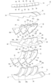
- FIG. It is an exploded perspective view of a marker lamp unit.
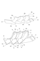
- FIG. 4 is an exploded perspective view of the marker lamp unit viewed from a direction different from that of FIG. 3;
- It is a perspective view of a marker light unit.
- FIG. 6 is a perspective view of the marker light unit viewed from a direction different from that of FIG. 5;
- FIG. 4 is a perspective view showing a state in which each part of the marker light unit is being assembled.
- FIG. 8 is a perspective view showing a state in which each part of the marker light unit is being assembled following FIG.
- FIG. 4 is a perspective view showing a configuration in which light of three different colors is emitted from each light source;
- FIG. 4 is a perspective view showing a light guide lens portion configured by an included portion and a non-included portion;
- FIG. 10 is a perspective view showing a configuration in which a connecting portion that does not contain a light diffusing material is provided in addition to a light guide lens portion that is configured by a containing portion and a non-containing portion.
- the vehicle lamp 1 is attached, for example, to the left and right ends of the rear end of the vehicle body, and is used as a tail lamp, a turn signal lamp, and a welcome lamp.
- the vehicular lamp 1 is not limited to such a combination lamp, and may be a single lamp or a combination lamp that functions at least as a vehicular indicator light as long as it has a plurality of light sources and light guides. good.
- the vehicle lamp 1 can also be used as a clearance lamp, a turn signal lamp, and a daytime running lamp.
- the front, rear, up, down, left, and right directions will be described with reference to the vehicle in which the vehicle lamp 1 is provided.
- the front, rear, up, down, left, and right directions shown below are for convenience of explanation, and the implementation of the present invention is not limited to these directions.
- the central side of the vehicle is defined as the inner side
- the side opposite to the inner side is defined as the outer side
- the light irradiation direction is defined as the front in the front-rear direction.
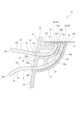
- a vehicle lamp 1 includes, for example, a lamp housing 2 having an opening at its front end and a cover 3 closing the opening of the lamp housing 2 (see FIGS. 1 and 2).
- the vehicle lamp 1 may be formed in such a shape that it is displaced from the front to the rear as it goes from the inner side to the outer side in the left-right direction. 2 openings are formed.
- the lamp housing 2 and the cover 3 constitute a lamp outer casing 4 , and the inner space of the lamp outer casing 4 is formed as a lamp chamber 5 .
- a cover member 6 having a light shielding function is arranged in the lamp chamber 5 (see FIG. 2).
- the cover member 6 functions as a bezel.
- the bezel may be composed of the cover member 6 and the lamp housing 2 .
- the cover member 6 has a plate-like eaves portion 6a facing in a substantially vertical direction and side portions 6b inclined so as to be displaced downward as the eaves portion 6a is separated from the eaves portion 6a.
- the cover member 6 is attached to, for example, the rear surface of the lamp housing 2 and arranged in the lamp chamber 5 .
- a first light guide 9, a second light guide 10, a first extension 11, a second extension 12, a third extension 13, and a substrate 14 are arranged in the lamp chamber 5 (Figs. See Figure 6).
- the first light guide 9, the second light guide 10, the first extension 11, the second extension 12, the third extension 13, and the substrate 14 are configured as a marker light unit 15, and the marker light unit 15 is A part thereof is shielded by the cover member 6, and the shielded part is made invisible from the outside through the cover 3.
- the indicator light unit 15 includes, for example, a first extension 11, a first light guide 9, a second extension 12, a second light guide 10, a third extension 13, and a substrate 14. They are assembled in order from below.
- the first light guide body 9 is integrally formed with a plurality of first light guide lens portions 16 and first connecting portions 17 that connect the plurality of first light guide lens portions 16, respectively.
- the number of the first light guide lens portions 16 in the first light guide 9 is arbitrary as long as it is plural.
- An example of the first light guide 9 provided with 16 and provided with two first connecting portions 17 will be described.
- the first light guiding lens portions 16, 16, 16 are arranged side by side at equal intervals, for example, in the left-right direction.
- the base material of the first light guide 9 is made of, for example, a transparent resin material such as acrylic or polycarbonate, and the resin material contains a light diffusing material. Metal oxide particles such as titanium dioxide particles are used as the light diffusing material.
- the light diffusing material contained in the first light guide 9 is, for example, a so-called fine diffusing material with low diffusivity.
- the average particle size of the light diffusing agent is, for example, 150 nm to 500 nm, preferably 160 nm to 450 nm, more preferably 170 nm to 450 nm, even more preferably 200 nm to 400 nm, and particularly preferably 220 nm to 400 nm.
- the content of the light diffusing material is, for example, 0.1 mass ppm to 100 mass ppm, preferably 0.1 mass ppm to 50 mass ppm, more preferably 0.1 mass ppm to 100 mass ppm, more preferably It is 0.1 mass ppm to 10 mass ppm.
- the first connecting portion 17 may not contain the light diffusing material.
- the first light guide lens portion 16 is provided as a light guide portion 18 except for the rear end portion, and the rear end portion is provided as an attached projection portion 19 projecting backward from the light guide portion 18 .
- the light guide portion 18 is formed, for example, in a shape in which a flat plate is twisted, and is formed in a shape whose width increases toward the front.
- the shape of the light guide portion 18 is arbitrary.
- the width of the substantially rear half portion may be constant and the width of the substantially front half portion may be widened toward the front.
- the light guide portion 18 has a rearmost end surface formed as a first entrance surface 18a and a frontmost end surface formed as a first exit surface 18b.
- the first entrance surface 18a faces upward, and the first exit surface 18b faces forward or diagonally forward (outward).
- the light guide portion 18 is formed in a twisted shape of a flat plate, so that one surface in the thickness direction is a surface facing obliquely upward sideways or obliquely upward forward, and this one surface serves as a second emission surface 18c. formed.
- a reflection step (total reflection step) (not shown) is formed on the other surface of the light guide portion 18 in the thickness direction. Reflection steps (total reflection steps) are also formed on both end faces in the width direction of the light guide portion 18 .
- the attached protrusion 19 protrudes rearward from the rear end portion of the light guide section 18, and has, for example, an upper surface that is flush with the first incident surface 18a.
- the first connecting portion 17 connects two adjacent first light guide lens portions 16, and both left and right ends thereof are connected to the rear end portions of the two adjacent first light guide lens portions 16, respectively.
- the first connecting portion 17 is inclined so as to be displaced rearward as it goes outward in the left-right direction. Therefore, among the adjacent first light guiding lens portions 16, 16, the first light guiding lens portion 16 located on the outer side in the left-right direction is the first light guiding lens portion 16 located on the inner side in the left-right direction. It is positioned backward with respect to the lens portion 16 .
- the second light guide 10 is integrally formed with a plurality of second light guide lens portions 20 and a second connecting portion 21 that connects the plurality of second light guide lens portions 20, respectively.
- the number of the second light guide lens portions 20 in the second light guide body 10 is arbitrary as long as it is plural.
- An example of the second light guide 10 provided with 20 and provided with two second connecting portions 21 will be described.
- it is desirable that the number of the second light guiding lens portions 20 is the same as the number of the first light guiding lens portions 16 .
- the second light guide lens parts 20, 20, 20 are arranged side by side at regular intervals, for example, in the left-right direction.
- the second light guide 10 has a base material made of a transparent resin material such as acrylic or polycarbonate, and the resin material contains a light diffusing material.
- Metal oxide particles such as titanium dioxide particles are used as the light diffusing material.
- the average particle size and content of the light diffusing material are the same as the average particle size and content of the light diffusing material contained in the first light guide 9 .
- the second connecting portion 21 may not contain the light diffusing material.
- the second light guide lens part 20 is provided as a light guide part 22 except for the rear end part, and the rear end part is provided as an attached protrusion 23 projecting forward from the light guide part 22 .
- the light guide part 22 is formed, for example, in a shape in which a flat plate is twisted, and is formed in a shape whose width increases toward the front.
- the shape of the light guide portion 22 is arbitrary, and like the light guide portion 18 of the first light guide lens portion 16, for example, the width of the substantially rear half portion is constant, and the width of the substantially front half portion extends forward. It may be formed in a shape that widens as it goes.
- the light guide portion 22 has a rearmost end surface formed as a second entrance surface 22a and a frontmost end surface formed as a first exit surface 22b.
- the second entrance surface 22a faces upward, and the first exit surface 22b faces forward or diagonally forward (outward).
- the light guide portion 22 is formed in a twisted shape of a flat plate, so that one surface in the thickness direction faces obliquely upward sideways or obliquely upwards forward, and this one surface serves as a second emission surface 22c. formed.
- a reflection step (total reflection step) (not shown) is formed on the other surface of the light guide portion 22 in the thickness direction. Reflection steps (total reflection steps) are also formed on both end faces in the width direction of the light guide portion 22 .
- the attached protrusion 23 protrudes forward from the rear end portion of the light guide section 22, and has, for example, an upper surface that is flush with the second incident surface 22a.
- the second connecting portion 21 connects two adjacent second light guiding lens portions 20, and both left and right ends thereof are connected to the rear end portions of the two adjacent second light guiding lens portions 20, respectively.
- the second connecting portion 21 is inclined so as to be displaced rearward as it goes outward in the left-right direction. Therefore, in the adjacent second light guide lens portions 20, 20, the second light guide lens portion 20 positioned on the outer side in the left-right direction is positioned on the inner side in the left-right direction. It is positioned backward with respect to the lens portion 20 .
- the first extension 11 includes a plate-shaped fastening base portion 24 facing in the vertical direction, an arrangement portion 25 that protrudes upward from the fastening base portion 24 and in which the first light guiding lens portion 16 is arranged, and a front end of the arrangement portion 25. It has a shielding plate portion 26 which is continuous with the portion and extends to the left and right, and fastening protrusions 27, 27 which protrude leftward and rightward from the left and right ends of the shielding plate portion 26, respectively.
- the placement portion 25 is formed with a plurality of placement recesses 25a that are slanted from the top to the front and obliquely downward and are spaced apart from each other in the left and right direction.
- a portion of the upper end surface of the placement portion 25 that is continuous with the placement recess 25a is formed as a mounting surface 25b.
- the shielding plate portion 26 is formed in a gently curved surface convex forward.
- a plurality of insertion cutouts 26a are formed in the upper edge of the shielding plate portion 26 so as to be separated from each other in the left-right direction.
- the second extension 12 includes a placement portion 28 in which the second light guide lens portion 20 is arranged, a shielding plate portion 29 that is continuous with the front end portion of the placement portion 28 and extends left and right, and a left and right extension from both left and right ends of the shielding plate portion 29, respectively. It has fastening protrusions 30, 30 that protrude outward.
- the placement portion 28 is formed with a plurality of placement recesses 28a that are slanted from the top to the front and obliquely downward and are spaced apart from each other to the left and right.
- the upper end surface of the placement portion 28 is formed as a receiving surface 28b.
- the shielding plate portion 29 is formed in a gently curved surface convex forward.
- a plurality of insertion notches 29a are formed in the lower edge of the shielding plate portion 29 so as to be separated in the left-right direction, and a plurality of insertion notches 29b are formed in the upper edge of the shielding plate portion 29 so as to be separated in the left-right direction.
- the third extension 13 is a shielding plate portion 31 extending substantially leftward and rightward, a plurality of mounting projections 32 projecting rearward from the lower end portion of the shielding plate portion 31, and projecting leftward and rightward from both right and left end portions of the shielding plate portion 31, respectively. and fastening projections 33, 33.
- the shielding plate portion 31 is formed in a gently curved surface convex forward.
- a plurality of insertion cutouts 31a are formed in the lower edge of the shielding plate portion 31 so as to be separated from each other in the left-right direction.
- the mounting projection 32 is formed in a substantially triangular shape and has a mounting boss 32a projecting upward.
- the substrate 14 is arranged in the lamp chamber 5 in a state of facing up and down, and is gently curved so as to protrude forward (see FIGS. 3 to 5).
- a plurality of first light sources 34 and a plurality of second light sources 35 are mounted on the lower surface of the substrate 14, respectively.
- the first light source 34 and the second light source 35 are arranged in front and rear two rows and mounted alternately in the left and right direction. Therefore, the first light sources 34 and the second light sources 35 are alternately mounted on the substrate 14 in the horizontal direction of the front row and alternately mounted on the substrate 14 in the horizontal direction of the rear row.
- the marker light unit 15 includes the first extension 11, the first light guide 9, the second extension 12, the second light guide 10, the third extension 13, and the substrate 14. In this way, they are assembled in order from below.
- the first light guide 9 is attached to the first extension 11 from above (see FIG. 7).
- the assembly of the first light guide 9 to the first extension 11 is such that the mounting projections 19, 19, 19 of the first light guide 9 are attached to the mounting surfaces 25b, 25b, 25b of the first extension 11, respectively. It is carried out by being attached by screws or the like.
- the rear portions of the first light guide lens portions 16, 16, 16 are arranged along the recessed portions 25a, 25a, 25a, respectively.
- the front portions of the first light guide lens portions 16, 16, 16 protrude from the insertion cutouts 26a, 26a, 26a to the front side of the shielding plate portion 26, respectively.
- the second extension 12 is attached to the first extension 11 from above (see FIGS. 7 and 8).
- the second extension 12 is assembled to the first extension 11 by placing the shielding plate portion 29 of the second extension 12 on the shielding plate portion 26 of the first extension 11 and fastening the second extension 12 .
- the fastening projections 30, 30 are placed on the fastening projections 27, 27 of the first extension 11, respectively.
- the front portions of the first light guiding lens portions 16, 16, 16 are formed into insertion notches 26a, 26a, 26a and an insertion notch 29a, respectively. , 29a, 29a to the front side of the shielding plate portion 26 and the shielding plate portion 29. As shown in FIG.
- the second light guide 10 is attached to the second extension 12 from above (see FIG. 8).
- the second light guide body 10 is assembled to the second extension 12 by arranging the rear portions of the second light guide lens portions 20, 20, 20 along the arrangement recesses 28a, 28a, 28a, respectively. It is done by In the state where the second light guide body 10 is assembled to the second extension 12, the front portions of the second light guide lens portions 20, 20, 20 are separated from the insertion notches 29b, 29b, 29b, respectively, by the shield plate. The portion 29 is projected forward.
- the third extension 13 is attached to the second extension 12 from above (see FIG. 9).
- the third extension 13 is assembled to the second extension 12 by placing the shielding plate portion 31 of the third extension 13 on the shielding plate portion 29 of the second extension 12 and fastening the third extension 13 .
- the fastening projections 33, 33 are placed on the fastening projections 30, 30 of the second extension 12, respectively.
- each part of the mounting projections 32, 32, 32 of the third extension 13 is positioned below the mounting projections 23, 23, 23 of the second light guide 10, respectively, and the mounting projections 23, 23, 23 are attached to the attachment protrusions 32, 32, 32 by screwing or the like.
- the third extension 13 is attached to the second extension 12 and the second light guide body 10 is attached to the third extension 13, the front side of the second light guide lens portions 20, 20, 20 The portions protrude forward from the shielding plate portions 29 and 31 from the insertion notches 31a, 31a, 31a and the insertion notches 29b, 29b, 29b, respectively.
- the receiving surface 28b of the second extension 12 is the second entrance surface 22a, 22a, 22a of the second light guiding lens portion 20 and the second entrance surface 22a. It is positioned slightly above the first incident surfaces 18 a , 18 a , 18 a of the one light guide lens portion 16 .
- the substrate 14 is assembled with the third extension 13 .
- the board 14 is attached to the third extension 13 by attaching the board 14 to the mounting bosses 32a, 32a, 32a of the third extension 13 by screws or the like.
- the substrate 14 is received from below by the receiving surface 28b of the second extension 12, so that the stable arrangement of the substrate 14 is ensured.
- the first extension 11, the first light guide 9, the second extension 12, the second light guide 10, the third extension 13, and the substrate 14 are assembled in order from below to form a sign.
- the lamp unit 15 is configured, a first light source 34 and a second light source 35 in the front row are positioned facing the second incident surface 22a of the second light guide member 10 from above, and the first light source 34 in the rear row A light source 34 and a second light source 35 are positioned facing the first incident surface 18a of the first light guide 9 from above.
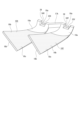
- the first light guide lens portion 16 of the first light guide 9 and the second light guide lens portion 20 of the second light guide 10 are aligned in the horizontal direction. They are positioned alternately, are spaced apart at regular intervals, and are at least partially overlapped in the left-right direction (see FIG. 5).
- the first incident surface 18a of the first light guiding lens portion 16 and the second incident surface 22a of the second light guiding lens portion 20 which are adjacent to each other are arranged side by side in the horizontal direction (FIG. 6). reference).
- the first incident surfaces 18a, 18a, 18a are positioned behind the second incident surfaces 22a, 22a, 22a, respectively (see FIGS. 6 and 9).
- the second incident surface 22a and the first incident surface 18a positioned in front and behind are positioned in front and behind with the upper end portion of the placement portion 28 of the second extension 12 interposed therebetween. Therefore, the second incident surface 22a and the first incident surface 18a positioned in the front and back are located close to each other in the front and rear direction, and accordingly, the first light source 34 and the second light source 35 in the front row and the first light source 35 in the rear row , the distance from the light source 34 and the second light source 35 is reduced.
- the 2nd entrance surface 22a and the 1st entrance surface 18a which are located in front and back at this time may be shifted
- the distance between the first light source 34 and the second light source 35 in the front row and the first light source 34 and the second light source 35 in the rear row is reduced, the distance in the front-rear direction of the substrate 14 is reduced accordingly. , the size of the substrate 14 can be reduced.
- the receiving surface 28b of the second extension 12 is positioned slightly above the second incident surface 22a and the first incident surface 18a, and the first light source 34 and the second light source in the front row 35 and the first light source 34 and the second light source 35 in the rear row are positioned on the opposite side of the second extension 12 with the upper end portion of the arrangement portion 25 interposed therebetween. Therefore, the upper end portion of the placement portion 25 functions as a partition portion 28c that partitions the first and second light sources 34 and 35 in the front row from the first and second light sources 34 and 35 in the rear row.
- the second extension 12 is provided with the partition portion 28c in this manner, the light emitted from the first light source 34 and the second light source 35 in the front row is separated from the first incident surface 18a by the partition portion 28c. is prevented from entering the first light source 34 and the light emitted from the second light source 35 in the rear row from entering the second incident surface 22a. Unnecessary incidence of light from the incident surface 18a and the second incident surface 22a can be prevented.
- the first The rear portion of the second light guide 9, the rear portion of the second light guide 10, and the substrate 14 are shielded from the front side (see FIG. 5).
- the marker light unit 15 includes, for example, the fastening base portion 24 of the first extension 11, the fastening protrusions 27, 27 of the first extension 11, the fastening protrusions 30, 30 of the second extension 12, and the third extension.
- the projections 33, 33 for fastening of the extension 13 are fastened to respective parts of the lamp housing 2 by screwing or the like, so that they are arranged in the lamp chamber 5. As shown in FIG. When the marker lamp unit 15 is arranged in the lamp chamber 5, the light emitted from the first emission surface 18b of the first light guide 9 and the first emission surface 22b of the second light guide 10 is the strongest. is set to face the direction you want to irradiate.
- the first emission surface 18b and the first emission surface 22b are arranged to face the direction in which the strongest light is desired to be emitted, thereby efficiently forming a desired light distribution pattern. becomes possible.
- the emitted light when light is emitted from the first light source 34, the emitted light is transmitted from the first incident surface 18a or the second incident surface 22a to the first light guide. It enters the body 9 or the second light guide 10 and is guided by the light guide section 18 or the light guide section 22 .
- the light guided by the light guide portion 18 is emitted from the first emission surface 18b and the second emission surface 18c, is transmitted through the cover 3, and is irradiated to the outside.
- the light guided by the light guide portion 22 is emitted from the first emission surface 22b and the second emission surface 22c, is transmitted through the cover 3, and is irradiated to the outside.
- the first light guiding lens portion 16 and the second light guiding lens portion 20 contain the light diffusing material, the light from the first light guiding lens portion 16 and the second light guiding lens portion 20 Light is emitted in a diffused state.
- the light is emitted from the second emission surfaces 18c and 22c in addition to the first emission surfaces 18b and 22b.
- the optical body 10 it is possible to adopt a configuration in which the light is emitted from the first emission surfaces 18b and 22b and the light is not emitted from the second emission surfaces 18c and 22c.
- the first light sources 34, 34, . . . and the second light sources 35, 35, . and the second light sources 35, 35, . . . , the first light sources 34, 34, . ⁇ It is possible to change the brightness of the light emitted from each.
- the first light source 34 is turned on to emit red light as a tail lamp
- the second The light source 35 is turned on to emit amber (yellow) light as a turn signal lamp.
- Light as a turn signal lamp can be emitted even in a state in which light from the tail lamp is emitted.
- the first light guiding lens portions 16, 16, 16 and the second light guiding lens portions 20, 20 are arranged in addition to the normal lighting state. , 20 in which the gradation of emitted light is expressed such that the luminance increases in order in the horizontal direction, and the first light guiding lens portions 16, 16, 16 or the second light guiding lens portions 20, 20 , 20 to alternately express high and low luminance in the horizontal direction.
- the vehicle lamp 1 can emit light as a welcome lamp that is lit when the door of the vehicle is unlocked by remote control.
- light can be emitted in various states such as a blinking state and a sequential state within a predetermined time.
- the vehicle lamp 1 is capable of realizing various light emission states.
- a first light guide 9 having a light guide lens portion 16 and a second light guide 10 having a plurality of second light guide lens portions 20 are provided.
- the first light guide body 9 is integrally formed with a plurality of first light guide lens portions 16 and a first connecting portion 17
- the second light guide body 10 is formed with a plurality of second light guide lens portions 16 and a first connecting portion 17.
- the light guiding lens portion 20 and the second connecting portion 21 are integrally formed, and the first light guiding lens portion 16 and the second light guiding lens portion 20 are separated in a predetermined direction and at least partially connected to each other in the horizontal direction. positioned in an overlapping state.
- the first light guide lens portion 16 in the first light guide 9 integrally formed with the respective portions and the second light guide in the second light guide 10 integrally formed with the respective portions Since it overlaps with at least a part of the lens part 20 in a separated state, it is possible to reduce the manufacturing cost by reducing the number of parts while ensuring high designability.
- the light is emitted from the plurality of first light guide lens portions 16 and the plurality of second light guide lens portions 20 that are at least partially overlapped, sufficient brightness is ensured in the irradiation area and the overlap is ensured. High-density feeling and transparency (three-dimensional effect) caused by this can be realized, and an irradiation state of high-brightness light with high designability can be ensured.
- first light guide lens portions 16 and the second light guide lens portions 20 are alternately positioned, the first light guide lens portions 16 and the second light guide lens portions 20 are regularly arranged. It is possible to easily control the lighting and extinguishing of the first light source 34 and the second light source 35 while securing a high degree of design.
- the direction of incidence of light with respect to the first incident surface 18a and the second incident surface 22a is It is possible to arbitrarily set the emission direction of the light emitted from the first light guide 9 and the second light guide 10, so that the degree of freedom in designing the vehicle lamp 1 can be improved. At the same time, the size of the vehicle lamp 1 can be reduced.
- first incident surface 18a and the second incident surface 22a are located at different positions in at least one of the front-rear direction and the left-right direction, and the first light source 34 and the second light source 35 are all mounted on one substrate 14. is installed.
- first extension 11 a first extension 11 a second extension 12 and a third extension 13 are provided to which at least one of the first light guide 9 or the second light guide 10 is attached or held, Two extensions 12 are arranged between the first light guide 9 and the second light guide 10 .
- the first extension 11, the first light guide 9, the second extension 12, the second light guide 10, and the third extension 13 are arranged in order, the first extension 11, the first light guide 9, the second extension 12, the second light guide 10, and the third extension 13 can be assembled in order, and the first extension 11 and the first light guide 9, the second extension 12, the second light guide 10 and the third extension 13 can be assembled with improved workability.
- the first extension 11, the second extension 12, and the third extension 13 are positioned inside the lamp chamber 5, and in addition to the shielding function when viewed from the outside, the first light guide 9 and the function of holding the second light guide 10, the minimum number of engaging portions, ribs, etc. for holding and positioning the first light guide 9 and the second light guide 10 It becomes possible to Therefore, the internal structure of the vehicle lamp 1 can be simplified, and the reflection of light from the engaging portions, ribs, etc., to the first light guide body 9 and the second light guide body 10 can be reduced. It is possible to suppress the incidence of light that does not occur.
- marker light unit 15 can also be configured to have two extensions out of the first extension 11, the second extension 12, and the third extension 13.
- the second light source 35 is turned on to emit amber (yellow) light as a turn signal lamp.
- the tail lamp in order to maintain sufficient chromaticity of light as a turn signal lamp, the tail lamp is in a state of lighting with a small amount of light. Since the light guide lens portion 20 of 2 contains the light diffusing material, the light is diffused by the light diffusing material even when the tail lamp, which is lit with a small amount of light, is lit, and uneven brightness is less likely to occur when the tail lamp is lit. ing.
- a vehicle lamp includes a light guide body having a light guide lens portion formed with an incident surface and an emitting surface, and a light source for emitting light.
- a light guide body having a light guide lens portion formed with an incident surface and an emitting surface
- a light source for emitting light.
- the light is guided by a light guide lens portion and emitted from an emission surface to the outside (see, for example, Japanese Patent Application Laid-Open No. 2021-51950).
- light sources are arranged to face the two incident surfaces of the light guide, respectively.
- the light emitted from the other light source and guided by the light guide is emitted from the emission surface of the light guide as the light of the turn signal lamp, for example. It is
- a vehicle lamp that uses a light guide as described above to function as a lamp with different functions, it may be lit with a small amount of light depending on the function to be executed. There is a risk that uneven brightness will occur in the light emitted from the body.
- the light amount of the other light may be reduced. Also in this case, since the light amount of the other light is small, uneven brightness may occur.
- the first light guide lens portion 16 and the second light guide lens portion 20 contain a light diffusing material, and the light emitted from the first light source 34 and the second light source 35 are different colors.
- Light is incident from different portions on the first incident surface 18a or the second incident surface 22a, and light of different colors incident from the first incident surface 18a or the second incident surface 22a passes through the first light guide lens.
- the light is emitted in a mixed color state inside the portion 16 and the second light guiding lens portion 20 .
- the light emitted from the first light source 34 and the second light source 35 and entered from different portions of the first incident surface 18a or the second incident surface 22a and mixed in color is diffused by the light diffusing material. Since the light is emitted from the first light guide lens portion 16 and the second light guide lens portion 20, it is possible to prevent uneven luminance from occurring regardless of the lighting states of the first light source 34 and the second light source 35. .
- the high-brightness light emitted by the turn signal lamp emitted by the lighting of the second light source 35 is also diffused by the light diffusing material, it is difficult to cause a so-called flashing state in which a part of the lamp has a high brightness. It is also possible to prevent the occurrence of luminance unevenness in the lighting state of the second light source 35 .
- a first light source 36, a second light source 37, and a third light source 38 which respectively emit lights of different colors, are provided. may be mounted on the substrate 14 (see FIG. 10).
- light emitted from the first light source 36, the second light source 37, and the third light source 38 passes through the first incident surface 18a or the second incident surface 22a to the first light guide 9 or It is incident on the second light guide 10 .
- red light, green light, and blue light are emitted from the first light source 36, the second light source 37, and the third light source 38, respectively.
- two or three of the first light source 36, the second light source 37, and the third light source 38 are turned on at the same time, so that the mixed light is emitted to the first light guide 9 or the second light source 38. is emitted from the light guide 10 of . Therefore, by adjusting the brightness of each emitted light or changing the combination of the light sources to be lit, light of various colors can be emitted from the first light guide 9 or the second light guide 10 to obtain an emission state. It is possible to perform various different productions.
- one of the first light source 36, the second light source 37, and the third light source 38 emits red light and the other light source emits amber light
- the other light source emits amber light
- the vehicle lamp 1 is capable of controlling the current value supplied to the first light source 34 and the second light source 35 .
- the first light guide 9 or the second light guide Since the output area of the light from the body 10 gradually increases from the side of the first incident surface 18a or the second incident surface 22a toward the side of the first output surfaces 18b and 22b, it is as if the light is emitted from the rear to the front. It looks like it's moving. Further, by repeating the control of gradually increasing the current value supplied to the second light source 35 and then gradually decreasing it, the light appears to expand and contract in the front-rear direction.
- the vehicle lamp by controlling the current value in this way, it is possible to perform a sophisticated effect of the emission state in which the light moves.
- Such an effect is particularly suitable when emitting the light of a turn signal lamp or the light of a welcome lamp.
- the output state of the light incident from the first light entrance surface 18a or the second light entrance surface 22a from the first light guide lens portion 16 or the second light guide lens portion 20 changes according to the change in the light amount. Since it changes, it is possible to realize a desired light emission state according to changes in the external environment and changes in the running state of the vehicle.
- an emission state in which light moves as described above can be obtained by, for example, using a plurality of light sources positioned to face the first incident surface 18a or the second incident surface 22a. It is also possible to carry out by increasing and decreasing sequentially.
- the light incident from the first entrance surface 18a or the second entrance surface 22a is directed to the first light guide lens portion 16 or the second light entrance surface 22a. Since the amount of light emitted from the light guiding lens portion 20 is sequentially increased or decreased, a desired light emission state can be realized by simple control in accordance with changes in the external environment and changes in the running state of the vehicle.
- the first light guiding lens portion 16 and the second light guiding lens portion 20 contain a light diffusing material. Since it is difficult for the light to reach 18b and 22b, it is easy to achieve an emission state in which the light is moved by gradually changing the light emission region as described above.
- the first light guiding lens portion 16 which is partially free of the light diffusing material, will be described below (see FIG. 11).
- the configuration in which the light diffusion material is not partially contained can also be applied to the second light guide lens portion 20 of the second light guide 10. , a configuration in which a part of the first light guiding lens portion 16 does not contain the light diffusing material will be described.
- the first light guiding lens portion 16 partially not containing the light diffusing material is referred to as the first light guiding lens portion 16A.
- the base material of the first light guiding lens portion 16A of the first light guide 9 is formed of a transparent material, and includes a non-containing portion 16a containing no light diffusing material and a containing portion 16b containing a light diffusing material. It is composed of
- the first light guiding lens portion 16A is provided with a non-containing portion 16a in the rear portion including the first incident surface 18a, and a containing portion 16b in the portion other than the non-containing portion 16a.
- a configuration is formed, for example, by two-color molding using a mold.
- the non-containing portion 16a of the first light guiding lens portion 16A is made of a transparent material that does not contain a light diffusing material. made possible.
- the red light A emitted from the first light source 34 and incident on the first light guiding lens portion 16A through the first incident surface 18a is guided along the twisted shape of the first light guiding lens portion 16A. .
- the light A is guided downward from the first incident surface 18a in the lower region of the containing portion 16b, and is emitted from, for example, the lower approximately half region C of the first exit surface 18b.
- the amber light B emitted from the second light source 35 and incident on the first light guiding lens portion 16A from the first incident surface 18a is distributed along the twisted shape of the first light guiding lens portion 16A. guided by At this time, the light B travels downward from the first incident surface 18a and reaches the end surface 16c. It is emitted from the half region D.
- the red light emitted from the first light source 34 is emitted from the substantially lower half area C of the first emission surface 18b, and the amber light emitted from the second light source 35 is emitted from the first emission surface 18b.
- the light is emitted from an area D which is substantially the upper half of the emission surface 18b.
- the emission region is divided and directed to different regions. different colors of light.
- the light diffusing material is not contained not only in a part of the first light guiding lens portion 16A but also in the first connecting portion 17 (see FIG. 12).
- the configuration that does not contain the light diffusing material can also be applied to the second connecting portion 21 of the second light guide 10 .
- the first connecting portion 17 that does not contain the light diffusing material will be described as the first connecting portion 17A.
- first light guide lens portion 16X one first light guide lens portion 16A is referred to as a first light guide lens portion 16X, and the other first light guide lens portion 16A is referred to as a first light guide lens.
- a first light source 34X and a second light source 35X are referred to as a portion 16Y, and a first light source 34X and a second light source 35X are respectively positioned to face the first incident surface 18a of the first light guiding lens portion 16X.
- first light source 34 and the second light source 35 positioned to face the first incident surface 18a of the first light guide lens portion 16Y are referred to as a first light source 34Y and a second light source 35Y, respectively.
- the first connecting portion 17A does not contain a light diffusing material, and is made of, for example, a transparent material. Therefore, in addition to the non-containing portions 16a and 16a of the first light guiding lens portion 16X and the first light guiding lens portion 16Y, the first connecting portion 17A provided continuously to the non-containing portions 16a and 16a also receives light. It contains no diffuser and is transparent.
- the light emitted from the first light source 34X and the second light source 35X passes through the first light guide lens.
- the light is guided by the portion 16X and emitted from the first emission surface 18b and the second emission surface 18c.
- the portion including the first incident surface 18a of the first light guiding lens portion 16X is formed as the non-containing portion 16a, the light is not diffused in the non-containing portion 16a and is adjacent to the non-containing portion 16a. Light is less likely to be emitted toward the matching first light guiding lens portion 16Y. Moreover, even if part of the light emitted from the first light source 34X and the second light source 35X should enter the first connecting portion 17A, the first connecting portion 17A does not diffuse the light. Since no material is contained and the light is not diffused in the first connecting portion 17A, the light is less likely to enter the adjacent first light guiding lens portion 16Y from the first connecting portion 17A.
- the adjacent first light guide lens portion 16X and the first light guide lens portion 16Y since unintended light is less likely to enter between the adjacent first light guide lens portion 16X and the first light guide lens portion 16Y, the adjacent first light guide lens portion 16X and the first light guide lens Color mixture of light is less likely to occur between the portions 16Y, and problems due to color mixture are less likely to occur.
- the amber light emitted from the second light source 35X has a higher brightness than the red light emitted from the first light source 34X.
- the red light emitted from the first light source 34Y and the amber light emitted from the second light source 35Y is mixed with the amber light emitted from the second light source 35X.
- the chromaticity of red in the red light emitted from the first light source 34Y decreases and changes to a color close to yellow, which is emitted from the second light source 35Y.
- the chromaticity of the amber light thus obtained increases, and the amber color changes to a color close to dark yellow or orange, and light of a predetermined color is no longer emitted from the first light guiding lens portion 16Y. There is a risk of causing a problem called squeezing.
- the first connecting portion 17A does not contain the light diffusion material, so that the adjacent first light guiding lens portion 16X and the first Therefore, color mixture of light is less likely to occur between the light guide lens portions 16Y, and problems due to color mixture are less likely to occur.
- the first light guiding lens portions 16X and 16Y are each composed of the non-containing portion 16a and the containing portion 16b, and the non-containing portion 16a is provided as a portion having the first incident surface 18a. Since the connecting portion 17 does not contain the light diffusing material, it becomes difficult for the light incident from the first incident surface 18a to be emitted toward the adjacent first light guide lens portions 16X and 16Y. Therefore, it is possible to ensure a good output state of the light of the intended color from the first light guide lens portions 16X and 16Y.
- the configuration in which the first connecting portion 17A does not contain the light diffusing material is either one of the first light sources 34 or one of the first light sources. This is effective even when light is emitted only from the light source 34 and the second light source 35 .
- light is emitted to the adjacent first light guide lens portions 16Y.
- the intended light is emitted from the first light guiding lens portion 16X and the light is not emitted from the first light guiding lens portion 16Y, so that the intended light emission state can be ensured.
- the first light guide lens portions 16X, 16Y are provided with the containing portion 16b, respectively.
- a concave portion 39 that is concave in the approaching direction may be formed.
- the bottom surface forming the recess 39 is the first incident surface 18a, and the first light sources 34X and 34Y, the second light source 35X, and the second light source 35X, 35Y is located.
- the first incident surface 18a and the containing portion 16b are positioned close to each other, and the light guiding distance in the non-containing portion 16a, which is incident from the first incident surface 18a, is shortened and the first Since the incident surface 18a is separated from the first connecting portion 17A, the light incident from the first incident surface 18a and guided by the non-containing portion 16a is directed toward the adjacent first light guide lens portions 16X and 16Y. It becomes even more difficult for the light to be emitted, and it is possible to efficiently ensure the emission state of the light of the intended color from the first light guiding lens portions 16X and 16Y.
- the vehicle lamp 1 provided with two light guides, the first light guide 9 and the second light guide 10, is shown as an example.
- a configuration in which only one light guide is provided may be employed.
- the plurality of first light guiding lens portions 16 are not formed integrally with the first connecting portion 17, and the first connecting portion 17 does not exist, and the plurality of first light guiding lens portions 16 are formed separately.
- the plurality of second light guiding lens portions 20 are not integrally formed with the second connecting portion 21, the second connecting portion 21 does not exist, and the plurality of second light guiding lens portions 20 are separately formed. Formed configurations are also possible.
Landscapes
- Engineering & Computer Science (AREA)
- General Engineering & Computer Science (AREA)
- Non-Portable Lighting Devices Or Systems Thereof (AREA)
Priority Applications (1)
| Application Number | Priority Date | Filing Date | Title |
|---|---|---|---|
| JP2023557974A JPWO2023080033A1 (https=) | 2021-11-04 | 2022-10-26 |
Applications Claiming Priority (4)
| Application Number | Priority Date | Filing Date | Title |
|---|---|---|---|
| JP2021180431 | 2021-11-04 | ||
| JP2021-180432 | 2021-11-04 | ||
| JP2021180432 | 2021-11-04 | ||
| JP2021-180431 | 2021-11-04 |
Publications (1)
| Publication Number | Publication Date |
|---|---|
| WO2023080033A1 true WO2023080033A1 (ja) | 2023-05-11 |
Family
ID=86241022
Family Applications (1)
| Application Number | Title | Priority Date | Filing Date |
|---|---|---|---|
| PCT/JP2022/039980 Ceased WO2023080033A1 (ja) | 2021-11-04 | 2022-10-26 | 車輌用灯具 |
Country Status (2)
| Country | Link |
|---|---|
| JP (1) | JPWO2023080033A1 (https=) |
| WO (1) | WO2023080033A1 (https=) |
Cited By (1)
| Publication number | Priority date | Publication date | Assignee | Title |
|---|---|---|---|---|
| US12492792B1 (en) | 2024-08-05 | 2025-12-09 | Valeo Vision | Light system with a multi-functional thick lens |
Citations (9)
| Publication number | Priority date | Publication date | Assignee | Title |
|---|---|---|---|---|
| JP2004317976A (ja) * | 2003-04-18 | 2004-11-11 | Toyoda Gosei Co Ltd | ライトガイド |
| JP2008147136A (ja) * | 2006-12-13 | 2008-06-26 | Stanley Electric Co Ltd | 車両用灯具 |
| JP2013151268A (ja) * | 2012-01-26 | 2013-08-08 | Mitsubishi Rayon Co Ltd | 車両用照明装置 |
| JP2015162363A (ja) * | 2014-02-27 | 2015-09-07 | 株式会社小糸製作所 | 車両用灯具 |
| JP2017091932A (ja) * | 2015-11-13 | 2017-05-25 | オムロン株式会社 | 面光源装置、表示装置及び、電子機器 |
| JP2017195147A (ja) * | 2016-04-22 | 2017-10-26 | スタンレー電気株式会社 | 灯具 |
| JP2019530966A (ja) * | 2016-10-14 | 2019-10-24 | ルミレッズ ホールディング ベーフェー | フレキシブル照明ストリップを有する車両ライトアセンブリ |
| JP2020187936A (ja) * | 2019-05-15 | 2020-11-19 | 株式会社小糸製作所 | 車両用灯具 |
| JP2021153002A (ja) * | 2020-03-24 | 2021-09-30 | スタンレー電気株式会社 | 車両用灯具 |
-
2022
- 2022-10-26 WO PCT/JP2022/039980 patent/WO2023080033A1/ja not_active Ceased
- 2022-10-26 JP JP2023557974A patent/JPWO2023080033A1/ja active Pending
Patent Citations (9)
| Publication number | Priority date | Publication date | Assignee | Title |
|---|---|---|---|---|
| JP2004317976A (ja) * | 2003-04-18 | 2004-11-11 | Toyoda Gosei Co Ltd | ライトガイド |
| JP2008147136A (ja) * | 2006-12-13 | 2008-06-26 | Stanley Electric Co Ltd | 車両用灯具 |
| JP2013151268A (ja) * | 2012-01-26 | 2013-08-08 | Mitsubishi Rayon Co Ltd | 車両用照明装置 |
| JP2015162363A (ja) * | 2014-02-27 | 2015-09-07 | 株式会社小糸製作所 | 車両用灯具 |
| JP2017091932A (ja) * | 2015-11-13 | 2017-05-25 | オムロン株式会社 | 面光源装置、表示装置及び、電子機器 |
| JP2017195147A (ja) * | 2016-04-22 | 2017-10-26 | スタンレー電気株式会社 | 灯具 |
| JP2019530966A (ja) * | 2016-10-14 | 2019-10-24 | ルミレッズ ホールディング ベーフェー | フレキシブル照明ストリップを有する車両ライトアセンブリ |
| JP2020187936A (ja) * | 2019-05-15 | 2020-11-19 | 株式会社小糸製作所 | 車両用灯具 |
| JP2021153002A (ja) * | 2020-03-24 | 2021-09-30 | スタンレー電気株式会社 | 車両用灯具 |
Cited By (2)
| Publication number | Priority date | Publication date | Assignee | Title |
|---|---|---|---|---|
| US12492792B1 (en) | 2024-08-05 | 2025-12-09 | Valeo Vision | Light system with a multi-functional thick lens |
| WO2026035443A1 (en) * | 2024-08-05 | 2026-02-12 | Valeo Vision | Light system with a multi-functional thick lens |
Also Published As
| Publication number | Publication date |
|---|---|
| JPWO2023080033A1 (https=) | 2023-05-11 |
Similar Documents
| Publication | Publication Date | Title |
|---|---|---|
| JP6540655B2 (ja) | オーバーヘッドコンソール、及び車体上部構造 | |
| JP2012064535A (ja) | 車両用灯具 | |
| WO2021117677A1 (ja) | 車両用ランプ | |
| JP2012064533A (ja) | 車両用灯具 | |
| JP7235387B2 (ja) | フォグランプユニット | |
| CN114992579A (zh) | 一种出光结构及车辆 | |
| WO2023080033A1 (ja) | 車輌用灯具 | |
| JP7315575B2 (ja) | 車輌用灯具 | |
| JP6659348B2 (ja) | ウインドウリアランプ | |
| WO2023189905A1 (ja) | 車両用灯具 | |
| CN108302494B (zh) | 汽车尾灯 | |
| JP2021093325A (ja) | 車両用ランプ | |
| CN117063012A (zh) | 发光装置及车辆 | |
| JP2018026192A (ja) | 車両用灯具 | |
| JP2004047354A (ja) | 車両用灯具 | |
| JP2022053395A (ja) | 車両用灯具 | |
| WO2023223834A1 (ja) | レンズおよびレンズを備える車両用灯具 | |
| JP5040825B2 (ja) | 車両用灯具 | |
| JP7818470B2 (ja) | 車両用灯具 | |
| JP2019023992A (ja) | 自動車用発光装置 | |
| CN221548476U (zh) | 车辆用灯具 | |
| JP2025073700A (ja) | 車輌用灯具 | |
| KR101791127B1 (ko) | 차량용 램프 | |
| JP7787702B2 (ja) | 車両用灯具 | |
| JP2025020615A (ja) | 車輌用灯具 |
Legal Events
| Date | Code | Title | Description |
|---|---|---|---|
| 121 | Ep: the epo has been informed by wipo that ep was designated in this application |
Ref document number: 22889853 Country of ref document: EP Kind code of ref document: A1 |
|
| WWE | Wipo information: entry into national phase |
Ref document number: 2023557974 Country of ref document: JP |
|
| NENP | Non-entry into the national phase |
Ref country code: DE |
|
| 122 | Ep: pct application non-entry in european phase |
Ref document number: 22889853 Country of ref document: EP Kind code of ref document: A1 |