WO2023079816A1 - リアキャリア - Google Patents
リアキャリア Download PDFInfo
- Publication number
- WO2023079816A1 WO2023079816A1 PCT/JP2022/031713 JP2022031713W WO2023079816A1 WO 2023079816 A1 WO2023079816 A1 WO 2023079816A1 JP 2022031713 W JP2022031713 W JP 2022031713W WO 2023079816 A1 WO2023079816 A1 WO 2023079816A1
- Authority
- WO
- WIPO (PCT)
- Prior art keywords
- carrier
- seat
- frame
- top plate
- storage
- Prior art date
- Legal status (The legal status is an assumption and is not a legal conclusion. Google has not performed a legal analysis and makes no representation as to the accuracy of the status listed.)
- Ceased
Links
Images





Classifications
-
- B—PERFORMING OPERATIONS; TRANSPORTING
- B62—LAND VEHICLES FOR TRAVELLING OTHERWISE THAN ON RAILS
- B62J—CYCLE SADDLES OR SEATS; AUXILIARY DEVICES OR ACCESSORIES SPECIALLY ADAPTED TO CYCLES AND NOT OTHERWISE PROVIDED FOR, e.g. ARTICLE CARRIERS OR CYCLE PROTECTORS
- B62J7/00—Luggage carriers
- B62J7/02—Luggage carriers characterised by the arrangement thereof on cycles
- B62J7/04—Luggage carriers characterised by the arrangement thereof on cycles arranged above or behind the rear wheel
-
- B—PERFORMING OPERATIONS; TRANSPORTING
- B62—LAND VEHICLES FOR TRAVELLING OTHERWISE THAN ON RAILS
- B62J—CYCLE SADDLES OR SEATS; AUXILIARY DEVICES OR ACCESSORIES SPECIALLY ADAPTED TO CYCLES AND NOT OTHERWISE PROVIDED FOR, e.g. ARTICLE CARRIERS OR CYCLE PROTECTORS
- B62J9/00—Containers specially adapted for cycles, e.g. panniers or saddle bags
- B62J9/20—Containers specially adapted for cycles, e.g. panniers or saddle bags attached to the cycle as accessories
- B62J9/23—Containers specially adapted for cycles, e.g. panniers or saddle bags attached to the cycle as accessories above or alongside the rear wheel
Definitions
- the present invention relates to a rear carrier.
- a rear carrier that includes a carrier body provided behind a seat for an occupant of a saddle-ride type vehicle, and a storage box that is arranged inside the carrier body and is formed in a frame shape when viewed from above.
- a storage box that is arranged below the upper surface of the carrier body.
- the present invention has been made in view of the above circumstances, and it is an object of the present invention to provide a rear carrier provided behind a seat that can suppress contact of cargo with the seat with a simple structure and protect the seat from the cargo. aim.
- the rear carrier includes a carrier body provided behind a seat for an occupant of a saddle-ride type vehicle, and a storage box attached to the carrier body. At least a carrier frame is provided, and the storage box is arranged between the left and right carrier frames, and the storage box has a storage section that opens upward and can store articles, and a storage section in front of the storage section. and a vertical wall portion extending upward from the carrier frame, wherein the storage portion is disposed below a loading surface that is the top surface of the carrier frame, and the vertical wall portion extends upward from the loading surface. characterized by
- the storage box can be used to store items, and the storage box can prevent luggage from contacting the seat with a simple structure, protecting the seat from luggage.
- FIG. 1 is a side view of a straddle-type vehicle according to an embodiment of the invention.
- FIG. 2 is a perspective view of the vehicle body frame.
- FIG. 3 is a left side view of the seat and rear carrier.
- FIG. 4 is a top plan view of the seat and rear carrier.
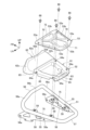
- FIG. 5 is an exploded perspective view of the rear carrier.
- FIG. 6 is a plan view of the rear carrier viewed from above with the top plate not shown.
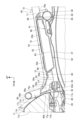
- 7 is a cross-sectional view taken along line VII-VII of FIG. 4.
- FIG. 10 is an enlarged cross-sectional view of the peripheral portion of the vertical wall portion in FIG. 7.
- FIG. 7 is a perspective view of the vehicle body frame.
- FIG. 3 is a left side view of the seat and rear carrier.
- FIG. 4 is a
- the body frame 11 includes a head pipe 18 provided at the front end of the body frame 11 , a front frame 19 positioned behind the head pipe 18 , and a rear frame 20 positioned behind the front frame 19 .
- a front end portion of the front frame 19 is connected to the head pipe 18 .
- Seat 17 is supported by rear frame 20 .
- the front fork 14 is supported by a head pipe 18 so as to be steerable left and right.
- the front wheel 13 is supported by an axle 13 a provided at the lower end of the front fork 14 .
- a steering handle 21 gripped by a passenger is attached to the upper end of the front fork 14 .
- the swing arm 16 is supported by a pivot shaft 22 supported by the vehicle body frame 11 .
- the pivot shaft 22 is a shaft extending horizontally in the vehicle width direction.
- a pivot shaft 22 is inserted through the front end of the swing arm 16 .
- the swing arm 16 swings up and down around the pivot shaft 22 .
- the rear wheel 15 is supported by an axle 15 a provided at the rear end of the swing arm 16 .
- Power unit 12 is arranged between front wheel 13 and rear wheel 15 and supported by body frame 11 .
- Power unit 12 is an internal combustion engine.
- the power unit 12 includes a crankcase 23 and a cylinder portion 24 that houses reciprocating pistons.
- An exhaust device 25 is connected to an exhaust port of the cylinder portion 24 .
- the output of power unit 12 is transmitted to rear wheels 15 by a driving force transmission member that connects power unit 12 and rear wheels 15 .
- the straddle-type vehicle 10 also includes a front fender 26 that covers the front wheels 13 from above, a rear fender 27 that covers the rear wheels 15 from above, a step 28 on which the passenger puts his or her feet, and a fuel for storing the fuel used by the power unit 12. and a tank 29 .
- a front fender 26 is attached to the front fork 14 .
- the rear fender 27 and step 28 are provided below the seat 17 .
- the fuel tank 29 is supported by the vehicle body frame 11 .
- FIG. 2 is a perspective view of the body frame 11.
- FIG. The straddle-type vehicle 10 is a motorcycle. 1 and 2, the front frame 19 includes a main frame 31 extending rearwardly downward from the head pipe 18, a pair of left and right pivot frames 32 extending downward from the rear end of the main frame 31, and a head pipe. 18 and a pair of left and right lower frames 34 extending rearward from the lower end of the down frame 33 and connected to the lower end of the pivot frame 32 .
- the rear frame 20 includes a pair of left and right seat frames 35 extending rearward from the upper portion of the pivot frame 32 , and a pair of left and right seat frames 35 extending rearward and upward from a position below the seat frame 35 in the pivot frame 32 and connected to the seat frame 35 . and a subframe 36 .
- the rear frame 20 includes a plate-shaped gusset 37 extending downward from the rear portion of the seat frame 35 .
- a rear end portion of the sub-frame 36 is connected to the seat frame 35 via a gusset 37 .
- the rear ends of the left and right seat frames 35 are connected in the vehicle width direction by a rear end connection portion 38 extending in the vehicle width direction (left-right direction).
- the rear portions of the left and right seat frames 35 are connected in the vehicle width direction by a cross member 39 extending in the vehicle width direction in front of the rear end connection portion 38 .
- Pivot shaft 22 is supported by pivot frame 32 .
- the upper end of the rear cushion 41 is connected to the gusset 37 and the lower end of the rear cushion 41 is connected to the rear end of the swing arm 16 .
- the straddle-type vehicle 10 includes a side cover 42 that covers the rear frame 20 from the outside in the vehicle width direction.
- the side cover 42 covers an accessory case (not shown) capable of storing tools and the like from the outside in the vehicle width direction.
- the side cover 42 includes a key cylinder 42a operated by the main key of the straddle-type vehicle 10. As shown in FIG. When the lock by the key cylinder 42a is released, the side cover 42 can be opened, and the passenger can access the accessory compartment.
- the saddle-ride type vehicle 10 includes a center stand 45 that supports the saddle-ride type vehicle 10 in an upright state when parked.
- the saddle-ride type vehicle 10 has a rear carrier 50 on which luggage can be loaded behind the seat 17. - ⁇ The rear carrier 50 is attached to the rear frame 20 .
- the rear carrier 50 is arranged above the rear frame 20 and the rear fender 27 .
- the seat 17 is a single seat. Instead of the seat 17 and the rear carrier 50 , it is also possible to attach a two-seater seat extending rearward from the seat 17 to the rear frame 20 .
- the rear carrier 50 includes a carrier body 51 provided behind the seat 17, a storage box 52 attached to the carrier body, and a top plate 53 covering the storage box 52 from above.
- FIG. 6 is a plan view of the rear carrier 50 viewed from above with the top plate 53 not shown.
- the carrier body 51 includes a pair of left and right carrier frames 55 extending in the longitudinal direction of the vehicle, a front frame portion 56 connecting the front ends of the left and right carrier frames to the left and right, and a rear portion of the left and right carrier frames. and a rear frame portion 57 connecting the ends to the left and right.
- the carrier main body 51 is formed in a substantially rectangular closed loop shape in plan view by left and right carrier frames 55 , a front frame portion 56 and a rear frame portion 57 .
- the carrier frame 55, the front frame portion 56, and the rear frame portion 57 are pipe materials.
- the left and right carrier frames 55 extend rearward so that the distance between them decreases toward the rear.
- the front frame portion 56 is laterally longer than the rear frame portion 57 .
- the front frame portion 56 includes an upwardly extending portion 56a extending inwardly and upwardly in the vehicle width direction from the front end of each carrier frame 55, and left and right connecting portions 56b connecting the upper ends of the left and right upwardly extending portions 56a to the left and right.
- the front frame portion 56 obliquely extends forward and upward when viewed from the side of the vehicle.
- the carrier body 51 also includes side walls 58 extending downward from each carrier frame 55 .
- the side wall portion 58 extends downward from the inner surface of the carrier frame 55 in the vehicle width direction.
- the side wall portion 58 is a plate member elongated in the vehicle front-rear direction.
- the side wall portion 58 is provided with a plurality of fixing holes 58a arranged side by side in the front-rear direction.
- the carrier main body 51 includes a plurality of stay portions 59 extending inward in the vehicle width direction from the upper portion of the side wall portion 58 .
- one stay portion 59 is provided on the front side of the carrier frame 55 and one stay portion 59 is provided on the rear side of the carrier frame 55 in each side wall portion 58 .
- the stay portion 59 is provided at a position overlapping the carrier frame 55 in a vehicle side view.
- the carrier main body 51 is made of, for example, a metal material such as an iron-based material or a light metal alloy.
- the carrier main body 51 is set so that the left and right side wall portions 58 are in contact with the outer side surfaces of the rear portion of the rear frame 20 from outside in the vehicle width direction.
- the carrier main body 51 is fixed to the rear frame 20 by carrier fasteners 60 that are inserted through the fixing holes 58 a of the side wall portion 58 from the outside in the vehicle width direction. That is, the side wall portion 58 is a stay that fixes the carrier body 51 to the rear frame 20 .
- the carrier frame 55 , the front frame portion 56 and the rear frame portion 57 are positioned above the seat frame 35 . When viewed from the side of the vehicle, the carrier frame 55 extends in the front-rear direction of the vehicle along the seat frame 35 in a downwardly forward posture.
- the left and right carrier frames 55 are positioned outside the left and right seat frames 35 in the vehicle width direction.
- FIG. 7 is a cross-sectional view taken along line VII-VII of FIG. 4.
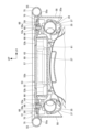
- FIG. FIG. 8 is a cross-sectional view taken along line VIII-VIII of FIG. 3 to 8, the storage box 52 is arranged inside the closed loop-shaped carrier body 51 in plan view. Specifically, the storage box 52 is arranged between the left and right carrier frames 55 in front of the rear frame portion 57 in plan view. Also, in plan view, the front end of the storage box 52 overlaps the front frame portion 56 from below.
- the storage box 52 is formed along the left and right carrier frames 55 in plan view, and the width of the storage box 52 in the vehicle width direction becomes smaller toward the rear.
- the storage box 52 is disposed so as to be inclined forward and downward along the carrier frame 55 when viewed from the side of the vehicle.
- the storage box 52 is arranged above the seat frame 35 and overlaps the seat frame 35 from above.
- the storage box 52 integrally includes a storage portion 61 that opens upward and can store articles, and a vertical wall portion 62 that extends upward from the storage portion 61 in front of the storage portion 61 .
- the storage box 52 is made of, for example, a resin material, and the storage portion 61 and the vertical wall portion 62 are integrally formed by resin molding using a mold.
- the storage portion 61 includes a storage recess 63 that is recessed downward, and a flange portion 64 that extends outward from the periphery of the storage recess 63 in plan view.
- the flange portion 64 is flat.
- the flange portion 64 forms the outer shape of the storage portion 61 in plan view.
- the flange portion 64 extends to both left and right sides, forward, and rearward of the storage recess 63 in a plan view.
- the accommodation recess 63 is a recess recessed downward with respect to the upper surface of the flange portion 64 .
- the storage recess 63 is box-shaped and opens upward.
- the flange portion 64 is provided with a plurality of storage box fixing holes 64a penetrating vertically through the flange portion 64 .
- the storage box fixing hole 64 a is provided at a position overlapping the stay portion 59 of the carrier body 51 .
- the vertical wall portion 62 includes a vertical wall portion rear wall 62a extending forward and upward from the front edge of the flange portion 64, and a vertical wall portion front wall 62b extending downward from the front edge of the vertical wall portion rear wall 62a (the front surface of the storage box). and a pair of left and right vertical wall portion side walls 62c connecting the side edges of the vertical wall portion rear wall 62a and the side edges of the vertical wall portion front wall 62b in the front-rear direction.
- the vertical wall portion 62 extends from near the front end of the left carrier frame 55 to near the front end of the right carrier frame 55 .
- the inside of the vertical wall portion 62 is hollow, and this hollow portion opens downward.
- the storage box 52 includes a plurality of frame contact portions 65 that extend downward and contact the upper surface of the seat frame 35 .
- the frame abutment portions 65 are provided at the lower end portion of the side portion of the vertical wall portion 62 , the side edge portion of the flange portion 64 , and the rear edge portion of the flange portion 64 .
- the storage box 52 has the flange portion 64 placed on the upper surface of the stay portion 59 of the carrier body 51 .
- the storage box 52 is fixed to the carrier body 51 by a storage box fastener 66 that is inserted through the storage box fixing hole 64 a from above and fastened to the stay portion 59 .
- the top plate 53 is arranged between the left and right carrier frames 55 in front of the rear frame portion 57 and covers the storage portion 61 of the storage box 52 from above.
- the top plate 53 is arranged behind the front frame portion 56 and the vertical wall portion 62 .
- the top plate 53 is a substantially rectangular plate material formed so as to follow the outer shape of the storage portion 61 in plan view.
- the top plate 53 covers the storage recess 63 and the flange portion 64 of the storage portion 61 from above.
- the top plate 53 is formed along the left and right carrier frames 55 in plan view, and the width of the top plate 53 in the vehicle width direction becomes smaller toward the rear.
- the top plate 53 is made of, for example, a metallic material such as an iron-based material or a light metal alloy.
- the top plate 53 and the carrier body 51 are made of a material having higher rigidity than the storage box 52 .
- the top plate 53 includes a plurality of top plate fixing holes 53a vertically penetrating the top plate 53 .
- the top plate 53 is arranged so that the lower surface of the top plate 53 contacts the flange portion 64 of the storage box 52 from above.
- the top plate 53 is fastened to the stay portion 59 of the carrier main body 51 by a storage box fastener 66 that is inserted through the top plate fixing hole 53a from above. That is, the top plate 53 is fastened together with the storage box 52 to the stay portion 59 by the storage box fasteners 66 . Therefore, there is no need to fasten the top plate 53 with a dedicated fastener, and the number of parts can be reduced.
- the stay portion 59 is provided with a cylindrical portion 59a (FIG. 8) through which the storage box fastener 66 is inserted.
- the cylindrical portion 59 a protrudes upward from the upper surface of the plate-like portion of the stay portion 59 .
- the inner circumference of the cylindrical portion 59a is provided with a female screw portion into which the storage box fastener 66 is screwed.
- the storage box 52 is positioned by fitting the storage box fixing hole 64a into the cylindrical portion 59a.
- the lower surface of the top plate 53 contacts the upper surface of the cylindrical portion 59a, and the axial force of fastening of the storage box fastener 66 is received by the cylindrical portion 59a.
- the flange portion 64 of the storage box 52 is sandwiched between the lower surface of the top plate 53 and the upper surface of the plate-like portion of the stay portion 59 .
- the upper surface of the top plate 53 is provided with a plurality of protrusions 53b that protrude upward, thereby forming an uneven shape.
- the convex portion 53b is formed by deforming the material of the top plate 53 by pressing so as to bulge upward. This uneven shape increases the rigidity of the top plate 53 .
- FIG. 9 is a cross-sectional view taken along line IX-IX of FIG. 4.
- FIG. 4 and 7 to 9 the storage recess 63 is closed by contact between the lower surface of the peripheral portion of the top plate 53 and the upper surface of the flange portion 64. As shown in FIG. As a result, entry of water adhering to the rear carrier 50 into the storage recess 63 is suppressed.
- the storage recess 63 is arranged between the left and right seat frames 35 and extends below the upper surfaces of the left and right seat frames 35 .
- a laterally extending portion 70 (extending portion) is provided.
- the side extending portion 70 extends outward in the vehicle width direction with respect to the contact portion 68 and is bent downward toward the outside in the vehicle width direction.
- the side extending portion 70 is formed by bending the side edge portion of the top plate 53 downward. Since the side extending portion 70 bends downward, it effectively improves the waterproofness of the storage recess 63 .
- a labyrinth structure is formed by the abutting portion 68 and the laterally extending portion 70 . Therefore, the entry of water adhering to the rear carrier 50 into the storage recess 63 is suppressed.
- An extension portion 71 (extension portion) is provided.
- the rear extending portion 71 extends rearward with respect to the contact portion 68 and is bent so as to be positioned downward toward the rear.
- the rear extension portion 71 is formed by bending the rear edge portion of the top plate 53 downward. Since the rear extension part 71 bends downward, it effectively improves the waterproofness of the storage recess 63 .
- a labyrinth structure is formed by the contact portion 68 and the rearwardly extending portion 71 . Therefore, the entry of water adhering to the rear carrier 50 into the storage recess 63 is suppressed.
- the front edge portion of the top plate 53 is an inclined portion 72 that is inclined forward and downward when viewed from the side of the vehicle.
- the lower surface of the inclined portion 72 contacts the upper surface 64 b of the front edge portion of the flange portion 64 .
- the upper surface 64b is inclined forward and downward when viewed from the side of the vehicle. That is, the portion where the lower surface of the inclined portion 72 and the upper surface 64b abut is inclined so as to rise toward the storage recessed portion 63 in the rear. Therefore, water is prevented from entering the storage recess 63 through the contact portion between the lower surface of the inclined portion 72 and the upper surface 64b.
- the side wall portion 58 of the carrier body 51 covers the storage portion 61 and the top plate 53 from the outside in the vehicle width direction. Specifically, the side wall portion 58 covers the contact portion 68 and the side extending portion 70 of the side edge portion of the top plate 53 from the outside in the vehicle width direction. Therefore, the side wall portion 58 can prevent water from adhering to the top plate 53 and the storage portion 61 from the outside, and the waterproofness of the storage portion 61 can be improved. Moreover, since the side wall portion 58 is a stay that fixes the carrier main body 51 to the rear frame 20, it is possible to improve waterproofness with a simple structure using a stay.
- An article 69 (FIG. 8) can be stored in the storage recess 63 .
- the article 69 is, for example, parts such as a vehicle-mounted device of an electronic toll collection system for toll roads, and vehicle-mounted tools.
- an occupant operates the key cylinder 42a (FIG. 1) with the above-described main key to open the side cover 42 and take out the tools stored in the accessory case. The occupant uses this tool to release the fastening of the storage box fasteners 66 and then removes the top plate 53 to access the storage recess 63 .
- the upper surfaces of the left and right carrier frames 55 are loading surfaces 75 on which cargo 73 is loaded.
- the loading surface 75 is inclined forward and downward when viewed from the side of the vehicle. If the cargo 73 is larger than the space between the left and right carrier frames 55 and is difficult to deform like a box, the cargo 73 is placed on the loading surfaces 75 of both the left and right carrier frames 55 .
- the luggage 73 is fixed to the rear carrier 50 by a fixing tool such as a string or a net.
- the top plate 53 is substantially parallel to the loading surface 75 when viewed from the side of the vehicle, and is arranged in a downwardly forward posture.
- the upper surface of the top plate 53 is arranged below the loading surface 75 and above the lower surfaces 55 a of the left and right carrier frames 55 when viewed from the side of the vehicle. Therefore, when viewed from the side of the vehicle, the top plate 53 overlaps the carrier frame 55 from the inside in the vehicle width direction, and is not visible when viewed from the side of the vehicle.
- the upper surface of the storage portion 61 is also arranged below the loading surface 75 and above the lower surfaces 55 a of the left and right carrier frames 55 when viewed from the side of the vehicle.
- the top plate 53 is positioned below the loading surface 75 and does not protrude upward from the loading surface 75 . Therefore, the top plate 53 is prevented from becoming an obstacle to the load 73 , and the large load 73 can be favorably supported by the left and right loading surfaces 75 . If the load 73 is easily deformable, such as a bag, the load 73 protrudes below the loading surface 75 between the left and right loading surfaces 75 due to deformation due to gravity. 53. Since the top plate 53 is arranged above the lower surface 55a of the carrier frame 55 and is positioned close to the loading surface 75, it can support easily deformable loads such as bags.
- the load 73 can be loaded on the top board 53 .
- the storage box fasteners 66 are positioned below the loading surface 75 . For this reason, the storage box fastener 66 is prevented from interfering with the load 73 , and the large load 73 can be favorably supported by the left and right loading surfaces 75 .
- a vertical wall portion 62 of the storage box 52 extends above the loading surface 75 in front of the top plate 53 and the storage portion 61 . Specifically, the vertical wall portion 62 extends upward from an extension line 75a that extends the loading surface 75 forward. The vertical wall portion 62 extends upward between the load surface 75 and the load 73 loaded on the top plate 53 and the seat rear surface 17d, and suppresses the load 73 from contacting the seat rear surface 17d. As a result, even if the load 73 moves forward or is long in the longitudinal direction, the contact between the load 73 and the seat rear surface 17d can be suppressed, and the occurrence of scratches on the seat rear surface 17d can be suppressed. can.
- the cross member 39 of the rear frame 20 is provided with a seat stay 43 to which the rear end portion of the seat 17 is fixed.
- the seat stay 43 extends rearward and upward from the upper surface of the cross member 39 .
- the seat 17 has a mounting portion 17e extending from the lower surface of the rear portion of the seat 17 to the rear of the seat rear surface 17d.
- the mounting portion 17e is fixed to the seat stay 43 by a seat fastener 17f inserted through the mounting portion 17e from above.
- the seat fastener 17f is positioned above the rear fender 27, and is positioned between the left and right carrier frames 55 and behind the front frame portion 56 in plan view.
- the vertical wall portion 62 of the storage box 52 covers the sheet fastener 17f and the mounting portion 17e from above. Thereby, the sheet fastener 17f and the mounting portion 17e can be hidden by the vertical wall portion 62, and the appearance is good.
- FIG. 10 is an enlarged cross-sectional view of the peripheral portion of the vertical wall portion 62 in FIG. 4, 7, and 10, the seat rear surface 17d is a rearwardly downward inclined surface as viewed from the side of the vehicle. Further, the seat rear surface 17d is a curved surface that is convex rearward in plan view.
- the front frame portion 56 of the carrier body 51 and the vertical wall portion 62 of the storage box 52 are arranged so as to approach the seat rear surface 17d from behind.
- the vertical wall portion 62 is positioned behind the lower portion of the seat rear surface 17d below the left and right connecting portions 56b, and overlaps the lower portion of the seat rear surface 17d from behind when viewed from the rear of the vehicle.
- the vertical wall portion front wall 62b faces the seat rear surface 17d from behind.
- the vertical wall portion front wall 62 b forms the front surface of the storage box 52 .
- the vertical wall portion front wall 62b is inclined rearwardly downward along the seat rear surface 17d. Further, the vertical wall portion front wall 62b is curved so as to be concave rearward along the seat rear surface 17d in a plan view.
- a distance L1 between the vertical wall portion front wall 62b and the seat rear surface 17d is smaller than a distance L2 between the left and right connecting portions 56b of the front frame portion 56 and the seat rear surface 17d.
- the area where the vertical wall portion front wall 62b overlaps with the seat rear surface 17d is the area where the left and right connecting portions 56b overlap with the seat rear surface 17d. bigger than For example, when the seat 17 is deformed by an occupant sitting on the seat 17, the seat rear surface 17d is displaced rearward.
- the distance L1 is smaller than the distance L2, so when the seat rear surface 17d is displaced rearward, the seat rear surface 17d contacts the vertical wall portion front wall 62b before the left and right connecting portions 56b. Therefore, the left-right connection portion 56b is prevented from strongly contacting the seat rear surface 17d, and the occurrence of scratches on the seat rear surface 17d and the left-right connection portion 56b can be suppressed. Since the vertical wall portion front wall 62b is located in a complicated place below the left and right connecting portions 56b, it is difficult to be visually recognized from the outside. On the other hand, since the left and right connection portions 56b are exposed to the outside, for example, if the coating of the left and right connection portions 56b is damaged, the damage is likely to be conspicuous.
- the distance L1 increases downward at the lower portion of the vertical wall portion front wall 62b. Accordingly, the distance D1 between the lower end 62d of the vertical wall portion front wall 62b and the seat rear surface 17d is larger than the distance D2 between the portion of the vertical wall portion front wall 62b above the lower end 62d and the seat rear surface 17d. Therefore, the lower end 62d of the vertical wall portion front wall 62b is prevented from coming into contact with the seat rear surface 17d, and the occurrence of scratches on the seat rear surface 17d can be suppressed. Further, the lower end 62d of the vertical wall portion front wall 62b is located below the lower end 17g of the seat rear surface 17d. Therefore, the lower end 62d of the vertical wall portion front wall 62b is prevented from coming into contact with the seat rear surface 17d, and the occurrence of scratches on the seat rear surface 17d can be suppressed.
- the distance L2 between the left-right connecting portion 56b and the seat rear surface 17d is ensured to be large, the occupant or the like can easily put their hands between the left-right connecting portion 56b and the seat rear surface 17d and easily grip the left-right connecting portion 56b.
- the upper surface of the left-right connecting portion 56b is located below the upper surface 17h of the rear end portion of the seat 17. As shown in FIG. Therefore, it is possible to secure a distance between the occupant seated on the seat 17 and the upper surface of the left-right connection portion 56b, thereby suppressing the contact of the occupant seated on the seat 17 with the left-right connection portion 56b.
- the rear portion 20a of the rear frame 20 extends rearward from the seat 17.
- the rear portion 20 a is formed by the rear portion of the seat frame 35 and the rear end connection portion 38 .
- the storage box 52 abuts on the upper surface of the rear portion 20a via the frame abutting portion 65.
- the frame abutting portion 65 may be close to the upper surface of the rear portion 20a during normal times when the load 73 or the like is not loaded. In this case, when a predetermined load acts on the top plate 53, the storage box 52 bends downward and the frame contact portion 65 contacts the upper surface of the rear portion 20a.
- the rear carrier 50 is attached to the carrier main body 51 provided behind the passenger seat 17 of the saddle type vehicle 10 and the carrier main body 51.
- the carrier body 51 includes at least a pair of left and right carrier frames 55 extending in the vehicle front-rear direction.
- the storage box 52 is arranged between the left and right carrier frames 55, and is arranged upward. It has a storage section 61 that opens to store articles 69 and a vertical wall section 62 that extends upward from the storage section 61 in front of the storage section 61 .
- the storage portion 61 is arranged below a loading surface 75 that is the upper surface of the carrier frame 55 , and the vertical wall portion 62 extends above the loading surface 75 .
- the article 69 can be stored in the storage portion 61, and the storage box 52 includes the vertical wall portion 62 extending upward from the loading surface 75 in front of the storage portion 61.
- the vertical wall portion 62 can prevent the cargo 73 from contacting the seat 17 . Therefore, by using the vertical wall portion 62 of the storage box 52 , contact of the load 73 with the seat 17 can be suppressed with a simple structure, and the seat 17 can be protected from the load 73 .
- a top plate 53 that covers the storage portion 61 from above is arranged between the left and right carrier frames 55 .
- the vertical wall portion 62 is positioned in front of the top plate 53 .
- the article 69 can be stored in the storage section 61 satisfactorily.
- the top plate 53 is positioned below the loading surface 75 , the load 73 can be well supported by the loading surface 75 .
- the vertical wall portion 62 can effectively prevent the cargo extending forward from the top plate 53 from contacting the seat 17 .
- the top plate 53 is fastened to the carrier main body 51 . According to this configuration, the top plate 53 is fastened to the carrier main body 51 and firmly supported, so that the load 73 positioned below the loading surface 75 can be well supported by the top plate 53 .
- the top plate 53 has a laterally extending portion 70 and a rear extending portion extending outward from the storage portion 61 with respect to an abutment portion 68 where the lower surface of the top plate 53 and the storage portion 61 abut in plan view. 71 , the laterally extending portion 70 and the rearwardly extending portion 71 are bent downward with respect to the abutment portion 68 . According to this configuration, the laterally extending portion 70 and the rearwardly extending portion 71 of the top plate 53 are bent downward with respect to the contact portion 68 where the lower surface of the top plate 53 and the storage portion 61 contact each other.
- a labyrinth shape can be provided by the laterally extending portion 70 and the rearwardly extending portion 71, and the waterproofness of the storage portion 61 can be improved.
- a front edge portion of the top plate 53 is an inclined portion 72 that is inclined forward and downward when viewed from the side of the vehicle, and a lower surface of the inclined portion 72 contacts the storage portion 61 .
- the lower surface of the inclined portion 72 which is inclined forward downward, abuts against the storage portion 61, so that water enters between the lower surface of the inclined portion 72 and the storage portion 61. becomes difficult. Therefore, the waterproofness of the storage portion 61 can be improved.
- the upper surface of the top plate 53 is formed with an uneven shape. According to this configuration, the rigidity of the top plate 53 can be increased by the uneven shape, so that the load 73 can be well supported by the top plate 53 .
- the carrier body 51 includes a side wall portion 58 extending downward from the carrier frame 55, and the side wall portion 58 covers the storage portion 61 from the outside. According to this configuration, the side wall portion 58 that covers the storage portion 61 from the outside can improve the waterproofness of the storage portion 61 .
- the carrier main body 51 also includes a front frame portion 56 that connects the left and right carrier frames 55 to the left and right.
- the wall portion front wall 62b faces the seat rear surface 17d from the rear below the front frame portion 56, and the distance L1 between the vertical wall portion front wall 62b and the seat rear surface 17d is the distance between the front frame portion 56 and the seat rear surface 17d. smaller than L2. According to this configuration, since the distance L1 is smaller than the distance L2, when the seat 17 is largely deformed due to the seating of the occupant, the seat rear surface 17d is moved to the front wall of the vertical wall portion before the front frame portion 56. 62b.
- the front frame portion 56 is positioned below the upper surface 17h of the rear end portion of the seat 17 . According to this configuration, when an occupant is seated on the seat 17, the distance between the occupant and the front frame portion 56 can be secured, and the front frame portion 56 can be prevented from interfering with the occupant.
- the saddle-ride type vehicle 10 also includes a rear frame 20 that supports the seat 17, the rear portion 20a of the rear frame 20 extending rearwardly of the seat 17, and the storage box 52 hitting the rear portion 20a of the rear frame 20 from above.
- a frame abutting portion 65 is provided. According to this configuration, the storage box 52 contacts the rear portion 20 a of the rear frame 20 from above via the frame contact portion 65 , so that the rear frame 20 can receive the load that the storage box 52 receives from the luggage 73 . . Therefore, the luggage 73 can be well supported by the rear carrier 50 .
- the above-described embodiment shows one mode to which the present invention is applied, and the present invention is not limited to the above-described embodiment.
- the carrier main body 51 has been described as including the left and right carrier frames 55, the front frame portion 56, and the rear frame portion 57, but the present invention is not limited to this.
- the carrier main body 51 may be provided with at least a pair of left and right carrier frames 55 .
- the top plate 53 is provided to cover the storage portion 61 from above, but the present invention is not limited to this, and the top plate 53 may be omitted.
- the rear carrier 50 mounted on the saddle-ride type vehicle 10, which is a motorcycle was described as an example, but the present invention is not limited to this, and the rear carrier 50 is It may be provided in a three-wheel saddle-ride type vehicle and a saddle-ride type vehicle having four or more wheels.
- the carrier body includes a pair of left and right carriers extending in the vehicle front-rear direction. At least a carrier frame is provided, and the storage box is arranged between the left and right carrier frames, and the storage box has a storage section that opens upward and can store articles, and a storage section in front of the storage section. and a vertical wall portion extending upward from the carrier frame, wherein the storage portion is disposed below a loading surface that is the top surface of the carrier frame, and the vertical wall portion extends upward from the loading surface.
- a rear carrier characterized by: According to this configuration, articles can be stored in the storage section, and since the storage box includes the vertical wall portion extending upward from the loading surface in front of the storage section, the cargo on the loading surface comes into contact with the sheet. This can be suppressed by the vertical wall portion. Therefore, by using the vertical wall portion of the storage box, the seat can be prevented from coming into contact with the load with a simple structure, and the seat can be protected from the load.
- (Configuration 2) A top plate that covers the storage portion from above is disposed between the left and right carrier frames, and an upper surface of the top plate is positioned below the loading surface, and when viewed from the side of the vehicle, the carrier
- the top plate includes an extension portion extending outward from the storage portion with respect to a contact portion where the lower surface of the top plate and the storage portion abut in plan view, and the extension portion is bent downward with respect to the contact portion. According to this configuration, the extending portion of the top plate is bent downward with respect to the abutment portion where the lower surface of the top plate and the storage portion abut. can improve the waterproofness of
- Configurations 1 to 6 Any one of Configurations 1 to 6, wherein the carrier body includes a side wall portion extending downward from the carrier frame, and the side wall portion covers the storage portion from the outside. rear carrier. According to this configuration, the waterproofness of the storage portion can be improved by the side wall portion that covers the storage portion from the outside.
- the carrier body includes a front frame portion that connects the left and right carrier frames to the left and right, the front frame portion faces the rear surface of the seat from the rear, and the front surface of the storage box extends to the front side. From Configuration 1, wherein the storage box faces the rear surface of the seat from the rear below the frame portion, and the distance between the front surface of the storage box and the rear surface is smaller than the distance between the front frame portion and the rear surface. 8.
- the rear carrier according to any one of 7. According to this configuration, when the seat is largely deformed due to, for example, the occupant sitting on the seat, the rear surface of the seat hits the front surface of the storage box before the front frame portion.
- the front frame portion can be held by inserting a hand between the rear surface of the seat and the front frame portion. is easy to grasp.
- the front frame portion can be pushed by inserting the hand between the rear surface of the seat and the front frame portion. Easy to grip.
- the straddle-type vehicle includes a rear frame that supports the seat, the rear portion of the rear frame extends rearwardly of the seat, and the storage box abuts the rear portion of the rear frame from above.
- the rear carrier according to any one of configurations 1 to 9, further comprising a frame contact portion. According to this configuration, the storage box contacts the rear portion of the rear frame from above via the frame contact portion, so that the rear frame can receive the load that the storage box receives from the luggage. Therefore, luggage can be well supported by the rear carrier.
Landscapes
- Engineering & Computer Science (AREA)
- Mechanical Engineering (AREA)
- Automatic Cycles, And Cycles In General (AREA)
Priority Applications (1)
| Application Number | Priority Date | Filing Date | Title |
|---|---|---|---|
| JP2023557632A JP7607146B2 (ja) | 2021-11-08 | 2022-08-23 | リアキャリア |
Applications Claiming Priority (2)
| Application Number | Priority Date | Filing Date | Title |
|---|---|---|---|
| JP2021-181986 | 2021-11-08 | ||
| JP2021181986 | 2021-11-08 |
Publications (1)
| Publication Number | Publication Date |
|---|---|
| WO2023079816A1 true WO2023079816A1 (ja) | 2023-05-11 |
Family
ID=86241215
Family Applications (1)
| Application Number | Title | Priority Date | Filing Date |
|---|---|---|---|
| PCT/JP2022/031713 Ceased WO2023079816A1 (ja) | 2021-11-08 | 2022-08-23 | リアキャリア |
Country Status (2)
| Country | Link |
|---|---|
| JP (1) | JP7607146B2 (https=) |
| WO (1) | WO2023079816A1 (https=) |
Citations (5)
| Publication number | Priority date | Publication date | Assignee | Title |
|---|---|---|---|---|
| DE3513878A1 (de) * | 1984-10-11 | 1986-04-17 | Henssler, Heinrich, 7070 Schwäbisch Gmünd | Zweirad-gepaecktraeger, insbesondere fahrrad-gepaecktraeger |
| JPH0315288U (https=) * | 1989-06-27 | 1991-02-15 | ||
| DE4331615A1 (de) * | 1992-09-19 | 1994-04-14 | Herbert Prieschl | Gepäckträgereinrichtung für ein Fahrrad |
| JP2008074290A (ja) * | 2006-09-22 | 2008-04-03 | Honda Motor Co Ltd | 車両用通信装置の取付構造 |
| CN202400214U (zh) * | 2011-12-30 | 2012-08-29 | 杨金超 | 一种多功能车载行李架 |
-
2022
- 2022-08-23 JP JP2023557632A patent/JP7607146B2/ja active Active
- 2022-08-23 WO PCT/JP2022/031713 patent/WO2023079816A1/ja not_active Ceased
Patent Citations (5)
| Publication number | Priority date | Publication date | Assignee | Title |
|---|---|---|---|---|
| DE3513878A1 (de) * | 1984-10-11 | 1986-04-17 | Henssler, Heinrich, 7070 Schwäbisch Gmünd | Zweirad-gepaecktraeger, insbesondere fahrrad-gepaecktraeger |
| JPH0315288U (https=) * | 1989-06-27 | 1991-02-15 | ||
| DE4331615A1 (de) * | 1992-09-19 | 1994-04-14 | Herbert Prieschl | Gepäckträgereinrichtung für ein Fahrrad |
| JP2008074290A (ja) * | 2006-09-22 | 2008-04-03 | Honda Motor Co Ltd | 車両用通信装置の取付構造 |
| CN202400214U (zh) * | 2011-12-30 | 2012-08-29 | 杨金超 | 一种多功能车载行李架 |
Also Published As
| Publication number | Publication date |
|---|---|
| JP7607146B2 (ja) | 2024-12-26 |
| JPWO2023079816A1 (https=) | 2023-05-11 |
Similar Documents
| Publication | Publication Date | Title |
|---|---|---|
| US6499784B2 (en) | Article storage device of motorcycle | |
| JP5131470B2 (ja) | 自動二輪車 | |
| JP2002225765A (ja) | 自動二輪車の収納ボックス構造 | |
| JP5113358B2 (ja) | 鞍乗型車両 | |
| CA2723969C (en) | Vehicle having a removable sub-pipe | |
| JP2002284064A (ja) | 車両の物品収納部構造 | |
| JP2005096546A (ja) | 車両の工具収納構造 | |
| JP5310042B2 (ja) | 自動二輪車の物品収納構造 | |
| CN103303407B (zh) | 机动二轮车 | |
| JP7607146B2 (ja) | リアキャリア | |
| JP5465643B2 (ja) | 鞍乗り型車両 | |
| JP3674689B2 (ja) | 自動二輪車 | |
| JP4546204B2 (ja) | グラブレール | |
| JP2013129344A (ja) | 鞍乗型電動車両 | |
| JP7607147B2 (ja) | 収納部構造 | |
| JP3470575B2 (ja) | 自動二輪車の収納箱内工具収納装置 | |
| JPH09301247A (ja) | スクータ型車両におけるリヤカバー取付構造 | |
| JPH0216948Y2 (https=) | ||
| JP7427701B2 (ja) | シートカウル固定構造 | |
| CN223764613U (zh) | 跨骑型车辆 | |
| JP3367760B2 (ja) | 車両の車体構造 | |
| JP3311400B2 (ja) | 自動二輪車のキャリア装置 | |
| JP7375162B2 (ja) | 車両 | |
| JP7671810B2 (ja) | 鞍乗り型車両 | |
| JP3470700B2 (ja) | スクータ型自動二輪車の収納装置 |
Legal Events
| Date | Code | Title | Description |
|---|---|---|---|
| 121 | Ep: the epo has been informed by wipo that ep was designated in this application |
Ref document number: 22889641 Country of ref document: EP Kind code of ref document: A1 |
|
| ENP | Entry into the national phase |
Ref document number: 2023557632 Country of ref document: JP Kind code of ref document: A |
|
| WWE | Wipo information: entry into national phase |
Ref document number: 202417040996 Country of ref document: IN |
|
| 122 | Ep: pct application non-entry in european phase |
Ref document number: 22889641 Country of ref document: EP Kind code of ref document: A1 |