WO2023079637A1 - 車両用冷凍サイクルユニット、及び車両用空調装置 - Google Patents
車両用冷凍サイクルユニット、及び車両用空調装置 Download PDFInfo
- Publication number
- WO2023079637A1 WO2023079637A1 PCT/JP2021/040610 JP2021040610W WO2023079637A1 WO 2023079637 A1 WO2023079637 A1 WO 2023079637A1 JP 2021040610 W JP2021040610 W JP 2021040610W WO 2023079637 A1 WO2023079637 A1 WO 2023079637A1
- Authority
- WO
- WIPO (PCT)
- Prior art keywords
- compressor
- evaporator
- condenser
- vehicle
- refrigeration cycle
- Prior art date
Links
Images


Classifications
-
- B—PERFORMING OPERATIONS; TRANSPORTING
- B60—VEHICLES IN GENERAL
- B60H—ARRANGEMENTS OF HEATING, COOLING, VENTILATING OR OTHER AIR-TREATING DEVICES SPECIALLY ADAPTED FOR PASSENGER OR GOODS SPACES OF VEHICLES
- B60H1/00—Heating, cooling or ventilating [HVAC] devices
-
- B—PERFORMING OPERATIONS; TRANSPORTING
- B60—VEHICLES IN GENERAL
- B60H—ARRANGEMENTS OF HEATING, COOLING, VENTILATING OR OTHER AIR-TREATING DEVICES SPECIALLY ADAPTED FOR PASSENGER OR GOODS SPACES OF VEHICLES
- B60H1/00—Heating, cooling or ventilating [HVAC] devices
- B60H1/22—Heating, cooling or ventilating [HVAC] devices the heat being derived otherwise than from the propulsion plant
Definitions
- the present disclosure relates to a vehicle refrigeration cycle unit and a vehicle air conditioner.
- Patent Document 1 discloses a refrigeration system that includes a compressor, a heat medium cooler (evaporator), and a heat medium heater (condenser) that are housed in a heat insulating case, and that constitutes a vehicle heat management system. A cycle is disclosed.
- the present disclosure has been made to solve the above problems, and an object of the present disclosure is to provide a vehicle refrigeration cycle unit and a vehicle air conditioner that can suppress a decrease in the heat exchange efficiency of an evaporator. .
- a vehicle refrigeration cycle unit is interposed between a vehicle exterior heat exchanger and a vehicle interior heat exchanger, and A refrigerating cycle unit for a vehicle that exchanges heat between secondary refrigerants that respectively circulate, comprising a refrigerating cycle having a compressor, a condenser, an expansion valve, and an evaporator through which the primary refrigerants sequentially flow, the compressor and the evaporator is longer than the distance between the compressor and the condenser.
- the vehicle refrigeration cycle unit is interposed between the exterior heat exchanger and the interior heat exchanger, and the secondary refrigerant that flows through the exterior heat exchanger and the interior heat exchanger.
- a refrigerating cycle unit for a vehicle that exchanges heat with each other comprising a refrigerating cycle having a compressor, a condenser, an expansion valve, and an evaporator through which a primary refrigerant sequentially flows, and a discharge port of the primary refrigerant in the compressor and the evaporator is longer than the distance between the outlet and the condenser.
- the vehicle refrigeration cycle unit is interposed between the exterior heat exchanger and the interior heat exchanger, and the secondary refrigerant that flows through the exterior heat exchanger and the interior heat exchanger.
- a refrigerating cycle unit for a vehicle that exchanges heat with each other comprising a refrigerating cycle having a compressor, a condenser, an expansion valve, and an evaporator through which a primary refrigerant sequentially flows, and the compressor and the evaporator are connected
- the length of the pipe connecting the compressor and the condenser is longer than the length of the pipe connecting the compressor and the condenser.
- a vehicle air conditioner includes the vehicle refrigeration cycle unit, the vehicle exterior heat exchanger, and the vehicle interior heat exchanger.
- FIG. 1 is a system diagram showing the configuration of a vehicle air conditioner (during heating operation) according to an embodiment
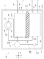
- FIG. 1 is a plan view of a vehicle refrigeration cycle unit according to a first embodiment
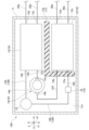
- FIG. It is a top view of the refrigerating-cycle unit for vehicles which concerns on 2nd embodiment.
- FIG. 7 is a plan view of a vehicle refrigeration cycle unit according to a third embodiment; It is a top view of the refrigerating-cycle unit for vehicles which concerns on 4th embodiment.
- 1 is a system diagram showing a configuration of a vehicle air conditioner (during cooling operation) according to an embodiment
- FIG. FIG. 5 is a plan view of a vehicle refrigeration cycle unit according to another embodiment;
- a vehicle air conditioner is a device mounted in an electric vehicle or the like, and conditions the air inside the vehicle. This vehicle air conditioner adjusts the temperature difference between the inside and outside of the vehicle body. In the present embodiment, a configuration in which the vehicle air conditioner performs heating operation will be described as an example.
- the vehicle air conditioner 1 includes a vehicle refrigeration cycle unit 100 , a vehicle interior heat medium circuit 20 , and a vehicle exterior heat medium circuit 30 .
- the lines in an open state through which the refrigerant can flow are indicated by solid lines.
- lines in a closed state in which the refrigerant cannot flow are indicated by dashed lines.
- black coating indicates a closed state
- white coating indicates an open state.
- the vehicle refrigerating cycle unit 100 is a device that circulates a primary refrigerant for exchanging heat with a secondary refrigerant used for air conditioning in the vehicle.
- a primary refrigerant in this embodiment for example, R290 refrigerant (propane), which is a highly flammable hydrocarbon, is adopted.
- the vehicle refrigeration cycle unit 100 includes a casing 11, a refrigeration cycle 10, various lines (a suction line 124, a discharge line 143, a pre-expansion line 136, and a post-expansion line 162), and a partition wall. 17 and.
- the casing 11 has a box-like shape and accommodates the refrigeration cycle 10 , the partition wall portion 17 , the suction line 124 , the discharge line 143 , the pre-expansion line 136 and the post-expansion line 162 inside.
- a refrigerating cycle 10 is composed of a plurality of devices that realize a thermodynamic cycle.
- the refrigerating cycle 10 repeatedly compresses, expands, evaporates, and condenses the primary refrigerant in order to exchange heat between the primary refrigerant as a heat medium and the secondary refrigerant, while sequentially circulating and circulating through a plurality of devices. circuit.
- the refrigeration cycle 10 has an evaporator 12 , a compressor 14 , a condenser 13 , a receiver 15 and an expansion valve 16 .
- the evaporator 12 is a plate-type evaporator that evaporates (vaporizes) the primary refrigerant by exchanging heat between the primary refrigerant that sequentially flows through the refrigeration cycle 10 and the secondary refrigerant that is introduced from the outside of the vehicle refrigeration cycle unit 100.
- a heat exchanger The primary refrigerant inside the evaporator 12 absorbs heat from the secondary refrigerant and cools the secondary refrigerant.
- the evaporator 12 is provided on the bottom surface 11 a of the casing 11 inside the casing 11 .
- the compressor 14 is a device that absorbs heat and compresses the vaporized primary refrigerant through the evaporator 12 .
- Compressor 14 and evaporator 12 are connected by suction line 124 . That is, one end of the suction line 124 is connected to the primary refrigerant outlet portion 12b of the evaporator 12, and the other end of the suction line 124 is connected to the suction port 14b of the compressor .
- the pressure of the primary refrigerant introduced into the compressor 14 is increased by compression of the compressor 14 to a predetermined pressure higher than before compression. This causes the temperature of the primary refrigerant to rise above that before compression.
- the compressor 14 has a compressor casing 14a, a suction port 14b, and a discharge port 14c.
- the compressor casing 14a has a cylindrical shape and is arranged to extend in the gravity direction G from the bottom surface 11a of the casing 11 inside the casing 11 .
- the compressor 14 in this embodiment is a so-called vertical compressor.
- a refrigerant compression mechanism is formed inside the compressor casing 14a.
- the suction port 14b is a refrigerant inlet for introducing refrigerant into the compressor casing 14a.
- the suction port 14b is provided at the end of the compressor casing 14a on the lower side in the direction of gravity G. As shown in FIG. The primary refrigerant is introduced into the compressor casing 14a through this suction port 14b.
- the discharge port 14c is a refrigerant outlet for discharging refrigerant from the compressor casing 14a.
- the discharge port 14c is provided at an upper end in the direction of gravity G in the compressor casing 14a.
- the primary refrigerant is discharged to the outside of the compressor casing 14a through this discharge port 14c.
- the discharge port 14c is the portion of the compressor 14 where the temperature is the highest.
- the condenser 13 exchanges heat between the primary refrigerant, which has a higher temperature and pressure than before being compressed by passing through the compressor 14, and the secondary refrigerant introduced from the outside of the vehicle refrigeration cycle unit 100.
- a plate heat exchanger that condenses (liquefies) the primary refrigerant.
- the condenser 13 is provided on the bottom surface 11 a of the casing 11 inside the casing 11 .
- the condenser 13 and the compressor 14 are connected by a discharge line 143. That is, one end of the discharge line 143 is connected to the discharge port 14 c of the compressor 14 , and the other end of the discharge line 143 is connected to the primary refrigerant inlet 13 a of the condenser 13 .
- the primary refrigerant inside the condenser 13 is cooled by the secondary refrigerant and at the same time increases the temperature of the secondary refrigerant.
- the gaseous primary refrigerant introduced into the condenser 13 is cooled by the secondary refrigerant and transitions to a liquid state after passing through a two-phase state of gas-liquid mixture. Therefore, the primary refrigerant that has passed through the condenser 13 becomes a liquid-mixed fluid.
- the condenser 13 is arranged inside the casing 11 so as to be adjacent to the compressor 14 .
- the direction in which the condenser 13 is adjacent to the compressor 14 (horizontal direction in FIG. 2) is referred to as the first adjacent direction H1
- the direction perpendicular to the first adjacent direction H1 (vertical direction in FIG. 2). direction) is referred to as a second adjacent direction H2.
- the first adjacent direction H1 and the second adjacent direction H2 are orthogonal to the direction of gravity G. As shown in FIG. Therefore, the horizontal direction is defined by the first adjacent direction H1 and the second adjacent direction H2.
- the evaporator 12 is adjacent to the condenser 13 from one side in the second adjacent direction H2. While the condenser 13 is adjacent to the compressor 14 in the first adjacent direction H1, the evaporator 12 is only horizontally spaced from the compressor 14 and is in the first adjacent direction H1 and the second It is not adjacent to the compressor 14 in either of the two adjacent directions H2. Therefore, the distance between compressor 14 and evaporator 12 is longer than the distance between compressor 14 and condenser 13 .
- the discharge port 14c of the compressor 14 in this embodiment faces the condenser 13 in the first adjacent direction H1. Therefore, the distance between the primary refrigerant discharge port 14 c and the evaporator 12 in the compressor 14 is longer than the distance between the discharge port 14 c and the condenser 13 . More specifically, the length of the pipe connecting the compressor 14 and the evaporator 12, namely the suction line 124, is longer than the length of the pipe connecting the compressor 14 and the condenser 13, namely the discharge line 143.
- adjacent in the first adjacent direction H1 means that, of two objects arranged side by side inside the casing 11, more than half the dimension of one in the second adjacent direction H2 is the same as that of the other. It means that the dimension in the second adjacent direction H2 overlaps with the dimension in the first adjacent direction H1.
- adjacent in the second adjacent direction H2 means that, of two objects arranged side by side inside the casing 11, more than half of the dimension of one in the first adjacent direction H1 is the same as the other. It means that the dimension in the first adjacent direction H1 overlaps with the dimension in the second adjacent direction H2.
- the receiver 15 receives the primary refrigerant that has become a gas-liquid mixed fluid by passing through the condenser 13, separates the primary refrigerant into a gas phase and a liquid phase, and temporarily holds them inside. It is a gas-liquid separator.
- the receiver 15 is provided on the bottom surface 11 a of the casing 11 inside the casing 11 .
- the receiver 15 and the condenser 13 are connected by the first line 135 of the pre-expansion line 136 . That is, one end of the first line 135 is connected to the primary refrigerant outlet portion 13 b of the condenser 13 , and the other end of the first line 135 is connected to the refrigerant inlet portion of the receiver 15 .
- the gas-liquid mixed primary refrigerant introduced into the receiver 15 flows into the liquid phase portion stored inside the receiver 15 .
- the liquid portion of the inflowing primary refrigerant is added to the liquid phase, and the remaining gas portion forms bubbles that move upward inside the receiver 15 and are added to the gas phase.
- the primary refrigerant stored as a liquid phase inside the receiver 15 is discharged outside the receiver 15 . As a result, the primary refrigerant in a liquid state is always provided from the receiver 15 .
- the expansion valve 16 is a device that receives the primary refrigerant in a liquid state through the receiver 15 and adiabatically expands the primary refrigerant.
- the expansion valve 16 is provided on the bottom surface 11 a of the casing 11 inside the casing 11 .
- the expansion valve 16 and the receiver 15 are connected by the second line 156 of the pre-expansion line 136 . That is, one end of the second line 156 is connected to the refrigerant outlet of the receiver 15 and the other end of the second line 156 is connected to the expansion valve 16 .
- the pressure of the primary refrigerant introduced into the expansion valve 16 is lowered to a predetermined pressure lower than before expansion due to the expansion action of the expansion valve 16 . This causes the temperature of the primary refrigerant to drop below that before expansion. Specifically, the primary refrigerant that has passed through the expansion valve 16 becomes a fluid in a liquid state, and is lowered to a temperature lower than the temperature of the secondary refrigerant that is a heat exchange destination.
- the expansion valve 16 and the evaporator 12 are connected by a post-expansion line 162 , and the primary refrigerant that has passed through the expansion valve 16 is introduced into the evaporator 12 through this post-expansion line 162 . That is, one end of the post-expansion line 162 is connected to the expansion valve 16 , and the other end of the post-expansion line 162 is connected to the primary refrigerant inlet portion 12 a of the evaporator 12 .
- the partition wall portion 17 is a heat insulating material provided between the evaporator 12 and the condenser 13 inside the casing 11 .
- the thermal conductivity of the partition 17 is lower than that of the casing 11 .
- the partition wall portion 17 in the present embodiment is a partition plate which is a plate member that stands up from the bottom surface 11a of the casing 11 inside the casing 11 toward the upper side in the direction of gravity G and separates the evaporator 12 and the condenser 13. 17a. That is, the longitudinal direction of the partition plate 17a coincides with the first adjacent direction H1. This suppresses heat transfer through the air between the evaporator 12 and the condenser 13 .
- the partition plate 17a provided on the bottom surface 11a between the evaporator 12 and the condenser 13
- heat conduction through the bottom portion of the casing 11 that constitutes the bottom surface 11a is achieved.
- Air convection and heat radiation from the condenser 13 to the evaporator 12 are suppressed.
- these heat conduction, convection, and heat radiation are collectively referred to as "heat transfer.”
- Rubber, resin, or the like, for example, is employed as a material for forming the partition plate 17a.
- the partition plate 17 may be made of the same material as the casing 11 .
- the vehicle-side heat medium circuit 20 is a refrigerant circuit for circulating the secondary refrigerant heat-exchanged with the primary refrigerant in the refrigerating cycle 10 and for conditioning the air inside the vehicle.
- Antifreeze liquid such as ethylene glycol is employed as a coolant liquid (cooling water), for example, as the secondary refrigerant in the present embodiment.
- the vehicle-inside heat medium circuit 20 includes a heater core 21 a (vehicle interior heat exchanger 21 ), a cooler core 21 b (vehicle interior heat exchanger 21 ), a first pump 22 , and a first valve 23 . , a second valve 24, and various lines (first heating medium line 20a to seventh heating medium line 20g).
- the heater core 21a and the cooler core 21b are heat exchangers for exchanging heat between the indoor air inside the vehicle body C, the outdoor air outside the vehicle body C, and the secondary refrigerant.
- Secondary refrigerant that has passed through the condenser 13 of the vehicle refrigeration cycle unit 100 is introduced into the heater core 21a.
- the secondary refrigerant passes through the first pump 22 and the first valve 23 during the process of introducing the secondary refrigerant from the condenser 13 to the heater core 21a.
- the first pump 22 is a pump that pumps the secondary refrigerant that has passed through the condenser 13 to the heater core 21a.
- a first heat medium line 20a as a flow path for sucking the secondary refrigerant into the first pump 22 connects the condenser 13 and the first pump 22 . That is, one end of the first heat medium line 20a is connected to the secondary refrigerant outlet 13d of the condenser 13, and the other end of the first heat medium line 20a is connected to the refrigerant suction port of the first pump 22. ing.
- a second heat medium line 20b as a flow path for discharging the secondary refrigerant from the first pump 22 toward the heater core 21a connects the first pump 22 and the first valve 23 . That is, one end of the second heat medium line 20b is connected to the refrigerant discharge port of the first pump 22, and the other end of the second heat medium line 20b is connected to the first valve .
- the first valve 23 is a three-way valve that can change the flow path (destination) of the secondary refrigerant.
- the first valve 23 and the heater core 21a are connected by a third heat medium line 20c. That is, one end of the third heat medium line 20c is connected to the first valve 23, and the other end of the third heat medium line 20c is connected to the heater core 21a.
- the secondary refrigerant introduced into the heater core 21a is cooled by exchanging heat with the indoor air and the outdoor air introduced into the vehicle body C, and at the same time, raises the temperature of the indoor air and the outdoor air.
- the air in the vehicle body C can be warmed by this.
- the outside air is, for example, the outside air outside the vehicle body C introduced by a blower (not shown) arranged upstream of the heater core 21a and the cooler core 21b.
- the secondary refrigerant cooled in the heater core 21a is returned to the condenser 13 via the second valve 24.
- the second valve 24 is a three-way valve that can change the flow path (destination) of the secondary refrigerant.
- the first valve 23 and the heater core 21a are connected by a fourth heating medium line 20d. That is, one end of the fourth heat medium line 20 d is connected to the refrigerant outlet of the heater core 21 a, and the other end of the fourth heat medium line 20 d is connected to the second valve 24 .
- the second valve 24 and the condenser 13 are connected by a fifth heat medium line 20e. That is, one end of the fifth heat medium line 20 e is connected to the second valve 24 and the other end of the fifth heat medium line 20 e is connected to the secondary refrigerant inlet 13 c of the condenser 13 .
- the secondary refrigerant sequentially flows through the condenser 13, the first pump 22, and the heater core 21a, and returns to the condenser 13. By repeating this circulation, the heating operation is realized, and the temperature rise in the vehicle can be maintained.
- the cooler core 21b is provided inside the vehicle body C independently of the heater core 21a.
- the secondary refrigerant that has passed through the evaporator 12 is introduced into the cooler core 21b during cooling operation, and heat is exchanged between the secondary refrigerant and the outside air. The flow of the secondary refrigerant during cooling operation will be described later.
- the vehicle-exterior heat medium circuit 30 is a refrigerant circuit for circulating the secondary refrigerant heat-exchanged with the primary refrigerant in the refrigerating cycle 10 and for cooling the battery for driving the vehicle body.
- the vehicle-exterior heat medium circuit 30 includes an exterior heat exchanger 31, a second pump 32, various valves (third valve 33 and fifth valve 35), a battery cooler 36, and various lines (eighth heat medium line 30a to twelfth heat medium line 30e, and first connection line 30f to fourth connection line 30i).
- the exterior heat exchanger 31 is a heat exchanger for exchanging heat between the outdoor air and the secondary refrigerant. Part of the secondary refrigerant that has passed through the evaporator 12 of the vehicle refrigeration cycle unit 100 is introduced into the exterior heat exchanger 31 via the third valve 33 . The remainder of the secondary refrigerant that has passed through the evaporator 12 is introduced into the battery cooler 36 via the fourth valve 34 .
- the evaporator 12, the third valve 33 and the fourth valve 34 are connected by an eighth heat medium line 30a.
- one end of the eighth heat medium line 30a is connected to the secondary refrigerant outlet 12d of the evaporator 12, and the other end of the eighth heat medium line 30a is connected to the middle of the eighth heat medium line 30a. It branches in two directions and is connected to the third valve 33 and the fourth valve 34, respectively.
- These third valve 33 and fourth valve 34 are three-way valves capable of changing the flow path (destination) of the secondary refrigerant.
- the third valve 33 and the exterior heat exchanger 31 are connected by a ninth heat medium line 30b. That is, one end of the ninth heat medium line 30 b is connected to the third valve 33 , and the other end of the ninth heat medium line 30 b is connected to the refrigerant inlet of the exterior heat exchanger 31 .
- the secondary refrigerant introduced into the exterior heat exchanger 31 through the eighth heat medium line 30a, the third valve 33, and the ninth heat medium line 30b absorbs heat by exchanging heat with the outside air.
- the temperature of the secondary refrigerant becomes higher than that of the primary refrigerant introduced into the evaporator 12 , and the temperature of the primary refrigerant flowing through the refrigeration cycle 10 within the evaporator 12 can be raised.
- Outside air to which heat is exchanged by the exterior heat exchanger 31 is supplied from the outside of the vehicle body C through the front grille F by the blower B provided on the front side inside the vehicle body C.
- the second pump 32 is a pump that pressure-feeds the secondary refrigerant whose temperature has been raised by the exterior heat exchanger 31 to the evaporator 12 .
- the secondary refrigerant that has passed through the exterior heat exchanger 31 passes through the fifth valve 35 while being sucked into the second pump 32 .
- the fifth valve 35 is a three-way valve capable of changing the flow path (destination) of the secondary refrigerant.
- the fifth valve 35 and the exterior heat exchanger 31 are connected by a tenth heat medium line 30c. That is, one end of the tenth heat medium line 30 c is connected to the exterior heat exchanger 31 , and the other end of the tenth heat medium line 30 c is connected to the fifth valve 35 .
- An eleventh heat medium line 30 d as a flow path for sucking the secondary refrigerant into the second pump 32 connects the fifth valve 35 and the second pump 32 . That is, one end of the eleventh heating medium line 30 d is connected to the fifth valve 35 and the other end of the eleventh heating medium line 30 d is connected to the second pump 32 .
- the second pump 32 and the evaporator 12 are connected by a twelfth heat medium line 30e. That is, one end of the twelfth heat medium line 30e is connected to the second pump 32, and the other end of the twelfth heat medium line 30e is connected to the secondary refrigerant inlet portion 12c of the evaporator 12. .
- the secondary refrigerant pressure-fed by the second pump is thereby introduced into the evaporator 12 .
- the secondary refrigerant sequentially flows through the evaporator 12 , the exterior heat exchanger 31 , and the second pump 32 and returns to the evaporator 12 .
- heat exchange in the evaporator 12 can maintain the temperature rise of the primary refrigerant circulating in the refrigeration cycle 10 .
- the vehicle refrigerating cycle unit 100 is interposed between the exterior heat exchanger 31 and the heater core 21a (the interior heat exchanger 21) to connect the exterior heat exchanger 31 and the interior heat exchanger 21. Heat is exchanged between the secondary refrigerants that flow respectively.
- the battery cooler 36 is a heat exchanger for cooling the battery.
- the battery cooler 36 is provided inside the vehicle body C. As shown in FIG. The remainder of the secondary refrigerant cooled by the evaporator 12 and flowing through the eighth heat medium line 30 a is introduced into the battery cooler 36 via the fourth valve 34 .
- the fourth valve 34 and the battery cooler 36 are connected by a first connection line 30f. That is, one end of the first connection line 30 f is connected to the fourth valve 34 , and the other end of the first connection line 30 f is connected to the coolant inlet of the battery cooler 36 .
- the secondary refrigerant warmed by heat exchange with the battery (not shown) in the battery cooler 36 is returned to the evaporator 12 .
- the battery cooler 36 and the eleventh heating medium line 30d are connected by a second connection line 30g.
- one end of the second connection line 30g is connected to the refrigerant outlet of the battery cooler 36, and the other end of the second connection line 30g is connected to the second pump 32 in the eleventh heat medium line 30d. is connected to a portion closer to the fifth valve 35 than the Therefore, the secondary refrigerant that has passed through the battery cooler 36 joins the eleventh heat medium line 30d via the second connection line 30g and is pressure-fed to the evaporator 12 again by the second pump 32 .
- the fourth valve 34 and the cooler core 21b are connected by a sixth heat medium line 20f. That is, one end of the sixth heat medium line 20f is connected to the fourth valve 34, and the other end of the sixth heat medium line 20f is connected to the refrigerant inlet of the heater core 21a.
- the cooler core 21b and the second connection line 30g are connected by a seventh heat medium line 20g. That is, one end of the seventh heat medium line 20g is connected to the cooler core 21b, and the other end of the seventh heat medium line 20g is connected to the second connection line 30g. Therefore, the secondary refrigerant that has passed through the evaporator 12 during cooling operation of the vehicle air conditioner 1 can flow into the cooler core 21 b via the fourth valve 34 .
- the fourth valve 34 allows the secondary refrigerant flowing from the eighth heat medium line 30a to flow only to the first connection line 30f without flowing to the sixth heat medium line 20f. That is, the fourth valve 34 supplies the secondary refrigerant only to the battery cooler 36 without supplying it to the cooler core 21b.
- first valve 23 and the fifth valve 35 are connected by a third connection line 30h. That is, one end of the third connection line 30 h is connected to the first valve 23 and the other end of the third connection line 30 h is connected to the fifth valve 35 .
- the first valve 23 allows the secondary refrigerant flowing from the second heat medium line 20b to flow only to the third heat medium line 20c without flowing to the third connection line 30h.
- the fifth valve 35 allows the secondary refrigerant flowing from the tenth heating medium line 30c to flow only to the eleventh heating medium line 30d without flowing to the third connection line 30h.
- the second valve 24 and the third valve 33 are connected by a fourth connection line 30i. That is, one end of the fourth connection line 30 i is connected to the second valve 24 and the other end of the fourth connection line 30 i is connected to the third valve 33 .
- the second valve 24 allows the secondary refrigerant flowing from the fourth heat medium line 20d to flow only to the fifth heat medium line 20e without flowing to the fourth connection line 30i.
- the third valve 33 allows the secondary refrigerant flowing from the eighth heat medium line 30a to flow only to the ninth heat medium line 30b without flowing to the fourth connection line 30i.
- the distance between the compressor 14 and the evaporator 12 that constitute the refrigeration cycle 10 is longer than the distance between the compressor 14 and the condenser 13 .
- the amount of heat such as radiant heat transmitted to the container 12 is less than the amount of heat transmitted to the condenser 13. - ⁇ Thereby, the temperature rise of the evaporator 12 caused by the compressor 14 can be suppressed more than the temperature rise of the condenser 13 caused by the compressor 14 . Therefore, a decrease in heat exchange efficiency between the primary refrigerant and the secondary refrigerant in the evaporator 12 can be suppressed.
- the distance between the primary refrigerant discharge port 14c and the evaporator 12 in the compressor 14 is longer than the distance between the discharge port 14c and the condenser 13.
- the amount of heat such as radiant heat transmitted to the evaporator 12 from the discharge port 14 c of 14 is smaller than the amount of radiant heat transmitted to the condenser 13 .
- the length of the pipe connecting the compressor 14 and the evaporator 12 is longer than the length of the pipe connecting the compressor 14 and the condenser 13. , heat is difficult to move from the compressor 14 to the evaporator 12 through these pipes. Thereby, there can exist an effect similar to the above.
- the vehicle refrigeration cycle unit 100 since the vehicle refrigeration cycle unit 100 according to the above-described embodiment includes the partition wall portion 17 between the condenser 13 and the evaporator 12 to separate the condenser 13 and the evaporator 12, the partition wall portion 17 Heat transfer from the condenser 13 to the evaporator 12 can be suppressed. Thereby, the temperature rise of the evaporator by the condenser can be suppressed.
- the partition wall portion 17 of the vehicle refrigeration cycle unit 100 is a plate member, it is possible to suppress heat transfer from the condenser 13 to the evaporator 12 with a simple structure of the plate member.
- a vehicle air conditioner 1 according to a second embodiment of the present disclosure will be described below.
- the vehicle refrigeration cycle unit 100 described in the second embodiment differs from the vehicle refrigeration cycle unit 100 of the first embodiment in the configuration of the partition wall portion 17 .
- Components similar to those in the first embodiment are denoted by the same reference numerals, and detailed description thereof is omitted.
- the partition wall 17 is a heat insulator provided between the evaporator 12 and the condenser 13 inside the casing 11 .
- the partition wall portion 17 in the present embodiment has a container 17 b that accommodates only the compressor 14 and the condenser 13 among the compressor 14 , the condenser 13 and the evaporator 12 that constitute the refrigeration cycle 10 . That is, the casing 11 and the container 17b are nested. The heat transfer between the evaporator 12 and the condenser 13 is suppressed by the partition wall of the container 17b. Rubber, resin, or the like, for example, is employed as the material forming the container 17b.
- the vehicle refrigeration cycle unit 100 described in the second embodiment has a positional relationship (arrangement) of the evaporator 12, the compressor 14, and the condenser 13 in the casing 11 with respect to the vehicle refrigeration cycle unit 100 of the first embodiment. ) are different. Components similar to those in the first embodiment are denoted by the same reference numerals, and detailed description thereof is omitted.
- the condenser 13 is arranged inside the casing 11 so as to be adjacent to the compressor 14 .
- the direction in which the condenser 13 is adjacent to the compressor 14 (vertical direction in FIG. 4) is referred to as the second adjacent direction H2, and the direction orthogonal to the second adjacent direction H2 (left and right in FIG. direction) is referred to as a first adjacent direction H1.
- the first adjacent direction H1 and the second adjacent direction H2 are orthogonal to the weight direction. That is, the horizontal direction is defined by the first adjacent direction H1 and the second adjacent direction H2.
- the evaporator 12 is adjacent to the condenser 13 from one side in the second adjacent direction H2, and the compressor 14 is adjacent to the condenser 13 from the other side in the second adjacent direction H2. That is, the condenser 13 is arranged between the compressor 14 and the evaporator 12 . Therefore, the distance between compressor 14 and evaporator 12 is longer than the distance between compressor 14 and condenser 13 .
- the discharge port 14c of the compressor 14 in this embodiment faces one side in the first adjacent direction H1, and the distance between the discharge port 14c and the evaporator 12 is greater than the distance between the discharge port 14c and the condenser 13. long. More specifically, the length of the piping or suction line 124 connecting the compressor 14 and the evaporator 12 is longer than the length of the piping or discharge line 143 connecting the compressor 14 and the condenser 13 .
- the condenser 13 is arranged between the compressor 14 and the evaporator 12, so the amount of heat such as radiant heat transmitted from the compressor 14 to the evaporator 12 is condensed. less than the amount of heat transmitted to the vessel 13. Therefore, it is possible to obtain the same effects as those of the first embodiment.
- a vehicle air conditioner 1 according to a fourth embodiment of the present disclosure will be described below.
- the vehicle refrigeration cycle unit 100 described in the fourth embodiment differs from the vehicle refrigeration cycle unit 100 of the third embodiment in the configuration of the partition wall portion 17 .
- Components similar to those of the third embodiment are denoted by the same reference numerals, and detailed description thereof is omitted.
- the partition 17 is a heat insulating material provided between the evaporator 12 and the condenser 13 inside the casing 11 .
- the partition wall portion 17 in the present embodiment has a container 17 b that accommodates only the compressor 14 and the condenser 13 among the compressor 14 , the condenser 13 and the evaporator 12 that constitute the refrigeration cycle 10 . That is, the casing 11 and the container 17b are nested.
- the partition wall of the container 17b suppresses direct heat transfer between the evaporator 12 and the condenser 13 via the air.
- the vehicle refrigeration cycle unit 100 described in the fifth embodiment differs from the vehicle refrigeration cycle unit 100 of the first embodiment in the arrangement of the compressor 14 .
- Components similar to those in the first embodiment are denoted by the same reference numerals, and detailed description thereof is omitted.
- the compressor 14 has a compressor casing 14a, a suction port 14b, and a discharge port 14c.
- the compressor casing 14a has a cylindrical shape and is arranged on the bottom surface 11a of the casing 11 inside the casing 11 so as to extend in the second adjacent direction H2.
- the compressor 14 in this embodiment is a so-called horizontal compressor.
- a refrigerant compression mechanism is formed inside the compressor casing 14a.
- the suction port 14b is a refrigerant inlet for introducing refrigerant into the compressor casing 14a.
- the suction port 14b is provided at one end of the compressor casing 14a in the second adjacent direction H2. That is, the suction port 14b is provided in the compressor casing 14a on the condenser 13 side of the evaporator 12 and the condenser 13 .
- the primary refrigerant is introduced into the compressor casing 14a through this suction port 14b.
- the suction port 14b is the portion of the compressor 14 where the temperature is the lowest.
- the discharge port 14c is a refrigerant outlet for discharging refrigerant from the compressor casing 14a.
- the discharge port 14c is provided at the end of the compressor casing 14a on the other side in the second adjacent direction H2. That is, the discharge port 14 c is provided in the compressor casing 14 a on the evaporator 12 side of the evaporator 12 and the condenser 13 .
- the primary refrigerant is discharged to the outside of the compressor casing 14a through this discharge port 14c.
- the discharge port 14c is the portion of the compressor 14 where the temperature is the highest. Therefore, the compressor casing 14a has a temperature distribution in which the temperature gradually rises from the suction port 14b side to the discharge port 14c side.
- the suction port 14b is provided in the compressor casing 14a on the condenser 13 side of the evaporator 12 and the condenser 13, and the discharge port 14c is provided on the evaporator 12 side.
- the amount of heat such as radiant heat transmitted from the compressor 14 to the evaporator 12 is smaller than the amount of heat transmitted to the condenser 13 . Therefore, it is possible to obtain the same effects as those of the first embodiment.
- the configuration in which the vehicle air conditioner 1 performs heating operation has been described as an example. A configuration similar to that can be adopted.
- configurations of the vehicle-interior heat medium circuit 20 and the vehicle-exterior heat medium circuit 30 during cooling operation will be described with reference to FIG.
- the first pump 22 pumps the secondary refrigerant condensed by the condenser 13 to the exterior heat exchanger 31 .
- a first heat medium line 20a as a flow path for sucking the secondary refrigerant into the first pump 22 connects the condenser 13 and the first pump 22 .
- a second heat transfer medium line 20 b as a flow path for discharging the secondary refrigerant from the first pump 22 toward the exterior heat exchanger 31 connects the first pump 22 and the first valve 23 .
- the first valve 23 allows the secondary refrigerant discharged from the first pump 22 to flow through the fourth connection line 30i without flowing through the third heat medium line 20c.
- the secondary refrigerant that has flowed into the fourth connection line 30 i flows into the third valve 33 .
- the third valve 33 allows the secondary refrigerant flowing from the fourth connection line 30i to flow to the tenth heat medium line 30c without flowing to the eleventh heat medium line 30d.
- the secondary refrigerant that has flowed into the tenth heat medium line 30 c flows into the exterior heat exchanger 31 .
- the secondary refrigerant that has passed through the exterior heat exchanger 31 flows into the fourth valve 34 via the ninth heat medium line 30b. Therefore, the flow direction of the secondary refrigerant flowing through the tenth heat medium line 30c, the exterior heat exchanger 31, and the ninth heat medium line 30b during refrigerant operation of the vehicle air conditioner 1 is the same as that of the secondary refrigerant during heating operation. opposite to the flow direction of
- the fourth valve 34 allows the secondary refrigerant flowing from the ninth heat medium line 30b to flow not to the eighth heat medium line 30a but to the third connection line 30h.
- the secondary refrigerant that has flowed into the third connection line 30 h flows into the second valve 24 .
- the second valve 24 allows the secondary refrigerant flowing from the third connection line 30h to flow through the fifth heat medium line 20e without flowing through the fourth heat medium line 20d.
- the secondary refrigerant that has flowed into the fifth heat medium line 20 e flows into the condenser 13 .
- the secondary refrigerant sequentially flows through the condenser 13, the first pump 22, and the exterior heat exchanger 31, and returns to the condenser 13.
- the primary refrigerant circulating in the refrigeration cycle 10 can be continuously cooled by heat exchange in the condenser 13 .
- the second pump 32 pumps the secondary refrigerant cooled by the evaporator 12 to the cooler core 21b.
- the secondary refrigerant that has passed through the evaporator 12 due to the suction force of the pump flows into the eighth heat medium line 30 a and into the fifth valve 35 .
- the fifth valve 35 allows the secondary refrigerant flowing from the eighth heat medium line 30a to flow through both the sixth heat medium line 20f and the first connection line 30f.
- the secondary refrigerant that has flowed into the sixth heat medium line 20f flows into the cooler core 21b.
- the secondary refrigerant that has finished heat exchange in the cooler core 21b flows into the seventh heat medium line 20g and then into the second connection line 30g.
- the secondary refrigerant that has flowed into the second connection line 30g flows into the eleventh heat medium line 30d and returns to the evaporator 12 via the second pump 32 and the twelfth heat medium line 30e.
- the secondary refrigerant that has flowed into the first connection line 30 f flows into the battery cooler 36 . Therefore, the battery cooler 36 exchanges heat (is cooled) with the secondary refrigerant both during the heating operation and the cooling operation of the vehicle air conditioner 1 .
- the secondary refrigerant that has finished heat exchange in the battery cooler 36 flows into the second connection line 30g.
- the secondary refrigerant that has flowed into the second connection line 30g flows into the eleventh heat medium line 30d and returns to the evaporator 12 via the second pump 32 and the twelfth heat medium line 30e.
- the secondary refrigerant sequentially flows through the evaporator 12, the cooler core 21b, and the second pump 32, and returns to the evaporator 12.
- cooling operation is realized, and the interior of the vehicle can be kept cool.
- the partition plate 17a included in the partition wall portion 17 in the above embodiment is not limited to the configurations of the first embodiment and the third embodiment.
- the partition plate 17 a may be arranged to separate the condenser 13 and the evaporator 12 and to separate the expansion valve 16 and the evaporator 12 inside the casing 11 . Thereby, heat transfer to the evaporator 12 can be further suppressed.
- R290 refrigerant was exemplified as the primary refrigerant and ethylene glycol was exemplified as the secondary refrigerant in the above embodiment, other refrigerants may be used as the primary refrigerant and the secondary refrigerant.
- the vehicle-exterior heat medium circuit 30 in the above-described embodiment includes a running motor cooler (not shown) that is a heat exchanger for cooling a running motor, and a heat exchanger that cools an inverter (power conversion device). You may further have an inverter cooler (not shown) as.
- the secondary refrigerant that has passed through the exterior heat exchanger 31 passes through piping (not shown) that connects the exterior heat exchanger 31 and the travel motor cooler and inverter cooler to the travel motor and inverter. Cooling water is introduced into each of the traveling motor cooler and the inverter cooler.
- the secondary refrigerant warmed by heat exchange in the running motor cooler and the inverter cooler flows from the battery cooler 36 toward the eleventh heat medium line 30d through the second connection line 30g. Like the refrigerant, it may flow into the eleventh heating medium line 30d through the piping.
- the vehicle refrigeration cycle unit 100 in the above embodiment has an upper surface facing upward in the direction of gravity G, and the evaporator 12 and the compressor 14 are interposed between the refrigeration cycle 10 and the bottom surface 11 a of the casing 11 . , and a bracket that secures the condenser 13 to this top surface.
- the bracket fixes the refrigerating cycle 10 to the upper surface while being fixed to the inner wall surface of, for example, the front compartment outside the passenger compartment. Therefore, the refrigerating cycle 10 may be configured to be provided on the bottom surface 11a of the casing 11 via a bracket. In this case, the thermal conductivity of the partition wall portion 17 is lower than that of the bracket.
- the vehicle refrigeration cycle unit 100 is interposed between the exterior heat exchanger 31 and the interior heat exchanger 21, and A refrigerating cycle unit 100 for a vehicle that exchanges heat between secondary refrigerants respectively circulating through 21, and has a compressor 14, a condenser 13, an expansion valve 16, and an evaporator 12 through which primary refrigerants sequentially flow.
- a cycle (10) is provided, wherein the distance between the compressor (14) and the evaporator (12) is greater than the distance between the compressor (14) and the condenser (13).
- the amount of heat such as radiation heat transmitted from the compressor 14 to the evaporator 12 is less than the amount of heat transmitted to the condenser 13.
- the vehicle refrigeration cycle unit 100 is interposed between the exterior heat exchanger 31 and the interior heat exchanger 21, and A refrigerating cycle unit 100 for a vehicle that exchanges heat between secondary refrigerants respectively circulating through a refrigerating cycle unit 100 having a compressor 14, a condenser 13, an expansion valve 16, and an evaporator 12 through which the primary refrigerants sequentially circulate. 10 , the distance between the outlet 14 c of the primary refrigerant in the compressor 14 and the evaporator 12 is longer than the distance between the outlet 14 c and the condenser 13 .
- the amount of heat such as radiant heat transmitted from the discharge port 14 c of the compressor 14 to the evaporator 12 is less than the amount of radiation heat transmitted to the condenser 13 .
- the vehicle refrigeration cycle unit 100 is interposed between the exterior heat exchanger 31 and the interior heat exchanger 21, and A refrigerating cycle unit 100 for a vehicle that exchanges heat between secondary refrigerants respectively circulating through a refrigerating cycle unit 100 having a compressor 14, a condenser 13, an expansion valve 16, and an evaporator 12 through which the primary refrigerants sequentially circulate.
- the length of the pipe connecting the compressor 14 and the evaporator 12 is longer than the length of the pipe connecting the compressor 14 and the condenser 13 .
- a vehicular refrigeration cycle unit 100 according to a fourth aspect is the vehicular refrigeration cycle unit 100 according to any one of (1) to (3), in which between the compressor 14 and the evaporator 12 The condenser 13 may be arranged in the .
- the amount of heat such as radiation heat transmitted from the compressor 14 to the evaporator 12 is less than the amount of heat transmitted to the condenser 13.
- a vehicle refrigeration cycle unit 100 according to a fifth aspect is the vehicle refrigeration cycle unit 100 according to any one of (1) to (3), in which the condenser 13 and the evaporator 12 are provided with a Furthermore, a partition wall portion 17 separating the condenser 13 and the evaporator 12 may be further provided.
- a vehicle refrigeration cycle unit 100 according to a sixth aspect is the vehicle refrigeration cycle unit 100 of (5), wherein the partition wall portion 17 may have a partition plate 17a that is a plate member. .
- a vehicle refrigeration cycle unit 100 according to a seventh aspect is the vehicle refrigeration cycle unit 100 of (5), wherein the partition wall portion 17 includes the compressor 14, the condenser 13 and the evaporator. 12, a housing body 17b for housing only the compressor 14 and the condenser 13 may be provided.
- a vehicle air conditioner 1 includes the vehicle refrigeration cycle unit 100 according to any one of (1) to (7), the vehicle exterior heat exchanger 31, and the vehicle interior heat exchanger 21. And prepare.
Abstract
車室外熱交換器及び車室内熱交換器の間に介在されて、これら車室外熱交換器と車室内熱交換器とをそれぞれ流通する二次冷媒同士の熱交換をする車両用冷凍サイクルユニットであって、一次冷媒が順次流通する圧縮機、凝縮器、膨張弁、及び蒸発器を有する冷凍サイクルを備え、前記圧縮機と前記蒸発器との距離が、前記圧縮機と前記凝縮器との距離より長い車両用冷凍サイクルユニット。
Description
本開示は、車両用冷凍サイクルユニット、及び車両用空調装置に関する。
特許文献1には、断熱性を有するケースに格納された圧縮機、熱媒体冷却器(蒸発器)と、及び熱媒体加熱器(凝縮器)を有するとともに、車両用熱管理システムを構成する冷凍サイクルが開示されている。
ところで、上記特許文献1に記載の圧縮機は、車両用熱管理システム内を流通する冷媒を圧縮するため、他の装置と比較して温度が高い。圧縮機は、ケースの一部を間に挟んで蒸発器と隣接するように配置されているため、凝縮器よりも優先的に熱を蒸発器へ伝えやすい。このため、圧縮機による蒸発器の温度上昇が、圧縮機による凝縮器の温度上昇よりも高くなってしまうという課題がある。蒸発器の温度が上昇すると該蒸発器における熱交換性能が低下する。
本開示は上記課題を解決するためになされたものであって、蒸発器の熱交換効率の低下を抑制することができる車両用冷凍サイクルユニット、及び車両用空調装置を提供することを目的とする。
上記課題を解決するために、本開示に係る車両用冷凍サイクルユニットは、車室外熱交換器及び車室内熱交換器の間に介在されて、これら車室外熱交換器と車室内熱交換器とをそれぞれ流通する二次冷媒同士の熱交換をする車両用冷凍サイクルユニットであって、一次冷媒が順次流通する圧縮機、凝縮器、膨張弁、及び蒸発器を有する冷凍サイクルを備え、前記圧縮機と前記蒸発器との距離が、前記圧縮機と前記凝縮器との距離より長い。
また、本開示に係る車両用冷凍サイクルユニットは、車室外熱交換器及び車室内熱交換器の間に介在されて、これら車室外熱交換器と車室内熱交換器をそれぞれ流通する二次冷媒同士の熱交換をする車両用冷凍サイクルユニットであって、一次冷媒が順次流通する圧縮機、凝縮器、膨張弁、及び蒸発器を有する冷凍サイクルを備え、前記圧縮機における前記一次冷媒の吐出口と前記蒸発器との距離が、前記吐出口と前記凝縮器との距離より長い。
また、本開示に係る車両用冷凍サイクルユニットは、車室外熱交換器及び車室内熱交換器の間に介在されて、これら車室外熱交換器と車室内熱交換器をそれぞれ流通する二次冷媒同士の熱交換をする車両用冷凍サイクルユニットであって、一次冷媒が順次流通する圧縮機、凝縮器、膨張弁、及び蒸発器を有する冷凍サイクルを備え、前記圧縮機と前記蒸発器とを接続する配管の長さが、前記圧縮機と前記凝縮器とを接続する配管の長さよりも長い。
また、本開示に係る車両用空調装置は、上記車両用冷凍サイクルユニットと、前記車室外熱交換器及び前記車室内熱交換器と、を備える。
本開示によれば、蒸発器の熱交換効率の低下を抑制することができる車両用冷凍サイクルユニット、及び車両用空調装置を提供することができる。
以下、本開示の実施形態に係る車両用空調装置を図面に基づき説明する。
[第一実施形態]
(車両用空調装置)
車両用空調装置は、電気自動車等に実装される装置であり、車体内の空気を調和する。この車両用空調装置によって、車体の内外の温度差が調整される。本実施形態では、車両用空調装置が暖房運転する場合の構成を一例として説明する。
(車両用空調装置)
車両用空調装置は、電気自動車等に実装される装置であり、車体内の空気を調和する。この車両用空調装置によって、車体の内外の温度差が調整される。本実施形態では、車両用空調装置が暖房運転する場合の構成を一例として説明する。
図1に示すように、車両用空調装置1は、車両用冷凍サイクルユニット100と、車内側熱媒回路20と、車外側熱媒回路30と、を備えている。
なお、図面では、これら車両用冷凍サイクルユニット100、車内側熱媒回路20、及び車外側熱媒回路30が有する各種ライン(配管)のうち、冷媒が流通可能な開通状態にあるラインを実線で示し、冷媒が流通不可能な閉止状態にあるラインを破線で示している。また、各種バルブは、黒塗りであれば閉塞状態を示し、白塗りであれば開放状態を示している。
なお、図面では、これら車両用冷凍サイクルユニット100、車内側熱媒回路20、及び車外側熱媒回路30が有する各種ライン(配管)のうち、冷媒が流通可能な開通状態にあるラインを実線で示し、冷媒が流通不可能な閉止状態にあるラインを破線で示している。また、各種バルブは、黒塗りであれば閉塞状態を示し、白塗りであれば開放状態を示している。
(車両用冷凍サイクルユニット)
車両用冷凍サイクルユニット100は、車内空調に用いられる二次冷媒と熱交換させるための一次冷媒を流通させる装置である。本実施形態における一次冷媒には、例えば強燃性の炭化水素であるR290冷媒(プロパン)が採用される。
車両用冷凍サイクルユニット100は、車内空調に用いられる二次冷媒と熱交換させるための一次冷媒を流通させる装置である。本実施形態における一次冷媒には、例えば強燃性の炭化水素であるR290冷媒(プロパン)が採用される。
図2に示すように、車両用冷凍サイクルユニット100は、ケーシング11と、冷凍サイクル10と、各種ライン(吸入ライン124、吐出ライン143、膨張前ライン136、及び膨張後ライン162)と、隔壁部17と、を備えている。
(ケーシング)
ケーシング11は、箱型形状をなしており、内側に冷凍サイクル10、隔壁部17、吸入ライン124、吐出ライン143、膨張前ライン136、及び膨張後ライン162を収容する。
ケーシング11は、箱型形状をなしており、内側に冷凍サイクル10、隔壁部17、吸入ライン124、吐出ライン143、膨張前ライン136、及び膨張後ライン162を収容する。
(冷凍サイクル)
冷凍サイクル10は、熱力学サイクルを実現する複数の装置によって構成されている。冷凍サイクル10は、熱媒体としての一次冷媒を二次冷媒と熱交換させるために、この一次冷媒を繰り返し圧縮及び膨張、並びに蒸発及び凝縮させながら複数の装置内を順次に流通させるとともに循環させる冷媒回路である。
冷凍サイクル10は、蒸発器12と、圧縮機14と、凝縮器13と、レシーバ15と、膨張弁16と、を有している。
冷凍サイクル10は、熱力学サイクルを実現する複数の装置によって構成されている。冷凍サイクル10は、熱媒体としての一次冷媒を二次冷媒と熱交換させるために、この一次冷媒を繰り返し圧縮及び膨張、並びに蒸発及び凝縮させながら複数の装置内を順次に流通させるとともに循環させる冷媒回路である。
冷凍サイクル10は、蒸発器12と、圧縮機14と、凝縮器13と、レシーバ15と、膨張弁16と、を有している。
(蒸発器)
蒸発器12は、冷凍サイクル10を順次流通する一次冷媒と、車両用冷凍サイクルユニット100の外部から導入される二次冷媒とを熱交換させることで、この一次冷媒を蒸発(気化)させるプレート式熱交換器である。蒸発器12内部における一次冷媒は、二次冷媒から吸熱すると同時に、二次冷媒を冷やす。蒸発器12はケーシング11内部における該ケーシング11の底面11aに設けられている。
蒸発器12は、冷凍サイクル10を順次流通する一次冷媒と、車両用冷凍サイクルユニット100の外部から導入される二次冷媒とを熱交換させることで、この一次冷媒を蒸発(気化)させるプレート式熱交換器である。蒸発器12内部における一次冷媒は、二次冷媒から吸熱すると同時に、二次冷媒を冷やす。蒸発器12はケーシング11内部における該ケーシング11の底面11aに設けられている。
(圧縮機)
圧縮機14は、蒸発器12を経由することで吸熱するとともに気化した一次冷媒を圧縮する装置である。圧縮機14と蒸発器12とは、吸入ライン124によって接続されている。即ち、吸入ライン124の一端は、蒸発器12の一次冷媒出口部12bに接続されており、吸入ライン124の他端は、圧縮機14の吸入口14bに接続されている。
圧縮機14は、蒸発器12を経由することで吸熱するとともに気化した一次冷媒を圧縮する装置である。圧縮機14と蒸発器12とは、吸入ライン124によって接続されている。即ち、吸入ライン124の一端は、蒸発器12の一次冷媒出口部12bに接続されており、吸入ライン124の他端は、圧縮機14の吸入口14bに接続されている。
圧縮機14に導入された一次冷媒の圧力は、圧縮機14の圧縮によって圧縮前よりも高い所定の圧力まで高められる。これによって、一次冷媒の温度は、圧縮前よりも上昇する。
圧縮機14は、圧縮機ケーシング14aと、吸入口14bと、吐出口14cと、を有している。
圧縮機ケーシング14aは、円筒形状をなしており、ケーシング11内部における該ケーシング11の底面11aから重力方向Gに延びるように配置されている。本実施形態における圧縮機14は、いわゆる縦置き型の圧縮機である。圧縮機ケーシング14aの内部には、冷媒圧縮機構が形成されている。
圧縮機ケーシング14aは、円筒形状をなしており、ケーシング11内部における該ケーシング11の底面11aから重力方向Gに延びるように配置されている。本実施形態における圧縮機14は、いわゆる縦置き型の圧縮機である。圧縮機ケーシング14aの内部には、冷媒圧縮機構が形成されている。
吸入口14bは、圧縮機ケーシング14aに冷媒を導入するための冷媒入口部である。吸入口14bは、圧縮機ケーシング14aにおける重力方向G下方側の端部に設けられている。一次冷媒は、この吸入口14bを通じて圧縮機ケーシング14a内部に導入される。
吐出口14cは、圧縮機ケーシング14aから冷媒を吐出するための冷媒出口部である。吐出口14cは、圧縮機ケーシング14aにおける重力方向G上方側の端部に設けられている。一次冷媒は、この吐出口14cを通じて圧縮機ケーシング14a外部に吐出される。吐出口14cは、圧縮機14の中で最も温度が高くなる部分である。
(凝縮器)
凝縮器13は、圧縮機14を経由することで圧縮される前よりも高温高圧となった一次冷媒と、車両用冷凍サイクルユニット100の外部から導入される二次冷媒とを熱交換させることで、この一次冷媒を凝縮(液化)させるプレート式熱交換器である。凝縮器13は、ケーシング11内部における該ケーシング11の底面11aに設けられている。
凝縮器13は、圧縮機14を経由することで圧縮される前よりも高温高圧となった一次冷媒と、車両用冷凍サイクルユニット100の外部から導入される二次冷媒とを熱交換させることで、この一次冷媒を凝縮(液化)させるプレート式熱交換器である。凝縮器13は、ケーシング11内部における該ケーシング11の底面11aに設けられている。
凝縮器13と圧縮機14とは、吐出ライン143によって接続されている。即ち、吐出ライン143の一端は、圧縮機14の吐出口14cに接続されており、吐出ライン143の他端は、凝縮器13の一次冷媒入口部13aに接続されている。凝縮器13内部における一次冷媒は、二次冷媒によって冷やされると同時に、二次冷媒の温度を上昇させる。
凝縮器13に導入された気体状態の一次冷媒は、二次冷媒によって冷却されることで気液混合の二相状態を経た後、液体状態に遷移する。したがって、凝縮器13を経た一次冷媒は、液体混合状態の流体となる。
凝縮器13は、ケーシング11の内部で圧縮機14に隣接するように配置されている。以下、本実施形態では、凝縮器13が圧縮機14に対して隣接する方向(図2では左右方向)を第一隣接方向H1と称し、第一隣接方向H1と直交する方向(図2では上下方向)を第二隣接方向H2と称する。これら第一隣接方向H1及び第二隣接方向H2は、重力方向Gに直交している。したがって、第一隣接方向H1と第二隣接方向H2とによって水平方向が定義される。
ここで、蒸発器12は、第二隣接方向H2一方側から凝縮器13に対して隣接している。凝縮器13が第一隣接方向H1で圧縮機14に隣接しているのに対して、蒸発器12は、圧縮機14から水平方向に離間しているのみであり、第一隣接方向H1及び第二隣接方向H2のうちいずれの方向でも圧縮機14とは隣接していない。したがって、圧縮機14と蒸発器12との距離が、圧縮機14と凝縮器13との距離より長い。
さらに、本実施形態における圧縮機14の吐出口14cは、第一隣接方向H1で凝縮器13に対向している。したがって、圧縮機14における一次冷媒の吐出口14cと蒸発器12との距離が、吐出口14cと凝縮器13との距離より長い。より詳しくは、圧縮機14と蒸発器12とを接続する配管、即ち吸入ライン124の長さが、圧縮機14と凝縮器13とを接続する配管、即ち吐出ライン143の長さよりも長い。
なお、「第一隣接方向H1で隣接する」とは、ケーシング11内部に並設される二つの対象同士のうち、一方の第二隣接方向H2における寸法の半分よりも多くの部分が、他方の第二隣接方向H2における寸法と第一隣接方向H1から見て重なっていることを意味している。また、「第二隣接方向H2で隣接する」とは、ケーシング11内部で並設される二つの対象同士のうち、一方の第一隣接方向H1における寸法の半分よりも多くの部分が、他方の第一隣接方向H1における寸法と第二隣接方向H2から見て重なっていることを意味している。
(レシーバ)
レシーバ15は、凝縮器13を経由することで気液混合状態の流体となった一次冷媒を受け入れて、この一次冷媒を気相と液相とに分離するとともにこれらを一時的に内部に保持する気液分離器である。レシーバ15は、ケーシング11内部における該ケーシング11の底面11aに設けられている。
レシーバ15は、凝縮器13を経由することで気液混合状態の流体となった一次冷媒を受け入れて、この一次冷媒を気相と液相とに分離するとともにこれらを一時的に内部に保持する気液分離器である。レシーバ15は、ケーシング11内部における該ケーシング11の底面11aに設けられている。
レシーバ15と凝縮器13とは、膨張前ライン136の第一ライン135によって接続されている。即ち、第一ライン135の一端は、凝縮器13の一次冷媒出口部13bに接続されており、第一ライン135の他端は、レシーバ15の冷媒入口部に接続されている。
レシーバ15に導入された気液混合状態の一次冷媒は、レシーバ15内部に貯留されている液相部分に流入する。流入した一次冷媒の液体部分は液相に追加され、残りの気体部分は気泡となってレシーバ15内部で上方へ移動し、気相に追加される。レシーバ15内部で液相として貯留されている一次冷媒は、レシーバ15の外部に排出される。これによって、レシーバ15からは液体状態の一次冷媒が常に提供される。
(膨張弁)
膨張弁16は、レシーバ15を経由することで液体状態となった一次冷媒を受け入れて、この一次冷媒を断熱膨張させる装置である。膨張弁16は、ケーシング11内部における該ケーシング11の底面11aに設けられている。膨張弁16とレシーバ15とは、膨張前ライン136の第二ライン156によって接続されている。即ち、第二ライン156の一端は、レシーバ15の冷媒出口部に接続されており、第二ライン156の他端は、膨張弁16に接続されている。
膨張弁16は、レシーバ15を経由することで液体状態となった一次冷媒を受け入れて、この一次冷媒を断熱膨張させる装置である。膨張弁16は、ケーシング11内部における該ケーシング11の底面11aに設けられている。膨張弁16とレシーバ15とは、膨張前ライン136の第二ライン156によって接続されている。即ち、第二ライン156の一端は、レシーバ15の冷媒出口部に接続されており、第二ライン156の他端は、膨張弁16に接続されている。
膨張弁16に導入された一次冷媒の圧力は、膨張弁16の膨張作用によって膨張前よりも低い所定の圧力まで下げられる。これによって、一次冷媒の温度は、膨張前よりも低下する。具体的には、膨張弁16を経た一次冷媒は、液体状態の流体になるとともに、熱交換先である二次冷媒の温度よりも低い温度まで低下する。
膨張弁16と蒸発器12とは、膨張後ライン162で接続されており、膨張弁16を経た一次冷媒は、この膨張後ライン162を通じて蒸発器12に導入される。即ち、膨張後ライン162の一端は、膨張弁16に接続されており、膨張後ライン162の他端は、蒸発器12の一次冷媒入口部12aに接続されている。
(隔壁部)
隔壁部17は、ケーシング11内部で蒸発器12と凝縮器13との間に設けられている断熱材である。隔壁部17の熱伝導率は、ケーシング11の熱伝導率よりも低い。本実施形態における隔壁部17は、ケーシング11内部における該ケーシング11の底面11aから重力方向G上方側に向かって起立するとともに、蒸発器12と凝縮器13とを隔てている板部材である隔壁板17aを有する。即ち、隔壁板17aの長手方向は、第一隣接方向H1に一致している。これによって、蒸発器12と凝縮器13との間における空気を介した熱移動が抑制されている。具体的には、蒸発器12と凝縮器13との間に底面11aに設けられている隔壁板17aが介在することで、底面11aを構成するケーシング11の底部を介した熱伝導、ケーシング11内空気の対流、及び凝縮器13から蒸発器12へ向かう熱輻射が抑制される。本実施形態では、これら熱伝導、対流、及び熱輻射を総称して「熱移動」と称する。隔壁板17aを構成する材料には、例えばゴムや樹脂等が採用される。なお、隔壁板17は、ケーシング11と同一の材料により形成されていてもよい。
隔壁部17は、ケーシング11内部で蒸発器12と凝縮器13との間に設けられている断熱材である。隔壁部17の熱伝導率は、ケーシング11の熱伝導率よりも低い。本実施形態における隔壁部17は、ケーシング11内部における該ケーシング11の底面11aから重力方向G上方側に向かって起立するとともに、蒸発器12と凝縮器13とを隔てている板部材である隔壁板17aを有する。即ち、隔壁板17aの長手方向は、第一隣接方向H1に一致している。これによって、蒸発器12と凝縮器13との間における空気を介した熱移動が抑制されている。具体的には、蒸発器12と凝縮器13との間に底面11aに設けられている隔壁板17aが介在することで、底面11aを構成するケーシング11の底部を介した熱伝導、ケーシング11内空気の対流、及び凝縮器13から蒸発器12へ向かう熱輻射が抑制される。本実施形態では、これら熱伝導、対流、及び熱輻射を総称して「熱移動」と称する。隔壁板17aを構成する材料には、例えばゴムや樹脂等が採用される。なお、隔壁板17は、ケーシング11と同一の材料により形成されていてもよい。
(車内側熱媒回路)
車内側熱媒回路20は、冷凍サイクル10で一次冷媒と熱交換した二次冷媒を流通させるとともに、車内の空気を調和させるための冷媒回路である。本実施形態における二次冷媒には、例えばエチレングリコール等の不凍液がクーラント液(冷却水)として採用される。
車内側熱媒回路20は、冷凍サイクル10で一次冷媒と熱交換した二次冷媒を流通させるとともに、車内の空気を調和させるための冷媒回路である。本実施形態における二次冷媒には、例えばエチレングリコール等の不凍液がクーラント液(冷却水)として採用される。
図1に示すように、車内側熱媒回路20は、ヒータコア21a(車室内熱交換器21)と、クーラコア21b(車室内熱交換器21)と、第一ポンプ22と、第一バルブ23と、第二バルブ24と、各種ライン(第一熱媒ライン20a~第七熱媒ライン20g)と、を有している。
ヒータコア21a及びクーラコア21bは、車体C内の室内気及び車体C外の室外気と、二次冷媒との間で熱交換をさせるための熱交換器である。ヒータコア21aには、車両用冷凍サイクルユニット100の凝縮器13を経た二次冷媒が導入される。凝縮器13からヒータコア21aに二次冷媒が導入される過程で、二次冷媒は第一ポンプ22と第一バルブ23を経由する。
第一ポンプ22は、凝縮器13を経た二次冷媒をヒータコア21aに圧送するポンプである。二次冷媒を第一ポンプ22に吸入するための流路としての第一熱媒ライン20aは、凝縮器13と第一ポンプ22とを接続している。即ち、第一熱媒ライン20aの一端は、凝縮器13の二次冷媒出口部13dに接続されており、第一熱媒ライン20aの他端は、第一ポンプ22の冷媒吸入口に接続されている。
二次冷媒をヒータコア21aに向かって第一ポンプ22から吐出するための流路としての第二熱媒ライン20bは、第一ポンプ22と第一バルブ23とを接続している。即ち、第二熱媒ライン20bの一端は、第一ポンプ22の冷媒吐出口に接続されており、第二熱媒ライン20bの他端は、第一バルブ23に接続されている。第一バルブ23は、二次冷媒の流路(行先)を変更することが可能な三方弁である。
第一バルブ23とヒータコア21aとは、第三熱媒ライン20cで接続されている。即ち、第三熱媒ライン20cの一端は、第一バルブ23に接続されており、第三熱媒ライン20cの他端は、ヒータコア21aに接続されている。
ヒータコア21aに導入された二次冷媒は、室内気及び車体C内に導入された室外気と熱交換することで冷やされると同時に、これら室内気及び室外気の温度を上昇させる。これによって、車体C内の空気を暖めることができる。なお、室外気には、例えば、ヒータコア21a及びクーラコア21bの前流に配置された送風機(図示省略)によって導入される車体C外部の外気が用いられる。
ヒータコア21a内で冷やされた二次冷媒は、第二バルブ24を経由して凝縮器13に戻される。第二バルブ24は、二次冷媒の流路(行先)を変更することが可能な三方弁である。第一バルブ23とヒータコア21aは、第四熱媒ライン20dで接続されている。即ち、第四熱媒ライン20dの一端は、ヒータコア21aの冷媒出口部に接続されており、第四熱媒ライン20dの他端は、第二バルブ24に接続されている。
第二バルブ24と凝縮器13とは、第五熱媒ライン20eで接続されている。即ち、第五熱媒ライン20eの一端は、第二バルブ24に接続されており、第五熱媒ライン20eの他端は、凝縮器13の二次冷媒入口部13cに接続されている。
以上説明した構成によって、二次冷媒が凝縮器13、第一ポンプ22、及びヒータコア21aに順次流通し、凝縮器13に戻る。この循環が繰り返されることで、暖房運転が実現し、車内の温度上昇を維持することができる。
ここで、クーラコア21bは、ヒータコア21aとは独立して車体C内に設けられている。クーラコア21bには、冷房運転時に蒸発器12を経た二次冷媒が導入されて、この二次冷媒と外気とを熱交換させる。冷房運転時における二次冷媒の流れは後述する。
(車外側熱媒回路)
車外側熱媒回路30は、冷凍サイクル10で一次冷媒と熱交換した二次冷媒を流通させるとともに、車体駆動用のバッテリーを冷却するための冷媒回路である。
車外側熱媒回路30は、車室外熱交換器31と、第二ポンプ32と、各種バルブ(第三バルブ33及び第五バルブ35)と、バッテリー冷却器36と、各種ライン(第八熱媒ライン30a~第十二熱媒ライン30e、及び第一接続ライン30f~第四接続ライン30i)と、を有している。
車外側熱媒回路30は、冷凍サイクル10で一次冷媒と熱交換した二次冷媒を流通させるとともに、車体駆動用のバッテリーを冷却するための冷媒回路である。
車外側熱媒回路30は、車室外熱交換器31と、第二ポンプ32と、各種バルブ(第三バルブ33及び第五バルブ35)と、バッテリー冷却器36と、各種ライン(第八熱媒ライン30a~第十二熱媒ライン30e、及び第一接続ライン30f~第四接続ライン30i)と、を有している。
車室外熱交換器31は、室外気と二次冷媒との間で熱交換させるための熱交換器である。車室外熱交換器31には、車両用冷凍サイクルユニット100の蒸発器12を経た二次冷媒のうちの一部が第三バルブ33を介して導入される。蒸発器12を経た二次冷媒のうちの残部は、第四バルブ34を介してバッテリー冷却器36に導入される。
蒸発器12と、第三バルブ33及び第四バルブ34とは、第八熱媒ライン30aによって接続されている。具体的には、第八熱媒ライン30aの一端が蒸発器12の二次冷媒出口部12dに接続されており、第八熱媒ライン30aの他端はこの第八熱媒ライン30aの中途で二方向に分岐して第三バルブ33と第四バルブ34とにそれぞれ接続されている。これら第三バルブ33及び第四バルブ34は、二次冷媒の流路(行先)を変更することが可能な三方弁である。
第三バルブ33と車室外熱交換器31とは、第九熱媒ライン30bによって接続されている。即ち、第九熱媒ライン30bの一端は、第三バルブ33に接続されており、第九熱媒ライン30bの他端は、車室外熱交換器31の冷媒入口部に接続されている。
第八熱媒ライン30a、第三バルブ33、及び第九熱媒ライン30bを通じて車室外熱交換器31に導入された二次冷媒は、室外気と熱交換することで吸熱する。これによって、二次冷媒は、蒸発器12に導入される一次冷媒よりも温度が高くなり、蒸発器12内で冷凍サイクル10を流通する一次冷媒の温度を上昇させることができる。なお、車室外熱交換器31の熱交換先である外気は、車体C内部におけるフロント側に設けられた送風機BによってフロントグリルFを介して車体Cの外部から流入される。
第二ポンプ32は、車室外熱交換器31によって温度が上昇した二次冷媒を蒸発器12に圧送するポンプである。車室外熱交換器31を経た二次冷媒は、第二ポンプ32に吸入される過程で、第五バルブ35を経由する。第五バルブ35は、二次冷媒の流路(行先)を変更することが可能な三方弁である。
第五バルブ35と車室外熱交換器31とは、第十熱媒ライン30cで接続されている。即ち、第十熱媒ライン30cの一端は、車室外熱交換器31に接続されており、第十熱媒ライン30cの他端は、第五バルブ35に接続されている。
二次冷媒を第二ポンプ32に吸入するための流路としての第十一熱媒ライン30dは、第五バルブ35と第二ポンプ32とを接続している。即ち、第十一熱媒ライン30dの一端は、第五バルブ35に接続されており、第十一熱媒ライン30dの他端は、第二ポンプ32に接続されている。
第二ポンプ32と蒸発器12とは、第十二熱媒ライン30eによって接続されている。即ち、第十二熱媒ライン30eの一端は、第二ポンプ32に接続されており、第十二熱媒ライン30eの他端は、蒸発器12の二次冷媒入口部12cに接続されている。これによって第二ポンプに圧送された二次冷媒が蒸発器12に導入される。
以上説明した構成によって、二次冷媒が蒸発器12、車室外熱交換器31、及び第二ポンプ32に順次流通し、蒸発器12に戻る。この循環が繰り返されることで、蒸発器12における熱交換で冷凍サイクル10を循環する一次冷媒の温度上昇を維持することができる。
したがって、車両用冷凍サイクルユニット100は、車室外熱交換器31及びヒータコア21a(車室内熱交換器21)の間に介在されて、これら車室外熱交換器31と車室内熱交換器21とをそれぞれ流通する二次冷媒同士の熱交換をしている。
バッテリー冷却器36は、バッテリーを冷却するための熱交換器である。バッテリー冷却器36は、車体C内部に設けられている。バッテリー冷却器36には、蒸発器12で冷やされて第八熱媒ライン30aを流れる二次冷媒のうちの上記残部が第四バルブ34を経由して導入される。第四バルブ34とバッテリー冷却器36とは、第一接続ライン30fによって接続されている。即ち、第一接続ライン30fの一端は、第四バルブ34に接続されており、第一接続ライン30fの他端は、バッテリー冷却器36の冷媒入口部に接続されている。
バッテリー冷却器36内でバッテリー(図示省略)と熱交換することで暖まった二次冷媒は、蒸発器12に戻される。バッテリー冷却器36と第十一熱媒ライン30dとは、第二接続ライン30gによって接続されている。具体的には、第二接続ライン30gの一端は、バッテリー冷却器36の冷媒出口部に接続されており、第二接続ライン30gの他端は、第十一熱媒ライン30dにおける第二ポンプ32よりも第五バルブ35側の部分に接続されている。したがって、バッテリー冷却器36を経た二次冷媒は、第二接続ライン30gを介して第十一熱媒ライン30dに合流するとともに、第二ポンプ32によって再び蒸発器12に圧送される。
ここで、第四バルブ34とクーラコア21bとは、第六熱媒ライン20fによって接続されている。即ち、第六熱媒ライン20fの一端は、第四バルブ34に接続されており、第六熱媒ライン20fの他端は、ヒータコア21aの冷媒入口部に接続されている。また、クーラコア21bと第二接続ライン30gとは、第七熱媒ライン20gによって接続されている。即ち、第七熱媒ライン20gの一端は、クーラコア21bに接続されており、第七熱媒ライン20gの他端は、第二接続ライン30gに接続されている。したがって、車両用空調装置1の冷房運転時における蒸発器12を経た二次冷媒は、第四バルブ34を介してクーラコア21bに流入可能である。
暖房運転時における第四バルブ34は、第八熱媒ライン30aから流入した二次冷媒を第六熱媒ライン20fには流さずに、第一接続ライン30fにのみ流す。即ち、第四バルブ34は、二次冷媒をクーラコア21bには供給せずに、バッテリー冷却器36にのみ供給する。
さらに、第一バルブ23と第五バルブ35とは、第三接続ライン30hによって接続されている。即ち、第三接続ライン30hの一端は、第一バルブ23に接続されており、第三接続ライン30hの他端は、第五バルブ35に接続されている。
暖房運転時における第一バルブ23は、第二熱媒ライン20bから流入した二次冷媒を第三接続ライン30hには流さずに、第三熱媒ライン20cにのみ流す。第五バルブ35は、第十熱媒ライン30cから流入した二次冷媒を第三接続ライン30hには流さずに、第十一熱媒ライン30dにのみ流す。
また、第二バルブ24と第三バルブ33とは、第四接続ライン30iによって接続されている。即ち、第四接続ライン30iの一端は、第二バルブ24に接続されており、第四接続ライン30iの他端は、第三バルブ33に接続されている。
暖房運転時における第二バルブ24は、第四熱媒ライン20dから流入した二次冷媒を第四接続ライン30iには流さずに、第五熱媒ライン20eにのみ流す。第三バルブ33は、第八熱媒ライン30aから流入した二次冷媒を第四接続ライン30iには流さずに、第九熱媒ライン30bにのみ流す。
(作用効果)
上記実施形態に係る車両用冷凍サイクルユニット100では、冷凍サイクル10を構成する圧縮機14と蒸発器12との距離が、圧縮機14と凝縮器13との距離より長いため、圧縮機14から蒸発器12に伝わる輻射熱等の熱量が、凝縮器13に伝わる熱量よりも少ない。これにより、圧縮機14による蒸発器12の温度上昇を、圧縮機14による凝縮器13の温度上昇よりも抑制することができる。したがって、蒸発器12における一次冷媒及び二次冷媒間の熱交換効率の低下を抑制することができる。
上記実施形態に係る車両用冷凍サイクルユニット100では、冷凍サイクル10を構成する圧縮機14と蒸発器12との距離が、圧縮機14と凝縮器13との距離より長いため、圧縮機14から蒸発器12に伝わる輻射熱等の熱量が、凝縮器13に伝わる熱量よりも少ない。これにより、圧縮機14による蒸発器12の温度上昇を、圧縮機14による凝縮器13の温度上昇よりも抑制することができる。したがって、蒸発器12における一次冷媒及び二次冷媒間の熱交換効率の低下を抑制することができる。
また、上記実施形態に係る車両用冷凍サイクルユニット100では、圧縮機14における一次冷媒の吐出口14cと蒸発器12との距離が、吐出口14cと凝縮器13との距離より長いため、圧縮機14の吐出口14cから蒸発器12に伝わる輻射熱等の熱量が、凝縮器13に伝わる輻射熱の熱量よりも少ない。これにより、上記同様の作用効果を奏することができる。
また、上記実施形態に係る車両用冷凍サイクルユニット100では、圧縮機14と蒸発器12とを接続する配管の長さが、圧縮機14と凝縮器13とを接続する配管の長さよりも長いため、これら配管を通じて、圧縮機14から蒸発器12に熱が移動しにくい。これにより、上記同様の作用効果を奏することができる。
また、上記実施形態に係る車両用冷凍サイクルユニット100は、凝縮器13と蒸発器12との間に、凝縮器13と蒸発器12を隔てる隔壁部17を備えているため、この隔壁部17によって凝縮器13から蒸発器12への熱移動を抑制することができる。これにより、凝縮器による蒸発器の温度上昇を抑制することができる。
また、上記実施形態に係る車両用冷凍サイクルユニット100の隔壁部17が板部材であるため、板部材という簡易な構成で凝縮器13から蒸発器12への熱移動を抑制することができる。
[第二実施形態]
以下、本開示の第二実施形態に係る車両用空調装置1について説明する。第二実施形態で説明する車両用冷凍サイクルユニット100は、第一実施形態の車両用冷凍サイクルユニット100に対して隔壁部17の構成が異なる。第一実施形態と同様の構成要素については同一の符号を付して詳細な説明を省略する。
以下、本開示の第二実施形態に係る車両用空調装置1について説明する。第二実施形態で説明する車両用冷凍サイクルユニット100は、第一実施形態の車両用冷凍サイクルユニット100に対して隔壁部17の構成が異なる。第一実施形態と同様の構成要素については同一の符号を付して詳細な説明を省略する。
(隔壁部)
図3に示すように、隔壁部17は、ケーシング11内部で蒸発器12と凝縮器13との間に設けられている断熱材である。本実施形態における隔壁部17は、冷凍サイクル10を構成している圧縮機14、凝縮器13及び蒸発器12のうち圧縮機14及び凝縮器13のみを収容する収容体17bを有する。即ち、ケーシング11と収容体17bとが入れ子の関係になっている。この収容体17bの隔壁によって、蒸発器12と凝縮器13との間における熱移動が抑制されている。収容体17bを構成する材料には、例えばゴムや樹脂等が採用される。
図3に示すように、隔壁部17は、ケーシング11内部で蒸発器12と凝縮器13との間に設けられている断熱材である。本実施形態における隔壁部17は、冷凍サイクル10を構成している圧縮機14、凝縮器13及び蒸発器12のうち圧縮機14及び凝縮器13のみを収容する収容体17bを有する。即ち、ケーシング11と収容体17bとが入れ子の関係になっている。この収容体17bの隔壁によって、蒸発器12と凝縮器13との間における熱移動が抑制されている。収容体17bを構成する材料には、例えばゴムや樹脂等が採用される。
(作用効果)
上記実施形態に係る車両用冷凍サイクルユニット100では、圧縮機14及び凝縮器13から生じる輻射熱等の熱を収容体17b内に留めることができる。これにより、圧縮機14から蒸発器12に伝わる熱量が、凝縮器13に伝わる熱量よりも少ない。したがって、第一実施形態と同様の作用効果を奏することができる。
上記実施形態に係る車両用冷凍サイクルユニット100では、圧縮機14及び凝縮器13から生じる輻射熱等の熱を収容体17b内に留めることができる。これにより、圧縮機14から蒸発器12に伝わる熱量が、凝縮器13に伝わる熱量よりも少ない。したがって、第一実施形態と同様の作用効果を奏することができる。
[第三実施形態]
以下、本開示の第三実施形態に係る車両用空調装置1について説明する。第二実施形態で説明する車両用冷凍サイクルユニット100は、第一実施形態の車両用冷凍サイクルユニット100に対してケーシング11内における蒸発器12、圧縮機14、及び凝縮器13の位置関係(配置)が異なる。第一実施形態と同様の構成要素については同一の符号を付して詳細な説明を省略する。
以下、本開示の第三実施形態に係る車両用空調装置1について説明する。第二実施形態で説明する車両用冷凍サイクルユニット100は、第一実施形態の車両用冷凍サイクルユニット100に対してケーシング11内における蒸発器12、圧縮機14、及び凝縮器13の位置関係(配置)が異なる。第一実施形態と同様の構成要素については同一の符号を付して詳細な説明を省略する。
(凝縮器)
図4に示すように、凝縮器13は、ケーシング11の内部で圧縮機14に隣接するように配置されている。以下、本実施形態では、凝縮器13が圧縮機14に対して隣接する方向(図4では上下方向)を第二隣接方向H2と称し、第二隣接方向H2と直交する方向(図4では左右方向)を第一隣接方向H1と称する。これら第一隣接方向H1及び第二隣接方向H2は、重量方向に直交している。即ち、第一隣接方向H1と第二隣接方向H2とによって水平方向が定義される。
図4に示すように、凝縮器13は、ケーシング11の内部で圧縮機14に隣接するように配置されている。以下、本実施形態では、凝縮器13が圧縮機14に対して隣接する方向(図4では上下方向)を第二隣接方向H2と称し、第二隣接方向H2と直交する方向(図4では左右方向)を第一隣接方向H1と称する。これら第一隣接方向H1及び第二隣接方向H2は、重量方向に直交している。即ち、第一隣接方向H1と第二隣接方向H2とによって水平方向が定義される。
ここで、蒸発器12は、第二隣接方向H2一方側から凝縮器13に対して隣接しており、圧縮機14は第二隣接方向H2他方側から凝縮器13に対して隣接している。即ち、圧縮機14と蒸発器12との間に凝縮器13が配置されている。したがって、圧縮機14と蒸発器12との距離が、圧縮機14と凝縮器13との距離より長い。
さらに、本実施形態における圧縮機14の吐出口14cは、第一隣接方向H1一方側を向いており、吐出口14cと蒸発器12との距離が、吐出口14cと凝縮器13との距離より長い。より詳しくは、圧縮機14と蒸発器12とを接続する配管即ち吸入ライン124の長さが、圧縮機14と凝縮器13とを接続する配管即ち吐出ライン143の長さよりも長い。
(作用効果)
上記実施形態に係る車両用冷凍サイクルユニット100では、圧縮機14と蒸発器12との間に凝縮器13が配置されているため、圧縮機14から蒸発器12に伝わる輻射熱等の熱量が、凝縮器13に伝わる熱量よりも少ない。したがって、第一実施形態と同様の作用効果を奏することができる。
上記実施形態に係る車両用冷凍サイクルユニット100では、圧縮機14と蒸発器12との間に凝縮器13が配置されているため、圧縮機14から蒸発器12に伝わる輻射熱等の熱量が、凝縮器13に伝わる熱量よりも少ない。したがって、第一実施形態と同様の作用効果を奏することができる。
[第四実施形態]
以下、本開示の第四実施形態に係る車両用空調装置1について説明する。第四実施形態で説明する車両用冷凍サイクルユニット100は、第三実施形態の車両用冷凍サイクルユニット100に対して隔壁部17の構成が異なる。第三実施形態と同様の構成要素については同一の符号を付して詳細な説明を省略する。
以下、本開示の第四実施形態に係る車両用空調装置1について説明する。第四実施形態で説明する車両用冷凍サイクルユニット100は、第三実施形態の車両用冷凍サイクルユニット100に対して隔壁部17の構成が異なる。第三実施形態と同様の構成要素については同一の符号を付して詳細な説明を省略する。
(隔壁部)
図5に示すように、隔壁部17は、ケーシング11内部で蒸発器12と凝縮器13との間に設けられている断熱材である。本実施形態における隔壁部17は、冷凍サイクル10を構成している圧縮機14、凝縮器13及び蒸発器12のうち圧縮機14及び凝縮器13のみを収容する収容体17bを有する。即ち、ケーシング11と収容体17bとが入れ子の関係になっている。この収容体17bの隔壁によって、蒸発器12と凝縮器13との間における空気を介した直接的な熱の移動が抑制されている。
図5に示すように、隔壁部17は、ケーシング11内部で蒸発器12と凝縮器13との間に設けられている断熱材である。本実施形態における隔壁部17は、冷凍サイクル10を構成している圧縮機14、凝縮器13及び蒸発器12のうち圧縮機14及び凝縮器13のみを収容する収容体17bを有する。即ち、ケーシング11と収容体17bとが入れ子の関係になっている。この収容体17bの隔壁によって、蒸発器12と凝縮器13との間における空気を介した直接的な熱の移動が抑制されている。
(作用効果)
上記実施形態に係る車両用冷凍サイクルユニット100では、圧縮機14及び凝縮器13から生じる輻射熱等の熱を収容体17b内に留めることができる。これにより、圧縮機14から蒸発器12に伝わる熱量が、凝縮器13に伝わる熱量よりも少ない。したがって、第一実施形態と同様の作用効果を奏することができる。
上記実施形態に係る車両用冷凍サイクルユニット100では、圧縮機14及び凝縮器13から生じる輻射熱等の熱を収容体17b内に留めることができる。これにより、圧縮機14から蒸発器12に伝わる熱量が、凝縮器13に伝わる熱量よりも少ない。したがって、第一実施形態と同様の作用効果を奏することができる。
[第五実施形態]
以下、本開示の第五実施形態に係る車両用空調装置1について説明する。第五実施形態で説明する車両用冷凍サイクルユニット100は、第一実施形態の車両用冷凍サイクルユニット100に対して圧縮機14の配置の態様が異なる。第一実施形態と同様の構成要素については同一の符号を付して詳細な説明を省略する。
以下、本開示の第五実施形態に係る車両用空調装置1について説明する。第五実施形態で説明する車両用冷凍サイクルユニット100は、第一実施形態の車両用冷凍サイクルユニット100に対して圧縮機14の配置の態様が異なる。第一実施形態と同様の構成要素については同一の符号を付して詳細な説明を省略する。
(圧縮機)
図6に示すように、圧縮機14は、圧縮機ケーシング14aと、吸入口14bと、吐出口14cと、を有している。
圧縮機ケーシング14aは、円筒形状をなしており、ケーシング11内部における該ケーシング11の底面11aで第二隣接方向H2に延びるように配置されている。本実施形態における圧縮機14は、いわゆる横置き型の圧縮機である。圧縮機ケーシング14aの内部には、冷媒圧縮機構が形成されている。
図6に示すように、圧縮機14は、圧縮機ケーシング14aと、吸入口14bと、吐出口14cと、を有している。
圧縮機ケーシング14aは、円筒形状をなしており、ケーシング11内部における該ケーシング11の底面11aで第二隣接方向H2に延びるように配置されている。本実施形態における圧縮機14は、いわゆる横置き型の圧縮機である。圧縮機ケーシング14aの内部には、冷媒圧縮機構が形成されている。
吸入口14bは、圧縮機ケーシング14aに冷媒を導入するための冷媒入口部である。吸入口14bは、圧縮機ケーシング14aにおける第二隣接方向H2一方側の端部に設けられている。即ち、吸入口14bは、蒸発器12と凝縮器13のうち、凝縮器13側の圧縮機ケーシング14aに設けられている。一次冷媒は、この吸入口14bを通じて圧縮機ケーシング14a内部に導入される。吸入口14bは、圧縮機14の中で最も温度が低くなる部分である。
吐出口14cは、圧縮機ケーシング14aから冷媒を吐出するための冷媒出口部である。吐出口14cは、圧縮機ケーシング14aにおける第二隣接方向H2他方側の端部に設けられている。即ち、吐出口14cは、蒸発器12と凝縮器13のうち、蒸発器12側の圧縮機ケーシング14aに設けられている。一次冷媒は、この吐出口14cを通じて圧縮機ケーシング14a外部に吐出される。吐出口14cは、圧縮機14の中で最も温度が高くなる部分である。したがって、圧縮機ケーシング14aは、吸入口14b側から吐出口14c側にかけて温度が徐々に上昇する温度分布を有している。
(作用効果)
上記実施形態に係る車両用冷凍サイクルユニット100では、吸入口14bが蒸発器12と凝縮器13のうち、凝縮器13側の圧縮機ケーシング14aに設けられており、吐出口14cが蒸発器12側の圧縮機ケーシング14aに設けられているため、圧縮機14から蒸発器12に伝わる輻射熱等の熱量が、凝縮器13に伝わる熱量よりも少ない。したがって、第一実施形態と同様の作用効果を奏することができる。
上記実施形態に係る車両用冷凍サイクルユニット100では、吸入口14bが蒸発器12と凝縮器13のうち、凝縮器13側の圧縮機ケーシング14aに設けられており、吐出口14cが蒸発器12側の圧縮機ケーシング14aに設けられているため、圧縮機14から蒸発器12に伝わる輻射熱等の熱量が、凝縮器13に伝わる熱量よりも少ない。したがって、第一実施形態と同様の作用効果を奏することができる。
[その他の実施形態]
以上、本開示の実施形態について図面を参照して詳述したが、具体的な構成は各実施形態の構成に限られるものではなく、本開示の要旨を逸脱しない範囲内での構成の付加、省略、置換、及びその他の変更が可能である。また、本開示は実施形態によって限定されることはなく、請求の範囲によってのみ限定される。
以上、本開示の実施形態について図面を参照して詳述したが、具体的な構成は各実施形態の構成に限られるものではなく、本開示の要旨を逸脱しない範囲内での構成の付加、省略、置換、及びその他の変更が可能である。また、本開示は実施形態によって限定されることはなく、請求の範囲によってのみ限定される。
上記実施形態では、車両用空調装置1が暖房運転する場合の構成を一例として説明したが、暖房運転に限られることがなく、冷房運転を行う場合でも車両用冷凍サイクルユニット100には上記実施形態と同様の構成を採用することができる。
以下、図7を参照して冷房運転時における車内側熱媒回路20及び車外側熱媒回路30の構成を説明する。
以下、図7を参照して冷房運転時における車内側熱媒回路20及び車外側熱媒回路30の構成を説明する。
第一ポンプ22は、凝縮器13によって凝縮された二次冷媒を車室外熱交換器31に圧送する。二次冷媒を第一ポンプ22に吸入するための流路としての第一熱媒ライン20aは、凝縮器13と第一ポンプ22とを接続している。
二次冷媒を車室外熱交換器31に向かって第一ポンプ22から吐出するための流路としての第二熱媒ライン20bは、第一ポンプ22と第一バルブ23とを接続している。ここで第一バルブ23は、第一ポンプ22から吐出された二次冷媒を第三熱媒ライン20cには流さずに、第四接続ライン30iに流す。第四接続ライン30iに流入した二次冷媒は、第三バルブ33に流入する。
ここで、第三バルブ33は、第四接続ライン30iから流入した二次冷媒を第十一熱媒ライン30dには流さずに、第十熱媒ライン30cに流す。第十熱媒ライン30cに流入した二次冷媒は、車室外熱交換器31に流入する。
車室外熱交換器31を経た二次冷媒は、第九熱媒ライン30bを介して第四バルブ34に流入する。したがって、車両用空調装置1の冷媒運転時における第十熱媒ライン30c、車室外熱交換器31、及び第九熱媒ライン30bを流れる二次冷媒の流れ方向は、暖房運転時における二次冷媒の流れ方向とは反対になる。
ここで、第四バルブ34は、第九熱媒ライン30bから流入した二次冷媒を第八熱媒ライン30aには流さずに第三接続ライン30hに流す。第三接続ライン30hに流入した二次冷媒は、第二バルブ24に流入する。
ここで、第二バルブ24は、第三接続ライン30hから流入した二次冷媒を第四熱媒ライン20dには流さずに第五熱媒ライン20eに流す。第五熱媒ライン20eに流入した二次冷媒は、凝縮器13に流入する。
以上説明した構成によって、二次冷媒が凝縮器13、第一ポンプ22、及び車室外熱交換器31に順次流通し、凝縮器13に戻る。この循環が繰り返されることで、凝縮器13における熱交換で冷凍サイクル10を循環する一次冷媒を冷やし続けることができる。
第二ポンプ32は、蒸発器12によって冷却された二次冷媒をクーラコア21bに圧送する。ポンプの吸入力によって蒸発器12を経た二次冷媒は、第八熱媒ライン30aに流入し、第五バルブ35に流入する。ここで、第五バルブ35は、第八熱媒ライン30aから流入した二次冷媒を第六熱媒ライン20f及び第一接続ライン30fの両方に流す
第六熱媒ライン20fに流入した二次冷媒は、クーラコア21bに流入する。クーラコア21bで熱交換を終えた二次冷媒は、第七熱媒ライン20gに流入した後、第二接続ライン30gに流入する。第二接続ライン30gに流入した二次冷媒は、第十一熱媒ライン30dに流入し、第二ポンプ32及び第十二熱媒ライン30eを経て蒸発器12に戻る。
第一接続ライン30fに流入した二次冷媒は、バッテリー冷却器36に流入する。したがって、車両用空調装置1の暖房運転時及び冷房運転時のいずれでもバッテリー冷却器36は二次冷媒と熱交換する(冷却される)。バッテリー冷却器36で熱交換を終えた二次冷媒は、第二接続ライン30gに流入する。第二接続ライン30gに流入した二次冷媒は、第十一熱媒ライン30dに流入し、第二ポンプ32及び第十二熱媒ライン30eを経て蒸発器12に戻る。
以上説明した構成によって、二次冷媒が蒸発器12、クーラコア21b、及び第二ポンプ32に順次流通し、蒸発器12に戻る。この循環が繰り返されることで、冷房運転が実現し、車内を冷やし続けることができる。
また、上記実施形態における隔壁部17が有する隔壁板17aは、第一実施形態及び第三実施形態の構成に限定されることはない。例えば、図8に示すように、隔壁板17aは、凝縮器13と蒸発器12を隔てるとともに、ケーシング11の内部で膨張弁16と蒸発器12を隔てるように配置されていてもよい。これにより、蒸発器12への熱移動をより抑制することができる。
また、上記実施形態における一次冷媒にR290冷媒を例示するとともに、二次冷媒にエチレングリコールを例示したが、一次冷媒及び二次冷媒には他の冷媒を用いてもよい。
また、上記実施形態における車外側熱媒回路30は、走行用モータを冷却するための熱交換器である走行用モータ冷却器(図示省略)と、インバータ(電力変換装置)を冷却する熱交換器としてのインバータ冷却器(図示省略)と、を更に有していてもよい。この場合、車室外熱交換器31とこれら走行用モータ冷却器及びインバータ冷却器とを接続する配管(図示省略)を通じて、車室外熱交換器31を経た二次冷媒は、走行用モータ及びインバータを冷却する冷却水としてこれら走行用モータ冷却器及びインバータ冷却器のそれぞれに導入される。更に、走行用モータ冷却器及びインバータ冷却器で熱交換することで暖められた二次冷媒は、バッテリー冷却器36から第十一熱媒ライン30dに向かって第二接続ライン30g内を流れる二次冷媒と同様に、配管を通じて第十一熱媒ライン30dに流入してもよい。
また、上記実施形態における車両用冷凍サイクルユニット100は、重力方向G上方側を向く上面を有するとともに、冷凍サイクル10とケーシング11の底面11aとの間に介在した状態で蒸発器12、圧縮機14、及び凝縮器13をこの上面に固定するブラケットを更に備えてもよい。この場合、ブラケットは、例えば、車室外のフロントコンパートメント等における内壁面に固定された状態で上面に、冷凍サイクル10を固定する。したがって、冷凍サイクル10は、ブラケットを介してケーシング11の底面11aに設けられる構成であってよい。この場合、隔壁部17の熱伝導率は、ブラケットの熱伝導率よりも低い。
[付記]
上記実施形態に記載の車両用冷凍サイクルユニット、及び車両用空調装置は、例えば以下のように把握される。
上記実施形態に記載の車両用冷凍サイクルユニット、及び車両用空調装置は、例えば以下のように把握される。
(1)第1の態様に係る車両用冷凍サイクルユニット100は、車室外熱交換器31及び車室内熱交換器21の間に介在されて、これら車室外熱交換器31と車室内熱交換器21とをそれぞれ流通する二次冷媒同士の熱交換をする車両用冷凍サイクルユニット100であって、一次冷媒が順次流通する圧縮機14、凝縮器13、膨張弁16、及び蒸発器12を有する冷凍サイクル10を備え、前記圧縮機14と前記蒸発器12との距離が、前記圧縮機14と前記凝縮器13との距離より長い。
これにより、圧縮機14から蒸発器12に伝わる輻射熱等の熱量が、凝縮器13に伝わる熱量よりも少なくなる。
(2)第2の態様に係る車両用冷凍サイクルユニット100は、車室外熱交換器31及び車室内熱交換器21の間に介在されて、これら車室外熱交換器31と車室内熱交換器21をそれぞれ流通する二次冷媒同士の熱交換をする車両用冷凍サイクルユニット100であって、一次冷媒が順次流通する圧縮機14、凝縮器13、膨張弁16、及び蒸発器12を有する冷凍サイクル10を備え、前記圧縮機14における前記一次冷媒の吐出口14cと前記蒸発器12との距離が、前記吐出口14cと前記凝縮器13との距離より長い。
これにより、圧縮機14の吐出口14cから蒸発器12に伝わる輻射熱等の熱量が、凝縮器13に伝わる輻射熱の熱量よりも少なくなる。
(3)第3の態様に係る車両用冷凍サイクルユニット100は、車室外熱交換器31及び車室内熱交換器21の間に介在されて、これら車室外熱交換器31と車室内熱交換器21をそれぞれ流通する二次冷媒同士の熱交換をする車両用冷凍サイクルユニット100であって、一次冷媒が順次流通する圧縮機14、凝縮器13、膨張弁16、及び蒸発器12を有する冷凍サイクル10を備え、前記圧縮機14と前記蒸発器12とを接続する配管の長さが、前記圧縮機14と前記凝縮器13とを接続する配管の長さよりも長い。
これにより、これら配管を通じて、圧縮機14から蒸発器12に熱が移動しにくくなる。
(4)第4の態様に係る車両用冷凍サイクルユニット100は、(1)から(3)のいずれかの車両用冷凍サイクルユニット100であって、前記圧縮機14と前記蒸発器12との間に前記凝縮器13が配置されていてもよい。
これにより、圧縮機14から蒸発器12に伝わる輻射熱等の熱量が、凝縮器13に伝わる熱量よりも少なくなる。
(5)第5の態様に係る車両用冷凍サイクルユニット100は、(1)から(3)のいずれかの車両用冷凍サイクルユニット100であって、前記凝縮器13と前記蒸発器12との間に、前記凝縮器13と前記蒸発器12を隔てる隔壁部17をさらに備えてもよい。
これにより、隔壁部17によって凝縮器13から蒸発器12への熱移動を抑制することができる。
(6)第6の態様に係る車両用冷凍サイクルユニット100は、(5)の車両用冷凍サイクルユニット100であって、前記隔壁部17は、板部材である隔壁板17aを有してもよい。
これにより、板部材という簡易な構成で凝縮器13から蒸発器12への熱移動を抑制することができる。
(7)第7の態様に係る車両用冷凍サイクルユニット100は、(5)の車両用冷凍サイクルユニット100であって、前記隔壁部17は、前記圧縮機14、前記凝縮器13及び前記蒸発器12のうち前記圧縮機14及び前記凝縮器13のみを収容する収容体17bを有してもよい。
これにより、圧縮機14及び凝縮器13から生じる輻射熱等の熱を収容体17b内に留めることができる。
(8)第8の態様に係る車両用空調装置1は、(1)から(7)のいずれかの車両用冷凍サイクルユニット100と、前記車室外熱交換器31及び前記車室内熱交換器21と、を備える。
本開示によれば、蒸発器の熱交換効率の低下を抑制することができる車両用冷凍サイクルユニット、及び車両用空調装置を提供することができる。
1…車両用空調装置 10…冷凍サイクル 11…ケーシング 11a…底面 12…蒸発器 12a,13a…一次冷媒入口部 12b,13b…一次冷媒出口部 12c,13c…二次冷媒入口部 12d,13d…二次冷媒出口部 13…凝縮器 14…圧縮機 14a…圧縮機ケーシング 14b…吸入口 14c…吐出口 15…レシーバ 16…膨張弁 17…隔壁部 17a…隔壁板 17b…収容体 20…車内側熱媒回路 20a…第一熱媒ライン 20b…第二熱媒ライン 20c…第三熱媒ライン 20d…第四熱媒ライン 20e…第五熱媒ライン 20f…第六熱媒ライン 20g…第七熱媒ライン 21…車室内熱交換器 21a…ヒータコア 21b…クーラコア 22…第一ポンプ 23…第一バルブ 24…第二バルブ 30…車外側熱媒回路 30a…第八熱媒ライン 30b…第九熱媒ライン 30c…第十熱媒ライン 30d…第十一熱媒ライン 30e…第十二熱媒ライン 30f…第一接続ライン 30g…第二接続ライン 30h…第三接続ライン 30i…第四接続ライン 31…車室外熱交換器 32…第二ポンプ 33…第三バルブ 34…第四バルブ 35…第五バルブ 36…バッテリー冷却器 100…車両用冷凍サイクルユニット 124…吸入ライン 135…第一ライン 136…膨張前ライン 143…吐出ライン 156…第二ライン 162…膨張後ライン B…送風機 C…車体 F…フロントグリル G…重力方向 H1…第一隣接方向 H2…第二隣接方向
Claims (8)
- 車室外熱交換器及び車室内熱交換器の間に介在されて、これら車室外熱交換器と車室内熱交換器とをそれぞれ流通する二次冷媒同士の熱交換をする車両用冷凍サイクルユニットであって、
一次冷媒が順次流通する圧縮機、凝縮器、膨張弁、及び蒸発器を有する冷凍サイクルを備え、
前記圧縮機と前記蒸発器との距離が、前記圧縮機と前記凝縮器との距離より長い車両用冷凍サイクルユニット。 - 車室外熱交換器及び車室内熱交換器の間に介在されて、これら車室外熱交換器と車室内熱交換器をそれぞれ流通する二次冷媒同士の熱交換をする車両用冷凍サイクルユニットであって、
一次冷媒が順次流通する圧縮機、凝縮器、膨張弁、及び蒸発器を有する冷凍サイクルを備え、
前記圧縮機における前記一次冷媒の吐出口と前記蒸発器との距離が、前記吐出口と前記凝縮器との距離より長い車両用冷凍サイクルユニット。 - 車室外熱交換器及び車室内熱交換器の間に介在されて、これら車室外熱交換器と車室内熱交換器をそれぞれ流通する二次冷媒同士の熱交換をする車両用冷凍サイクルユニットであって、
一次冷媒が順次流通する圧縮機、凝縮器、膨張弁、及び蒸発器を有する冷凍サイクルを備え、
前記圧縮機と前記蒸発器とを接続する配管の長さが、前記圧縮機と前記凝縮器とを接続する配管の長さよりも長い車両用冷凍サイクルユニット。 - 前記圧縮機と前記蒸発器との間に前記凝縮器が配置されている請求項1から3のいずれか一項に記載の車両用冷凍サイクルユニット。
- 前記凝縮器と前記蒸発器との間に、前記凝縮器と前記蒸発器を隔てる隔壁部をさらに備える請求項1から3のいずれか一項に記載の車両用冷凍サイクルユニット。
- 前記隔壁部は、板部材である隔壁板を有する請求項5に記載の車両用冷凍サイクルユニット。
- 前記隔壁部は、前記圧縮機、前記凝縮器及び前記蒸発器のうち前記圧縮機及び前記凝縮器のみを収容する収容体を有する請求項5に記載の車両用冷凍サイクルユニット。
- 請求項1から7のいずれか一項に記載の車両用冷凍サイクルユニットと、
前記車室外熱交換器及び前記車室内熱交換器と、
を備える車両用空調装置。
Priority Applications (1)
| Application Number | Priority Date | Filing Date | Title |
|---|---|---|---|
| PCT/JP2021/040610 WO2023079637A1 (ja) | 2021-11-04 | 2021-11-04 | 車両用冷凍サイクルユニット、及び車両用空調装置 |
Applications Claiming Priority (1)
| Application Number | Priority Date | Filing Date | Title |
|---|---|---|---|
| PCT/JP2021/040610 WO2023079637A1 (ja) | 2021-11-04 | 2021-11-04 | 車両用冷凍サイクルユニット、及び車両用空調装置 |
Publications (1)
| Publication Number | Publication Date |
|---|---|
| WO2023079637A1 true WO2023079637A1 (ja) | 2023-05-11 |
Family
ID=86240808
Family Applications (1)
| Application Number | Title | Priority Date | Filing Date |
|---|---|---|---|
| PCT/JP2021/040610 WO2023079637A1 (ja) | 2021-11-04 | 2021-11-04 | 車両用冷凍サイクルユニット、及び車両用空調装置 |
Country Status (1)
| Country | Link |
|---|---|
| WO (1) | WO2023079637A1 (ja) |
Citations (4)
| Publication number | Priority date | Publication date | Assignee | Title |
|---|---|---|---|---|
| JP2019086165A (ja) * | 2017-11-01 | 2019-06-06 | 三星電子株式会社Samsung Electronics Co.,Ltd. | 冷蔵庫 |
| JP2019182036A (ja) * | 2018-04-03 | 2019-10-24 | 株式会社デンソー | 空調装置 |
| JP2021008981A (ja) * | 2019-07-01 | 2021-01-28 | 三菱重工サーマルシステムズ株式会社 | 空気調和ユニット、熱交換器、および空気調和機 |
| JP2021123131A (ja) * | 2020-01-31 | 2021-08-30 | 三菱重工サーマルシステムズ株式会社 | 車両用空調装置 |
-
2021
- 2021-11-04 WO PCT/JP2021/040610 patent/WO2023079637A1/ja unknown
Patent Citations (4)
| Publication number | Priority date | Publication date | Assignee | Title |
|---|---|---|---|---|
| JP2019086165A (ja) * | 2017-11-01 | 2019-06-06 | 三星電子株式会社Samsung Electronics Co.,Ltd. | 冷蔵庫 |
| JP2019182036A (ja) * | 2018-04-03 | 2019-10-24 | 株式会社デンソー | 空調装置 |
| JP2021008981A (ja) * | 2019-07-01 | 2021-01-28 | 三菱重工サーマルシステムズ株式会社 | 空気調和ユニット、熱交換器、および空気調和機 |
| JP2021123131A (ja) * | 2020-01-31 | 2021-08-30 | 三菱重工サーマルシステムズ株式会社 | 車両用空調装置 |
Similar Documents
| Publication | Publication Date | Title |
|---|---|---|
| JP5626194B2 (ja) | 熱交換システム | |
| JP5659925B2 (ja) | 車両用空調装置 | |
| JP6610800B2 (ja) | 機器温調装置 | |
| JP6575690B2 (ja) | 機器温調装置 | |
| WO2018047533A1 (ja) | 機器温調装置 | |
| CN109203908A (zh) | 用于车辆的集中能量模块 | |
| WO2018047540A1 (ja) | 機器温調装置 | |
| US10919361B2 (en) | Cooling module for vehicle | |
| JP2014218211A (ja) | 車両用熱管理システム | |
| JP2013119373A (ja) | 車両用コンデンサ | |
| WO2014002369A1 (ja) | ヒートポンプサイクル | |
| WO2020179651A1 (ja) | 車両用バッテリの冷却モジュール | |
| WO2018047538A1 (ja) | 機器温調システム | |
| JP5264442B2 (ja) | 車両用空調装置 | |
| KR20160129165A (ko) | 차량용 히트 펌프 시스템 | |
| WO2023079637A1 (ja) | 車両用冷凍サイクルユニット、及び車両用空調装置 | |
| CN113474188A (zh) | 换热器及车辆空调系统 | |
| WO2020246337A1 (ja) | 熱交換器、冷凍サイクル装置 | |
| JP2014118140A (ja) | 車両用クーリングモジュール | |
| WO2023079630A1 (ja) | 車両用冷凍サイクルユニット | |
| KR102609386B1 (ko) | 열교환기 및 이를 포함하는 차량용 공조장치 | |
| US9834061B2 (en) | Assembly including a heat exchanger and a mounting on which said exchanger is mounted | |
| JPH1047811A (ja) | コンデンサ | |
| JP2017040421A (ja) | 熱交換器及びヒートポンプシステム | |
| WO2018070182A1 (ja) | 機器温調装置 |
Legal Events
| Date | Code | Title | Description |
|---|---|---|---|
| 121 | Ep: the epo has been informed by wipo that ep was designated in this application |
Ref document number: 21963234 Country of ref document: EP Kind code of ref document: A1 |