WO2023079637A1 - Unité de cycle de réfrigération pour véhicule et climatiseur pour véhicule - Google Patents
Unité de cycle de réfrigération pour véhicule et climatiseur pour véhicule Download PDFInfo
- Publication number
- WO2023079637A1 WO2023079637A1 PCT/JP2021/040610 JP2021040610W WO2023079637A1 WO 2023079637 A1 WO2023079637 A1 WO 2023079637A1 JP 2021040610 W JP2021040610 W JP 2021040610W WO 2023079637 A1 WO2023079637 A1 WO 2023079637A1
- Authority
- WO
- WIPO (PCT)
- Prior art keywords
- compressor
- evaporator
- condenser
- vehicle
- refrigeration cycle
- Prior art date
Links
Images


Classifications
-
- B—PERFORMING OPERATIONS; TRANSPORTING
- B60—VEHICLES IN GENERAL
- B60H—ARRANGEMENTS OF HEATING, COOLING, VENTILATING OR OTHER AIR-TREATING DEVICES SPECIALLY ADAPTED FOR PASSENGER OR GOODS SPACES OF VEHICLES
- B60H1/00—Heating, cooling or ventilating [HVAC] devices
-
- B—PERFORMING OPERATIONS; TRANSPORTING
- B60—VEHICLES IN GENERAL
- B60H—ARRANGEMENTS OF HEATING, COOLING, VENTILATING OR OTHER AIR-TREATING DEVICES SPECIALLY ADAPTED FOR PASSENGER OR GOODS SPACES OF VEHICLES
- B60H1/00—Heating, cooling or ventilating [HVAC] devices
- B60H1/22—Heating, cooling or ventilating [HVAC] devices the heat being derived otherwise than from the propulsion plant
Definitions
- the present disclosure relates to a vehicle refrigeration cycle unit and a vehicle air conditioner.
- Patent Document 1 discloses a refrigeration system that includes a compressor, a heat medium cooler (evaporator), and a heat medium heater (condenser) that are housed in a heat insulating case, and that constitutes a vehicle heat management system. A cycle is disclosed.
- the present disclosure has been made to solve the above problems, and an object of the present disclosure is to provide a vehicle refrigeration cycle unit and a vehicle air conditioner that can suppress a decrease in the heat exchange efficiency of an evaporator. .
- a vehicle refrigeration cycle unit is interposed between a vehicle exterior heat exchanger and a vehicle interior heat exchanger, and A refrigerating cycle unit for a vehicle that exchanges heat between secondary refrigerants that respectively circulate, comprising a refrigerating cycle having a compressor, a condenser, an expansion valve, and an evaporator through which the primary refrigerants sequentially flow, the compressor and the evaporator is longer than the distance between the compressor and the condenser.
- the vehicle refrigeration cycle unit is interposed between the exterior heat exchanger and the interior heat exchanger, and the secondary refrigerant that flows through the exterior heat exchanger and the interior heat exchanger.
- a refrigerating cycle unit for a vehicle that exchanges heat with each other comprising a refrigerating cycle having a compressor, a condenser, an expansion valve, and an evaporator through which a primary refrigerant sequentially flows, and a discharge port of the primary refrigerant in the compressor and the evaporator is longer than the distance between the outlet and the condenser.
- the vehicle refrigeration cycle unit is interposed between the exterior heat exchanger and the interior heat exchanger, and the secondary refrigerant that flows through the exterior heat exchanger and the interior heat exchanger.
- a refrigerating cycle unit for a vehicle that exchanges heat with each other comprising a refrigerating cycle having a compressor, a condenser, an expansion valve, and an evaporator through which a primary refrigerant sequentially flows, and the compressor and the evaporator are connected
- the length of the pipe connecting the compressor and the condenser is longer than the length of the pipe connecting the compressor and the condenser.
- a vehicle air conditioner includes the vehicle refrigeration cycle unit, the vehicle exterior heat exchanger, and the vehicle interior heat exchanger.
- FIG. 1 is a system diagram showing the configuration of a vehicle air conditioner (during heating operation) according to an embodiment
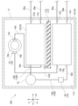
- FIG. 1 is a plan view of a vehicle refrigeration cycle unit according to a first embodiment
- FIG. It is a top view of the refrigerating-cycle unit for vehicles which concerns on 2nd embodiment.
- FIG. 7 is a plan view of a vehicle refrigeration cycle unit according to a third embodiment; It is a top view of the refrigerating-cycle unit for vehicles which concerns on 4th embodiment.
- 1 is a system diagram showing a configuration of a vehicle air conditioner (during cooling operation) according to an embodiment
- FIG. FIG. 5 is a plan view of a vehicle refrigeration cycle unit according to another embodiment;
- a vehicle air conditioner is a device mounted in an electric vehicle or the like, and conditions the air inside the vehicle. This vehicle air conditioner adjusts the temperature difference between the inside and outside of the vehicle body. In the present embodiment, a configuration in which the vehicle air conditioner performs heating operation will be described as an example.
- the vehicle air conditioner 1 includes a vehicle refrigeration cycle unit 100 , a vehicle interior heat medium circuit 20 , and a vehicle exterior heat medium circuit 30 .
- the lines in an open state through which the refrigerant can flow are indicated by solid lines.
- lines in a closed state in which the refrigerant cannot flow are indicated by dashed lines.
- black coating indicates a closed state
- white coating indicates an open state.
- the vehicle refrigerating cycle unit 100 is a device that circulates a primary refrigerant for exchanging heat with a secondary refrigerant used for air conditioning in the vehicle.
- a primary refrigerant in this embodiment for example, R290 refrigerant (propane), which is a highly flammable hydrocarbon, is adopted.
- the vehicle refrigeration cycle unit 100 includes a casing 11, a refrigeration cycle 10, various lines (a suction line 124, a discharge line 143, a pre-expansion line 136, and a post-expansion line 162), and a partition wall. 17 and.
- the casing 11 has a box-like shape and accommodates the refrigeration cycle 10 , the partition wall portion 17 , the suction line 124 , the discharge line 143 , the pre-expansion line 136 and the post-expansion line 162 inside.
- a refrigerating cycle 10 is composed of a plurality of devices that realize a thermodynamic cycle.
- the refrigerating cycle 10 repeatedly compresses, expands, evaporates, and condenses the primary refrigerant in order to exchange heat between the primary refrigerant as a heat medium and the secondary refrigerant, while sequentially circulating and circulating through a plurality of devices. circuit.
- the refrigeration cycle 10 has an evaporator 12 , a compressor 14 , a condenser 13 , a receiver 15 and an expansion valve 16 .
- the evaporator 12 is a plate-type evaporator that evaporates (vaporizes) the primary refrigerant by exchanging heat between the primary refrigerant that sequentially flows through the refrigeration cycle 10 and the secondary refrigerant that is introduced from the outside of the vehicle refrigeration cycle unit 100.
- a heat exchanger The primary refrigerant inside the evaporator 12 absorbs heat from the secondary refrigerant and cools the secondary refrigerant.
- the evaporator 12 is provided on the bottom surface 11 a of the casing 11 inside the casing 11 .
- the compressor 14 is a device that absorbs heat and compresses the vaporized primary refrigerant through the evaporator 12 .
- Compressor 14 and evaporator 12 are connected by suction line 124 . That is, one end of the suction line 124 is connected to the primary refrigerant outlet portion 12b of the evaporator 12, and the other end of the suction line 124 is connected to the suction port 14b of the compressor .
- the pressure of the primary refrigerant introduced into the compressor 14 is increased by compression of the compressor 14 to a predetermined pressure higher than before compression. This causes the temperature of the primary refrigerant to rise above that before compression.
- the compressor 14 has a compressor casing 14a, a suction port 14b, and a discharge port 14c.
- the compressor casing 14a has a cylindrical shape and is arranged to extend in the gravity direction G from the bottom surface 11a of the casing 11 inside the casing 11 .
- the compressor 14 in this embodiment is a so-called vertical compressor.
- a refrigerant compression mechanism is formed inside the compressor casing 14a.
- the suction port 14b is a refrigerant inlet for introducing refrigerant into the compressor casing 14a.
- the suction port 14b is provided at the end of the compressor casing 14a on the lower side in the direction of gravity G. As shown in FIG. The primary refrigerant is introduced into the compressor casing 14a through this suction port 14b.
- the discharge port 14c is a refrigerant outlet for discharging refrigerant from the compressor casing 14a.
- the discharge port 14c is provided at an upper end in the direction of gravity G in the compressor casing 14a.
- the primary refrigerant is discharged to the outside of the compressor casing 14a through this discharge port 14c.
- the discharge port 14c is the portion of the compressor 14 where the temperature is the highest.
- the condenser 13 exchanges heat between the primary refrigerant, which has a higher temperature and pressure than before being compressed by passing through the compressor 14, and the secondary refrigerant introduced from the outside of the vehicle refrigeration cycle unit 100.
- a plate heat exchanger that condenses (liquefies) the primary refrigerant.
- the condenser 13 is provided on the bottom surface 11 a of the casing 11 inside the casing 11 .
- the condenser 13 and the compressor 14 are connected by a discharge line 143. That is, one end of the discharge line 143 is connected to the discharge port 14 c of the compressor 14 , and the other end of the discharge line 143 is connected to the primary refrigerant inlet 13 a of the condenser 13 .
- the primary refrigerant inside the condenser 13 is cooled by the secondary refrigerant and at the same time increases the temperature of the secondary refrigerant.
- the gaseous primary refrigerant introduced into the condenser 13 is cooled by the secondary refrigerant and transitions to a liquid state after passing through a two-phase state of gas-liquid mixture. Therefore, the primary refrigerant that has passed through the condenser 13 becomes a liquid-mixed fluid.
- the condenser 13 is arranged inside the casing 11 so as to be adjacent to the compressor 14 .
- the direction in which the condenser 13 is adjacent to the compressor 14 (horizontal direction in FIG. 2) is referred to as the first adjacent direction H1
- the direction perpendicular to the first adjacent direction H1 (vertical direction in FIG. 2). direction) is referred to as a second adjacent direction H2.
- the first adjacent direction H1 and the second adjacent direction H2 are orthogonal to the direction of gravity G. As shown in FIG. Therefore, the horizontal direction is defined by the first adjacent direction H1 and the second adjacent direction H2.
- the evaporator 12 is adjacent to the condenser 13 from one side in the second adjacent direction H2. While the condenser 13 is adjacent to the compressor 14 in the first adjacent direction H1, the evaporator 12 is only horizontally spaced from the compressor 14 and is in the first adjacent direction H1 and the second It is not adjacent to the compressor 14 in either of the two adjacent directions H2. Therefore, the distance between compressor 14 and evaporator 12 is longer than the distance between compressor 14 and condenser 13 .
- the discharge port 14c of the compressor 14 in this embodiment faces the condenser 13 in the first adjacent direction H1. Therefore, the distance between the primary refrigerant discharge port 14 c and the evaporator 12 in the compressor 14 is longer than the distance between the discharge port 14 c and the condenser 13 . More specifically, the length of the pipe connecting the compressor 14 and the evaporator 12, namely the suction line 124, is longer than the length of the pipe connecting the compressor 14 and the condenser 13, namely the discharge line 143.
- adjacent in the first adjacent direction H1 means that, of two objects arranged side by side inside the casing 11, more than half the dimension of one in the second adjacent direction H2 is the same as that of the other. It means that the dimension in the second adjacent direction H2 overlaps with the dimension in the first adjacent direction H1.
- adjacent in the second adjacent direction H2 means that, of two objects arranged side by side inside the casing 11, more than half of the dimension of one in the first adjacent direction H1 is the same as the other. It means that the dimension in the first adjacent direction H1 overlaps with the dimension in the second adjacent direction H2.
- the receiver 15 receives the primary refrigerant that has become a gas-liquid mixed fluid by passing through the condenser 13, separates the primary refrigerant into a gas phase and a liquid phase, and temporarily holds them inside. It is a gas-liquid separator.
- the receiver 15 is provided on the bottom surface 11 a of the casing 11 inside the casing 11 .
- the receiver 15 and the condenser 13 are connected by the first line 135 of the pre-expansion line 136 . That is, one end of the first line 135 is connected to the primary refrigerant outlet portion 13 b of the condenser 13 , and the other end of the first line 135 is connected to the refrigerant inlet portion of the receiver 15 .
- the gas-liquid mixed primary refrigerant introduced into the receiver 15 flows into the liquid phase portion stored inside the receiver 15 .
- the liquid portion of the inflowing primary refrigerant is added to the liquid phase, and the remaining gas portion forms bubbles that move upward inside the receiver 15 and are added to the gas phase.
- the primary refrigerant stored as a liquid phase inside the receiver 15 is discharged outside the receiver 15 . As a result, the primary refrigerant in a liquid state is always provided from the receiver 15 .
- the expansion valve 16 is a device that receives the primary refrigerant in a liquid state through the receiver 15 and adiabatically expands the primary refrigerant.
- the expansion valve 16 is provided on the bottom surface 11 a of the casing 11 inside the casing 11 .
- the expansion valve 16 and the receiver 15 are connected by the second line 156 of the pre-expansion line 136 . That is, one end of the second line 156 is connected to the refrigerant outlet of the receiver 15 and the other end of the second line 156 is connected to the expansion valve 16 .
- the pressure of the primary refrigerant introduced into the expansion valve 16 is lowered to a predetermined pressure lower than before expansion due to the expansion action of the expansion valve 16 . This causes the temperature of the primary refrigerant to drop below that before expansion. Specifically, the primary refrigerant that has passed through the expansion valve 16 becomes a fluid in a liquid state, and is lowered to a temperature lower than the temperature of the secondary refrigerant that is a heat exchange destination.
- the expansion valve 16 and the evaporator 12 are connected by a post-expansion line 162 , and the primary refrigerant that has passed through the expansion valve 16 is introduced into the evaporator 12 through this post-expansion line 162 . That is, one end of the post-expansion line 162 is connected to the expansion valve 16 , and the other end of the post-expansion line 162 is connected to the primary refrigerant inlet portion 12 a of the evaporator 12 .
- the partition wall portion 17 is a heat insulating material provided between the evaporator 12 and the condenser 13 inside the casing 11 .
- the thermal conductivity of the partition 17 is lower than that of the casing 11 .
- the partition wall portion 17 in the present embodiment is a partition plate which is a plate member that stands up from the bottom surface 11a of the casing 11 inside the casing 11 toward the upper side in the direction of gravity G and separates the evaporator 12 and the condenser 13. 17a. That is, the longitudinal direction of the partition plate 17a coincides with the first adjacent direction H1. This suppresses heat transfer through the air between the evaporator 12 and the condenser 13 .
- the partition plate 17a provided on the bottom surface 11a between the evaporator 12 and the condenser 13
- heat conduction through the bottom portion of the casing 11 that constitutes the bottom surface 11a is achieved.
- Air convection and heat radiation from the condenser 13 to the evaporator 12 are suppressed.
- these heat conduction, convection, and heat radiation are collectively referred to as "heat transfer.”
- Rubber, resin, or the like, for example, is employed as a material for forming the partition plate 17a.
- the partition plate 17 may be made of the same material as the casing 11 .
- the vehicle-side heat medium circuit 20 is a refrigerant circuit for circulating the secondary refrigerant heat-exchanged with the primary refrigerant in the refrigerating cycle 10 and for conditioning the air inside the vehicle.
- Antifreeze liquid such as ethylene glycol is employed as a coolant liquid (cooling water), for example, as the secondary refrigerant in the present embodiment.
- the vehicle-inside heat medium circuit 20 includes a heater core 21 a (vehicle interior heat exchanger 21 ), a cooler core 21 b (vehicle interior heat exchanger 21 ), a first pump 22 , and a first valve 23 . , a second valve 24, and various lines (first heating medium line 20a to seventh heating medium line 20g).
- the heater core 21a and the cooler core 21b are heat exchangers for exchanging heat between the indoor air inside the vehicle body C, the outdoor air outside the vehicle body C, and the secondary refrigerant.
- Secondary refrigerant that has passed through the condenser 13 of the vehicle refrigeration cycle unit 100 is introduced into the heater core 21a.
- the secondary refrigerant passes through the first pump 22 and the first valve 23 during the process of introducing the secondary refrigerant from the condenser 13 to the heater core 21a.
- the first pump 22 is a pump that pumps the secondary refrigerant that has passed through the condenser 13 to the heater core 21a.
- a first heat medium line 20a as a flow path for sucking the secondary refrigerant into the first pump 22 connects the condenser 13 and the first pump 22 . That is, one end of the first heat medium line 20a is connected to the secondary refrigerant outlet 13d of the condenser 13, and the other end of the first heat medium line 20a is connected to the refrigerant suction port of the first pump 22. ing.
- a second heat medium line 20b as a flow path for discharging the secondary refrigerant from the first pump 22 toward the heater core 21a connects the first pump 22 and the first valve 23 . That is, one end of the second heat medium line 20b is connected to the refrigerant discharge port of the first pump 22, and the other end of the second heat medium line 20b is connected to the first valve .
- the first valve 23 is a three-way valve that can change the flow path (destination) of the secondary refrigerant.
- the first valve 23 and the heater core 21a are connected by a third heat medium line 20c. That is, one end of the third heat medium line 20c is connected to the first valve 23, and the other end of the third heat medium line 20c is connected to the heater core 21a.
- the secondary refrigerant introduced into the heater core 21a is cooled by exchanging heat with the indoor air and the outdoor air introduced into the vehicle body C, and at the same time, raises the temperature of the indoor air and the outdoor air.
- the air in the vehicle body C can be warmed by this.
- the outside air is, for example, the outside air outside the vehicle body C introduced by a blower (not shown) arranged upstream of the heater core 21a and the cooler core 21b.
- the secondary refrigerant cooled in the heater core 21a is returned to the condenser 13 via the second valve 24.
- the second valve 24 is a three-way valve that can change the flow path (destination) of the secondary refrigerant.
- the first valve 23 and the heater core 21a are connected by a fourth heating medium line 20d. That is, one end of the fourth heat medium line 20 d is connected to the refrigerant outlet of the heater core 21 a, and the other end of the fourth heat medium line 20 d is connected to the second valve 24 .
- the second valve 24 and the condenser 13 are connected by a fifth heat medium line 20e. That is, one end of the fifth heat medium line 20 e is connected to the second valve 24 and the other end of the fifth heat medium line 20 e is connected to the secondary refrigerant inlet 13 c of the condenser 13 .
- the secondary refrigerant sequentially flows through the condenser 13, the first pump 22, and the heater core 21a, and returns to the condenser 13. By repeating this circulation, the heating operation is realized, and the temperature rise in the vehicle can be maintained.
- the cooler core 21b is provided inside the vehicle body C independently of the heater core 21a.
- the secondary refrigerant that has passed through the evaporator 12 is introduced into the cooler core 21b during cooling operation, and heat is exchanged between the secondary refrigerant and the outside air. The flow of the secondary refrigerant during cooling operation will be described later.
- the vehicle-exterior heat medium circuit 30 is a refrigerant circuit for circulating the secondary refrigerant heat-exchanged with the primary refrigerant in the refrigerating cycle 10 and for cooling the battery for driving the vehicle body.
- the vehicle-exterior heat medium circuit 30 includes an exterior heat exchanger 31, a second pump 32, various valves (third valve 33 and fifth valve 35), a battery cooler 36, and various lines (eighth heat medium line 30a to twelfth heat medium line 30e, and first connection line 30f to fourth connection line 30i).
- the exterior heat exchanger 31 is a heat exchanger for exchanging heat between the outdoor air and the secondary refrigerant. Part of the secondary refrigerant that has passed through the evaporator 12 of the vehicle refrigeration cycle unit 100 is introduced into the exterior heat exchanger 31 via the third valve 33 . The remainder of the secondary refrigerant that has passed through the evaporator 12 is introduced into the battery cooler 36 via the fourth valve 34 .
- the evaporator 12, the third valve 33 and the fourth valve 34 are connected by an eighth heat medium line 30a.
- one end of the eighth heat medium line 30a is connected to the secondary refrigerant outlet 12d of the evaporator 12, and the other end of the eighth heat medium line 30a is connected to the middle of the eighth heat medium line 30a. It branches in two directions and is connected to the third valve 33 and the fourth valve 34, respectively.
- These third valve 33 and fourth valve 34 are three-way valves capable of changing the flow path (destination) of the secondary refrigerant.
- the third valve 33 and the exterior heat exchanger 31 are connected by a ninth heat medium line 30b. That is, one end of the ninth heat medium line 30 b is connected to the third valve 33 , and the other end of the ninth heat medium line 30 b is connected to the refrigerant inlet of the exterior heat exchanger 31 .
- the secondary refrigerant introduced into the exterior heat exchanger 31 through the eighth heat medium line 30a, the third valve 33, and the ninth heat medium line 30b absorbs heat by exchanging heat with the outside air.
- the temperature of the secondary refrigerant becomes higher than that of the primary refrigerant introduced into the evaporator 12 , and the temperature of the primary refrigerant flowing through the refrigeration cycle 10 within the evaporator 12 can be raised.
- Outside air to which heat is exchanged by the exterior heat exchanger 31 is supplied from the outside of the vehicle body C through the front grille F by the blower B provided on the front side inside the vehicle body C.
- the second pump 32 is a pump that pressure-feeds the secondary refrigerant whose temperature has been raised by the exterior heat exchanger 31 to the evaporator 12 .
- the secondary refrigerant that has passed through the exterior heat exchanger 31 passes through the fifth valve 35 while being sucked into the second pump 32 .
- the fifth valve 35 is a three-way valve capable of changing the flow path (destination) of the secondary refrigerant.
- the fifth valve 35 and the exterior heat exchanger 31 are connected by a tenth heat medium line 30c. That is, one end of the tenth heat medium line 30 c is connected to the exterior heat exchanger 31 , and the other end of the tenth heat medium line 30 c is connected to the fifth valve 35 .
- An eleventh heat medium line 30 d as a flow path for sucking the secondary refrigerant into the second pump 32 connects the fifth valve 35 and the second pump 32 . That is, one end of the eleventh heating medium line 30 d is connected to the fifth valve 35 and the other end of the eleventh heating medium line 30 d is connected to the second pump 32 .
- the second pump 32 and the evaporator 12 are connected by a twelfth heat medium line 30e. That is, one end of the twelfth heat medium line 30e is connected to the second pump 32, and the other end of the twelfth heat medium line 30e is connected to the secondary refrigerant inlet portion 12c of the evaporator 12. .
- the secondary refrigerant pressure-fed by the second pump is thereby introduced into the evaporator 12 .
- the secondary refrigerant sequentially flows through the evaporator 12 , the exterior heat exchanger 31 , and the second pump 32 and returns to the evaporator 12 .
- heat exchange in the evaporator 12 can maintain the temperature rise of the primary refrigerant circulating in the refrigeration cycle 10 .
- the vehicle refrigerating cycle unit 100 is interposed between the exterior heat exchanger 31 and the heater core 21a (the interior heat exchanger 21) to connect the exterior heat exchanger 31 and the interior heat exchanger 21. Heat is exchanged between the secondary refrigerants that flow respectively.
- the battery cooler 36 is a heat exchanger for cooling the battery.
- the battery cooler 36 is provided inside the vehicle body C. As shown in FIG. The remainder of the secondary refrigerant cooled by the evaporator 12 and flowing through the eighth heat medium line 30 a is introduced into the battery cooler 36 via the fourth valve 34 .
- the fourth valve 34 and the battery cooler 36 are connected by a first connection line 30f. That is, one end of the first connection line 30 f is connected to the fourth valve 34 , and the other end of the first connection line 30 f is connected to the coolant inlet of the battery cooler 36 .
- the secondary refrigerant warmed by heat exchange with the battery (not shown) in the battery cooler 36 is returned to the evaporator 12 .
- the battery cooler 36 and the eleventh heating medium line 30d are connected by a second connection line 30g.
- one end of the second connection line 30g is connected to the refrigerant outlet of the battery cooler 36, and the other end of the second connection line 30g is connected to the second pump 32 in the eleventh heat medium line 30d. is connected to a portion closer to the fifth valve 35 than the Therefore, the secondary refrigerant that has passed through the battery cooler 36 joins the eleventh heat medium line 30d via the second connection line 30g and is pressure-fed to the evaporator 12 again by the second pump 32 .
- the fourth valve 34 and the cooler core 21b are connected by a sixth heat medium line 20f. That is, one end of the sixth heat medium line 20f is connected to the fourth valve 34, and the other end of the sixth heat medium line 20f is connected to the refrigerant inlet of the heater core 21a.
- the cooler core 21b and the second connection line 30g are connected by a seventh heat medium line 20g. That is, one end of the seventh heat medium line 20g is connected to the cooler core 21b, and the other end of the seventh heat medium line 20g is connected to the second connection line 30g. Therefore, the secondary refrigerant that has passed through the evaporator 12 during cooling operation of the vehicle air conditioner 1 can flow into the cooler core 21 b via the fourth valve 34 .
- the fourth valve 34 allows the secondary refrigerant flowing from the eighth heat medium line 30a to flow only to the first connection line 30f without flowing to the sixth heat medium line 20f. That is, the fourth valve 34 supplies the secondary refrigerant only to the battery cooler 36 without supplying it to the cooler core 21b.
- first valve 23 and the fifth valve 35 are connected by a third connection line 30h. That is, one end of the third connection line 30 h is connected to the first valve 23 and the other end of the third connection line 30 h is connected to the fifth valve 35 .
- the first valve 23 allows the secondary refrigerant flowing from the second heat medium line 20b to flow only to the third heat medium line 20c without flowing to the third connection line 30h.
- the fifth valve 35 allows the secondary refrigerant flowing from the tenth heating medium line 30c to flow only to the eleventh heating medium line 30d without flowing to the third connection line 30h.
- the second valve 24 and the third valve 33 are connected by a fourth connection line 30i. That is, one end of the fourth connection line 30 i is connected to the second valve 24 and the other end of the fourth connection line 30 i is connected to the third valve 33 .
- the second valve 24 allows the secondary refrigerant flowing from the fourth heat medium line 20d to flow only to the fifth heat medium line 20e without flowing to the fourth connection line 30i.
- the third valve 33 allows the secondary refrigerant flowing from the eighth heat medium line 30a to flow only to the ninth heat medium line 30b without flowing to the fourth connection line 30i.
- the distance between the compressor 14 and the evaporator 12 that constitute the refrigeration cycle 10 is longer than the distance between the compressor 14 and the condenser 13 .
- the amount of heat such as radiant heat transmitted to the container 12 is less than the amount of heat transmitted to the condenser 13. - ⁇ Thereby, the temperature rise of the evaporator 12 caused by the compressor 14 can be suppressed more than the temperature rise of the condenser 13 caused by the compressor 14 . Therefore, a decrease in heat exchange efficiency between the primary refrigerant and the secondary refrigerant in the evaporator 12 can be suppressed.
- the distance between the primary refrigerant discharge port 14c and the evaporator 12 in the compressor 14 is longer than the distance between the discharge port 14c and the condenser 13.
- the amount of heat such as radiant heat transmitted to the evaporator 12 from the discharge port 14 c of 14 is smaller than the amount of radiant heat transmitted to the condenser 13 .
- the length of the pipe connecting the compressor 14 and the evaporator 12 is longer than the length of the pipe connecting the compressor 14 and the condenser 13. , heat is difficult to move from the compressor 14 to the evaporator 12 through these pipes. Thereby, there can exist an effect similar to the above.
- the vehicle refrigeration cycle unit 100 since the vehicle refrigeration cycle unit 100 according to the above-described embodiment includes the partition wall portion 17 between the condenser 13 and the evaporator 12 to separate the condenser 13 and the evaporator 12, the partition wall portion 17 Heat transfer from the condenser 13 to the evaporator 12 can be suppressed. Thereby, the temperature rise of the evaporator by the condenser can be suppressed.
- the partition wall portion 17 of the vehicle refrigeration cycle unit 100 is a plate member, it is possible to suppress heat transfer from the condenser 13 to the evaporator 12 with a simple structure of the plate member.
- a vehicle air conditioner 1 according to a second embodiment of the present disclosure will be described below.
- the vehicle refrigeration cycle unit 100 described in the second embodiment differs from the vehicle refrigeration cycle unit 100 of the first embodiment in the configuration of the partition wall portion 17 .
- Components similar to those in the first embodiment are denoted by the same reference numerals, and detailed description thereof is omitted.
- the partition wall 17 is a heat insulator provided between the evaporator 12 and the condenser 13 inside the casing 11 .
- the partition wall portion 17 in the present embodiment has a container 17 b that accommodates only the compressor 14 and the condenser 13 among the compressor 14 , the condenser 13 and the evaporator 12 that constitute the refrigeration cycle 10 . That is, the casing 11 and the container 17b are nested. The heat transfer between the evaporator 12 and the condenser 13 is suppressed by the partition wall of the container 17b. Rubber, resin, or the like, for example, is employed as the material forming the container 17b.
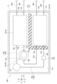
- the vehicle refrigeration cycle unit 100 described in the second embodiment has a positional relationship (arrangement) of the evaporator 12, the compressor 14, and the condenser 13 in the casing 11 with respect to the vehicle refrigeration cycle unit 100 of the first embodiment. ) are different. Components similar to those in the first embodiment are denoted by the same reference numerals, and detailed description thereof is omitted.
- the condenser 13 is arranged inside the casing 11 so as to be adjacent to the compressor 14 .
- the direction in which the condenser 13 is adjacent to the compressor 14 (vertical direction in FIG. 4) is referred to as the second adjacent direction H2, and the direction orthogonal to the second adjacent direction H2 (left and right in FIG. direction) is referred to as a first adjacent direction H1.
- the first adjacent direction H1 and the second adjacent direction H2 are orthogonal to the weight direction. That is, the horizontal direction is defined by the first adjacent direction H1 and the second adjacent direction H2.
- the evaporator 12 is adjacent to the condenser 13 from one side in the second adjacent direction H2, and the compressor 14 is adjacent to the condenser 13 from the other side in the second adjacent direction H2. That is, the condenser 13 is arranged between the compressor 14 and the evaporator 12 . Therefore, the distance between compressor 14 and evaporator 12 is longer than the distance between compressor 14 and condenser 13 .
- the discharge port 14c of the compressor 14 in this embodiment faces one side in the first adjacent direction H1, and the distance between the discharge port 14c and the evaporator 12 is greater than the distance between the discharge port 14c and the condenser 13. long. More specifically, the length of the piping or suction line 124 connecting the compressor 14 and the evaporator 12 is longer than the length of the piping or discharge line 143 connecting the compressor 14 and the condenser 13 .
- the condenser 13 is arranged between the compressor 14 and the evaporator 12, so the amount of heat such as radiant heat transmitted from the compressor 14 to the evaporator 12 is condensed. less than the amount of heat transmitted to the vessel 13. Therefore, it is possible to obtain the same effects as those of the first embodiment.
- a vehicle air conditioner 1 according to a fourth embodiment of the present disclosure will be described below.
- the vehicle refrigeration cycle unit 100 described in the fourth embodiment differs from the vehicle refrigeration cycle unit 100 of the third embodiment in the configuration of the partition wall portion 17 .
- Components similar to those of the third embodiment are denoted by the same reference numerals, and detailed description thereof is omitted.
- the partition 17 is a heat insulating material provided between the evaporator 12 and the condenser 13 inside the casing 11 .
- the partition wall portion 17 in the present embodiment has a container 17 b that accommodates only the compressor 14 and the condenser 13 among the compressor 14 , the condenser 13 and the evaporator 12 that constitute the refrigeration cycle 10 . That is, the casing 11 and the container 17b are nested.
- the partition wall of the container 17b suppresses direct heat transfer between the evaporator 12 and the condenser 13 via the air.
- the vehicle refrigeration cycle unit 100 described in the fifth embodiment differs from the vehicle refrigeration cycle unit 100 of the first embodiment in the arrangement of the compressor 14 .
- Components similar to those in the first embodiment are denoted by the same reference numerals, and detailed description thereof is omitted.
- the compressor 14 has a compressor casing 14a, a suction port 14b, and a discharge port 14c.
- the compressor casing 14a has a cylindrical shape and is arranged on the bottom surface 11a of the casing 11 inside the casing 11 so as to extend in the second adjacent direction H2.
- the compressor 14 in this embodiment is a so-called horizontal compressor.
- a refrigerant compression mechanism is formed inside the compressor casing 14a.
- the suction port 14b is a refrigerant inlet for introducing refrigerant into the compressor casing 14a.
- the suction port 14b is provided at one end of the compressor casing 14a in the second adjacent direction H2. That is, the suction port 14b is provided in the compressor casing 14a on the condenser 13 side of the evaporator 12 and the condenser 13 .
- the primary refrigerant is introduced into the compressor casing 14a through this suction port 14b.
- the suction port 14b is the portion of the compressor 14 where the temperature is the lowest.
- the discharge port 14c is a refrigerant outlet for discharging refrigerant from the compressor casing 14a.
- the discharge port 14c is provided at the end of the compressor casing 14a on the other side in the second adjacent direction H2. That is, the discharge port 14 c is provided in the compressor casing 14 a on the evaporator 12 side of the evaporator 12 and the condenser 13 .
- the primary refrigerant is discharged to the outside of the compressor casing 14a through this discharge port 14c.
- the discharge port 14c is the portion of the compressor 14 where the temperature is the highest. Therefore, the compressor casing 14a has a temperature distribution in which the temperature gradually rises from the suction port 14b side to the discharge port 14c side.
- the suction port 14b is provided in the compressor casing 14a on the condenser 13 side of the evaporator 12 and the condenser 13, and the discharge port 14c is provided on the evaporator 12 side.
- the amount of heat such as radiant heat transmitted from the compressor 14 to the evaporator 12 is smaller than the amount of heat transmitted to the condenser 13 . Therefore, it is possible to obtain the same effects as those of the first embodiment.
- the configuration in which the vehicle air conditioner 1 performs heating operation has been described as an example. A configuration similar to that can be adopted.
- configurations of the vehicle-interior heat medium circuit 20 and the vehicle-exterior heat medium circuit 30 during cooling operation will be described with reference to FIG.
- the first pump 22 pumps the secondary refrigerant condensed by the condenser 13 to the exterior heat exchanger 31 .
- a first heat medium line 20a as a flow path for sucking the secondary refrigerant into the first pump 22 connects the condenser 13 and the first pump 22 .
- a second heat transfer medium line 20 b as a flow path for discharging the secondary refrigerant from the first pump 22 toward the exterior heat exchanger 31 connects the first pump 22 and the first valve 23 .
- the first valve 23 allows the secondary refrigerant discharged from the first pump 22 to flow through the fourth connection line 30i without flowing through the third heat medium line 20c.
- the secondary refrigerant that has flowed into the fourth connection line 30 i flows into the third valve 33 .
- the third valve 33 allows the secondary refrigerant flowing from the fourth connection line 30i to flow to the tenth heat medium line 30c without flowing to the eleventh heat medium line 30d.
- the secondary refrigerant that has flowed into the tenth heat medium line 30 c flows into the exterior heat exchanger 31 .
- the secondary refrigerant that has passed through the exterior heat exchanger 31 flows into the fourth valve 34 via the ninth heat medium line 30b. Therefore, the flow direction of the secondary refrigerant flowing through the tenth heat medium line 30c, the exterior heat exchanger 31, and the ninth heat medium line 30b during refrigerant operation of the vehicle air conditioner 1 is the same as that of the secondary refrigerant during heating operation. opposite to the flow direction of
- the fourth valve 34 allows the secondary refrigerant flowing from the ninth heat medium line 30b to flow not to the eighth heat medium line 30a but to the third connection line 30h.
- the secondary refrigerant that has flowed into the third connection line 30 h flows into the second valve 24 .
- the second valve 24 allows the secondary refrigerant flowing from the third connection line 30h to flow through the fifth heat medium line 20e without flowing through the fourth heat medium line 20d.
- the secondary refrigerant that has flowed into the fifth heat medium line 20 e flows into the condenser 13 .
- the secondary refrigerant sequentially flows through the condenser 13, the first pump 22, and the exterior heat exchanger 31, and returns to the condenser 13.
- the primary refrigerant circulating in the refrigeration cycle 10 can be continuously cooled by heat exchange in the condenser 13 .
- the second pump 32 pumps the secondary refrigerant cooled by the evaporator 12 to the cooler core 21b.
- the secondary refrigerant that has passed through the evaporator 12 due to the suction force of the pump flows into the eighth heat medium line 30 a and into the fifth valve 35 .
- the fifth valve 35 allows the secondary refrigerant flowing from the eighth heat medium line 30a to flow through both the sixth heat medium line 20f and the first connection line 30f.
- the secondary refrigerant that has flowed into the sixth heat medium line 20f flows into the cooler core 21b.
- the secondary refrigerant that has finished heat exchange in the cooler core 21b flows into the seventh heat medium line 20g and then into the second connection line 30g.
- the secondary refrigerant that has flowed into the second connection line 30g flows into the eleventh heat medium line 30d and returns to the evaporator 12 via the second pump 32 and the twelfth heat medium line 30e.
- the secondary refrigerant that has flowed into the first connection line 30 f flows into the battery cooler 36 . Therefore, the battery cooler 36 exchanges heat (is cooled) with the secondary refrigerant both during the heating operation and the cooling operation of the vehicle air conditioner 1 .
- the secondary refrigerant that has finished heat exchange in the battery cooler 36 flows into the second connection line 30g.
- the secondary refrigerant that has flowed into the second connection line 30g flows into the eleventh heat medium line 30d and returns to the evaporator 12 via the second pump 32 and the twelfth heat medium line 30e.
- the secondary refrigerant sequentially flows through the evaporator 12, the cooler core 21b, and the second pump 32, and returns to the evaporator 12.
- cooling operation is realized, and the interior of the vehicle can be kept cool.
- the partition plate 17a included in the partition wall portion 17 in the above embodiment is not limited to the configurations of the first embodiment and the third embodiment.
- the partition plate 17 a may be arranged to separate the condenser 13 and the evaporator 12 and to separate the expansion valve 16 and the evaporator 12 inside the casing 11 . Thereby, heat transfer to the evaporator 12 can be further suppressed.
- R290 refrigerant was exemplified as the primary refrigerant and ethylene glycol was exemplified as the secondary refrigerant in the above embodiment, other refrigerants may be used as the primary refrigerant and the secondary refrigerant.
- the vehicle-exterior heat medium circuit 30 in the above-described embodiment includes a running motor cooler (not shown) that is a heat exchanger for cooling a running motor, and a heat exchanger that cools an inverter (power conversion device). You may further have an inverter cooler (not shown) as.
- the secondary refrigerant that has passed through the exterior heat exchanger 31 passes through piping (not shown) that connects the exterior heat exchanger 31 and the travel motor cooler and inverter cooler to the travel motor and inverter. Cooling water is introduced into each of the traveling motor cooler and the inverter cooler.
- the secondary refrigerant warmed by heat exchange in the running motor cooler and the inverter cooler flows from the battery cooler 36 toward the eleventh heat medium line 30d through the second connection line 30g. Like the refrigerant, it may flow into the eleventh heating medium line 30d through the piping.
- the vehicle refrigeration cycle unit 100 in the above embodiment has an upper surface facing upward in the direction of gravity G, and the evaporator 12 and the compressor 14 are interposed between the refrigeration cycle 10 and the bottom surface 11 a of the casing 11 . , and a bracket that secures the condenser 13 to this top surface.
- the bracket fixes the refrigerating cycle 10 to the upper surface while being fixed to the inner wall surface of, for example, the front compartment outside the passenger compartment. Therefore, the refrigerating cycle 10 may be configured to be provided on the bottom surface 11a of the casing 11 via a bracket. In this case, the thermal conductivity of the partition wall portion 17 is lower than that of the bracket.
- the vehicle refrigeration cycle unit 100 is interposed between the exterior heat exchanger 31 and the interior heat exchanger 21, and A refrigerating cycle unit 100 for a vehicle that exchanges heat between secondary refrigerants respectively circulating through 21, and has a compressor 14, a condenser 13, an expansion valve 16, and an evaporator 12 through which primary refrigerants sequentially flow.
- a cycle (10) is provided, wherein the distance between the compressor (14) and the evaporator (12) is greater than the distance between the compressor (14) and the condenser (13).
- the amount of heat such as radiation heat transmitted from the compressor 14 to the evaporator 12 is less than the amount of heat transmitted to the condenser 13.
- the vehicle refrigeration cycle unit 100 is interposed between the exterior heat exchanger 31 and the interior heat exchanger 21, and A refrigerating cycle unit 100 for a vehicle that exchanges heat between secondary refrigerants respectively circulating through a refrigerating cycle unit 100 having a compressor 14, a condenser 13, an expansion valve 16, and an evaporator 12 through which the primary refrigerants sequentially circulate. 10 , the distance between the outlet 14 c of the primary refrigerant in the compressor 14 and the evaporator 12 is longer than the distance between the outlet 14 c and the condenser 13 .
- the amount of heat such as radiant heat transmitted from the discharge port 14 c of the compressor 14 to the evaporator 12 is less than the amount of radiation heat transmitted to the condenser 13 .
- the vehicle refrigeration cycle unit 100 is interposed between the exterior heat exchanger 31 and the interior heat exchanger 21, and A refrigerating cycle unit 100 for a vehicle that exchanges heat between secondary refrigerants respectively circulating through a refrigerating cycle unit 100 having a compressor 14, a condenser 13, an expansion valve 16, and an evaporator 12 through which the primary refrigerants sequentially circulate.
- the length of the pipe connecting the compressor 14 and the evaporator 12 is longer than the length of the pipe connecting the compressor 14 and the condenser 13 .
- a vehicular refrigeration cycle unit 100 according to a fourth aspect is the vehicular refrigeration cycle unit 100 according to any one of (1) to (3), in which between the compressor 14 and the evaporator 12 The condenser 13 may be arranged in the .
- the amount of heat such as radiation heat transmitted from the compressor 14 to the evaporator 12 is less than the amount of heat transmitted to the condenser 13.
- a vehicle refrigeration cycle unit 100 according to a fifth aspect is the vehicle refrigeration cycle unit 100 according to any one of (1) to (3), in which the condenser 13 and the evaporator 12 are provided with a Furthermore, a partition wall portion 17 separating the condenser 13 and the evaporator 12 may be further provided.
- a vehicle refrigeration cycle unit 100 according to a sixth aspect is the vehicle refrigeration cycle unit 100 of (5), wherein the partition wall portion 17 may have a partition plate 17a that is a plate member. .
- a vehicle refrigeration cycle unit 100 according to a seventh aspect is the vehicle refrigeration cycle unit 100 of (5), wherein the partition wall portion 17 includes the compressor 14, the condenser 13 and the evaporator. 12, a housing body 17b for housing only the compressor 14 and the condenser 13 may be provided.
- a vehicle air conditioner 1 includes the vehicle refrigeration cycle unit 100 according to any one of (1) to (7), the vehicle exterior heat exchanger 31, and the vehicle interior heat exchanger 21. And prepare.
Abstract
L'invention concerne une unité de cycle de réfrigération pour véhicule qui est interposée entre un échangeur de chaleur extérieur de véhicule et un échangeur de chaleur intérieur de véhicule et réalise un échange de chaleur entre des fluides frigorigènes secondaires s'écoulant à travers l'échangeur de chaleur intérieur de véhicule et l'échangeur de chaleur extérieur de véhicule, respectivement, l'unité de cycle de réfrigération pour véhicule étant pourvue d'un cycle de réfrigération comprenant un compresseur, un condenseur, une soupape de détente et un évaporateur à travers lequel un fluide frigorigène primaire s'écoule de manière séquentielle, et la distance entre le compresseur et l'évaporateur est supérieure à la distance entre le compresseur et le condenseur.
Priority Applications (1)
| Application Number | Priority Date | Filing Date | Title |
|---|---|---|---|
| PCT/JP2021/040610 WO2023079637A1 (fr) | 2021-11-04 | 2021-11-04 | Unité de cycle de réfrigération pour véhicule et climatiseur pour véhicule |
Applications Claiming Priority (1)
| Application Number | Priority Date | Filing Date | Title |
|---|---|---|---|
| PCT/JP2021/040610 WO2023079637A1 (fr) | 2021-11-04 | 2021-11-04 | Unité de cycle de réfrigération pour véhicule et climatiseur pour véhicule |
Publications (1)
| Publication Number | Publication Date |
|---|---|
| WO2023079637A1 true WO2023079637A1 (fr) | 2023-05-11 |
Family
ID=86240808
Family Applications (1)
| Application Number | Title | Priority Date | Filing Date |
|---|---|---|---|
| PCT/JP2021/040610 WO2023079637A1 (fr) | 2021-11-04 | 2021-11-04 | Unité de cycle de réfrigération pour véhicule et climatiseur pour véhicule |
Country Status (1)
| Country | Link |
|---|---|
| WO (1) | WO2023079637A1 (fr) |
Citations (4)
| Publication number | Priority date | Publication date | Assignee | Title |
|---|---|---|---|---|
| JP2019086165A (ja) * | 2017-11-01 | 2019-06-06 | 三星電子株式会社Samsung Electronics Co.,Ltd. | 冷蔵庫 |
| JP2019182036A (ja) * | 2018-04-03 | 2019-10-24 | 株式会社デンソー | 空調装置 |
| JP2021008981A (ja) * | 2019-07-01 | 2021-01-28 | 三菱重工サーマルシステムズ株式会社 | 空気調和ユニット、熱交換器、および空気調和機 |
| JP2021123131A (ja) * | 2020-01-31 | 2021-08-30 | 三菱重工サーマルシステムズ株式会社 | 車両用空調装置 |
-
2021
- 2021-11-04 WO PCT/JP2021/040610 patent/WO2023079637A1/fr unknown
Patent Citations (4)
| Publication number | Priority date | Publication date | Assignee | Title |
|---|---|---|---|---|
| JP2019086165A (ja) * | 2017-11-01 | 2019-06-06 | 三星電子株式会社Samsung Electronics Co.,Ltd. | 冷蔵庫 |
| JP2019182036A (ja) * | 2018-04-03 | 2019-10-24 | 株式会社デンソー | 空調装置 |
| JP2021008981A (ja) * | 2019-07-01 | 2021-01-28 | 三菱重工サーマルシステムズ株式会社 | 空気調和ユニット、熱交換器、および空気調和機 |
| JP2021123131A (ja) * | 2020-01-31 | 2021-08-30 | 三菱重工サーマルシステムズ株式会社 | 車両用空調装置 |
Similar Documents
| Publication | Publication Date | Title |
|---|---|---|
| JP5626194B2 (ja) | 熱交換システム | |
| JP5659925B2 (ja) | 車両用空調装置 | |
| JP6610800B2 (ja) | 機器温調装置 | |
| JP6575690B2 (ja) | 機器温調装置 | |
| WO2018047533A1 (fr) | Appareil de réglage de température de dispositif | |
| CN109203908A (zh) | 用于车辆的集中能量模块 | |
| WO2018047540A1 (fr) | Appareil de réglage de température de dispositif | |
| US10919361B2 (en) | Cooling module for vehicle | |
| JP2014218211A (ja) | 車両用熱管理システム | |
| JP2013119373A (ja) | 車両用コンデンサ | |
| WO2014002369A1 (fr) | Cycle de pompe à chaleur | |
| WO2020179651A1 (fr) | Module de refroidissement destiné à refroidir une batterie de véhicule | |
| WO2018047538A1 (fr) | Système de régulation de température de dispositif | |
| JP5264442B2 (ja) | 車両用空調装置 | |
| KR20160129165A (ko) | 차량용 히트 펌프 시스템 | |
| WO2023079637A1 (fr) | Unité de cycle de réfrigération pour véhicule et climatiseur pour véhicule | |
| CN113474188A (zh) | 换热器及车辆空调系统 | |
| WO2020246337A1 (fr) | Échangeur de chaleur et dispositif à cycle frigorifique | |
| JP2014118140A (ja) | 車両用クーリングモジュール | |
| WO2023079630A1 (fr) | Unité à cycle de réfrigération pour véhicule | |
| KR102609386B1 (ko) | 열교환기 및 이를 포함하는 차량용 공조장치 | |
| US9834061B2 (en) | Assembly including a heat exchanger and a mounting on which said exchanger is mounted | |
| JPH1047811A (ja) | コンデンサ | |
| JP2017040421A (ja) | 熱交換器及びヒートポンプシステム | |
| WO2018070182A1 (fr) | Appareil de régulation de température d'appareil ménager |
Legal Events
| Date | Code | Title | Description |
|---|---|---|---|
| 121 | Ep: the epo has been informed by wipo that ep was designated in this application |
Ref document number: 21963234 Country of ref document: EP Kind code of ref document: A1 |