WO2023074868A1 - 摺動部材 - Google Patents
摺動部材 Download PDFInfo
- Publication number
- WO2023074868A1 WO2023074868A1 PCT/JP2022/040472 JP2022040472W WO2023074868A1 WO 2023074868 A1 WO2023074868 A1 WO 2023074868A1 JP 2022040472 W JP2022040472 W JP 2022040472W WO 2023074868 A1 WO2023074868 A1 WO 2023074868A1
- Authority
- WO
- WIPO (PCT)
- Prior art keywords
- sliding
- copper
- phosphate coating
- manganese
- manganese phosphate
- Prior art date
- Legal status (The legal status is an assumption and is not a legal conclusion. Google has not performed a legal analysis and makes no representation as to the accuracy of the status listed.)
- Ceased
Links
Images

Classifications
-
- F—MECHANICAL ENGINEERING; LIGHTING; HEATING; WEAPONS; BLASTING
- F16—ENGINEERING ELEMENTS AND UNITS; GENERAL MEASURES FOR PRODUCING AND MAINTAINING EFFECTIVE FUNCTIONING OF MACHINES OR INSTALLATIONS; THERMAL INSULATION IN GENERAL
- F16C—SHAFTS; FLEXIBLE SHAFTS; ELEMENTS OR CRANKSHAFT MECHANISMS; ROTARY BODIES OTHER THAN GEARING ELEMENTS; BEARINGS
- F16C33/00—Parts of bearings; Special methods for making bearings or parts thereof
- F16C33/02—Parts of sliding-contact bearings
-
- F—MECHANICAL ENGINEERING; LIGHTING; HEATING; WEAPONS; BLASTING
- F16—ENGINEERING ELEMENTS AND UNITS; GENERAL MEASURES FOR PRODUCING AND MAINTAINING EFFECTIVE FUNCTIONING OF MACHINES OR INSTALLATIONS; THERMAL INSULATION IN GENERAL
- F16C—SHAFTS; FLEXIBLE SHAFTS; ELEMENTS OR CRANKSHAFT MECHANISMS; ROTARY BODIES OTHER THAN GEARING ELEMENTS; BEARINGS
- F16C33/00—Parts of bearings; Special methods for making bearings or parts thereof
- F16C33/30—Parts of ball or roller bearings
Definitions
- the present invention relates to a sliding member, and more particularly to a combination sliding member including a plurality of sliding members that slide against each other.
- Combination sliding members include, for example, rolling bearings and housings.
- a combination sliding member including members formed of materials with different hardness, such as a valve and a valve body, has been used.
- a combined sliding member for example, a first sliding component made of an aluminum alloy having an alumite layer formed on the sliding surface, and a sliding surface of the first sliding component that slides on the sliding surface to provide a predetermined
- Patent Document 1 includes a second sliding component made of polymer resin, reinforcing fibers, and solid lubricant.
- a sintering step is required to form a layer of polymeric resin containing a solid lubricant or the like. Therefore, from the viewpoint of global warming, for which countermeasures are required these days, there is a problem of reducing the amount of greenhouse gases generated in the life cycle assessment.
- a polymer resin layer containing a solid lubricant or the like is formed on the sliding surface in contact with the housing. A firing process is required, which complicates the manufacturing process of the bearing and produces greenhouse gases.
- a relatively complicated process such as an anodizing treatment using an acidic treatment liquid is required, and power consumption increases. do.
- the present invention has been made in view of these points, and according to the present invention, a combined sliding surface that has low environmental load, can be manufactured by a simple method, and is excellent in wear resistance, durability, etc. It is possible to provide a member, for example, a combined sliding member capable of suppressing housing wear due to rolling bearing creep.
- the above problems have been solved by the present invention.
- the present invention includes the following. [1] A combined sliding member comprising a first sliding component made of aluminum or an aluminum alloy and a second sliding component made of steel, A surface of the second sliding part that slides against the first sliding part has a copper-containing manganese phosphate coating, and the manganese phosphate coating contains 1.5 g/m 2 of manganese. above, the copper/manganese content ratio is 0.02 to 2.56, A combination sliding member, wherein a surface roughness Ra of a surface of the first sliding part that slides on the second sliding part is 2.9 ⁇ m or less.
- the rolling bearing as the second sliding component is An outer ring, an inner ring, and a plurality of rolling elements arranged to be rollable between the outer ring and the inner ring,
- sliding member. [5] A combined sliding member comprising a first sliding component made of aluminum or an aluminum alloy and a second sliding component made of steel, A surface of the second sliding part that slides on the first sliding part has a copper-containing manganese phosphate coating, and the manganese phosphate coating has a manganese content of 2.1 g/m 2 .
- the copper/manganese content ratio is 0.04 to 0.62
- a combination sliding member wherein a surface roughness Ra of a surface of the first sliding part that slides on the second sliding part is 2.9 ⁇ m or less.
- the second sliding component is an SUJ material defined in JIS G4805:2008.
- the manganese phosphate coating has a thickness of 1 to 25 ⁇ m.
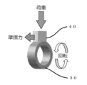
- FIG. 10 is a diagram showing an example of an SEM enlarged observation image of a copper-containing manganese phosphate coating in Example 2; It is a figure which shows roughly about the method of a sliding performance test (abrasion resistance test).
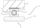
- FIG. 4 is a partial cross-sectional view showing an example of a combined sliding member of a rolling bearing and a housing;
- the combined sliding member of the present invention includes at least a first sliding component and a second sliding component, wherein the sliding surfaces of the first sliding component and the second sliding component are in contact with each other and slide. is configured as Each member will be described below.
- the first sliding part is made of aluminum or an aluminum alloy.
- Specific examples of aluminum and aluminum alloys contained in the first sliding component include the following alloy symbols defined in JIS H4000:2017. In other words, 1085, 1080, 1060, 1060 ,1050 ,1200, 1N00, 1N00, 1N30, 1230, 2017, 2017, 2219, 2219, 2219, 2219, 3103, 3203, 3204, 3104, 3105, 3003, 3003, 3003, 3003, 3003, 3003, 3003, 3003, 3003, 3003, 3003, 3003, 3003, 3003, 3003, 3003.
- the first sliding component may contain only one of the aluminum and aluminum alloys described above, or may contain more than one.
- the first sliding component has a sliding surface (first sliding surface) in contact with the second sliding component.
- the surface roughness is adjusted on the first sliding surface. That is, the value of the arithmetic mean roughness Ra conforming to JIS B 0601-2001 on the first sliding surface is 2.9 ⁇ m or less.
- the Ra value of the first sliding surface is preferably 2.5 ⁇ m or less, more preferably 2.2 ⁇ m or less, still more preferably 2.0 ⁇ m or less, and particularly preferably 1.8 ⁇ m or less. , 1.5 ⁇ m or less, 1.2 ⁇ m or less, 1.0 ⁇ m or less, or 0.8 ⁇ m or less.
- the lower limit of the Ra value is not particularly important. It is 2 ⁇ m or more, 0.3 ⁇ m or more, or 0.4 ⁇ m or more. A method for measuring the value of the arithmetic mean roughness Ra will be described later.
- the second sliding part contains at least steel.
- steel base material symbols SUJ1, SUJ2, SUJ3, SUJ4, SUJ5 (SUJ material: high carbon chromium bearing steel material), SCr415, SCr420, SCr435 (SCr material: chrome steel material), SCM415, SCM418, SCM420, SCM421, SCM425, SCM430, SCM432, SCM435, SCM440, SCM445, SCM822 (SCM material: chromium molybdenum steel material), SNCM220 , SNCM420, SNCM815 (SNCM material: nickel-chromium-molybdenum steel), SUS440, SUS403, SUS410, SUS410J1, SUS410F2, SUS416, SUS420J1, SUS420J2, SUS420F, SUS420F2, SUS431, SUS440A
- the steel material described above can be used regardless of the type of the second sliding component, and is preferably used in bearings such as rolling bearings, for example.
- Further specific examples of the steel material contained in the second sliding part include carbon steel, cold-rolled steel plate (SPCC), carbon steel pipe for machine structural use (STKM material), carbon tool steel (SK material), alloy tool steel (SKS materials), sintered materials for machine structural parts, and other structural special steels. These steel materials can also be employed regardless of the type of the second sliding component, and are preferably used for components other than bearings, for example.
- the steel material of the second sliding part may be subjected to a predetermined heat treatment such as quenching and tempering, carburizing or carbonitriding, quenching and tempering.
- the second sliding component may contain only one of the steel materials described above, or may contain more than one.
- Copper-containing manganese phosphate coating (phosphate coating) A copper-containing manganese phosphate coating is formed on the sliding surface (second sliding surface) of the second sliding component that is in contact with the first sliding component. The manganese phosphate coating is arranged on the surface of the second sliding surface so as to be in contact with the first sliding surface.
- Manganese phosphate coatings contain copper and manganese.
- a manganese phosphate coating containing copper specifically, there is a form in which the copper compound added during the formation of the manganese phosphate coating co-deposits in the manganese phosphate coating as shown in FIG.
- the manganese content (content based on the unit area of the coating) is 1.5 g/m 2 or more, preferably 1.7 g/m 2 or more, more preferably , 2.0 g/m 2 or more, or 2.1 g/m 2 or more.
- the manganese content in the manganese phosphate coating is more preferably 2.3 g/m 2 or more, more preferably 2.5 g/m 2 or more, and more preferably 3.0 g/m 2 or more. Especially preferred. Regarding the content of manganese in the manganese phosphate coating, the lower limit is important, and the upper limit is not particularly limited. It may be 8.0 g/m 2 or less. In the manganese phosphate coating, the value of the content ratio (weight ratio) of copper/manganese, that is, the ratio of the content of copper and manganese per unit area contained in the manganese phosphate coating is from 0.02 to 0.02.
- the content ratio (weight ratio) of copper/manganese is 0.02 or more, preferably 0.05 or more, 0.10 or more, or 0.15 or more, more preferably 0.20 or more, or 0.22 or more. , or greater than or equal to 0.25.
- the value of the content ratio of copper/manganese is 2.56 or less, preferably 2.20 or less, 2.00 or less, or 1.80 or less, more preferably 1.60 or less, 1.40 less than or equal to 1.30.
- the content ratio (weight ratio) of copper/manganese in the manganese phosphate coating is preferably in the range of 0.04 to 0.62.
- the content ratio value is preferably in the range of 0.06 to 0.50, more preferably in the range of 0.08 to 0.40, and in the range of 0.10 to 0.30 more preferably within.
- Phosphate coatings other than manganese phosphate coatings may be used, and specific examples thereof include zinc phosphate coatings, zinc calcium phosphate coatings, manganese phosphate coatings as well as manganese-containing phosphate coatings. zinc-manganese coating;
- the phosphate coating containing a metal other than manganese phosphate and copper co-deposit as in the manganese phosphate coating.
- the content of the phosphate-derived metal in the phosphate coating and the range of the weight ratio of the phosphate-derived metal to copper are the same as in the manganese phosphate coating described above. That is, in the phosphate coating containing metals other than manganese, the total content of phosphate-derived metals is preferably 2.1 g/m 2 or more, and preferably 2.3 g/m 2 or more. is more preferably 2.5 g/m 2 or more, and particularly preferably 3.0 g/m 2 or more.
- the lower limit is important, and the upper limit is not particularly limited, but for example, 15 g/ m2 or less. , 12 g/m 2 or less, 10 g/m 2 or less, or 8.0 g/m 2 or less.
- the content ratio (weight ratio) of the total amount of copper/phosphate-derived metal is, for example, 0.02 to 2.56, preferably 0.05 to 2.20, 0.10 to 2.00 or 0.15 to 1.80, more preferably 0.20 to 1.60, 0.22 to 1.40 or 0.25 to 1 .30.
- the value of the content ratio (weight ratio) of the total amount of copper/phosphate-derived metals is, for example, 0.02 or more, preferably 0.05 or more, 0.10 or more, or 0.15 or more, more preferably is greater than or equal to 0.20, greater than or equal to 0.22, or greater than or equal to 0.25.
- the value of the content ratio (weight ratio) of the total amount of copper/phosphate-derived metals is, for example, 2.56 or less, preferably 2.20 or less, 2.00 or less, or 1.80 or less. and more preferably 1.60 or less, 1.40 or less, or 1.30 or less.
- the value of the content ratio (weight ratio) of the total amount of copper/phosphate-derived metals in the phosphate coating is preferably in the range of 0.04 to 0.62.
- the weight ratio range is preferably in the range of 0.06 to 0.50, more preferably in the range of 0.08 to 0.40, and in the range of 0.10 to 0.30. It is even more preferable to have
- the manganese phosphate coating contains copper co-deposited with the formation of the manganese phosphate coating, and various phosphates are included as other components. It may be
- the phosphate coating is preferably a manganese phosphate coating, but may be a zinc phosphate coating or a zinc calcium phosphate coating. However, from the viewpoint of improving the adhesion and slidability of the phosphate coating, it is preferable to use a manganese phosphate coating or a zinc manganese phosphate coating.
- a copper-containing phosphate coating is formed with various phosphate solutions.
- manganese phosphate-based treatment agents, zinc phosphate-based treatment agents, zinc calcium phosphate-based treatment agents, and zinc manganese phosphate-based treatment agents are preferably used (for example, phosphorus
- a copper-containing phosphate film is formed by a mixed treatment solution in which a compound containing copper ions is added to a treatment solution that has been appropriately adjusted using manganese acid treatment agents such as PF-M1A and PF-M5). is formed.
- the phosphate solution preferably contains the following compound as a copper ion supply source for codepositing copper together with the phosphate. That is, examples of the copper ion supply source include copper (II) nitrate, aqueous solutions of copper (I) chloride, copper (II) chloride, copper (II) sulfate, metallic copper, and the like.
- a copper-containing phosphate coating may be formed by adding to the phosphating solution described above and using the added treating solution. The copper-containing phosphate coating is formed by, for example, immersing the second sliding component, which has been subjected to pretreatments such as cleaning and degreasing, in the mixed treatment liquid described above by a general method.
- the value of the copper/manganese weight ratio is 0.02 to 2.56, preferably 0.04 to 0.62.
- the value of the weight ratio of the total amount of metals is also preferably adjusted within the range of 0.02 to 2.56, preferably 0.04 to 0.62. Therefore, the content of the copper ion source contained in the phosphate solution is appropriately adjusted so that the weight ratio range can be achieved.
- Additives such as sources of metals nobler than iron, such as tin, lead, silver, and gold, are added to the phosphate solution in conjunction with or in place of the copper ion sources described above. good too.
- a resin-based additive may be used together with the metal (metal ion) supply source such as copper, or instead of the metal (metal ion) supply source. That is, fluorine-based resins (such as polytetrafluoroethylene) and polyolefin-based resins (such as polyethylene) that can be dispersed in a solution that is mainly an aqueous solution can also be used.
- the weight ratio of the total of the additive-derived components derived from the above-described copper ion source and the like used as an additive to the phosphate-derived metal such as manganese is also preferably 0. It is preferably adjusted within the range of 0.02 to 2.56, more preferably 0.04 to 0.62. Therefore, the total content of the additives contained in the phosphate solution is also appropriately adjusted so that the range of the weight ratio in the phosphate coating can be achieved.
- the thickness of the phosphate coating such as the manganese phosphate coating is appropriately adjusted depending on the use of the sliding member, and is, for example, 1 ⁇ m to 25 ⁇ m. Below is.
- the thickness of the phosphate coating is preferably 2 ⁇ m or more and 20 ⁇ m or less, more preferably 3 ⁇ m or more and 15 ⁇ m or less, and particularly preferably 4 ⁇ m or more and 10 ⁇ m or less.
- the wear depth is preferably 50 ⁇ m or less, preferably 40 ⁇ m or less, and 30 ⁇ m or less in a sliding performance test described later in detail. is more preferable, and 25 ⁇ m or less is particularly preferable.
- a baked coating containing a solid lubricant may be formed on the phosphate coating such as the manganese phosphate coating.
- the phosphate coating such as the manganese phosphate coating.
- it is a fired film containing an organic binder, a curing agent, a solid lubricant, and the like.
- a sintering process is required to heat the material such as the sintered film, and depending on the sintering process, carbon dioxide, which is a greenhouse gas, is also emitted. . Therefore, if only a phosphate film containing a predetermined component such as copper is provided by a simple method as described above, it is possible to improve the efficiency of the manufacturing process and reduce the generation of greenhouse gases.
- Both the first and second sliding parts can be manufactured based on known techniques.
- the value of the surface roughness Ra of the first sliding surface is measured by a method described in detail below in order to confirm whether the surface roughness Ra of the first sliding surface is adjusted within a predetermined range. is preferred. Then, when the value of the surface roughness Ra is out of the predetermined range, the surface roughness is adjusted by a known method such as lathe turning.
- a phosphate coating is formed, for example, by the method described above.
- the combined sliding member described above is used in various applications, and can be widely used particularly in members made of a combination of aluminum and steel materials.
- the parts in which the first sliding part containing aluminum or aluminum alloy/second sliding part containing steel material can be used include valves/valve bodies, rocker arms/rocker shafts, pistons/piston rings, pistons/pistons, Pins, pistons/cylinders, housings/bearings (eg, rolling bearings, slide bearings, etc.), electric steering columns (case housings (aluminum)/pipes (eg, steel tubes for mechanical structures (STKM), etc.)).
- a preferred combination of the above-described first sliding component/second sliding component that is, a preferred form of the combined sliding member includes a housing and a bearing, such as a housing and a rolling bearing.
- An example of a combined housing and bearing sliding member is shown schematically in the partial cross-sectional view of FIG. In FIG. 3 the combined sliding member comprising the rolling bearing 1 and the housing 5 is installed in a rotating device with a rotating member 7 .
- the rolling bearing 1 is preferably made of a steel material such as SUJ material such as SUJ2, SCr material, SCM material, or SNCM material, and the housing 5 is preferably made of an aluminum alloy.
- a rolling bearing 1 includes an outer ring 2 , an inner ring 3 , and a plurality of rolling elements (balls) 4 interposed between the outer ring 2 and the inner ring 3 .
- the rolling bearing 1 holds a rotating shaft member 7 that rotates around a rotating shaft 7a.
- one of the outer ring 2 and the inner ring 3 is a rotating ring, and the other is a stationary ring.
- a manganese phosphate coating 2a containing copper is formed on the surface of the fixed ring, for example, the outer ring 2, which contacts the housing 5.
- the coating may be provided only on the top surface of the outer diameter surface, which is the surface of the outer ring 2, which is the fixed ring, and which is the surface on the housing side.
- the side surface in contact with the housing 5 in FIG. 3, the surface on the lower left of the top surface where the coating 2a is provided
- the coating may be provided, and preferably, the coating is provided on the entire region of the sliding surface of the outer diameter surface of the outer ring 2 that slides against the housing 5 .
- the outer ring rotating type bearing may be provided with a copper-containing manganese phosphate coating.
- a copper-containing manganese phosphate coating is formed on at least a portion of the inner diameter surface of the inner ring.
- the manganese phosphate coating may be provided only on a partial region of the sliding surface of the inner diameter surface of the inner ring that slides against the housing. It is preferable that the coating is provided over the entire area of the surface.
- the surface roughness Ra is adjusted to 2.9 ⁇ m or less in the region in contact with the fixed ring such as the outer ring 2 .
- the combination sliding member on which the manganese phosphate coating is formed also includes rolling bearings other than the ball bearings, such as roller bearings.
- rolling bearings other than the ball bearings, such as roller bearings.
- sliding members provided with a manganese phosphate coating include thrust ball bearings, angular contact ball bearings, deep groove ball bearings, self-aligning ball bearings, cylindrical roller bearings, tapered roller bearings, needle roller bearings, and self-aligning roller bearings.
- thrust cylindrical roller bearings, thrust tapered roller bearings, thrust needle roller bearings, thrust self-aligning roller bearings, etc., and other bearings may be coated with manganese phosphate.
- the rolling bearing as a combined sliding member is suitably used as, for example, vehicle transmissions, bearings for various motors, and the like.
- a treatment solution for a copper-containing manganese phosphate coating was prepared by the method described below. That is, a manganese phosphate-based treatment agent (PF-M5: manufactured by Nihon Parkerizing Co., Ltd.) and copper (II) nitrate were blended so as to obtain each coating component of Examples 1 to 7 and Comparative Example 3 in Table 1 below. An aqueous solution was obtained by appropriately adjusting the ratio and mixing them. That is, a copper-added manganese phosphate treatment liquid was prepared for forming a manganese phosphate film on the surface of the steel material in the combined sliding member.
- PF-M5 manufactured by Nihon Parkerizing Co., Ltd.
- copper (II) nitrate were blended so as to obtain each coating component of Examples 1 to 7 and Comparative Example 3 in Table 1 below.
- An aqueous solution was obtained by appropriately adjusting the ratio and mixing them. That is, a copper-added manganese phosphate treatment liquid was prepared for forming a manganes
- a ring-shaped steel material having a copper-containing manganese phosphate film was obtained by immersing it in the manganese phosphate treatment solution under conditions of a treatment temperature of 90° C. and a treatment time of 10 minutes.
- Examples 2 to 7, Comparative Example 3 A copper-added manganese phosphate treatment solution having a composition different from that of Example 1 was used so that the film components described in the columns of Examples 2 to 7 and Comparative Example 3 in Table 1 below were obtained. A ring-shaped steel material having a copper-containing manganese phosphate coating was obtained in the same manner as in 1.
- Comparative Examples 1 and 2 and Reference Example In Comparative Example 1, only the ring-shaped steel material made of the same SUJ2 as in Example 1 was used for the evaluation test without forming the manganese phosphate coating.
- a manganese phosphate treatment solution containing no copper (II) nitrate was immersed at a treatment temperature of 85 to 90° C. for a treatment time of 10 minutes, and copper was added in the same manner as in Example 1.
- a ring-shaped steel material having a manganese phosphate coating was obtained.
- a ring-shaped steel material was obtained in which a polymer resin layer containing molybdenum disulfide and graphite as solid lubricants was formed after forming a copper-free manganese phosphate coating.
- Comparative Example 4 a ring-shaped steel material was obtained in which a copper plating film was formed by electrolytic copper plating instead of the manganese phosphate treatment film.
- the block material that contacts the outer peripheral surface of the ring-shaped steel material As shown in Table 1 below, samples having a surface roughness of 0.4 ⁇ m, 1.6 ⁇ m, 2.0 ⁇ m or 3.0 ⁇ m were prepared.
- the film thicknesses of various coatings of each example, comparative example and reference example were measured as follows. A steel sample having a film formed on its surface was cut perpendicularly to the film, the cut sample was embedded in resin, hardened, and scraped with abrasive paper to expose the cross section of the film. The sample whose cross section was mirror-finished in this way was observed under an enlarged scanning electron microscope to measure the film thickness. Observation conditions of the scanning electron microscope are shown below. SEM magnification observation measurement conditions Tester: Electron microscope JSM-6510LA manufactured by JEOL Ltd. Accelerating voltage: 15 kV Detected electrons: Reflected electrons Observation magnification: 2000 times
- Film thickness was measured by magnified observation of a scanning electron microscope as follows. The distance between two points facing each other on the coating in the enlarged observation image, that is, the two points on the virtual line perpendicular to the coating surface is measured at five points included in one field of view, and the average value of the distance values was calculated and used as the film thickness value of the coating (see FIG. 1). That is, as shown in FIG. 1, a sample in which a copper-containing manganese phosphate coating 12 is formed on the surface of a steel material 10 is embedded in an embedding resin 22, and then the cross section of the exposed sample is observed. The film thickness of the coating 12 was measured.
- the amount of Mn and Cu in each coating was measured by fluorescent X-ray measurement for various coatings of each example and comparative example.
- the conditions for the fluorescent X-ray measurement are as follows. Testing machine: Fluorescent X-ray analyzer RIX2100 manufactured by Rigaku Corporation Measurement conditions: voltage value 50 kV Current value 50mA Measurement diameter ⁇ 10mm
- the content of Cu and Mn in the film was measured by fluorescent X-ray under the above conditions as follows.
- a calibration curve is prepared in advance from the X-ray intensity of each component in the coating of each component and the coating analysis results by ICP-AES by wet peeling, and each example and comparative example that is an unknown sample is based on the created calibration curve.
- Quantitative analysis of each component in the coating was performed. Table 1 shows the amount of Mn (g/m 2 ), the amount of Cu (g/m 2 ), and the content ratio of Cu/Mn in the film thus confirmed.
- the method for measuring the content of Cu and Mn in the coating is not limited to the above-described measurement method using fluorescent X-rays, and the content of each component of Cu and Mn may be measured by other methods.
- the content of each component in the film may be measured using a technique such as atomic absorption spectrometry (AAS) by wet peeling or ICP emission spectrometry (ICP-AES).
- AAS atomic absorption spectrometry
- ICP-AES ICP emission spectrometry
- LFW-1 test sliding performance test (wear resistance: LFW-1 test)
- LFW-1 test was conducted.
- an aluminum block whose surface roughness Ra was previously confirmed was placed on the surface of the steel rings of each example and comparative example on which various coatings were formed except for Comparative Example 1.
- the steel ring was rotated while applying a load from above the aluminum block (see Fig. 2).
- the conditions for the LFW-1 test are as follows. Tester Falex block-on-ring friction wear tester (LFW-1) Rotation speed 100rpm Load 112-787LBS (Increase by 112.4LBS per step) Test time 1 step/min x 7 steps Lubrication environment Nissan genuine CVTF NS-3
- the results of the measured wear amount are shown in the aluminum block wear amount column of Table 1 above.
- Table 1 the amount of aluminum wear was evaluated as good when 0 to less than 40 ⁇ m, somewhat poor when 40 ⁇ m or more and less than 100 ⁇ m, and poor when 100 ⁇ m or more. Further, as is clear from Table 1 showing the results of Examples 3, 6, 7, Comparative Example 3, etc., in which only the value of the surface roughness Ra on the sliding surface of the aluminum block is different, the sliding It was also confirmed that the amount of wear was remarkably low when the surface roughness Ra of the surface was in the range of 0.4 to 2.0 ⁇ m (see Table 1).
- Example 9 to 12 Comparative Examples 5 and 6
- a copper-added manganese phosphate treatment solution having a composition different from that of Example 8 was used so as to obtain the film components described in the columns of Examples 9 to 12, Comparative Examples 5 and 6 in Table 2 below. Otherwise, in the same manner as in Example 8, a ring-shaped steel material having a copper-containing manganese phosphate coating was obtained.
- Examples 8 to 12 and Comparative Examples 5 and 6 were evaluated in the same manner as in Examples 1 to 7, Comparative Examples 1 to 4, and Reference Example. That is, for Examples 8 to 12 and Comparative Examples 5 and 6, the film thickness was measured, the Ra value of the aluminum block material was measured, the Cu and Mn contents in the film (sliding surface) were measured, and the sliding surface was measured. A dynamic performance test (wear resistance: LFW-1 test) and an amount of wear of the aluminum block (result of LFW-1 test) were measured. Table 2 shows the results.
Landscapes
- Engineering & Computer Science (AREA)
- General Engineering & Computer Science (AREA)
- Mechanical Engineering (AREA)
- Chemical Treatment Of Metals (AREA)
Priority Applications (1)
| Application Number | Priority Date | Filing Date | Title |
|---|---|---|---|
| JP2023556684A JPWO2023074868A1 (https=) | 2021-10-29 | 2022-10-28 |
Applications Claiming Priority (2)
| Application Number | Priority Date | Filing Date | Title |
|---|---|---|---|
| JP2021177497 | 2021-10-29 | ||
| JP2021-177497 | 2021-10-29 |
Publications (1)
| Publication Number | Publication Date |
|---|---|
| WO2023074868A1 true WO2023074868A1 (ja) | 2023-05-04 |
Family
ID=86159525
Family Applications (1)
| Application Number | Title | Priority Date | Filing Date |
|---|---|---|---|
| PCT/JP2022/040472 Ceased WO2023074868A1 (ja) | 2021-10-29 | 2022-10-28 | 摺動部材 |
Country Status (2)
| Country | Link |
|---|---|
| JP (1) | JPWO2023074868A1 (https=) |
| WO (1) | WO2023074868A1 (https=) |
Citations (10)
| Publication number | Priority date | Publication date | Assignee | Title |
|---|---|---|---|---|
| JPS56152807U (https=) * | 1980-04-15 | 1981-11-16 | ||
| JPS62230894A (ja) * | 1986-03-31 | 1987-10-09 | Yamaha Motor Co Ltd | 摺動部品 |
| JPS62237063A (ja) * | 1986-04-07 | 1987-10-17 | Yamaha Motor Co Ltd | 往復動機械のシリンダスリ−ブ |
| JPH0296356U (https=) * | 1989-01-20 | 1990-08-01 | ||
| JPH11210788A (ja) * | 1998-01-20 | 1999-08-03 | Sumitomo Electric Ind Ltd | ディスクブレーキ用液圧ピストン |
| JP2003184703A (ja) * | 2001-12-21 | 2003-07-03 | Bosch Automotive Systems Corp | 燃料供給ポンプ |
| WO2013005394A1 (ja) * | 2011-07-01 | 2013-01-10 | パナソニック株式会社 | 摺動部材 |
| JP2015127560A (ja) * | 2013-12-27 | 2015-07-09 | 株式会社リケン | 内燃機関用ピストンリング |
| JP2019023509A (ja) * | 2016-08-26 | 2019-02-14 | 日本精工株式会社 | 転がり軸受及びその製造方法 |
| JP2021095923A (ja) * | 2019-12-13 | 2021-06-24 | 日野自動車株式会社 | ピストンピン |
-
2022
- 2022-10-28 JP JP2023556684A patent/JPWO2023074868A1/ja active Pending
- 2022-10-28 WO PCT/JP2022/040472 patent/WO2023074868A1/ja not_active Ceased
Patent Citations (10)
| Publication number | Priority date | Publication date | Assignee | Title |
|---|---|---|---|---|
| JPS56152807U (https=) * | 1980-04-15 | 1981-11-16 | ||
| JPS62230894A (ja) * | 1986-03-31 | 1987-10-09 | Yamaha Motor Co Ltd | 摺動部品 |
| JPS62237063A (ja) * | 1986-04-07 | 1987-10-17 | Yamaha Motor Co Ltd | 往復動機械のシリンダスリ−ブ |
| JPH0296356U (https=) * | 1989-01-20 | 1990-08-01 | ||
| JPH11210788A (ja) * | 1998-01-20 | 1999-08-03 | Sumitomo Electric Ind Ltd | ディスクブレーキ用液圧ピストン |
| JP2003184703A (ja) * | 2001-12-21 | 2003-07-03 | Bosch Automotive Systems Corp | 燃料供給ポンプ |
| WO2013005394A1 (ja) * | 2011-07-01 | 2013-01-10 | パナソニック株式会社 | 摺動部材 |
| JP2015127560A (ja) * | 2013-12-27 | 2015-07-09 | 株式会社リケン | 内燃機関用ピストンリング |
| JP2019023509A (ja) * | 2016-08-26 | 2019-02-14 | 日本精工株式会社 | 転がり軸受及びその製造方法 |
| JP2021095923A (ja) * | 2019-12-13 | 2021-06-24 | 日野自動車株式会社 | ピストンピン |
Also Published As
| Publication number | Publication date |
|---|---|
| JPWO2023074868A1 (https=) | 2023-05-04 |
Similar Documents
| Publication | Publication Date | Title |
|---|---|---|
| US5998042A (en) | Rolling bearing and rolling device | |
| WO2001069100A1 (fr) | Dispositif de support a roulement et procede de fabrication dudit dispositif | |
| US7833636B2 (en) | Piston ring with sulphonitriding treatment | |
| GB2276176A (en) | Hard coating material based on chromium nitride and sliding member coated therewith | |
| EP1686295B1 (en) | Three piece-combined oil ring | |
| US9163659B2 (en) | Caged roller bearing, caged roller bearing assembly, and cage | |
| KR20180109757A (ko) | 체인부품 및 체인 | |
| US6601993B2 (en) | Rolling bearing device | |
| WO2023074868A1 (ja) | 摺動部材 | |
| WO2023234362A1 (ja) | 摺動部材 | |
| JPS6246018A (ja) | ころがり軸受 | |
| JP2010111935A (ja) | ロッカアームアッシー | |
| CA2728945C (en) | Roller bearing for underwater applications | |
| JP2005195165A (ja) | 転がり支持装置 | |
| Nevosad et al. | Effect of Chromium Content in the Steel Substrate on the Coating Formation and Tribological Properties of Manganese Phosphate Coatings | |
| JP2023004980A (ja) | 摺動部材 | |
| JP4329323B2 (ja) | 転がり軸受の製造方法 | |
| JP4513775B2 (ja) | 圧延機ロールネック用転動装置 | |
| JP2010112341A (ja) | ロッカアームアッシー | |
| WO2025105496A1 (ja) | 硬質膜形成体、機械部品、および軸受 | |
| Kubota et al. | Development of Fracture-Split Connecting Rods Made of Titanium Alloy for Use on Supersport Motorcycles | |
| Laxane et al. | Characterisation of chromium nitride physical vapour deposition coating on diesel engine pistons | |
| JP2010112340A (ja) | ロッカアームアッシー | |
| EP3901481A1 (en) | Sliding member | |
| CN117957336A (zh) | 机械部件 |
Legal Events
| Date | Code | Title | Description |
|---|---|---|---|
| 121 | Ep: the epo has been informed by wipo that ep was designated in this application |
Ref document number: 22887193 Country of ref document: EP Kind code of ref document: A1 |
|
| WWE | Wipo information: entry into national phase |
Ref document number: 2023556684 Country of ref document: JP |
|
| NENP | Non-entry into the national phase |
Ref country code: DE |
|
| 122 | Ep: pct application non-entry in european phase |
Ref document number: 22887193 Country of ref document: EP Kind code of ref document: A1 |