WO2023074868A1 - Sliding member - Google Patents
Sliding member Download PDFInfo
- Publication number
- WO2023074868A1 WO2023074868A1 PCT/JP2022/040472 JP2022040472W WO2023074868A1 WO 2023074868 A1 WO2023074868 A1 WO 2023074868A1 JP 2022040472 W JP2022040472 W JP 2022040472W WO 2023074868 A1 WO2023074868 A1 WO 2023074868A1
- Authority
- WO
- WIPO (PCT)
- Prior art keywords
- sliding
- copper
- phosphate coating
- manganese
- manganese phosphate
- Prior art date
Links
- 238000000576 coating method Methods 0.000 claims abstract description 117
- 239000011248 coating agent Substances 0.000 claims abstract description 106
- CPSYWNLKRDURMG-UHFFFAOYSA-L hydron;manganese(2+);phosphate Chemical compound [Mn+2].OP([O-])([O-])=O CPSYWNLKRDURMG-UHFFFAOYSA-L 0.000 claims abstract description 73
- 239000010949 copper Substances 0.000 claims abstract description 64
- 229910052802 copper Inorganic materials 0.000 claims abstract description 60
- 239000000463 material Substances 0.000 claims abstract description 56
- RYGMFSIKBFXOCR-UHFFFAOYSA-N Copper Chemical compound [Cu] RYGMFSIKBFXOCR-UHFFFAOYSA-N 0.000 claims abstract description 54
- 229910000831 Steel Inorganic materials 0.000 claims abstract description 43
- 239000010959 steel Substances 0.000 claims abstract description 43
- 239000011572 manganese Substances 0.000 claims abstract description 34
- 229910052748 manganese Inorganic materials 0.000 claims abstract description 28
- 229910052782 aluminium Inorganic materials 0.000 claims abstract description 24
- XAGFODPZIPBFFR-UHFFFAOYSA-N aluminium Chemical compound [Al] XAGFODPZIPBFFR-UHFFFAOYSA-N 0.000 claims abstract description 24
- PWHULOQIROXLJO-UHFFFAOYSA-N Manganese Chemical compound [Mn] PWHULOQIROXLJO-UHFFFAOYSA-N 0.000 claims abstract description 22
- 230000003746 surface roughness Effects 0.000 claims abstract description 19
- 229910000838 Al alloy Inorganic materials 0.000 claims abstract description 14
- 238000005096 rolling process Methods 0.000 claims description 27
- 238000000034 method Methods 0.000 abstract description 26
- 229910019142 PO4 Inorganic materials 0.000 description 43
- 235000021317 phosphate Nutrition 0.000 description 43
- NBIIXXVUZAFLBC-UHFFFAOYSA-K phosphate Chemical compound [O-]P([O-])([O-])=O NBIIXXVUZAFLBC-UHFFFAOYSA-K 0.000 description 42
- 239000010452 phosphate Substances 0.000 description 42
- 230000000052 comparative effect Effects 0.000 description 23
- 229910052751 metal Inorganic materials 0.000 description 17
- 239000002184 metal Substances 0.000 description 17
- 239000000243 solution Substances 0.000 description 17
- 238000005259 measurement Methods 0.000 description 15
- 238000012360 testing method Methods 0.000 description 15
- XTVVROIMIGLXTD-UHFFFAOYSA-N copper(II) nitrate Chemical compound [Cu+2].[O-][N+]([O-])=O.[O-][N+]([O-])=O XTVVROIMIGLXTD-UHFFFAOYSA-N 0.000 description 9
- 150000002739 metals Chemical class 0.000 description 9
- 239000003795 chemical substances by application Substances 0.000 description 7
- 239000000314 lubricant Substances 0.000 description 7
- 239000007787 solid Substances 0.000 description 7
- JPVYNHNXODAKFH-UHFFFAOYSA-N Cu2+ Chemical compound [Cu+2] JPVYNHNXODAKFH-UHFFFAOYSA-N 0.000 description 6
- 229910001431 copper ion Inorganic materials 0.000 description 6
- 230000002093 peripheral effect Effects 0.000 description 6
- 239000000654 additive Substances 0.000 description 5
- WPBNNNQJVZRUHP-UHFFFAOYSA-L manganese(2+);methyl n-[[2-(methoxycarbonylcarbamothioylamino)phenyl]carbamothioyl]carbamate;n-[2-(sulfidocarbothioylamino)ethyl]carbamodithioate Chemical compound [Mn+2].[S-]C(=S)NCCNC([S-])=S.COC(=O)NC(=S)NC1=CC=CC=C1NC(=S)NC(=O)OC WPBNNNQJVZRUHP-UHFFFAOYSA-L 0.000 description 5
- 229920005989 resin Polymers 0.000 description 5
- 239000011347 resin Substances 0.000 description 5
- 238000005299 abrasion Methods 0.000 description 4
- 239000005431 greenhouse gas Substances 0.000 description 4
- 239000007788 liquid Substances 0.000 description 4
- 238000011056 performance test Methods 0.000 description 4
- 239000002952 polymeric resin Substances 0.000 description 4
- 229920003002 synthetic resin Polymers 0.000 description 4
- 230000000996 additive effect Effects 0.000 description 3
- 229910045601 alloy Inorganic materials 0.000 description 3
- 239000000956 alloy Substances 0.000 description 3
- 239000007864 aqueous solution Substances 0.000 description 3
- IQBJFLXHQFMQRP-UHFFFAOYSA-K calcium;zinc;phosphate Chemical compound [Ca+2].[Zn+2].[O-]P([O-])([O-])=O IQBJFLXHQFMQRP-UHFFFAOYSA-K 0.000 description 3
- 238000004140 cleaning Methods 0.000 description 3
- 238000005238 degreasing Methods 0.000 description 3
- 238000004519 manufacturing process Methods 0.000 description 3
- 238000005245 sintering Methods 0.000 description 3
- LRXTYHSAJDENHV-UHFFFAOYSA-H zinc phosphate Chemical compound [Zn+2].[Zn+2].[Zn+2].[O-]P([O-])([O-])=O.[O-]P([O-])([O-])=O LRXTYHSAJDENHV-UHFFFAOYSA-H 0.000 description 3
- 229910000165 zinc phosphate Inorganic materials 0.000 description 3
- OKTJSMMVPCPJKN-UHFFFAOYSA-N Carbon Chemical compound [C] OKTJSMMVPCPJKN-UHFFFAOYSA-N 0.000 description 2
- CURLTUGMZLYLDI-UHFFFAOYSA-N Carbon dioxide Chemical compound O=C=O CURLTUGMZLYLDI-UHFFFAOYSA-N 0.000 description 2
- 229910000975 Carbon steel Inorganic materials 0.000 description 2
- XEEYBQQBJWHFJM-UHFFFAOYSA-N Iron Chemical compound [Fe] XEEYBQQBJWHFJM-UHFFFAOYSA-N 0.000 description 2
- SCYYUUINVKYGRP-UHFFFAOYSA-K P(=O)([O-])([O-])[O-].[Zn+2].[Mn+2] Chemical compound P(=O)([O-])([O-])[O-].[Zn+2].[Mn+2] SCYYUUINVKYGRP-UHFFFAOYSA-K 0.000 description 2
- 229910001315 Tool steel Inorganic materials 0.000 description 2
- 238000001479 atomic absorption spectroscopy Methods 0.000 description 2
- 230000015572 biosynthetic process Effects 0.000 description 2
- 238000011088 calibration curve Methods 0.000 description 2
- 239000010962 carbon steel Substances 0.000 description 2
- 150000001875 compounds Chemical class 0.000 description 2
- ORTQZVOHEJQUHG-UHFFFAOYSA-L copper(II) chloride Chemical compound Cl[Cu]Cl ORTQZVOHEJQUHG-UHFFFAOYSA-L 0.000 description 2
- 230000000694 effects Effects 0.000 description 2
- 230000007613 environmental effect Effects 0.000 description 2
- 238000011156 evaluation Methods 0.000 description 2
- 238000002354 inductively-coupled plasma atomic emission spectroscopy Methods 0.000 description 2
- 229910021645 metal ion Inorganic materials 0.000 description 2
- 239000000203 mixture Substances 0.000 description 2
- 238000007747 plating Methods 0.000 description 2
- -1 polytetrafluoroethylene Polymers 0.000 description 2
- 238000010791 quenching Methods 0.000 description 2
- 230000000171 quenching effect Effects 0.000 description 2
- 238000005496 tempering Methods 0.000 description 2
- 229910000669 Chrome steel Inorganic materials 0.000 description 1
- 239000005749 Copper compound Substances 0.000 description 1
- 229910021591 Copper(I) chloride Inorganic materials 0.000 description 1
- 229910021592 Copper(II) chloride Inorganic materials 0.000 description 1
- YCKRFDGAMUMZLT-UHFFFAOYSA-N Fluorine atom Chemical compound [F] YCKRFDGAMUMZLT-UHFFFAOYSA-N 0.000 description 1
- 101100162020 Mesorhizobium japonicum (strain LMG 29417 / CECT 9101 / MAFF 303099) adc3 gene Proteins 0.000 description 1
- OAICVXFJPJFONN-UHFFFAOYSA-N Phosphorus Chemical compound [P] OAICVXFJPJFONN-UHFFFAOYSA-N 0.000 description 1
- 239000004698 Polyethylene Substances 0.000 description 1
- 101150065537 SUS4 gene Proteins 0.000 description 1
- 101100434411 Saccharomyces cerevisiae (strain ATCC 204508 / S288c) ADH1 gene Proteins 0.000 description 1
- ATJFFYVFTNAWJD-UHFFFAOYSA-N Tin Chemical compound [Sn] ATJFFYVFTNAWJD-UHFFFAOYSA-N 0.000 description 1
- 238000010306 acid treatment Methods 0.000 description 1
- 230000002378 acidificating effect Effects 0.000 description 1
- 101150102866 adc1 gene Proteins 0.000 description 1
- 238000007743 anodising Methods 0.000 description 1
- 239000011230 binding agent Substances 0.000 description 1
- 230000005540 biological transmission Effects 0.000 description 1
- 238000004364 calculation method Methods 0.000 description 1
- 229910052799 carbon Inorganic materials 0.000 description 1
- 239000001569 carbon dioxide Substances 0.000 description 1
- 229910002092 carbon dioxide Inorganic materials 0.000 description 1
- 238000005256 carbonitriding Methods 0.000 description 1
- 238000005255 carburizing Methods 0.000 description 1
- VNTLIPZTSJSULJ-UHFFFAOYSA-N chromium molybdenum Chemical compound [Cr].[Mo] VNTLIPZTSJSULJ-UHFFFAOYSA-N 0.000 description 1
- OGSYQYXYGXIQFH-UHFFFAOYSA-N chromium molybdenum nickel Chemical compound [Cr].[Ni].[Mo] OGSYQYXYGXIQFH-UHFFFAOYSA-N 0.000 description 1
- 238000009672 coating analysis Methods 0.000 description 1
- 239000010960 cold rolled steel Substances 0.000 description 1
- 150000001880 copper compounds Chemical class 0.000 description 1
- OXBLHERUFWYNTN-UHFFFAOYSA-M copper(I) chloride Chemical compound [Cu]Cl OXBLHERUFWYNTN-UHFFFAOYSA-M 0.000 description 1
- ARUVKPQLZAKDPS-UHFFFAOYSA-L copper(II) sulfate Chemical compound [Cu+2].[O-][S+2]([O-])([O-])[O-] ARUVKPQLZAKDPS-UHFFFAOYSA-L 0.000 description 1
- 229910000366 copper(II) sulfate Inorganic materials 0.000 description 1
- 238000010586 diagram Methods 0.000 description 1
- 238000004993 emission spectroscopy Methods 0.000 description 1
- 238000010304 firing Methods 0.000 description 1
- 239000011737 fluorine Substances 0.000 description 1
- 229910052731 fluorine Inorganic materials 0.000 description 1
- 238000007429 general method Methods 0.000 description 1
- PCHJSUWPFVWCPO-UHFFFAOYSA-N gold Chemical compound [Au] PCHJSUWPFVWCPO-UHFFFAOYSA-N 0.000 description 1
- 229910052737 gold Inorganic materials 0.000 description 1
- 239000010931 gold Substances 0.000 description 1
- 239000010439 graphite Substances 0.000 description 1
- 229910002804 graphite Inorganic materials 0.000 description 1
- 238000010438 heat treatment Methods 0.000 description 1
- 229910052742 iron Inorganic materials 0.000 description 1
- 239000011133 lead Substances 0.000 description 1
- 238000005461 lubrication Methods 0.000 description 1
- WJZHMLNIAZSFDO-UHFFFAOYSA-N manganese zinc Chemical compound [Mn].[Zn] WJZHMLNIAZSFDO-UHFFFAOYSA-N 0.000 description 1
- 238000000691 measurement method Methods 0.000 description 1
- FXNGWBDIVIGISM-UHFFFAOYSA-N methylidynechromium Chemical group [Cr]#[C] FXNGWBDIVIGISM-UHFFFAOYSA-N 0.000 description 1
- 238000002156 mixing Methods 0.000 description 1
- CWQXQMHSOZUFJS-UHFFFAOYSA-N molybdenum disulfide Chemical compound S=[Mo]=S CWQXQMHSOZUFJS-UHFFFAOYSA-N 0.000 description 1
- 229910052982 molybdenum disulfide Inorganic materials 0.000 description 1
- 150000003013 phosphoric acid derivatives Chemical class 0.000 description 1
- 229910052698 phosphorus Inorganic materials 0.000 description 1
- 239000011574 phosphorus Substances 0.000 description 1
- 229920000573 polyethylene Polymers 0.000 description 1
- 229920005672 polyolefin resin Polymers 0.000 description 1
- 229920001343 polytetrafluoroethylene Polymers 0.000 description 1
- 239000004810 polytetrafluoroethylene Substances 0.000 description 1
- 238000002360 preparation method Methods 0.000 description 1
- 238000002203 pretreatment Methods 0.000 description 1
- 238000004445 quantitative analysis Methods 0.000 description 1
- 239000012783 reinforcing fiber Substances 0.000 description 1
- 238000004439 roughness measurement Methods 0.000 description 1
- 239000010979 ruby Substances 0.000 description 1
- 229910001750 ruby Inorganic materials 0.000 description 1
- 229910052709 silver Inorganic materials 0.000 description 1
- 239000004332 silver Substances 0.000 description 1
- 239000011135 tin Substances 0.000 description 1
- 238000010792 warming Methods 0.000 description 1
Images

Classifications
-
- F—MECHANICAL ENGINEERING; LIGHTING; HEATING; WEAPONS; BLASTING
- F16—ENGINEERING ELEMENTS AND UNITS; GENERAL MEASURES FOR PRODUCING AND MAINTAINING EFFECTIVE FUNCTIONING OF MACHINES OR INSTALLATIONS; THERMAL INSULATION IN GENERAL
- F16C—SHAFTS; FLEXIBLE SHAFTS; ELEMENTS OR CRANKSHAFT MECHANISMS; ROTARY BODIES OTHER THAN GEARING ELEMENTS; BEARINGS
- F16C33/00—Parts of bearings; Special methods for making bearings or parts thereof
- F16C33/02—Parts of sliding-contact bearings
-
- F—MECHANICAL ENGINEERING; LIGHTING; HEATING; WEAPONS; BLASTING
- F16—ENGINEERING ELEMENTS AND UNITS; GENERAL MEASURES FOR PRODUCING AND MAINTAINING EFFECTIVE FUNCTIONING OF MACHINES OR INSTALLATIONS; THERMAL INSULATION IN GENERAL
- F16C—SHAFTS; FLEXIBLE SHAFTS; ELEMENTS OR CRANKSHAFT MECHANISMS; ROTARY BODIES OTHER THAN GEARING ELEMENTS; BEARINGS
- F16C33/00—Parts of bearings; Special methods for making bearings or parts thereof
- F16C33/30—Parts of ball or roller bearings
Definitions
- the present invention relates to a sliding member, and more particularly to a combination sliding member including a plurality of sliding members that slide against each other.
- Combination sliding members include, for example, rolling bearings and housings.
- a combination sliding member including members formed of materials with different hardness, such as a valve and a valve body, has been used.
- a combined sliding member for example, a first sliding component made of an aluminum alloy having an alumite layer formed on the sliding surface, and a sliding surface of the first sliding component that slides on the sliding surface to provide a predetermined
- Patent Document 1 includes a second sliding component made of polymer resin, reinforcing fibers, and solid lubricant.
- a sintering step is required to form a layer of polymeric resin containing a solid lubricant or the like. Therefore, from the viewpoint of global warming, for which countermeasures are required these days, there is a problem of reducing the amount of greenhouse gases generated in the life cycle assessment.
- a polymer resin layer containing a solid lubricant or the like is formed on the sliding surface in contact with the housing. A firing process is required, which complicates the manufacturing process of the bearing and produces greenhouse gases.
- a relatively complicated process such as an anodizing treatment using an acidic treatment liquid is required, and power consumption increases. do.
- the present invention has been made in view of these points, and according to the present invention, a combined sliding surface that has low environmental load, can be manufactured by a simple method, and is excellent in wear resistance, durability, etc. It is possible to provide a member, for example, a combined sliding member capable of suppressing housing wear due to rolling bearing creep.
- the above problems have been solved by the present invention.
- the present invention includes the following. [1] A combined sliding member comprising a first sliding component made of aluminum or an aluminum alloy and a second sliding component made of steel, A surface of the second sliding part that slides against the first sliding part has a copper-containing manganese phosphate coating, and the manganese phosphate coating contains 1.5 g/m 2 of manganese. above, the copper/manganese content ratio is 0.02 to 2.56, A combination sliding member, wherein a surface roughness Ra of a surface of the first sliding part that slides on the second sliding part is 2.9 ⁇ m or less.
- the rolling bearing as the second sliding component is An outer ring, an inner ring, and a plurality of rolling elements arranged to be rollable between the outer ring and the inner ring,
- sliding member. [5] A combined sliding member comprising a first sliding component made of aluminum or an aluminum alloy and a second sliding component made of steel, A surface of the second sliding part that slides on the first sliding part has a copper-containing manganese phosphate coating, and the manganese phosphate coating has a manganese content of 2.1 g/m 2 .
- the copper/manganese content ratio is 0.04 to 0.62
- a combination sliding member wherein a surface roughness Ra of a surface of the first sliding part that slides on the second sliding part is 2.9 ⁇ m or less.
- the second sliding component is an SUJ material defined in JIS G4805:2008.
- the manganese phosphate coating has a thickness of 1 to 25 ⁇ m.
- FIG. 10 is a diagram showing an example of an SEM enlarged observation image of a copper-containing manganese phosphate coating in Example 2; It is a figure which shows roughly about the method of a sliding performance test (abrasion resistance test).
- FIG. 4 is a partial cross-sectional view showing an example of a combined sliding member of a rolling bearing and a housing;
- the combined sliding member of the present invention includes at least a first sliding component and a second sliding component, wherein the sliding surfaces of the first sliding component and the second sliding component are in contact with each other and slide. is configured as Each member will be described below.
- the first sliding part is made of aluminum or an aluminum alloy.
- Specific examples of aluminum and aluminum alloys contained in the first sliding component include the following alloy symbols defined in JIS H4000:2017. In other words, 1085, 1080, 1060, 1060 ,1050 ,1200, 1N00, 1N00, 1N30, 1230, 2017, 2017, 2219, 2219, 2219, 2219, 3103, 3203, 3204, 3104, 3105, 3003, 3003, 3003, 3003, 3003, 3003, 3003, 3003, 3003, 3003, 3003, 3003, 3003, 3003, 3003, 3003.
- the first sliding component may contain only one of the aluminum and aluminum alloys described above, or may contain more than one.
- the first sliding component has a sliding surface (first sliding surface) in contact with the second sliding component.
- the surface roughness is adjusted on the first sliding surface. That is, the value of the arithmetic mean roughness Ra conforming to JIS B 0601-2001 on the first sliding surface is 2.9 ⁇ m or less.
- the Ra value of the first sliding surface is preferably 2.5 ⁇ m or less, more preferably 2.2 ⁇ m or less, still more preferably 2.0 ⁇ m or less, and particularly preferably 1.8 ⁇ m or less. , 1.5 ⁇ m or less, 1.2 ⁇ m or less, 1.0 ⁇ m or less, or 0.8 ⁇ m or less.
- the lower limit of the Ra value is not particularly important. It is 2 ⁇ m or more, 0.3 ⁇ m or more, or 0.4 ⁇ m or more. A method for measuring the value of the arithmetic mean roughness Ra will be described later.
- the second sliding part contains at least steel.
- steel base material symbols SUJ1, SUJ2, SUJ3, SUJ4, SUJ5 (SUJ material: high carbon chromium bearing steel material), SCr415, SCr420, SCr435 (SCr material: chrome steel material), SCM415, SCM418, SCM420, SCM421, SCM425, SCM430, SCM432, SCM435, SCM440, SCM445, SCM822 (SCM material: chromium molybdenum steel material), SNCM220 , SNCM420, SNCM815 (SNCM material: nickel-chromium-molybdenum steel), SUS440, SUS403, SUS410, SUS410J1, SUS410F2, SUS416, SUS420J1, SUS420J2, SUS420F, SUS420F2, SUS431, SUS440A
- the steel material described above can be used regardless of the type of the second sliding component, and is preferably used in bearings such as rolling bearings, for example.
- Further specific examples of the steel material contained in the second sliding part include carbon steel, cold-rolled steel plate (SPCC), carbon steel pipe for machine structural use (STKM material), carbon tool steel (SK material), alloy tool steel (SKS materials), sintered materials for machine structural parts, and other structural special steels. These steel materials can also be employed regardless of the type of the second sliding component, and are preferably used for components other than bearings, for example.
- the steel material of the second sliding part may be subjected to a predetermined heat treatment such as quenching and tempering, carburizing or carbonitriding, quenching and tempering.
- the second sliding component may contain only one of the steel materials described above, or may contain more than one.
- Copper-containing manganese phosphate coating (phosphate coating) A copper-containing manganese phosphate coating is formed on the sliding surface (second sliding surface) of the second sliding component that is in contact with the first sliding component. The manganese phosphate coating is arranged on the surface of the second sliding surface so as to be in contact with the first sliding surface.
- Manganese phosphate coatings contain copper and manganese.
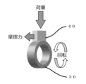
- a manganese phosphate coating containing copper specifically, there is a form in which the copper compound added during the formation of the manganese phosphate coating co-deposits in the manganese phosphate coating as shown in FIG.
- the manganese content (content based on the unit area of the coating) is 1.5 g/m 2 or more, preferably 1.7 g/m 2 or more, more preferably , 2.0 g/m 2 or more, or 2.1 g/m 2 or more.
- the manganese content in the manganese phosphate coating is more preferably 2.3 g/m 2 or more, more preferably 2.5 g/m 2 or more, and more preferably 3.0 g/m 2 or more. Especially preferred. Regarding the content of manganese in the manganese phosphate coating, the lower limit is important, and the upper limit is not particularly limited. It may be 8.0 g/m 2 or less. In the manganese phosphate coating, the value of the content ratio (weight ratio) of copper/manganese, that is, the ratio of the content of copper and manganese per unit area contained in the manganese phosphate coating is from 0.02 to 0.02.
- the content ratio (weight ratio) of copper/manganese is 0.02 or more, preferably 0.05 or more, 0.10 or more, or 0.15 or more, more preferably 0.20 or more, or 0.22 or more. , or greater than or equal to 0.25.
- the value of the content ratio of copper/manganese is 2.56 or less, preferably 2.20 or less, 2.00 or less, or 1.80 or less, more preferably 1.60 or less, 1.40 less than or equal to 1.30.
- the content ratio (weight ratio) of copper/manganese in the manganese phosphate coating is preferably in the range of 0.04 to 0.62.
- the content ratio value is preferably in the range of 0.06 to 0.50, more preferably in the range of 0.08 to 0.40, and in the range of 0.10 to 0.30 more preferably within.
- Phosphate coatings other than manganese phosphate coatings may be used, and specific examples thereof include zinc phosphate coatings, zinc calcium phosphate coatings, manganese phosphate coatings as well as manganese-containing phosphate coatings. zinc-manganese coating;
- the phosphate coating containing a metal other than manganese phosphate and copper co-deposit as in the manganese phosphate coating.
- the content of the phosphate-derived metal in the phosphate coating and the range of the weight ratio of the phosphate-derived metal to copper are the same as in the manganese phosphate coating described above. That is, in the phosphate coating containing metals other than manganese, the total content of phosphate-derived metals is preferably 2.1 g/m 2 or more, and preferably 2.3 g/m 2 or more. is more preferably 2.5 g/m 2 or more, and particularly preferably 3.0 g/m 2 or more.
- the lower limit is important, and the upper limit is not particularly limited, but for example, 15 g/ m2 or less. , 12 g/m 2 or less, 10 g/m 2 or less, or 8.0 g/m 2 or less.
- the content ratio (weight ratio) of the total amount of copper/phosphate-derived metal is, for example, 0.02 to 2.56, preferably 0.05 to 2.20, 0.10 to 2.00 or 0.15 to 1.80, more preferably 0.20 to 1.60, 0.22 to 1.40 or 0.25 to 1 .30.
- the value of the content ratio (weight ratio) of the total amount of copper/phosphate-derived metals is, for example, 0.02 or more, preferably 0.05 or more, 0.10 or more, or 0.15 or more, more preferably is greater than or equal to 0.20, greater than or equal to 0.22, or greater than or equal to 0.25.
- the value of the content ratio (weight ratio) of the total amount of copper/phosphate-derived metals is, for example, 2.56 or less, preferably 2.20 or less, 2.00 or less, or 1.80 or less. and more preferably 1.60 or less, 1.40 or less, or 1.30 or less.
- the value of the content ratio (weight ratio) of the total amount of copper/phosphate-derived metals in the phosphate coating is preferably in the range of 0.04 to 0.62.
- the weight ratio range is preferably in the range of 0.06 to 0.50, more preferably in the range of 0.08 to 0.40, and in the range of 0.10 to 0.30. It is even more preferable to have
- the manganese phosphate coating contains copper co-deposited with the formation of the manganese phosphate coating, and various phosphates are included as other components. It may be
- the phosphate coating is preferably a manganese phosphate coating, but may be a zinc phosphate coating or a zinc calcium phosphate coating. However, from the viewpoint of improving the adhesion and slidability of the phosphate coating, it is preferable to use a manganese phosphate coating or a zinc manganese phosphate coating.
- a copper-containing phosphate coating is formed with various phosphate solutions.
- manganese phosphate-based treatment agents, zinc phosphate-based treatment agents, zinc calcium phosphate-based treatment agents, and zinc manganese phosphate-based treatment agents are preferably used (for example, phosphorus
- a copper-containing phosphate film is formed by a mixed treatment solution in which a compound containing copper ions is added to a treatment solution that has been appropriately adjusted using manganese acid treatment agents such as PF-M1A and PF-M5). is formed.
- the phosphate solution preferably contains the following compound as a copper ion supply source for codepositing copper together with the phosphate. That is, examples of the copper ion supply source include copper (II) nitrate, aqueous solutions of copper (I) chloride, copper (II) chloride, copper (II) sulfate, metallic copper, and the like.
- a copper-containing phosphate coating may be formed by adding to the phosphating solution described above and using the added treating solution. The copper-containing phosphate coating is formed by, for example, immersing the second sliding component, which has been subjected to pretreatments such as cleaning and degreasing, in the mixed treatment liquid described above by a general method.
- the value of the copper/manganese weight ratio is 0.02 to 2.56, preferably 0.04 to 0.62.
- the value of the weight ratio of the total amount of metals is also preferably adjusted within the range of 0.02 to 2.56, preferably 0.04 to 0.62. Therefore, the content of the copper ion source contained in the phosphate solution is appropriately adjusted so that the weight ratio range can be achieved.
- Additives such as sources of metals nobler than iron, such as tin, lead, silver, and gold, are added to the phosphate solution in conjunction with or in place of the copper ion sources described above. good too.
- a resin-based additive may be used together with the metal (metal ion) supply source such as copper, or instead of the metal (metal ion) supply source. That is, fluorine-based resins (such as polytetrafluoroethylene) and polyolefin-based resins (such as polyethylene) that can be dispersed in a solution that is mainly an aqueous solution can also be used.
- the weight ratio of the total of the additive-derived components derived from the above-described copper ion source and the like used as an additive to the phosphate-derived metal such as manganese is also preferably 0. It is preferably adjusted within the range of 0.02 to 2.56, more preferably 0.04 to 0.62. Therefore, the total content of the additives contained in the phosphate solution is also appropriately adjusted so that the range of the weight ratio in the phosphate coating can be achieved.
- the thickness of the phosphate coating such as the manganese phosphate coating is appropriately adjusted depending on the use of the sliding member, and is, for example, 1 ⁇ m to 25 ⁇ m. Below is.
- the thickness of the phosphate coating is preferably 2 ⁇ m or more and 20 ⁇ m or less, more preferably 3 ⁇ m or more and 15 ⁇ m or less, and particularly preferably 4 ⁇ m or more and 10 ⁇ m or less.
- the wear depth is preferably 50 ⁇ m or less, preferably 40 ⁇ m or less, and 30 ⁇ m or less in a sliding performance test described later in detail. is more preferable, and 25 ⁇ m or less is particularly preferable.
- a baked coating containing a solid lubricant may be formed on the phosphate coating such as the manganese phosphate coating.
- the phosphate coating such as the manganese phosphate coating.
- it is a fired film containing an organic binder, a curing agent, a solid lubricant, and the like.
- a sintering process is required to heat the material such as the sintered film, and depending on the sintering process, carbon dioxide, which is a greenhouse gas, is also emitted. . Therefore, if only a phosphate film containing a predetermined component such as copper is provided by a simple method as described above, it is possible to improve the efficiency of the manufacturing process and reduce the generation of greenhouse gases.
- Both the first and second sliding parts can be manufactured based on known techniques.
- the value of the surface roughness Ra of the first sliding surface is measured by a method described in detail below in order to confirm whether the surface roughness Ra of the first sliding surface is adjusted within a predetermined range. is preferred. Then, when the value of the surface roughness Ra is out of the predetermined range, the surface roughness is adjusted by a known method such as lathe turning.
- a phosphate coating is formed, for example, by the method described above.
- the combined sliding member described above is used in various applications, and can be widely used particularly in members made of a combination of aluminum and steel materials.
- the parts in which the first sliding part containing aluminum or aluminum alloy/second sliding part containing steel material can be used include valves/valve bodies, rocker arms/rocker shafts, pistons/piston rings, pistons/pistons, Pins, pistons/cylinders, housings/bearings (eg, rolling bearings, slide bearings, etc.), electric steering columns (case housings (aluminum)/pipes (eg, steel tubes for mechanical structures (STKM), etc.)).
- a preferred combination of the above-described first sliding component/second sliding component that is, a preferred form of the combined sliding member includes a housing and a bearing, such as a housing and a rolling bearing.
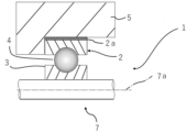
- An example of a combined housing and bearing sliding member is shown schematically in the partial cross-sectional view of FIG. In FIG. 3 the combined sliding member comprising the rolling bearing 1 and the housing 5 is installed in a rotating device with a rotating member 7 .
- the rolling bearing 1 is preferably made of a steel material such as SUJ material such as SUJ2, SCr material, SCM material, or SNCM material, and the housing 5 is preferably made of an aluminum alloy.
- a rolling bearing 1 includes an outer ring 2 , an inner ring 3 , and a plurality of rolling elements (balls) 4 interposed between the outer ring 2 and the inner ring 3 .
- the rolling bearing 1 holds a rotating shaft member 7 that rotates around a rotating shaft 7a.
- one of the outer ring 2 and the inner ring 3 is a rotating ring, and the other is a stationary ring.
- a manganese phosphate coating 2a containing copper is formed on the surface of the fixed ring, for example, the outer ring 2, which contacts the housing 5.
- the coating may be provided only on the top surface of the outer diameter surface, which is the surface of the outer ring 2, which is the fixed ring, and which is the surface on the housing side.
- the side surface in contact with the housing 5 in FIG. 3, the surface on the lower left of the top surface where the coating 2a is provided
- the coating may be provided, and preferably, the coating is provided on the entire region of the sliding surface of the outer diameter surface of the outer ring 2 that slides against the housing 5 .
- the outer ring rotating type bearing may be provided with a copper-containing manganese phosphate coating.
- a copper-containing manganese phosphate coating is formed on at least a portion of the inner diameter surface of the inner ring.
- the manganese phosphate coating may be provided only on a partial region of the sliding surface of the inner diameter surface of the inner ring that slides against the housing. It is preferable that the coating is provided over the entire area of the surface.
- the surface roughness Ra is adjusted to 2.9 ⁇ m or less in the region in contact with the fixed ring such as the outer ring 2 .
- the combination sliding member on which the manganese phosphate coating is formed also includes rolling bearings other than the ball bearings, such as roller bearings.
- rolling bearings other than the ball bearings, such as roller bearings.
- sliding members provided with a manganese phosphate coating include thrust ball bearings, angular contact ball bearings, deep groove ball bearings, self-aligning ball bearings, cylindrical roller bearings, tapered roller bearings, needle roller bearings, and self-aligning roller bearings.
- thrust cylindrical roller bearings, thrust tapered roller bearings, thrust needle roller bearings, thrust self-aligning roller bearings, etc., and other bearings may be coated with manganese phosphate.
- the rolling bearing as a combined sliding member is suitably used as, for example, vehicle transmissions, bearings for various motors, and the like.
- a treatment solution for a copper-containing manganese phosphate coating was prepared by the method described below. That is, a manganese phosphate-based treatment agent (PF-M5: manufactured by Nihon Parkerizing Co., Ltd.) and copper (II) nitrate were blended so as to obtain each coating component of Examples 1 to 7 and Comparative Example 3 in Table 1 below. An aqueous solution was obtained by appropriately adjusting the ratio and mixing them. That is, a copper-added manganese phosphate treatment liquid was prepared for forming a manganese phosphate film on the surface of the steel material in the combined sliding member.
- PF-M5 manufactured by Nihon Parkerizing Co., Ltd.
- copper (II) nitrate were blended so as to obtain each coating component of Examples 1 to 7 and Comparative Example 3 in Table 1 below.
- An aqueous solution was obtained by appropriately adjusting the ratio and mixing them. That is, a copper-added manganese phosphate treatment liquid was prepared for forming a manganes
- a ring-shaped steel material having a copper-containing manganese phosphate film was obtained by immersing it in the manganese phosphate treatment solution under conditions of a treatment temperature of 90° C. and a treatment time of 10 minutes.
- Examples 2 to 7, Comparative Example 3 A copper-added manganese phosphate treatment solution having a composition different from that of Example 1 was used so that the film components described in the columns of Examples 2 to 7 and Comparative Example 3 in Table 1 below were obtained. A ring-shaped steel material having a copper-containing manganese phosphate coating was obtained in the same manner as in 1.
- Comparative Examples 1 and 2 and Reference Example In Comparative Example 1, only the ring-shaped steel material made of the same SUJ2 as in Example 1 was used for the evaluation test without forming the manganese phosphate coating.
- a manganese phosphate treatment solution containing no copper (II) nitrate was immersed at a treatment temperature of 85 to 90° C. for a treatment time of 10 minutes, and copper was added in the same manner as in Example 1.
- a ring-shaped steel material having a manganese phosphate coating was obtained.
- a ring-shaped steel material was obtained in which a polymer resin layer containing molybdenum disulfide and graphite as solid lubricants was formed after forming a copper-free manganese phosphate coating.
- Comparative Example 4 a ring-shaped steel material was obtained in which a copper plating film was formed by electrolytic copper plating instead of the manganese phosphate treatment film.
- the block material that contacts the outer peripheral surface of the ring-shaped steel material As shown in Table 1 below, samples having a surface roughness of 0.4 ⁇ m, 1.6 ⁇ m, 2.0 ⁇ m or 3.0 ⁇ m were prepared.
- the film thicknesses of various coatings of each example, comparative example and reference example were measured as follows. A steel sample having a film formed on its surface was cut perpendicularly to the film, the cut sample was embedded in resin, hardened, and scraped with abrasive paper to expose the cross section of the film. The sample whose cross section was mirror-finished in this way was observed under an enlarged scanning electron microscope to measure the film thickness. Observation conditions of the scanning electron microscope are shown below. SEM magnification observation measurement conditions Tester: Electron microscope JSM-6510LA manufactured by JEOL Ltd. Accelerating voltage: 15 kV Detected electrons: Reflected electrons Observation magnification: 2000 times
- Film thickness was measured by magnified observation of a scanning electron microscope as follows. The distance between two points facing each other on the coating in the enlarged observation image, that is, the two points on the virtual line perpendicular to the coating surface is measured at five points included in one field of view, and the average value of the distance values was calculated and used as the film thickness value of the coating (see FIG. 1). That is, as shown in FIG. 1, a sample in which a copper-containing manganese phosphate coating 12 is formed on the surface of a steel material 10 is embedded in an embedding resin 22, and then the cross section of the exposed sample is observed. The film thickness of the coating 12 was measured.
- the amount of Mn and Cu in each coating was measured by fluorescent X-ray measurement for various coatings of each example and comparative example.
- the conditions for the fluorescent X-ray measurement are as follows. Testing machine: Fluorescent X-ray analyzer RIX2100 manufactured by Rigaku Corporation Measurement conditions: voltage value 50 kV Current value 50mA Measurement diameter ⁇ 10mm
- the content of Cu and Mn in the film was measured by fluorescent X-ray under the above conditions as follows.
- a calibration curve is prepared in advance from the X-ray intensity of each component in the coating of each component and the coating analysis results by ICP-AES by wet peeling, and each example and comparative example that is an unknown sample is based on the created calibration curve.
- Quantitative analysis of each component in the coating was performed. Table 1 shows the amount of Mn (g/m 2 ), the amount of Cu (g/m 2 ), and the content ratio of Cu/Mn in the film thus confirmed.
- the method for measuring the content of Cu and Mn in the coating is not limited to the above-described measurement method using fluorescent X-rays, and the content of each component of Cu and Mn may be measured by other methods.
- the content of each component in the film may be measured using a technique such as atomic absorption spectrometry (AAS) by wet peeling or ICP emission spectrometry (ICP-AES).
- AAS atomic absorption spectrometry
- ICP-AES ICP emission spectrometry
- LFW-1 test sliding performance test (wear resistance: LFW-1 test)
- LFW-1 test was conducted.
- an aluminum block whose surface roughness Ra was previously confirmed was placed on the surface of the steel rings of each example and comparative example on which various coatings were formed except for Comparative Example 1.
- the steel ring was rotated while applying a load from above the aluminum block (see Fig. 2).
- the conditions for the LFW-1 test are as follows. Tester Falex block-on-ring friction wear tester (LFW-1) Rotation speed 100rpm Load 112-787LBS (Increase by 112.4LBS per step) Test time 1 step/min x 7 steps Lubrication environment Nissan genuine CVTF NS-3
- the results of the measured wear amount are shown in the aluminum block wear amount column of Table 1 above.
- Table 1 the amount of aluminum wear was evaluated as good when 0 to less than 40 ⁇ m, somewhat poor when 40 ⁇ m or more and less than 100 ⁇ m, and poor when 100 ⁇ m or more. Further, as is clear from Table 1 showing the results of Examples 3, 6, 7, Comparative Example 3, etc., in which only the value of the surface roughness Ra on the sliding surface of the aluminum block is different, the sliding It was also confirmed that the amount of wear was remarkably low when the surface roughness Ra of the surface was in the range of 0.4 to 2.0 ⁇ m (see Table 1).
- Example 9 to 12 Comparative Examples 5 and 6
- a copper-added manganese phosphate treatment solution having a composition different from that of Example 8 was used so as to obtain the film components described in the columns of Examples 9 to 12, Comparative Examples 5 and 6 in Table 2 below. Otherwise, in the same manner as in Example 8, a ring-shaped steel material having a copper-containing manganese phosphate coating was obtained.
- Examples 8 to 12 and Comparative Examples 5 and 6 were evaluated in the same manner as in Examples 1 to 7, Comparative Examples 1 to 4, and Reference Example. That is, for Examples 8 to 12 and Comparative Examples 5 and 6, the film thickness was measured, the Ra value of the aluminum block material was measured, the Cu and Mn contents in the film (sliding surface) were measured, and the sliding surface was measured. A dynamic performance test (wear resistance: LFW-1 test) and an amount of wear of the aluminum block (result of LFW-1 test) were measured. Table 2 shows the results.
Abstract
The present invention addresses the problem of providing a combination sliding member which has low impact on the environment, which can be produced via a simple method, and which has excellent antifriction properties and durability. This problem is solved by a combination sliding member. Specifically, the problem is solved by a combination sliding member comprising a first sliding part that is made from aluminum or an aluminum alloy and a second sliding part that is made from a steel material, said combination sliding member being characterized in that: a surface of the second sliding part that slides on the first sliding part has a manganese phosphate coating that contains copper; in the manganese phosphate coating, the manganese content is not less than 1.5 g/m2 and the copper/manganese content ratio is 0.02-2.56; and the surface roughness Ra of a surface of the first sliding part that slides on the second sliding part is not more than 2.9 μm.
Description
本発明は、摺動部材に関するものであり、特に、互いに摺動する複数の摺動部材を含む組み合わせ摺動部材に関する。組み合わせ摺動部材には、例えば、転がり軸受とハウジングなどが含まれる。
The present invention relates to a sliding member, and more particularly to a combination sliding member including a plurality of sliding members that slide against each other. Combination sliding members include, for example, rolling bearings and housings.
従来、例えば、バルブとバルブボディ等のように、硬度の異なる材料で形成された部材を含む組み合わせ摺動部材が利用されている。このような組み合わせ摺動部材として、たとえば、摺動面にアルマイト層が形成されているアルミニウム合金からなる第1摺動部品と、該第1摺動部品の摺動面に摺動し、所定の高分子樹脂、強化繊維および固体潤滑剤からなる第2摺動部品とを備えた組み合わせ摺動部材(特許文献1)などが知られている。
Conventionally, a combination sliding member including members formed of materials with different hardness, such as a valve and a valve body, has been used. As such a combined sliding member, for example, a first sliding component made of an aluminum alloy having an alumite layer formed on the sliding surface, and a sliding surface of the first sliding component that slides on the sliding surface to provide a predetermined A combined sliding member (Patent Document 1) is known that includes a second sliding component made of polymer resin, reinforcing fibers, and solid lubricant.
また、省エネルギー化の観点から様々な産業分野において機器の小型化が求められており、これに伴って例えば、転がり軸受とハウジングの組合せ摺動部材における軸受は薄肉化される傾向にある。そして薄肉化された軸受、例えば転がり軸受などにおいて、摺動環境によっては外輪などの固定側部品がハウジングに対して回転するクリープ現象が生じる可能性がある。クリープ現象はハウジングの摩耗を進行させ、回転機器の不具合を生じさせ得る。
In addition, from the viewpoint of energy saving, there is a demand for downsizing of equipment in various industrial fields, and along with this, for example, there is a tendency for bearings in sliding members that combine rolling bearings and housings to be thinner. In thin-walled bearings such as rolling bearings, there is a possibility that a creep phenomenon may occur in which a fixed side component such as an outer ring rotates with respect to a housing depending on the sliding environment. The creep phenomenon accelerates housing wear and can cause failure of rotating equipment.
上述の従来技術のように、固体潤滑剤等を含む高分子樹脂の層を形成するためには、焼成工程が必要である。このため、昨今、対策が必要とされている地球温暖化の観点から、ライフサイクルアセスメントにおける温室効果ガスの発生量の削減という課題がある。
例えば、転がり軸受とハウジングの組合せ摺動部材などにおけるクリープ現象に伴うハウジングの摩耗の防止のために、ハウジングと接する摺動面に固体潤滑剤等を含有する高分子樹脂層を形成するには、焼成工程が必要となり、軸受の製造工程が煩雑となる上に温室効果ガスを生じさせてしまう。
また、特許文献1に示されているようにアルマイト層を形成するためには、酸性の処理液を用いる陽極酸化処理などのように比較的、煩雑な工程が必要となり、また、電力消費が増加する。 As in the prior art described above, a sintering step is required to form a layer of polymeric resin containing a solid lubricant or the like. Therefore, from the viewpoint of global warming, for which countermeasures are required these days, there is a problem of reducing the amount of greenhouse gases generated in the life cycle assessment.
For example, in order to prevent abrasion of the housing due to creep phenomenon in a sliding member combining a rolling bearing and a housing, a polymer resin layer containing a solid lubricant or the like is formed on the sliding surface in contact with the housing. A firing process is required, which complicates the manufacturing process of the bearing and produces greenhouse gases.
In addition, in order to form an alumite layer as shown inPatent Document 1, a relatively complicated process such as an anodizing treatment using an acidic treatment liquid is required, and power consumption increases. do.
例えば、転がり軸受とハウジングの組合せ摺動部材などにおけるクリープ現象に伴うハウジングの摩耗の防止のために、ハウジングと接する摺動面に固体潤滑剤等を含有する高分子樹脂層を形成するには、焼成工程が必要となり、軸受の製造工程が煩雑となる上に温室効果ガスを生じさせてしまう。
また、特許文献1に示されているようにアルマイト層を形成するためには、酸性の処理液を用いる陽極酸化処理などのように比較的、煩雑な工程が必要となり、また、電力消費が増加する。 As in the prior art described above, a sintering step is required to form a layer of polymeric resin containing a solid lubricant or the like. Therefore, from the viewpoint of global warming, for which countermeasures are required these days, there is a problem of reducing the amount of greenhouse gases generated in the life cycle assessment.
For example, in order to prevent abrasion of the housing due to creep phenomenon in a sliding member combining a rolling bearing and a housing, a polymer resin layer containing a solid lubricant or the like is formed on the sliding surface in contact with the housing. A firing process is required, which complicates the manufacturing process of the bearing and produces greenhouse gases.
In addition, in order to form an alumite layer as shown in
本発明はこのような点に鑑みてなされたものであり、本発明によれば、環境負荷が低く、簡便な方法によって製造可能であるとともに、耐摩耗性、耐久性等に優れた組み合わせ摺動部材、例えば、転がり軸受のクリープに伴うハウジング摩耗を抑制可能な組合せ摺動部材などを提供できる。
The present invention has been made in view of these points, and according to the present invention, a combined sliding surface that has low environmental load, can be manufactured by a simple method, and is excellent in wear resistance, durability, etc. It is possible to provide a member, for example, a combined sliding member capable of suppressing housing wear due to rolling bearing creep.
本発明により上述の課題は解決された。本発明は、以下に記載のものを含む。
[1]アルミニウム又はアルミニウム合金からなる第1摺動部品と、鋼材からなる第2摺動部品とを備えた組み合わせ摺動部材であって、
前記第2摺動部品における前記第1摺動部品と摺動する面が、銅を含有するりん酸マンガン被膜を有し、前記りん酸マンガン被膜において、マンガンの含有量が1.5g/m2以上であり、銅/マンガン含有量比率が0.02~2.56であり、
前記第1摺動部品における前記第2摺動部品と摺動する面の表面粗さRaが2.9μm以下であることを特徴とする組み合わせ摺動部材。
[2]前記第1摺動部品/前記第2摺動部品としてのバルブ/バルブボディ、ロッカーアーム/ロッカーシャフト、ピストン/ピストンリング、ピストン/ピストンピン、ピストン/シリンダー、ハウジング/軸受及びステアリング電動コラム/パイプのいずれかである、上記[1]に記載の組み合わせ摺動部材。
[3]前記第1摺動部品がハウジングであり、前記第2摺動部品が転がり軸受である、上記[2]に記載の組み合わせ摺動部材。
[4]前記第2摺動部品としての前記転がり軸受が、
外輪と、内輪と、前記外輪及び前記内輪との間に転動自在に配設される複数の転動体とを備え、
前記外輪の外径面及び前記内輪の内径面の少なくとも一方であって、前記第1摺動部品としてのハウジングに摺動する面が前記りん酸マンガン被膜を有する、上記[3]に記載の組み合わせ摺動部材。
[5]アルミニウム又はアルミニウム合金からなる第1摺動部品と、鋼材からなる第2摺動部品とを備えた組み合わせ摺動部材であって、
前記第2摺動部品における前記第1摺動部品と摺動する面が、銅を含有するりん酸マンガン被膜を有し、前記りん酸マンガン被膜において、マンガンの含有量が2.1g/m2以上であり、銅/マンガン含有量比率が0.04~0.62であり、
前記第1摺動部品における前記第2摺動部品と摺動する面の表面粗さRaが2.9μm以下であることを特徴とする組み合わせ摺動部材。
[6]前記第2摺動部品が、JIS G4805:2008にて定められるSUJ材である、上記[5]に記載の組み合わせ摺動部材。
[7]前記りん酸マンガン被膜の厚さが1~25μmである、上記[1]又は[5]に記載の組み合わせ摺動部材。 The above problems have been solved by the present invention. The present invention includes the following.
[1] A combined sliding member comprising a first sliding component made of aluminum or an aluminum alloy and a second sliding component made of steel,
A surface of the second sliding part that slides against the first sliding part has a copper-containing manganese phosphate coating, and the manganese phosphate coating contains 1.5 g/m 2 of manganese. above, the copper/manganese content ratio is 0.02 to 2.56,
A combination sliding member, wherein a surface roughness Ra of a surface of the first sliding part that slides on the second sliding part is 2.9 μm or less.
[2] Valves/valve bodies, rocker arms/rocker shafts, pistons/piston rings, pistons/piston pins, pistons/cylinders, housings/bearings, and electric steering columns as the first sliding parts/second sliding parts / The combination sliding member according to the above [1], which is either a pipe.
[3] The combined sliding member according to [2] above, wherein the first sliding component is a housing and the second sliding component is a rolling bearing.
[4] The rolling bearing as the second sliding component is
An outer ring, an inner ring, and a plurality of rolling elements arranged to be rollable between the outer ring and the inner ring,
The combination according to [3] above, wherein at least one of the outer diameter surface of the outer ring and the inner diameter surface of the inner ring, the surface sliding on the housing as the first sliding component has the manganese phosphate coating. sliding member.
[5] A combined sliding member comprising a first sliding component made of aluminum or an aluminum alloy and a second sliding component made of steel,
A surface of the second sliding part that slides on the first sliding part has a copper-containing manganese phosphate coating, and the manganese phosphate coating has a manganese content of 2.1 g/m 2 . above, the copper/manganese content ratio is 0.04 to 0.62,
A combination sliding member, wherein a surface roughness Ra of a surface of the first sliding part that slides on the second sliding part is 2.9 μm or less.
[6] The combined sliding member according to [5] above, wherein the second sliding component is an SUJ material defined in JIS G4805:2008.
[7] The combined sliding member according to [1] or [5] above, wherein the manganese phosphate coating has a thickness of 1 to 25 μm.
本発明によれば、環境負荷が低く、簡便な方法によって、耐摩耗性、耐久性等に優れた組み合わせ摺動部材を提供できる。
According to the present invention, it is possible to provide a combination sliding member that has a low environmental load and is excellent in wear resistance, durability, etc., by a simple method.
以下、本発明について、詳細に説明する。
The present invention will be described in detail below.
[1.摺動部材]
本発明の組み合わせ摺動部材は、少なくとも第1摺動部品と第2摺動部品とを含む、第1摺動部品と第2摺動部品とは、互いの摺動面が接して摺動するように構成されている。
以下、各部材について説明する。 [1. Sliding member]
The combined sliding member of the present invention includes at least a first sliding component and a second sliding component, wherein the sliding surfaces of the first sliding component and the second sliding component are in contact with each other and slide. is configured as
Each member will be described below.
(1-1.第1摺動部品)
1-1a.第1摺動部品の材質
第1摺動部品は、アルミニウム及びアルミニウム合金からなる。第1摺動部品に含まれるアルミニウム及びアルミニウム合金の具体例として、JIS H4000:2017にて定められている以下の合金記号のものが挙げられる。
すなわち、1085,1080,1070,1060,1050,1100,1200,1N00,1N30,1230,2014,2017,2219,2024,2124,3003,3103,3203,3004,3104,3005,3105,3003,5005,5052,5110,5021,5042,5050,5052,5154,5254,5454,5754,5456,5082,5182,5083,5086,5N01,6101,6061,6082,7204,7N01,7204,7010,7050,7075,7072,7475,7178,8011,8021,8079等の合金記号で表されるものである。
また、第1摺動部品に含まれるアルミニウム及びアルミニウム合金の具体例には、JIS H5302:2006、JISH5202:2010などの日本産業規格におけるJIS記号のうち、AC1B、AC1C、AC2A、AC2B、AC3A、AC4A、AC4B、AC4C、AC4CH、AC4D、AC5A、AC7A、AC8A、AC8B、AC8C、AC9A、AC9B、ADC1,ADC3,ADC5,ADC6,ADC10,ADC10Z,ADC12,ADC12Z,ADC14で表されるものが含まれる。 (1-1. First sliding component)
1-1a. Material of First Sliding Part The first sliding part is made of aluminum or an aluminum alloy. Specific examples of aluminum and aluminum alloys contained in the first sliding component include the following alloy symbols defined in JIS H4000:2017.
In other words, 1085, 1080, 1060, 1060 ,1050 ,1200, 1N00, 1N00, 1N30, 1230, 2017, 2017, 2219, 2219, 2219, 2219, 3103, 3203, 3204, 3104, 3105, 3003, 3003, 3003, 3003, 3003, 3003, 3003, 3003, 3003. 5, 5052, 5110, 5021, 5042, 5050, 5052, 5154, 5254, 5454, 5754, 5456, 5082, 5182, 5083, 5086, 5N01, 6101, 6061, 6082, 7204, 7N01, 7204, 7010, 7050, 7 075, It is represented by an alloy symbol such as 7072, 7475, 7178, 8011, 8021, 8079.
Further, specific examples of aluminum and aluminum alloys contained in the first sliding part include AC1B, AC1C, AC2A, AC2B, AC3A, and AC4A among JIS symbols in Japanese Industrial Standards such as JIS H5302:2006 and JISH5202:2010. , AC4B, AC4C, AC4CH, AC4D, AC5A, AC7A, AC8A, AC8B, AC8C, AC9A, AC9B, ADC1, ADC3, ADC5, ADC6, ADC10, ADC10Z, ADC12, ADC12Z, and ADC14.
上述のアルミニウム、アルミニウム合金のうち、いずれか1種のみが第1摺動部品に含まれていてもよく、複数以上のものが含まれていてもよい。
The first sliding component may contain only one of the aluminum and aluminum alloys described above, or may contain more than one.
1-1b.第2摺動部品と摺動する面(第1摺動面)
第1摺動部品は、第2摺動部品に接している摺動面(第1の摺動面)を有する。第1の摺動面においては、表面粗さが調整されている。
すなわち、第1の摺動面におけるJIS B 0601-2001に準拠した算術平均粗さRaの値は、2.9μm以下である。また、第1の摺動面におけるRaの値は、好ましくは2.5μm以下であり、より好ましくは2.2μm以下であり、さらに好ましくは2.0μm以下であり、特に好ましくは1.8μm以下、1.5μm以下、1.2μm以下、1.0μm以下、あるいは0.8μm以下である。 1-1b. Surface that slides with the second sliding component (first sliding surface)
The first sliding component has a sliding surface (first sliding surface) in contact with the second sliding component. The surface roughness is adjusted on the first sliding surface.
That is, the value of the arithmetic mean roughness Ra conforming to JIS B 0601-2001 on the first sliding surface is 2.9 μm or less. In addition, the Ra value of the first sliding surface is preferably 2.5 μm or less, more preferably 2.2 μm or less, still more preferably 2.0 μm or less, and particularly preferably 1.8 μm or less. , 1.5 μm or less, 1.2 μm or less, 1.0 μm or less, or 0.8 μm or less.
第1の摺動面における表面粗さは小さいことが好ましいため、Ra値の下限値は特に重要ではないものの、第1の摺動面におけるRaの値は、例えば、0.1μm以上、0.2μm以上、0.3μm以上、あるいは0.4μm以上である。
なお、算術平均粗さRaの値の測定方法については後述する。 Since it is preferable that the surface roughness of the first sliding surface is small, the lower limit of the Ra value is not particularly important. It is 2 μm or more, 0.3 μm or more, or 0.4 μm or more.
A method for measuring the value of the arithmetic mean roughness Ra will be described later.
(1-2.第2摺動部品)
1-2a.第2摺動部品の材質
第2摺動部品は、少なくとも鋼材を含む。第2摺動部品に含まれる鋼材の具体例として、JIS G4805:2008などの日本産業規格にて定められている鉄鋼基材料記号SUJ1,SUJ2,SUJ3,SUJ4,SUJ5(SUJ材:高炭素クロム軸受鋼鋼材),SCr415,SCr420,SCr435(SCr材:クロム鋼鋼材),SCM415,SCM418,SCM420,SCM421,SCM425,SCM430,SCM432,SCM435,SCM440,SCM445,SCM822(SCM材:クロムモリブデン鋼鋼材),SNCM220,SNCM420,SNCM815(SNCM材:ニッケルクロムモリブデン鋼鋼材),SUS440,SUS403,SUS410,SUS410J1,SUS410F2,SUS416,SUS420J1,SUS420J2,SUS420F,SUS420F2,SUS431,SUS440A,SUS440B,SUS440C,SUS440F,SUS405,SUS410L,SUS430,SUS430F,SUS434,SUS447J1,SUSXM27,SUS329J1,SUS329J3L,SUS329J4L,SUS201,SUS202,SUS301,SUS302,SUS303,SUS303Se,SUS303Cu,SUS304,SUS304L,SUS304N1,SUS304N2,SUS304LN,SUS304J3,SUS305,SUS309S,SUS310S,SUS316,SUS316L,SUS316N,SUS316LN,SUS316Ti,SUS316J1,SUS316J1L,SUS316F,SUS317,SUS317L,SUS317LN,SUS317J1,SUS836L,SUS890L,SUS321,SUS347,SUSXM7,SUSXM15J1,SUS631等で表されるもの、上記JIS規格に概ね対応するAISI等の他の規格で規定されるものなどが挙げられる。
上述の鋼材は、第2摺動部品の種類にかかわらず採用され得るが、例えば、転がり軸受などの軸受において好適に用いられる。
第2摺動部品に含まれる鋼材のさらなる具体例として、炭素鋼、冷間圧延鋼板(SPCC),機械構造用炭素鋼鋼管(STKM材),炭素工具鋼(SK材),合金工具鋼(SKS材)、機械構造部品用焼結材料、その他の構造用特殊鋼なども挙げられる。これらの鋼材も、第2摺動部品の種類にかかわらず採用され得るが、例えば、軸受以外の部品などで好適に用いられる。 (1-2. Second sliding component)
1-2a. Material of Second Sliding Part The second sliding part contains at least steel. As a specific example of the steel material contained in the second sliding part, steel base material symbols SUJ1, SUJ2, SUJ3, SUJ4, SUJ5 (SUJ material: high carbon chromium bearing steel material), SCr415, SCr420, SCr435 (SCr material: chrome steel material), SCM415, SCM418, SCM420, SCM421, SCM425, SCM430, SCM432, SCM435, SCM440, SCM445, SCM822 (SCM material: chromium molybdenum steel material), SNCM220 , SNCM420, SNCM815 (SNCM material: nickel-chromium-molybdenum steel), SUS440, SUS403, SUS410, SUS410J1, SUS410F2, SUS416, SUS420J1, SUS420J2, SUS420F, SUS420F2, SUS431, SUS440A, SUS440B, SUS4 40C, SUS440F, SUS405, SUS410L, SUS430 , SUS430F, SUS434, SUS447J1, SUSXM27, SUS329J1, SUS329J3L, SUS329J4L, SUS201, SUS202, SUS301, SUS302, SUS303, SUS303Se, SUS303Cu, SUS304, SUS304L, SUS304N1, SUS304N2, SUS304LN, SUS304J3, SUS305, SUS309S, SUS310S, SUS316, SUS316L , SUS316N, SUS316LN, SUS316Ti, SUS316J1, SUS316J1L, SUS316F, SUS317, SUS317L, SUS317LN, SUS317J1, SUS836L, SUS890L, SUS321, SUS347, SUSXM7, SUSXM15J1, SUS63 Those represented by 1 etc., AISI etc. that generally correspond to the above JIS standards and those stipulated by other standards.
The steel material described above can be used regardless of the type of the second sliding component, and is preferably used in bearings such as rolling bearings, for example.
Further specific examples of the steel material contained in the second sliding part include carbon steel, cold-rolled steel plate (SPCC), carbon steel pipe for machine structural use (STKM material), carbon tool steel (SK material), alloy tool steel (SKS materials), sintered materials for machine structural parts, and other structural special steels. These steel materials can also be employed regardless of the type of the second sliding component, and are preferably used for components other than bearings, for example.
また、第2摺動部品の鋼材においては、所定の熱処理、例えば、焼入れ及び焼戻し処理、浸炭又は浸炭窒化処理と焼入れ及び焼戻し処理等が施されていてもよい。
上述の鋼材のうち、いずれか1種のみが第2摺動部品に含まれていてもよく、複数以上のものが含まれていてもよい。 Further, the steel material of the second sliding part may be subjected to a predetermined heat treatment such as quenching and tempering, carburizing or carbonitriding, quenching and tempering.
The second sliding component may contain only one of the steel materials described above, or may contain more than one.
1-2b.銅含有のりん酸マンガン被膜(りん酸塩被膜)
第2摺動部品においては、第1摺動部品と接する摺動面(第2の摺動面)にて、銅を含むりん酸マンガン被膜が形成されている。りん酸マンガン被膜は、上述の第1の摺動面と接するように、第2の摺動面の表面に配置されている。 1-2b. Copper-containing manganese phosphate coating (phosphate coating)
A copper-containing manganese phosphate coating is formed on the sliding surface (second sliding surface) of the second sliding component that is in contact with the first sliding component. The manganese phosphate coating is arranged on the surface of the second sliding surface so as to be in contact with the first sliding surface.
りん酸マンガン被膜は、銅及びマンガンを含む。銅を含むりん酸マンガン被膜として、具体的には、りん酸マンガン被膜生成時に添加した銅化合物が、図1に示すようにりん酸マンガン被膜に共析している形態が挙げられる。そしてりん酸マンガン被膜においては、マンガンの含有量(被膜の単位面積を基準とした含有量)が1.5g/m2以上であり、好ましくは1.7g/m2以上であり、より好ましくは、2.0g/m2以上あるいは2.1g/m2以上である。
りん酸マンガン被膜におけるマンガンの含有量は、2.3g/m2以上であることがさらに好ましく、2.5g/m2以上であることがより好ましく、3.0g/m2以上であることが特に好ましい。
また、りん酸マンガン被膜におけるマンガンの含有量については、下限値が重要であり、上限値について特に制限はないが、例えば、15g/m2以下、12g/m2以下、10g/m2以下あるいは8.0g/m2以下であってもよい。
りん酸マンガン被膜においては、銅/マンガンの含有量比率(重量比)の値、すなわち、りん酸マンガン被膜に含まれる単位面積あたりの銅とマンガンの含有量の比の値が、0.02~2.56であり、好ましくは0.05~2.20、0.10~2.00あるいは0.15~1.80であり、より好ましくは0.20~1.60、0.22~1.40あるいは0.25~1.30である。
銅/マンガンの含有量比率(重量比)の値は、0.02以上、好ましくは0.05以上、0.10以上、あるいは0.15以上、より好ましくは0.20以上、0.22以上、あるいは0.25以上である。また、銅/マンガンの含有量比率の値は、2.56以下であり、好ましくは2.20以下、2.00以下あるいは1.80以下であり、より好ましくは1.60以下、1.40以下あるいは1.30以下である。
また、りん酸マンガン被膜における銅/マンガンの含有量比率(重量比)の値は、好ましくは、0.04~0.62の範囲内にある。当該含有量比率の値は、0.06~0.50の範囲内にあることが好ましく、0.08~0.40の範囲内にあることがより好ましく、0.10~0.30の範囲内にあることがさらに好ましい。 Manganese phosphate coatings contain copper and manganese. As a manganese phosphate coating containing copper, specifically, there is a form in which the copper compound added during the formation of the manganese phosphate coating co-deposits in the manganese phosphate coating as shown in FIG. In the manganese phosphate coating, the manganese content (content based on the unit area of the coating) is 1.5 g/m 2 or more, preferably 1.7 g/m 2 or more, more preferably , 2.0 g/m 2 or more, or 2.1 g/m 2 or more.
The manganese content in the manganese phosphate coating is more preferably 2.3 g/m 2 or more, more preferably 2.5 g/m 2 or more, and more preferably 3.0 g/m 2 or more. Especially preferred.
Regarding the content of manganese in the manganese phosphate coating, the lower limit is important, and the upper limit is not particularly limited. It may be 8.0 g/m 2 or less.
In the manganese phosphate coating, the value of the content ratio (weight ratio) of copper/manganese, that is, the ratio of the content of copper and manganese per unit area contained in the manganese phosphate coating is from 0.02 to 0.02. 2.56, preferably 0.05 to 2.20, 0.10 to 2.00 or 0.15 to 1.80, more preferably 0.20 to 1.60, 0.22 to 1 .40 or 0.25 to 1.30.
The content ratio (weight ratio) of copper/manganese is 0.02 or more, preferably 0.05 or more, 0.10 or more, or 0.15 or more, more preferably 0.20 or more, or 0.22 or more. , or greater than or equal to 0.25. In addition, the value of the content ratio of copper/manganese is 2.56 or less, preferably 2.20 or less, 2.00 or less, or 1.80 or less, more preferably 1.60 or less, 1.40 less than or equal to 1.30.
The content ratio (weight ratio) of copper/manganese in the manganese phosphate coating is preferably in the range of 0.04 to 0.62. The content ratio value is preferably in the range of 0.06 to 0.50, more preferably in the range of 0.08 to 0.40, and in the range of 0.10 to 0.30 more preferably within.
りん酸マンガン被膜以外のりん酸塩被膜を用いてもよく、その具体例として、りん酸亜鉛被膜、りん酸亜鉛カルシウム被膜、りん酸マンガン被膜と同様にマンガンを含むりん酸塩被膜であるりん酸亜鉛マンガン被膜などが挙げられる。
Phosphate coatings other than manganese phosphate coatings may be used, and specific examples thereof include zinc phosphate coatings, zinc calcium phosphate coatings, manganese phosphate coatings as well as manganese-containing phosphate coatings. zinc-manganese coating;
上述のようにマンガン以外の金属を含むりん酸塩被膜においても、りん酸マンガン被膜と同様に、りん酸塩と銅とが共析している。りん酸塩被膜におけるりん酸塩由来の金属の含有量、及び、銅に対するりん酸塩由来の金属の重量比の範囲は、上述のりん酸マンガン被膜の場合と同様である。
すなわち、マンガン以外の金属を含むりん酸塩被膜においては、りん酸塩由来の金属の合計の含有量が2.1g/m2以上であることが好ましく、2.3g/m2以上であることがより好ましく、2.5g/m2以上であることがさらに好ましく、3.0g/m2以上であることが特に好ましい。
また、マンガン以外の金属を含むりん酸塩被膜におけるりん酸塩由来の金属の合計の含有量については、下限値が重要であり、上限値について特に制限はないが、例えば、15g/m2以下、12g/m2以下、10g/m2以下あるいは8.0g/m2以下であってもよい。
マンガン以外の金属を含むりん酸塩被膜においては、銅/りん酸塩由来の金属の合計量の含有量比率(重量比)の値が、例えば、0.02~2.56であり、好ましくは0.05~2.20、0.10~2.00あるいは0.15~1.80であり、より好ましくは0.20~1.60、0.22~1.40あるいは0.25~1.30である。
銅/りん酸塩由来の金属の合計量の含有量比率(重量比)の値は、例えば、0.02以上、好ましくは0.05以上、0.10以上、あるいは0.15以上、より好ましくは0.20以上、0.22以上、あるいは0.25以上である。また、銅/りん酸塩由来の金属の合計量の含有量比率(重量比)の値は、例えば、2.56以下であり、好ましくは2.20以下、2.00以下あるいは1.80以下であり、より好ましくは1.60以下、1.40以下あるいは1.30以下である。
また、りん酸塩被膜における銅/りん酸塩由来の金属の合計量の含有量比率(重量比)の値は、好ましくは、0.04~0.62の範囲内にあることが好ましく、当該重量比の範囲は、0.06~0.50の範囲内にあることが好ましく、0.08~0.40の範囲内にあることがより好ましく、0.10~0.30の範囲内にあることがさらに好ましい。 As described above, in the phosphate coating containing a metal other than manganese, phosphate and copper co-deposit as in the manganese phosphate coating. The content of the phosphate-derived metal in the phosphate coating and the range of the weight ratio of the phosphate-derived metal to copper are the same as in the manganese phosphate coating described above.
That is, in the phosphate coating containing metals other than manganese, the total content of phosphate-derived metals is preferably 2.1 g/m 2 or more, and preferably 2.3 g/m 2 or more. is more preferably 2.5 g/m 2 or more, and particularly preferably 3.0 g/m 2 or more.
Also, regarding the total content of phosphate-derived metals in the phosphate coating containing metals other than manganese, the lower limit is important, and the upper limit is not particularly limited, but for example, 15 g/ m2 or less. , 12 g/m 2 or less, 10 g/m 2 or less, or 8.0 g/m 2 or less.
In the phosphate coating containing a metal other than manganese, the content ratio (weight ratio) of the total amount of copper/phosphate-derived metal is, for example, 0.02 to 2.56, preferably 0.05 to 2.20, 0.10 to 2.00 or 0.15 to 1.80, more preferably 0.20 to 1.60, 0.22 to 1.40 or 0.25 to 1 .30.
The value of the content ratio (weight ratio) of the total amount of copper/phosphate-derived metals is, for example, 0.02 or more, preferably 0.05 or more, 0.10 or more, or 0.15 or more, more preferably is greater than or equal to 0.20, greater than or equal to 0.22, or greater than or equal to 0.25. In addition, the value of the content ratio (weight ratio) of the total amount of copper/phosphate-derived metals is, for example, 2.56 or less, preferably 2.20 or less, 2.00 or less, or 1.80 or less. and more preferably 1.60 or less, 1.40 or less, or 1.30 or less.
In addition, the value of the content ratio (weight ratio) of the total amount of copper/phosphate-derived metals in the phosphate coating is preferably in the range of 0.04 to 0.62. The weight ratio range is preferably in the range of 0.06 to 0.50, more preferably in the range of 0.08 to 0.40, and in the range of 0.10 to 0.30. It is even more preferable to have
以上のことからも明らかであるように、りん酸マンガン被膜においては、りん酸マンガンの被膜の生成とともに共析された銅が含まれているが、その他の成分として、様々なりん酸塩が含まれていてもよい。例えば、りん酸塩被膜として、りん酸マンガン被膜であることが好ましいものの、りん酸亜鉛被膜であってもよく、りん酸亜鉛カルシム被膜であってもよい。ただし、りん酸塩被膜の密着性及び摺動性の向上の観点からは、りん酸マンガン被膜又はりん酸亜鉛マンガン被膜を用いることが好ましい。
As is clear from the above, the manganese phosphate coating contains copper co-deposited with the formation of the manganese phosphate coating, and various phosphates are included as other components. It may be For example, the phosphate coating is preferably a manganese phosphate coating, but may be a zinc phosphate coating or a zinc calcium phosphate coating. However, from the viewpoint of improving the adhesion and slidability of the phosphate coating, it is preferable to use a manganese phosphate coating or a zinc manganese phosphate coating.
銅含有のりん酸塩被膜は、各種のりん酸塩溶液によって、形成される。例えば、りん酸マンガン系処理薬剤、りん酸亜鉛系処理薬剤、りん酸亜鉛カルシウム系処理薬剤、りん酸亜鉛マンガン系処理薬剤(何れも日本パーカライジング株式会社製のものが好適に用いられる(例えば、りん酸マンガン系処理薬剤であるPF-M1A及びPF-M5など))を用いて適宜調整を行った処理液に、銅イオンを含む化合物を添加させた混合処理液によって、銅含有のりん酸塩被膜が形成される。
A copper-containing phosphate coating is formed with various phosphate solutions. For example, manganese phosphate-based treatment agents, zinc phosphate-based treatment agents, zinc calcium phosphate-based treatment agents, and zinc manganese phosphate-based treatment agents (all of which are manufactured by Nihon Parkerizing Co., Ltd. are preferably used (for example, phosphorus A copper-containing phosphate film is formed by a mixed treatment solution in which a compound containing copper ions is added to a treatment solution that has been appropriately adjusted using manganese acid treatment agents such as PF-M1A and PF-M5). is formed.
1-2c.りん酸マンガン被膜(りん酸塩被膜)における銅
りん酸塩溶液は、りん酸塩とともに銅を共析させるための銅イオン供給源として、以下の化合物を含むことが好ましい。
すなわち、銅イオンの供給源としては、硝酸銅(II)の他、塩化銅(I)、塩化銅(II)、硫酸銅(II)の水溶液、金属銅等が挙げられ、これらのいずれかを上述のりん酸塩処理液に添加し、添加させた処理液を用いて銅含有のりん酸塩被膜を形成してもよい。
銅含有のりん酸塩被膜は、例えば洗浄、脱脂等の前処理を施した第2摺動部品を、上述の混合処理液に一般的な方法で浸漬させて、形成される。 1-2c. Copper in Manganese Phosphate Coating (Phosphate Coating) The phosphate solution preferably contains the following compound as a copper ion supply source for codepositing copper together with the phosphate.
That is, examples of the copper ion supply source include copper (II) nitrate, aqueous solutions of copper (I) chloride, copper (II) chloride, copper (II) sulfate, metallic copper, and the like. A copper-containing phosphate coating may be formed by adding to the phosphating solution described above and using the added treating solution.
The copper-containing phosphate coating is formed by, for example, immersing the second sliding component, which has been subjected to pretreatments such as cleaning and degreasing, in the mixed treatment liquid described above by a general method.
りん酸マンガン被膜においては、上述のように、銅/マンガンの重量比の値は、0.02~2.56、好ましくは0.04~0.62であり、また、銅/りん酸塩由来の金属の合計量の重量比の値も、0.02~2.56、好ましくは0.04~0.62の範囲内に調整されることが好ましい。従って、りん酸塩溶液に含まれる銅イオンの供給源の含有量は、当該重量比の範囲を実現できるように、適宜、調整される。
In the manganese phosphate coating, as described above, the value of the copper/manganese weight ratio is 0.02 to 2.56, preferably 0.04 to 0.62. The value of the weight ratio of the total amount of metals is also preferably adjusted within the range of 0.02 to 2.56, preferably 0.04 to 0.62. Therefore, the content of the copper ion source contained in the phosphate solution is appropriately adjusted so that the weight ratio range can be achieved.
上述の銅イオンの供給源とともに、あるいは銅イオンの供給源に代えて、鉄よりも貴な金属、例えば、スズ、鉛、銀、金の供給源等の添加剤をりん酸塩溶液に加えてもよい。
また、銅などの金属(金属イオン)の供給源とともに、あるいは金属(金属イオン)の供給源に代えて、樹脂系の添加剤を用いてもよい。すなわち、主として水溶液である溶液中に分散可能なディスパージョン仕様のふっ素系樹脂(ポリテトラフルオロエチレン等)、ポリオレフィン系樹脂(ポリエチレン等)も用いられ得る。 Additives such as sources of metals nobler than iron, such as tin, lead, silver, and gold, are added to the phosphate solution in conjunction with or in place of the copper ion sources described above. good too.
In addition, a resin-based additive may be used together with the metal (metal ion) supply source such as copper, or instead of the metal (metal ion) supply source. That is, fluorine-based resins (such as polytetrafluoroethylene) and polyolefin-based resins (such as polyethylene) that can be dispersed in a solution that is mainly an aqueous solution can also be used.
りん酸塩被膜においては、添加剤として用いられる上述の銅イオンの供給源等に由来する添加剤由来成分の合計と、マンガン等のりん酸塩由来の金属との重量比も、好ましくは、0.02~2.56、より好ましくは0.04~0.62の範囲内に調整されることが好ましい。従って、りん酸塩溶液に含まれる添加剤の合計の含有量もまた、りん酸塩被膜における当該重量比の範囲を実現できるように、適宜、調整される。
In the phosphate coating, the weight ratio of the total of the additive-derived components derived from the above-described copper ion source and the like used as an additive to the phosphate-derived metal such as manganese is also preferably 0. It is preferably adjusted within the range of 0.02 to 2.56, more preferably 0.04 to 0.62. Therefore, the total content of the additives contained in the phosphate solution is also appropriately adjusted so that the range of the weight ratio in the phosphate coating can be achieved.
1-3.銅含有のりん酸マンガン被膜(りん酸塩被膜)の性状・構成
りん酸マンガン被膜等のりん酸塩被膜の厚さは、摺動部材の用途等によって適宜、調整されるが、例えば1μm以上25μm以下、である。りん酸塩被膜の厚さは、好ましくは、2μm以上20μm以下であり、より好ましくは、3μm以上15μm以下であり、特に好ましくは4μm以上10μm以下である。 1-3. Properties and Configuration of Copper-Containing Manganese Phosphate Coating (Phosphate Coating) The thickness of the phosphate coating such as the manganese phosphate coating is appropriately adjusted depending on the use of the sliding member, and is, for example, 1 μm to 25 μm. Below is. The thickness of the phosphate coating is preferably 2 μm or more and 20 μm or less, more preferably 3 μm or more and 15 μm or less, and particularly preferably 4 μm or more and 10 μm or less.
りん酸マンガン被膜等のりん酸塩被膜の厚さは、摺動部材の用途等によって適宜、調整されるが、例えば1μm以上25μm以下、である。りん酸塩被膜の厚さは、好ましくは、2μm以上20μm以下であり、より好ましくは、3μm以上15μm以下であり、特に好ましくは4μm以上10μm以下である。 1-3. Properties and Configuration of Copper-Containing Manganese Phosphate Coating (Phosphate Coating) The thickness of the phosphate coating such as the manganese phosphate coating is appropriately adjusted depending on the use of the sliding member, and is, for example, 1 μm to 25 μm. Below is. The thickness of the phosphate coating is preferably 2 μm or more and 20 μm or less, more preferably 3 μm or more and 15 μm or less, and particularly preferably 4 μm or more and 10 μm or less.
また、りん酸マンガン被膜等のりん酸塩被膜においては、詳細を後述する摺動性能試験において、摩耗深さが50μm以下であることが好ましく、40μm以下であることが好ましく、30μm以下であることがさらに好ましく、25μm以下であることが特に好ましい。
In addition, in a phosphate coating such as a manganese phosphate coating, the wear depth is preferably 50 μm or less, preferably 40 μm or less, and 30 μm or less in a sliding performance test described later in detail. is more preferable, and 25 μm or less is particularly preferable.
1-4.二次的な被膜
りん酸マンガン被膜等のりん酸塩被膜の上に、さらに固体潤滑剤を含有する焼成膜を形成してもよい。例えば、有機バインダー、硬化剤及び固体潤滑剤などを含む焼成膜である。ただし、固体潤滑剤を含有する焼成膜などを形成するためには、焼成膜などの材料を加熱させる焼成工程が必要であり、焼成工程によっては温室効果ガスである二酸化炭素なども排出されてしまう。よって、上述のように簡便な手法で、銅などの所定の成分を有するりん酸塩被膜のみを設ければ、製造工程の効率化とともに温室効果ガスの発生低減が図られる。 1-4. Secondary Coating A baked coating containing a solid lubricant may be formed on the phosphate coating such as the manganese phosphate coating. For example, it is a fired film containing an organic binder, a curing agent, a solid lubricant, and the like. However, in order to form a sintered film containing a solid lubricant, a sintering process is required to heat the material such as the sintered film, and depending on the sintering process, carbon dioxide, which is a greenhouse gas, is also emitted. . Therefore, if only a phosphate film containing a predetermined component such as copper is provided by a simple method as described above, it is possible to improve the efficiency of the manufacturing process and reduce the generation of greenhouse gases.
りん酸マンガン被膜等のりん酸塩被膜の上に、さらに固体潤滑剤を含有する焼成膜を形成してもよい。例えば、有機バインダー、硬化剤及び固体潤滑剤などを含む焼成膜である。ただし、固体潤滑剤を含有する焼成膜などを形成するためには、焼成膜などの材料を加熱させる焼成工程が必要であり、焼成工程によっては温室効果ガスである二酸化炭素なども排出されてしまう。よって、上述のように簡便な手法で、銅などの所定の成分を有するりん酸塩被膜のみを設ければ、製造工程の効率化とともに温室効果ガスの発生低減が図られる。 1-4. Secondary Coating A baked coating containing a solid lubricant may be formed on the phosphate coating such as the manganese phosphate coating. For example, it is a fired film containing an organic binder, a curing agent, a solid lubricant, and the like. However, in order to form a sintered film containing a solid lubricant, a sintering process is required to heat the material such as the sintered film, and depending on the sintering process, carbon dioxide, which is a greenhouse gas, is also emitted. . Therefore, if only a phosphate film containing a predetermined component such as copper is provided by a simple method as described above, it is possible to improve the efficiency of the manufacturing process and reduce the generation of greenhouse gases.
[2.摺動部材の製造方法]
第1及び第2摺動部品は、いずれも、公知の手法に基づいて製造可能である。
第1摺動部品においては、第1の摺動面の表面粗さRaが所定の範囲内に調整されているかを確認すべく、詳細を後述する方法で表面粗さRaの値が測定されることが好ましい。そして、表面粗さRaの値が所定の範囲外であった場合、例えば、旋削加工、旋盤加工等の公知の手法によって表面粗さが調整される。
また、第2摺動部品においては、例えば上述の手法により、りん酸塩被膜が形成される。 [2. Manufacturing Method of Sliding Member]
Both the first and second sliding parts can be manufactured based on known techniques.
In the first sliding part, the value of the surface roughness Ra of the first sliding surface is measured by a method described in detail below in order to confirm whether the surface roughness Ra of the first sliding surface is adjusted within a predetermined range. is preferred. Then, when the value of the surface roughness Ra is out of the predetermined range, the surface roughness is adjusted by a known method such as lathe turning.
Also, on the second sliding component, a phosphate coating is formed, for example, by the method described above.
[3.摺動部材の用途]
上述の組み合わせ摺動部材は様々な用途で用いられ、特に、材質がアルミニウム・鋼材の組み合わせである部材において、幅広く活用することができる。
例えば、アルミニウムあるいはアルミニウム合金を含む第1の摺動部品/鋼材を含む第2の摺動部品が用いられ得る部品として、バルブ/バルブボディ、ロッカーアーム/ロッカーシャフト、ピストン/ピストンリング、ピストン/ピストンピン、ピストン/シリンダー、ハウジング/軸受(例えば、転がり軸受、すべり軸受等)、ステアリング電動コラム(ケースハウジング(アルミ)/パイプ(例えば機械構造用鋼菅(STKM)等)のパイプ)が挙げられる。 [3. Application of Sliding Member]
The combined sliding member described above is used in various applications, and can be widely used particularly in members made of a combination of aluminum and steel materials.
For example, the parts in which the first sliding part containing aluminum or aluminum alloy/second sliding part containing steel material can be used include valves/valve bodies, rocker arms/rocker shafts, pistons/piston rings, pistons/pistons, Pins, pistons/cylinders, housings/bearings (eg, rolling bearings, slide bearings, etc.), electric steering columns (case housings (aluminum)/pipes (eg, steel tubes for mechanical structures (STKM), etc.)).
[4.摺動部材の適用例(転がり軸受)]
上述の第1の摺動部品/第2の摺動部品の好ましい組み合わせ、すなわち、組み合わせ摺動部材の好ましい一形態として、ハウジングと軸受、例えばハウジングと転がり軸受が挙げられる。
ハウジングと軸受の組み合わせ摺動部材の一例を図3の部分断面図において概略的に示す。図3において、転がり軸受1とハウジング5を備えている組み合わせ摺動部材は、回転部材7を有する回転装置において設置されている。転がり軸受1は、鋼材、例えば、SUJ2などのSUJ材、SCr材、SCM材、SNCM材などで形成され、ハウジング5は、アルミ合金により形成されていることが好ましい。転がり軸受1は、外輪2、内輪3、及び外輪2と内輪3に介在している複数の転動体(玉)4を備える。転がり軸受1は、回転軸7aを中心に回転する回転軸部材7を保持する。 [4. Application example of sliding member (rolling bearing)]
A preferred combination of the above-described first sliding component/second sliding component, that is, a preferred form of the combined sliding member includes a housing and a bearing, such as a housing and a rolling bearing.
An example of a combined housing and bearing sliding member is shown schematically in the partial cross-sectional view of FIG. In FIG. 3 the combined sliding member comprising the rollingbearing 1 and the housing 5 is installed in a rotating device with a rotating member 7 . The rolling bearing 1 is preferably made of a steel material such as SUJ material such as SUJ2, SCr material, SCM material, or SNCM material, and the housing 5 is preferably made of an aluminum alloy. A rolling bearing 1 includes an outer ring 2 , an inner ring 3 , and a plurality of rolling elements (balls) 4 interposed between the outer ring 2 and the inner ring 3 . The rolling bearing 1 holds a rotating shaft member 7 that rotates around a rotating shaft 7a.
上述の第1の摺動部品/第2の摺動部品の好ましい組み合わせ、すなわち、組み合わせ摺動部材の好ましい一形態として、ハウジングと軸受、例えばハウジングと転がり軸受が挙げられる。
ハウジングと軸受の組み合わせ摺動部材の一例を図3の部分断面図において概略的に示す。図3において、転がり軸受1とハウジング5を備えている組み合わせ摺動部材は、回転部材7を有する回転装置において設置されている。転がり軸受1は、鋼材、例えば、SUJ2などのSUJ材、SCr材、SCM材、SNCM材などで形成され、ハウジング5は、アルミ合金により形成されていることが好ましい。転がり軸受1は、外輪2、内輪3、及び外輪2と内輪3に介在している複数の転動体(玉)4を備える。転がり軸受1は、回転軸7aを中心に回転する回転軸部材7を保持する。 [4. Application example of sliding member (rolling bearing)]
A preferred combination of the above-described first sliding component/second sliding component, that is, a preferred form of the combined sliding member includes a housing and a bearing, such as a housing and a rolling bearing.
An example of a combined housing and bearing sliding member is shown schematically in the partial cross-sectional view of FIG. In FIG. 3 the combined sliding member comprising the rolling
転がり軸受1において、外輪2及び内輪3の一方は回転輪であり、他方は固定輪であるである。そして、ハウジング5と接触する固定輪、例えば外輪2の表面においては、銅を含むりん酸マンガン被膜2aが形成されている。図3に例示されるように、固定輪である外輪2の表面であってハウジング側の表面である外径面のうち、頂面のみに上記被膜が設けられていてもよい。また、外輪2の外径面のうち、ハウジング5に接する側面(図3においては被膜2aの設けられた頂面の左下の表面)において上記被膜が設けられていてもよく、頂面及び側面に上記被膜が設けられていてもよく、また、好ましくは、外輪2の外径面のうちハウジング5に対して摺動する摺動面の全ての領域において上記被膜が設けられていることが好ましい。
In the rolling bearing 1, one of the outer ring 2 and the inner ring 3 is a rotating ring, and the other is a stationary ring. A manganese phosphate coating 2a containing copper is formed on the surface of the fixed ring, for example, the outer ring 2, which contacts the housing 5. As shown in FIG. As illustrated in FIG. 3, the coating may be provided only on the top surface of the outer diameter surface, which is the surface of the outer ring 2, which is the fixed ring, and which is the surface on the housing side. In addition, of the outer diameter surface of the outer ring 2, the side surface in contact with the housing 5 (in FIG. 3, the surface on the lower left of the top surface where the coating 2a is provided) may be provided with the coating. The coating may be provided, and preferably, the coating is provided on the entire region of the sliding surface of the outer diameter surface of the outer ring 2 that slides against the housing 5 .
図3に示す内輪回転型の軸受とは異なり、外輪回転型の軸受において銅を含むりん酸マンガン被膜をもうけてもよい。外輪回転型の軸受においては、内輪の内径面の少なくとも一部に銅を含むりん酸マンガン被膜が形成されることが好ましい。内輪側に上記被膜を設ける場合、りん酸マンガン被膜は、内輪の内径面のうちハウジングに対して摺動する摺動面の一部の領域のみにおいて上記被膜が設けられていてもよく、摺動面の全ての領域において上記被膜が設けられていることが好ましい。
ハウジング5においては、外輪2などの固定輪に接する領域において、表面粗さRaが2.9μm以下に調整されている。
また、りん酸マンガン被膜が形成される対象である組み合わせ摺動部材には、例示した玉軸受以外の転がり軸受、例えばころ軸受なども含まれる。りん酸マンガン被膜が設けられる摺動部材として、例えば、スラスト玉軸受、アンギュラ玉軸受、深溝玉軸受、自動調心玉軸受、円筒ころ軸受、円すいころ軸受、針状ころ軸受、自動調心ころ軸受、スラスト円筒ころ軸受、スラスト円すいころ軸受、スラスト針状ころ軸受、スラスト自動調心ころ軸受などが挙げられ、その他の軸受にりん酸マンガン被膜を形成してもよい。
また、組み合わせ摺動部材としての転がり軸受は、例えば、車両のトランスミッション、各種モータの軸受などとして好適に用いられる。 Unlike the inner ring rotating type bearing shown in FIG. 3, the outer ring rotating type bearing may be provided with a copper-containing manganese phosphate coating. In a rotating outer ring type bearing, it is preferable that a copper-containing manganese phosphate coating is formed on at least a portion of the inner diameter surface of the inner ring. When the coating is provided on the inner ring side, the manganese phosphate coating may be provided only on a partial region of the sliding surface of the inner diameter surface of the inner ring that slides against the housing. It is preferable that the coating is provided over the entire area of the surface.
In thehousing 5 , the surface roughness Ra is adjusted to 2.9 μm or less in the region in contact with the fixed ring such as the outer ring 2 .
The combination sliding member on which the manganese phosphate coating is formed also includes rolling bearings other than the ball bearings, such as roller bearings. Examples of sliding members provided with a manganese phosphate coating include thrust ball bearings, angular contact ball bearings, deep groove ball bearings, self-aligning ball bearings, cylindrical roller bearings, tapered roller bearings, needle roller bearings, and self-aligning roller bearings. , thrust cylindrical roller bearings, thrust tapered roller bearings, thrust needle roller bearings, thrust self-aligning roller bearings, etc., and other bearings may be coated with manganese phosphate.
Also, the rolling bearing as a combined sliding member is suitably used as, for example, vehicle transmissions, bearings for various motors, and the like.
ハウジング5においては、外輪2などの固定輪に接する領域において、表面粗さRaが2.9μm以下に調整されている。
また、りん酸マンガン被膜が形成される対象である組み合わせ摺動部材には、例示した玉軸受以外の転がり軸受、例えばころ軸受なども含まれる。りん酸マンガン被膜が設けられる摺動部材として、例えば、スラスト玉軸受、アンギュラ玉軸受、深溝玉軸受、自動調心玉軸受、円筒ころ軸受、円すいころ軸受、針状ころ軸受、自動調心ころ軸受、スラスト円筒ころ軸受、スラスト円すいころ軸受、スラスト針状ころ軸受、スラスト自動調心ころ軸受などが挙げられ、その他の軸受にりん酸マンガン被膜を形成してもよい。
また、組み合わせ摺動部材としての転がり軸受は、例えば、車両のトランスミッション、各種モータの軸受などとして好適に用いられる。 Unlike the inner ring rotating type bearing shown in FIG. 3, the outer ring rotating type bearing may be provided with a copper-containing manganese phosphate coating. In a rotating outer ring type bearing, it is preferable that a copper-containing manganese phosphate coating is formed on at least a portion of the inner diameter surface of the inner ring. When the coating is provided on the inner ring side, the manganese phosphate coating may be provided only on a partial region of the sliding surface of the inner diameter surface of the inner ring that slides against the housing. It is preferable that the coating is provided over the entire area of the surface.
In the
The combination sliding member on which the manganese phosphate coating is formed also includes rolling bearings other than the ball bearings, such as roller bearings. Examples of sliding members provided with a manganese phosphate coating include thrust ball bearings, angular contact ball bearings, deep groove ball bearings, self-aligning ball bearings, cylindrical roller bearings, tapered roller bearings, needle roller bearings, and self-aligning roller bearings. , thrust cylindrical roller bearings, thrust tapered roller bearings, thrust needle roller bearings, thrust self-aligning roller bearings, etc., and other bearings may be coated with manganese phosphate.
Also, the rolling bearing as a combined sliding member is suitably used as, for example, vehicle transmissions, bearings for various motors, and the like.
以下、実施例について説明するが、本発明は、各実施例に限定されるものではない。
Examples will be described below, but the present invention is not limited to each example.
(りん酸塩被膜形成用の溶液の調製)
以下に説明する方法により、銅含有のりん酸マンガン被膜用の処理液を調製した。すなわち、下記表1の実施例1~7、比較例3の各被膜成分が得られるように、りん酸マンガン系処理薬剤(PF-M5:日本パーカライジング株式会社製)並びに硝酸銅(II)の配合割合を適宜調整し、混合させた水溶液を得た。すなわち、組み合わせ摺動部材における鋼材の表面上に形成するりん酸マンガン被膜を形成するための銅添加のりん酸マンガン処理液を調製した。 (Preparation of solution for forming phosphate coating)
A treatment solution for a copper-containing manganese phosphate coating was prepared by the method described below. That is, a manganese phosphate-based treatment agent (PF-M5: manufactured by Nihon Parkerizing Co., Ltd.) and copper (II) nitrate were blended so as to obtain each coating component of Examples 1 to 7 and Comparative Example 3 in Table 1 below. An aqueous solution was obtained by appropriately adjusting the ratio and mixing them. That is, a copper-added manganese phosphate treatment liquid was prepared for forming a manganese phosphate film on the surface of the steel material in the combined sliding member.
(実施例1)
リング状のSUJ2の鋼材(第2の摺動部品;表面硬度がHRC60;外径φ=35mm)の外周面上に、洗浄、脱脂等の前処理を施し、上述のように調製した銅添加のりん酸マンガン処理液を、処理温度90℃かつ処理時間10分間の条件で浸漬させ、銅含有のりん酸マンガン皮膜を有するリング状鋼材を得た。 (Example 1)
On the outer peripheral surface of a ring-shaped SUJ2 steel material (second sliding part; surface hardness is HRC60; outer diameter φ = 35 mm), pretreatment such as cleaning and degreasing is performed, and the copper-added material prepared as described above is applied. A ring-shaped steel material having a copper-containing manganese phosphate film was obtained by immersing it in the manganese phosphate treatment solution under conditions of a treatment temperature of 90° C. and a treatment time of 10 minutes.
(実施例2~7、比較例3)
下記表1の実施例2~7及び比較例3の欄に記載の被膜成分がそれぞれ得られるように、実施例1とは異なる組成の銅添加のりん酸マンガン処理液を用いた他、実施例1と同様の方法で、銅含有りん酸マンガン皮膜を有するリング状鋼材を得た。 (Examples 2 to 7, Comparative Example 3)
A copper-added manganese phosphate treatment solution having a composition different from that of Example 1 was used so that the film components described in the columns of Examples 2 to 7 and Comparative Example 3 in Table 1 below were obtained. A ring-shaped steel material having a copper-containing manganese phosphate coating was obtained in the same manner as in 1.
(比較例1、2及び参考例)
比較例1では、りん酸マンガン被膜を形成させず、実施例1と同じSUJ2からなるリング状鋼材のみを評価試験に用いた。
比較例2では、硝酸銅(II)を添加しないりん酸マンガン処理液を、処理温度85~90℃かつ処理時間10分間の条件で浸漬させた他、実施例1と同様の方法で銅を含有しないりん酸マンガン皮膜を有するリング状鋼材を得た。
また、参考例では、銅を含まないりん酸マンガン被膜生成後に、固体潤滑剤として二硫化モリブデン及びグラファイトを含む高分子樹脂層を形成させたリング状鋼材を得た。 (Comparative Examples 1 and 2 and Reference Example)
In Comparative Example 1, only the ring-shaped steel material made of the same SUJ2 as in Example 1 was used for the evaluation test without forming the manganese phosphate coating.
In Comparative Example 2, a manganese phosphate treatment solution containing no copper (II) nitrate was immersed at a treatment temperature of 85 to 90° C. for a treatment time of 10 minutes, and copper was added in the same manner as in Example 1. A ring-shaped steel material having a manganese phosphate coating was obtained.
In Reference Example, a ring-shaped steel material was obtained in which a polymer resin layer containing molybdenum disulfide and graphite as solid lubricants was formed after forming a copper-free manganese phosphate coating.
(比較例4)
比較例4では、りん酸マンガン処理被膜の代わりに、電気銅メッキ処理による銅メッキ被膜を形成させたリング状鋼材を得た。 (Comparative Example 4)
In Comparative Example 4, a ring-shaped steel material was obtained in which a copper plating film was formed by electrolytic copper plating instead of the manganese phosphate treatment film.
比較例4では、りん酸マンガン処理被膜の代わりに、電気銅メッキ処理による銅メッキ被膜を形成させたリング状鋼材を得た。 (Comparative Example 4)
In Comparative Example 4, a ring-shaped steel material was obtained in which a copper plating film was formed by electrolytic copper plating instead of the manganese phosphate treatment film.
上述の各種リング状鋼材の外周面と摺動させるアルミ合金ADC12のブロック材(第1の摺動部品;ヌープ硬度(HK)=123.9)として、リング状鋼材の外周面と接するブロック材の表面粗さが、下記表1の通り、0.4μm、1.6μm、2.0μm又は3.0μmであるものを用意した。

As a block material of aluminum alloy ADC12 (first sliding part; Knoop hardness (HK) = 123.9) that slides on the outer peripheral surface of the above-mentioned various ring-shaped steel materials, the block material that contacts the outer peripheral surface of the ring-shaped steel material As shown in Table 1 below, samples having a surface roughness of 0.4 μm, 1.6 μm, 2.0 μm or 3.0 μm were prepared.
(膜厚の測定)
各実施例、比較例及び参考例の各種被膜の膜厚を以下のように測定した。表面に被膜が形成された鋼材のサンプルを被膜に対して垂直に切断し、切断サンプルを樹脂に埋め込み硬化させ、研磨ペーパーにより削っていくことで被膜断面を露出させた。このように断面を鏡面仕上げしたサンプルを、走査型電子顕微鏡により拡大観察し、被膜膜厚を測定した。走査型電子顕微鏡の観察条件を以下に示す。
SEM拡大観察測定条件
試験機 :日本電子株式会社 製 電子顕微鏡JSM-6510LA
加速電圧 :15kV
検出電子 :反射電子
観察倍率 :2000倍 (Measurement of film thickness)
The film thicknesses of various coatings of each example, comparative example and reference example were measured as follows. A steel sample having a film formed on its surface was cut perpendicularly to the film, the cut sample was embedded in resin, hardened, and scraped with abrasive paper to expose the cross section of the film. The sample whose cross section was mirror-finished in this way was observed under an enlarged scanning electron microscope to measure the film thickness. Observation conditions of the scanning electron microscope are shown below.
SEM magnification observation measurement conditions Tester: Electron microscope JSM-6510LA manufactured by JEOL Ltd.
Accelerating voltage: 15 kV
Detected electrons: Reflected electrons Observation magnification: 2000 times
走査型電子顕微鏡の拡大観察による膜厚測定は以下のように行った。拡大観察画像における被膜にて互いに対向する2点、すなわち、被膜表面に垂直な仮想線上にある2点の間の距離測定を、1視野に含まれる5箇所で行い、それら距離の値の平均値を算出し、当該被膜の膜厚の値とした(図1参照)。すなわち、図1にて示されるように、鋼材10の表面上に銅含有りん酸マンガン被膜12を形成したサンプルを埋込樹脂22に埋め込ませ、その後、露出させたサンプルの被膜断面を観察し、被膜12の膜厚を測定した。
Film thickness was measured by magnified observation of a scanning electron microscope as follows. The distance between two points facing each other on the coating in the enlarged observation image, that is, the two points on the virtual line perpendicular to the coating surface is measured at five points included in one field of view, and the average value of the distance values was calculated and used as the film thickness value of the coating (see FIG. 1). That is, as shown in FIG. 1, a sample in which a copper-containing manganese phosphate coating 12 is formed on the surface of a steel material 10 is embedded in an embedding resin 22, and then the cross section of the exposed sample is observed. The film thickness of the coating 12 was measured.
(Ra値の測定)
各実施例、比較例及び参考例のブロック材の摺動面の表面粗さRaの値を、以下の条件で測定した。
測定器:株式会社 東京精密製 サーフコム1400G-12
スタイラス:円すい形60℃かつ先端径2μm
規格:JIS B0601:2001
測定種別:粗さ測定
評価長さ:4.000mm
基準長さ:0.8mm
λsフィルタ:あり
λsカットオフ波長:2.5μm
カットオフ種別:ガウシアン
カットオフ波長(λc):0.8mm
形状除去:最小二乗直線 (Measurement of Ra value)
The values of the surface roughness Ra of the sliding surfaces of the blocks of each example, comparative example and reference example were measured under the following conditions.
Measuring instrument: Surfcom 1400G-12 manufactured by Tokyo Seimitsu Co., Ltd.
Stylus: Conical shape 60°C andtip diameter 2 μm
Standard: JIS B0601:2001
Measurement type: Roughness measurement Evaluation length: 4.000 mm
Standard length: 0.8mm
λs filter: Yes λs cutoff wavelength: 2.5 μm
Cutoff type: Gaussian Cutoff wavelength (λc): 0.8 mm
Shape removal: least-squares straight line
各実施例、比較例及び参考例のブロック材の摺動面の表面粗さRaの値を、以下の条件で測定した。
測定器:株式会社 東京精密製 サーフコム1400G-12
スタイラス:円すい形60℃かつ先端径2μm
規格:JIS B0601:2001
測定種別:粗さ測定
評価長さ:4.000mm
基準長さ:0.8mm
λsフィルタ:あり
λsカットオフ波長:2.5μm
カットオフ種別:ガウシアン
カットオフ波長(λc):0.8mm
形状除去:最小二乗直線 (Measurement of Ra value)
The values of the surface roughness Ra of the sliding surfaces of the blocks of each example, comparative example and reference example were measured under the following conditions.
Measuring instrument: Surfcom 1400G-12 manufactured by Tokyo Seimitsu Co., Ltd.
Stylus: Conical shape 60°C and
Standard: JIS B0601:2001
Measurement type: Roughness measurement Evaluation length: 4.000 mm
Standard length: 0.8mm
λs filter: Yes λs cutoff wavelength: 2.5 μm
Cutoff type: Gaussian Cutoff wavelength (λc): 0.8 mm
Shape removal: least-squares straight line
(被膜(摺動面)におけるCu及びMn含有量の測定)
各実施例及び比較例の各種被膜に対する蛍光X線測定により、各被膜中のMn及びCu量を実施した。蛍光X線測定の条件は、以下の通りである。
試験機 :株式会社 リガク 製
蛍光X線分析装置 RIX2100
測定条件:電圧値 50kV
電流値 50mA
測定径 φ10mm (Measurement of Cu and Mn content in coating (sliding surface))
The amount of Mn and Cu in each coating was measured by fluorescent X-ray measurement for various coatings of each example and comparative example. The conditions for the fluorescent X-ray measurement are as follows.
Testing machine: Fluorescent X-ray analyzer RIX2100 manufactured by Rigaku Corporation
Measurement conditions: voltage value 50 kV
Current value 50mA
Measurement diameter φ10mm
上述の条件下の蛍光X線によるCu及びMnの被膜における含有量の測定は、以下のように行った。予め、各成分の被膜中の各成分のX線強度と、湿式剥離によるICP-AESによる被膜分析結果から検量線を作成し、作成した検量線に基づき、未知試料である各実施例及び比較例の被膜における各成分の定量分析を行った。こうして確認された被膜中のMn量(g/m2)、Cu量(g/m2)、及びCu/Mnの含有量比率を上記表1に示した。
また、Cu及びMnの被膜における含有量の測定方法については、上述の蛍光X線を用いる測定方法には限定されず、その他の方法でCuおよびMnの各成分の含有量を測定してもよい。例えば、湿式剥離による原子吸光分析(AAS)やICP発光分光分析(ICP-AES)等の手法を用いて、各成分の被膜における含有量を測定してもよい。 The content of Cu and Mn in the film was measured by fluorescent X-ray under the above conditions as follows. A calibration curve is prepared in advance from the X-ray intensity of each component in the coating of each component and the coating analysis results by ICP-AES by wet peeling, and each example and comparative example that is an unknown sample is based on the created calibration curve. Quantitative analysis of each component in the coating was performed. Table 1 shows the amount of Mn (g/m 2 ), the amount of Cu (g/m 2 ), and the content ratio of Cu/Mn in the film thus confirmed.
In addition, the method for measuring the content of Cu and Mn in the coating is not limited to the above-described measurement method using fluorescent X-rays, and the content of each component of Cu and Mn may be measured by other methods. . For example, the content of each component in the film may be measured using a technique such as atomic absorption spectrometry (AAS) by wet peeling or ICP emission spectrometry (ICP-AES).
(摺動性能試験(耐摩耗性:LFW-1試験))
各実施例、比較例及び参考例の耐摩耗性を評価すべく、LFW-1試験を行った。LFW-1試験においては、比較例1を除き各種の被膜が形成された各実施例及び比較例の鋼材リングの表面上に、表面粗さRaの値が予め確認されたアルミブロックを置いた状態で、アルミブロックの上方から荷重を加えつつ鋼材リングを回転させた(図2参照)。
LFW-1試験の条件は、以下の通りである。
試験機 Falex社製 ブロックオンリング摩擦摩耗試験機(LFW-1)
回転数 100rpm
荷重 112~787LBS(1ステップあたり112.4LBSずつ増加)
試験時間 1ステップ/分×7ステップ
潤滑環境 日産純正CVTF NS-3 (Sliding performance test (wear resistance: LFW-1 test))
In order to evaluate the wear resistance of each example, comparative example and reference example, LFW-1 test was conducted. In the LFW-1 test, an aluminum block whose surface roughness Ra was previously confirmed was placed on the surface of the steel rings of each example and comparative example on which various coatings were formed except for Comparative Example 1. , the steel ring was rotated while applying a load from above the aluminum block (see Fig. 2).
The conditions for the LFW-1 test are as follows.
Tester Falex block-on-ring friction wear tester (LFW-1)
Rotation speed 100rpm
Load 112-787LBS (Increase by 112.4LBS per step)
Test time 1 step/min x 7 steps Lubrication environment Nissan genuine CVTF NS-3
各実施例、比較例及び参考例の耐摩耗性を評価すべく、LFW-1試験を行った。LFW-1試験においては、比較例1を除き各種の被膜が形成された各実施例及び比較例の鋼材リングの表面上に、表面粗さRaの値が予め確認されたアルミブロックを置いた状態で、アルミブロックの上方から荷重を加えつつ鋼材リングを回転させた(図2参照)。
LFW-1試験の条件は、以下の通りである。
試験機 Falex社製 ブロックオンリング摩擦摩耗試験機(LFW-1)
回転数 100rpm
荷重 112~787LBS(1ステップあたり112.4LBSずつ増加)
試験時間 1ステップ/分×7ステップ
潤滑環境 日産純正CVTF NS-3 (Sliding performance test (wear resistance: LFW-1 test))
In order to evaluate the wear resistance of each example, comparative example and reference example, LFW-1 test was conducted. In the LFW-1 test, an aluminum block whose surface roughness Ra was previously confirmed was placed on the surface of the steel rings of each example and comparative example on which various coatings were formed except for Comparative Example 1. , the steel ring was rotated while applying a load from above the aluminum block (see Fig. 2).
The conditions for the LFW-1 test are as follows.
Tester Falex block-on-ring friction wear tester (LFW-1)
Rotation speed 100rpm
Load 112-787LBS (Increase by 112.4LBS per step)
(摩耗量(LFW-1試験の結果)の測定)
各実施例、比較例及び参考例のLFW-1試験の結果として、試験片であるアルミブロックの摩耗量を以下の条件で測定した。
試験機 :株式会社 東京精密 製
サーフコム(SURFCOM) 1400G
算出規格 : JIS- B 0601-2001規格
測定条件 :測定種別 断面測定
測定速度 0.3mm/s
測定長さ 10.0mm
スタイラス形状 φ1.6ルビー
形状除去 最小二乗直線 (Measurement of wear amount (Results of LFW-1 test))
As a result of the LFW-1 test of each example, comparative example and reference example, the wear amount of the aluminum block as a test piece was measured under the following conditions.
Testing machine: SURFCOM 1400G manufactured by Tokyo Seimitsu Co., Ltd.
Calculation standard: JIS-B 0601-2001 standard Measurement conditions: Measurement type Cross-section measurement Measurement speed 0.3 mm/s
Measurement length 10.0mm
Stylus shape φ1.6 ruby Shape removal Least square straight line
測定された摩耗量の結果を、上記表1のアルミブロック摩耗量の欄に示した。表1においては、アルミ摩耗量について、0~40μm未満を良好、40μm以上100μm未満をやや不良、100μm以上を不良と評価した。
また、アルミブロックの摺動面における表面粗さRaの値のみが異なる実施例3、実施例6、実施例7、比較例3等の結果を示す表1からも明らかであるように、摺動面の表面粗さRaの値が0.4~2.0μmの範囲にある場合に摩耗量が著しく低いことも確認された(表1参照)。 The results of the measured wear amount are shown in the aluminum block wear amount column of Table 1 above. In Table 1, the amount of aluminum wear was evaluated as good when 0 to less than 40 μm, somewhat poor when 40 μm or more and less than 100 μm, and poor when 100 μm or more.
Further, as is clear from Table 1 showing the results of Examples 3, 6, 7, Comparative Example 3, etc., in which only the value of the surface roughness Ra on the sliding surface of the aluminum block is different, the sliding It was also confirmed that the amount of wear was remarkably low when the surface roughness Ra of the surface was in the range of 0.4 to 2.0 μm (see Table 1).
以上の結果から、Mn量が2.1g/m2以上であって、Cu/Mn比率が0.04~0.62である銅含有のりん酸マンガン被膜が鋼材リングの摺動面上に形成されていて、アルミブロックの摺動面における表面粗さRaの値が0.4~2.0μmの範囲にある各実施例においては、LFW-1試験でのアルミブロック摩耗量が抑制されることが確認された(表1参照)。
また、各実施例においては、例えば参考例における焼成膜を形成するための焼成工程といった煩雑な工程なしに簡易な方法で形成した被膜のみによって、優れた耐摩耗性効果が認められたといえる(表1参照)。 From the above results, a copper-containing manganese phosphate coating having a Mn content of 2.1 g/m 2 or more and a Cu/Mn ratio of 0.04 to 0.62 was formed on the sliding surface of the steel ring. In each example in which the value of surface roughness Ra on the sliding surface of the aluminum block is in the range of 0.4 to 2.0 μm, the amount of aluminum block wear in the LFW-1 test is suppressed. was confirmed (see Table 1).
In addition, in each example, it can be said that an excellent abrasion resistance effect was recognized only by the film formed by a simple method without a complicated process such as the baking process for forming the baked film in the reference example (Table 1). 1).
(実施例8)
上述の実施例1の手法で調製した銅含有のりん酸マンガン被膜用の処理液を用いて、リング状のSCM415の鋼材(第2の摺動部品;表面硬度がHRC60;外径φ=35mm)の外周面上に銅含有のりん酸マンガン被膜を形成した。被膜形成の方法も実施例1と同様であり、リング状のSCM415の鋼材に対して洗浄、脱脂等の前処理を施し、上述のように調製したりん酸マンガン処理液を、処理温度90℃かつ処理時間10分間の条件で浸漬させた。 (Example 8)
A ring-shaped SCM415 steel material (second sliding part; surface hardness is HRC60; outer diameter φ = 35 mm) was prepared using the copper-containing manganese phosphate coating treatment liquid prepared by the method of Example 1 above. A copper-containing manganese phosphate coating was formed on the outer peripheral surface of the. The method of forming the film is the same as in Example 1, and the ring-shaped SCM415 steel material is subjected to pretreatment such as cleaning and degreasing, and the manganese phosphate treatment solution prepared as described above is applied at a treatment temperature of 90 ° C. It was immersed under the condition that the treatment time was 10 minutes.
(実施例9~12、比較例5及び6)
下記表2の実施例9~12、比較例5及び比較例6の欄に記載の被膜成分がそれぞれ得られるように、実施例8とは異なる組成の銅添加のりん酸マンガン処理液を用いた他、実施例8と同様の方法で、銅含有りん酸マンガン皮膜を有するリング状鋼材を得た。 (Examples 9 to 12, Comparative Examples 5 and 6)
A copper-added manganese phosphate treatment solution having a composition different from that of Example 8 was used so as to obtain the film components described in the columns of Examples 9 to 12, Comparative Examples 5 and 6 in Table 2 below. Otherwise, in the same manner as in Example 8, a ring-shaped steel material having a copper-containing manganese phosphate coating was obtained.
実施例8~12、比較例5及び6のそれぞれのリング状鋼材の外周面と摺動させるアルミ合金ADC12のブロック材(第1の摺動部品;ヌープ硬度(HK)=123.9)として、リング状鋼材の外周面と接するブロック材の表面粗さが、下記表1の通り、0.4μm、2.0μm又は3.0μmであるものを用意した。
As a block material (first sliding part; Knoop hardness (HK) = 123.9) of aluminum alloy ADC12 to be slid on the outer peripheral surface of each of the ring-shaped steel materials of Examples 8 to 12 and Comparative Examples 5 and 6, As shown in Table 1 below, block materials having a surface roughness of 0.4 μm, 2.0 μm or 3.0 μm in contact with the outer peripheral surface of the ring-shaped steel material were prepared.
そして、実施例8~12、比較例5及び6について、上述の実施例1~7、比較例1~4及び参考例と同様の方法で評価試験を行った。すなわち、実施例8~12、比較例5及び6について、上述の方法で、膜厚の測定、アルミブロック材のRa値の測定、被膜(摺動面)におけるCu及びMn含有量の測定、摺動性能試験(耐摩耗性:LFW-1試験)、アルミブロックの摩耗量(LFW-1試験の結果)の測定を行った。結果を表2に示す。

Examples 8 to 12 and Comparative Examples 5 and 6 were evaluated in the same manner as in Examples 1 to 7, Comparative Examples 1 to 4, and Reference Example. That is, for Examples 8 to 12 and Comparative Examples 5 and 6, the film thickness was measured, the Ra value of the aluminum block material was measured, the Cu and Mn contents in the film (sliding surface) were measured, and the sliding surface was measured. A dynamic performance test (wear resistance: LFW-1 test) and an amount of wear of the aluminum block (result of LFW-1 test) were measured. Table 2 shows the results.
表2の結果から、表1に示された実施例におけるMn量、Cu/Mn比率の範囲よりも広い範囲内に調整された銅含有のりん酸マンガン被膜によっても、アルミブロック摩耗量が抑制されることが確認された(表2参照)。これらの実施例に基づく被膜を、例えば、転がり軸受を始めとする軸受に形成すれば、クリープの発生などによるハウジングの摩耗を防止できる。
また、表1に示された実施例と同様に、表2の実施例においても、焼成工程といった煩雑な工程なしに簡易な方法で形成した被膜のみによる優れた耐摩耗性効果が認められた(表2参照)。 From the results in Table 2, the amount of aluminum block wear was suppressed even by the copper-containing manganese phosphate coating, which was adjusted to a range wider than the ranges of the Mn amount and the Cu/Mn ratio in the examples shown in Table 1. (See Table 2). If coatings based on these embodiments are formed on, for example, rolling bearings and other bearings, wear of the housing due to occurrence of creep can be prevented.
In addition, as in the examples shown in Table 1, also in the examples in Table 2, an excellent abrasion resistance effect was observed only by the film formed by a simple method without a complicated process such as a baking process ( See Table 2).
1 転がり軸受
2 外輪
2a 被膜(銅を含むりん酸マンガン被膜)
3 内輪
4 球(転動体)
5 ハウジング
7 回転軸部材
7a 回転軸
10 鋼材
12 被膜(銅を含むりん酸マンガン被膜)
22 埋込み樹脂
30 鋼材リング
40 アルミブロックReference Signs List 1 rolling bearing 2 outer ring 2a coating (copper-containing manganese phosphate coating)
3inner ring 4 balls (rolling elements)
5housing 7 rotary shaft member 7a rotary shaft 10 steel material 12 coating (copper-containing manganese phosphate coating)
22 embeddedresin 30 steel material ring 40 aluminum block
2 外輪
2a 被膜(銅を含むりん酸マンガン被膜)
3 内輪
4 球(転動体)
5 ハウジング
7 回転軸部材
7a 回転軸
10 鋼材
12 被膜(銅を含むりん酸マンガン被膜)
22 埋込み樹脂
30 鋼材リング
40 アルミブロック
3
5
22 embedded
Claims (7)
- アルミニウム又はアルミニウム合金からなる第1摺動部品と、鋼材からなる第2摺動部品とを備えた組み合わせ摺動部材であって、
前記第2摺動部品における前記第1摺動部品と摺動する面が、銅を含有するりん酸マンガン被膜を有し、前記りん酸マンガン被膜において、マンガンの含有量が1.5g/m2以上であり、銅/マンガン含有量比率が0.02~2.56であり、
前記第1摺動部品における前記第2摺動部品と摺動する面の表面粗さRaが2.9μm以下であることを特徴とする組み合わせ摺動部材。 A combined sliding member comprising a first sliding component made of aluminum or an aluminum alloy and a second sliding component made of steel,
A surface of the second sliding part that slides against the first sliding part has a copper-containing manganese phosphate coating, and the manganese phosphate coating contains 1.5 g/m 2 of manganese. above, the copper/manganese content ratio is 0.02 to 2.56,
A combination sliding member, wherein a surface roughness Ra of a surface of the first sliding part that slides on the second sliding part is 2.9 μm or less. - 前記第1摺動部品/前記第2摺動部品としてのバルブ/バルブボディ、ロッカーアーム/ロッカーシャフト、ピストン/ピストンリング、ピストン/ピストンピン、ピストン/シリンダー、ハウジング/軸受及びステアリング電動コラム/パイプのいずれかである、請求項1に記載の組み合わせ摺動部材。 Valve/valve body, rocker arm/rocker shaft, piston/piston ring, piston/piston pin, piston/cylinder, housing/bearing and electric steering column/pipe as the first sliding part/second sliding part 2. A combination slide member according to claim 1, which is either
- 前記第1摺動部品がハウジングであり、前記第2摺動部品が転がり軸受である、請求項2に記載の組み合わせ摺動部材。 The combined sliding member according to claim 2, wherein said first sliding component is a housing and said second sliding component is a rolling bearing.
- 前記第2摺動部品としての前記転がり軸受が、
外輪と、内輪と、前記外輪及び前記内輪との間に転動自在に配設される複数の転動体とを備え、
前記外輪の外径面及び前記内輪の内径面の少なくとも一方であって、前記第1摺動部品としてのハウジングに摺動する面が前記りん酸マンガン被膜を有する、請求項3に記載の組み合わせ摺動部材。 the rolling bearing as the second sliding component,
An outer ring, an inner ring, and a plurality of rolling elements arranged to be rollable between the outer ring and the inner ring,
4. The combination slide according to claim 3, wherein at least one of the outer diameter surface of said outer ring and the inner diameter surface of said inner ring, which surface slides on the housing as said first sliding component, has said manganese phosphate coating. moving parts. - アルミニウム又はアルミニウム合金からなる第1摺動部品と、鋼材からなる第2摺動部品とを備えた組み合わせ摺動部材であって、
前記第2摺動部品における前記第1摺動部品と摺動する面が、銅を含有するりん酸マンガン被膜を有し、前記りん酸マンガン被膜において、マンガンの含有量が2.1g/m2以上であり、銅/マンガン含有量比率が0.04~0.62であり、
前記第1摺動部品における前記第2摺動部品と摺動する面の表面粗さRaが2.9μm以下であることを特徴とする組み合わせ摺動部材。 A combined sliding member comprising a first sliding component made of aluminum or an aluminum alloy and a second sliding component made of steel,
A surface of the second sliding part that slides on the first sliding part has a copper-containing manganese phosphate coating, and the manganese phosphate coating has a manganese content of 2.1 g/m 2 . above, the copper/manganese content ratio is 0.04 to 0.62,
A combination sliding member, wherein a surface roughness Ra of a surface of the first sliding part that slides on the second sliding part is 2.9 μm or less. - 前記第2摺動部品が、JIS G4805:2008にて定められるSUJ材である、請求項5に記載の組み合わせ摺動部材。 The combined sliding member according to claim 5, wherein the second sliding component is an SUJ material defined by JIS G4805:2008.
- 前記りん酸マンガン被膜の厚さが1~25μmである、請求項1又は5に記載の組み合わせ摺動部材。 The combined sliding member according to claim 1 or 5, wherein the manganese phosphate coating has a thickness of 1 to 25 µm.
Applications Claiming Priority (2)
| Application Number | Priority Date | Filing Date | Title |
|---|---|---|---|
| JP2021177497 | 2021-10-29 | ||
| JP2021-177497 | 2021-10-29 |
Publications (1)
| Publication Number | Publication Date |
|---|---|
| WO2023074868A1 true WO2023074868A1 (en) | 2023-05-04 |
Family
ID=86159525
Family Applications (1)
| Application Number | Title | Priority Date | Filing Date |
|---|---|---|---|
| PCT/JP2022/040472 WO2023074868A1 (en) | 2021-10-29 | 2022-10-28 | Sliding member |
Country Status (1)
| Country | Link |
|---|---|
| WO (1) | WO2023074868A1 (en) |
Citations (10)
| Publication number | Priority date | Publication date | Assignee | Title |
|---|---|---|---|---|
| JPS56152807U (en) * | 1980-04-15 | 1981-11-16 | ||
| JPS62230894A (en) * | 1986-03-31 | 1987-10-09 | Yamaha Motor Co Ltd | Sliding part |
| JPS62237063A (en) * | 1986-04-07 | 1987-10-17 | Yamaha Motor Co Ltd | Cylinder sleeve for reciprocating machine |
| JPH0296356U (en) * | 1989-01-20 | 1990-08-01 | ||
| JPH11210788A (en) * | 1998-01-20 | 1999-08-03 | Sumitomo Electric Ind Ltd | Hydraulic piston for disk brake |
| JP2003184703A (en) * | 2001-12-21 | 2003-07-03 | Bosch Automotive Systems Corp | Fuel feed pump |
| WO2013005394A1 (en) * | 2011-07-01 | 2013-01-10 | パナソニック株式会社 | Sliding member |
| JP2015127560A (en) * | 2013-12-27 | 2015-07-09 | 株式会社リケン | Piston ring for internal combustion engine |
| JP2019023509A (en) * | 2016-08-26 | 2019-02-14 | 日本精工株式会社 | Rolling bearing and method of manufacturing the same |
| JP2021095923A (en) * | 2019-12-13 | 2021-06-24 | 日野自動車株式会社 | Piston pin |
-
2022
- 2022-10-28 WO PCT/JP2022/040472 patent/WO2023074868A1/en active Application Filing
Patent Citations (10)
| Publication number | Priority date | Publication date | Assignee | Title |
|---|---|---|---|---|
| JPS56152807U (en) * | 1980-04-15 | 1981-11-16 | ||
| JPS62230894A (en) * | 1986-03-31 | 1987-10-09 | Yamaha Motor Co Ltd | Sliding part |
| JPS62237063A (en) * | 1986-04-07 | 1987-10-17 | Yamaha Motor Co Ltd | Cylinder sleeve for reciprocating machine |
| JPH0296356U (en) * | 1989-01-20 | 1990-08-01 | ||
| JPH11210788A (en) * | 1998-01-20 | 1999-08-03 | Sumitomo Electric Ind Ltd | Hydraulic piston for disk brake |
| JP2003184703A (en) * | 2001-12-21 | 2003-07-03 | Bosch Automotive Systems Corp | Fuel feed pump |
| WO2013005394A1 (en) * | 2011-07-01 | 2013-01-10 | パナソニック株式会社 | Sliding member |
| JP2015127560A (en) * | 2013-12-27 | 2015-07-09 | 株式会社リケン | Piston ring for internal combustion engine |
| JP2019023509A (en) * | 2016-08-26 | 2019-02-14 | 日本精工株式会社 | Rolling bearing and method of manufacturing the same |
| JP2021095923A (en) * | 2019-12-13 | 2021-06-24 | 日野自動車株式会社 | Piston pin |
Similar Documents
| Publication | Publication Date | Title |
|---|---|---|
| US5449547A (en) | Hard coating material, sliding member coated with hard coating material and method for manufacturing sliding member | |
| WO2001069100A1 (en) | Rolling support device and method for manufacturing the same | |
| JP2018017395A (en) | Chain component and chain | |
| EP1686295B1 (en) | Three piece-combined oil ring | |
| US7833636B2 (en) | Piston ring with sulphonitriding treatment | |
| EP2434172B1 (en) | Roller and cage assembly, roller bearing and cage assembly, and cage | |
| JP2004323913A (en) | Lubrication surface treatment method for metal and lubricative metallic member having lubrication surface obtained by the same | |
| US6601993B2 (en) | Rolling bearing device | |
| WO2023074868A1 (en) | Sliding member | |
| JP2010111935A (en) | Rocker arm assembly | |
| JPH07301241A (en) | Anticorrosive bearing | |
| KR20180109757A (en) | Chain component and chain | |
| WO2023234362A1 (en) | Sliding member | |
| Doan et al. | Improvement of wear resistance for C45 steel using plasma nitriding, nitrocarburizing and nitriding/manganese phosphating duplex treatment | |
| CA2728945C (en) | Roller bearing for underwater applications | |
| JP4513775B2 (en) | Rolling device for rolling mill roll neck | |
| JP2005195165A (en) | Rolling support unit | |
| JP2009007602A (en) | Rust-preventive method and rolling device | |
| Nevosad et al. | Effect of Chromium Content in the Steel Substrate on the Coating Formation and Tribological Properties of Manganese Phosphate Coatings | |
| JP4329323B2 (en) | Manufacturing method of rolling bearing | |
| Kubota et al. | Development of Fracture-Split Connecting Rods Made of Titanium Alloy for Use on Supersport Motorcycles | |
| JP2023004980A (en) | sliding member | |
| JP2007010059A (en) | Sliding member | |
| JP2010112341A (en) | Rocker arm assembly | |
| JP2010112340A (en) | Rocker arm assembly |
Legal Events
| Date | Code | Title | Description |
|---|---|---|---|
| 121 | Ep: the epo has been informed by wipo that ep was designated in this application |
Ref document number: 22887193 Country of ref document: EP Kind code of ref document: A1 |
|
| WWE | Wipo information: entry into national phase |
Ref document number: 2023556684 Country of ref document: JP |