WO2023073909A1 - Dispositif électronique - Google Patents
Dispositif électronique Download PDFInfo
- Publication number
- WO2023073909A1 WO2023073909A1 PCT/JP2021/039975 JP2021039975W WO2023073909A1 WO 2023073909 A1 WO2023073909 A1 WO 2023073909A1 JP 2021039975 W JP2021039975 W JP 2021039975W WO 2023073909 A1 WO2023073909 A1 WO 2023073909A1
- Authority
- WO
- WIPO (PCT)
- Prior art keywords
- fins
- electronic device
- ventilation holes
- heat
- region
- Prior art date
Links
- 238000009423 ventilation Methods 0.000 claims abstract description 93
- 230000000903 blocking effect Effects 0.000 claims 1
- XEEYBQQBJWHFJM-UHFFFAOYSA-N Iron Chemical compound [Fe] XEEYBQQBJWHFJM-UHFFFAOYSA-N 0.000 description 12
- 238000001816 cooling Methods 0.000 description 11
- 238000012986 modification Methods 0.000 description 11
- 230000004048 modification Effects 0.000 description 11
- 238000006243 chemical reaction Methods 0.000 description 9
- 238000010586 diagram Methods 0.000 description 8
- 239000003507 refrigerant Substances 0.000 description 8
- 229910052782 aluminium Inorganic materials 0.000 description 7
- XAGFODPZIPBFFR-UHFFFAOYSA-N aluminium Chemical compound [Al] XAGFODPZIPBFFR-UHFFFAOYSA-N 0.000 description 7
- 239000003990 capacitor Substances 0.000 description 6
- 229910052742 iron Inorganic materials 0.000 description 6
- 229910052751 metal Inorganic materials 0.000 description 6
- 239000002184 metal Substances 0.000 description 6
- 238000004804 winding Methods 0.000 description 4
- 239000000463 material Substances 0.000 description 3
- 238000000034 method Methods 0.000 description 3
- 238000004378 air conditioning Methods 0.000 description 2
- 238000005219 brazing Methods 0.000 description 2
- 238000005476 soldering Methods 0.000 description 2
- RYGMFSIKBFXOCR-UHFFFAOYSA-N Copper Chemical compound [Cu] RYGMFSIKBFXOCR-UHFFFAOYSA-N 0.000 description 1
- 230000004308 accommodation Effects 0.000 description 1
- 239000000853 adhesive Substances 0.000 description 1
- 230000001070 adhesive effect Effects 0.000 description 1
- 239000002826 coolant Substances 0.000 description 1
- 229910052802 copper Inorganic materials 0.000 description 1
- 239000010949 copper Substances 0.000 description 1
- 230000006866 deterioration Effects 0.000 description 1
- 238000010438 heat treatment Methods 0.000 description 1
- 230000006698 induction Effects 0.000 description 1
- 230000004941 influx Effects 0.000 description 1
- 239000007788 liquid Substances 0.000 description 1
- 230000005855 radiation Effects 0.000 description 1
- 239000004065 semiconductor Substances 0.000 description 1
- 230000008016 vaporization Effects 0.000 description 1
- 238000009834 vaporization Methods 0.000 description 1
- XLYOFNOQVPJJNP-UHFFFAOYSA-N water Substances O XLYOFNOQVPJJNP-UHFFFAOYSA-N 0.000 description 1
- 238000003466 welding Methods 0.000 description 1
Images


Classifications
-
- B—PERFORMING OPERATIONS; TRANSPORTING
- B60—VEHICLES IN GENERAL
- B60L—PROPULSION OF ELECTRICALLY-PROPELLED VEHICLES; SUPPLYING ELECTRIC POWER FOR AUXILIARY EQUIPMENT OF ELECTRICALLY-PROPELLED VEHICLES; ELECTRODYNAMIC BRAKE SYSTEMS FOR VEHICLES IN GENERAL; MAGNETIC SUSPENSION OR LEVITATION FOR VEHICLES; MONITORING OPERATING VARIABLES OF ELECTRICALLY-PROPELLED VEHICLES; ELECTRIC SAFETY DEVICES FOR ELECTRICALLY-PROPELLED VEHICLES
- B60L3/00—Electric devices on electrically-propelled vehicles for safety purposes; Monitoring operating variables, e.g. speed, deceleration or energy consumption
Definitions
- This disclosure relates to electronic equipment.
- Some electronic devices have a cooling part that is thermally connected to the electronic parts that are heating elements, in order to prevent damage to the electronic parts due to heat generated when energized.
- An electronic device mounted on a railroad vehicle such as a power conversion device, cools the electronic component by dissipating heat generated in the electronic component through a cooling unit to wind generated by running of the vehicle.
- An example of this type of electronic device is disclosed in Japanese Patent Application Laid-Open No. 2002-200012.
- the power conversion device disclosed in Patent Literature 1 is mounted on the roof of a railroad vehicle and has fins attached to the top and side surfaces of a housing.
- the power conversion device disclosed in Patent Document 1 cools electronic components, such as semiconductor elements, housed inside the housing of the power conversion device by allowing running wind generated when a railroad vehicle travels between fins. do.
- a power conversion device that supplies power to air conditioners, lighting equipment, and the like operates not only when the railway vehicle is running but also when it is stopped. Therefore, the electronic components included in the power converter generate heat even when the railway vehicle is stopped.
- the electronic components that generate heat even when the railway vehicle is stopped are not sufficiently cooled in the power conversion device disclosed in Patent Document 1 when the railway vehicle is stopped.
- the power conversion device disclosed in Patent Document 1 has low cooling performance due to natural convection. This problem is not limited to power conversion devices that supply power to air conditioners, lighting equipment, and the like mounted on railroad vehicles, but may occur in electronic devices that include electronic components that generate heat not only when the vehicle is running but also when it is stopped.
- the present disclosure has been made in view of the circumstances described above, and aims to provide an electronic device capable of cooling electronic components even when the vehicle is stopped.
- the electronic device of the present disclosure is an electronic device mounted on a vehicle and includes a heat-conducting heat-receiving block, a heat-transfer member, and one or more fins.
- An electronic component is attached to the first main surface of the heat receiving block.
- the heat transfer member is attached to a second main surface opposite to the first main surface of the heat receiving block, extends in a direction away from the second main surface, and transfers heat transferred from the electronic component via the heat receiving block to the second main surface. Transmit in the direction away from the main surface.
- One or more fins are attached to the heat transfer member and radiate heat transferred from the electronic component through the heat receiving block and the heat transfer member to the surrounding air.
- At least one of the fins is formed with at least one vent for directing air away from the second major surface.
- the ratio of the opening area of the ventilation holes in the first region including the center in the traveling direction or the width direction of the vehicle is the same area as the first region located on either side of the first region. It is higher than the ratio occupied by the opening area of the ventilation holes in the two regions.
- the ratio of the opening area of the ventilation holes in the first region including the center in the traveling direction or the width direction of the vehicle is the ratio in the second region. Higher than the ratio occupied by the opening area of the ventilation holes.
- FIG. 2 is a diagram showing an example of mounting an electronic device according to an embodiment on a vehicle;
- Cross-sectional view taken along line IV-IV in FIG. 3 of the electronic device according to the embodiment 1A and 1B are top views of electronic devices according to embodiments;
- 4A and 4B are diagrams illustrating examples of natural convection flow in the electronic device according to the embodiment
- 4A and 4B are diagrams illustrating examples of natural convection flow in the electronic device according to the embodiment
- FIG. 10 is a diagram showing an example of natural convection in the first modification of the electronic device according to the embodiment
- FIG. 10 is a diagram showing an example of natural convection in the second modified example of the electronic device according to the embodiment;
- the top view of the 3rd modification of the electronic device which concerns on embodiment The top view of the 4th modification of the electronic device which concerns on embodiment Sectional view of the fifth modification of the electronic device according to the embodiment
- the top view of the 6th modification of the electronic device which concerns on embodiment FIG. 10 is a diagram showing another example of a method of mounting an electronic device in a vehicle according to an embodiment; Cross-sectional view taken along line XX-XX in FIG. 19 of the electronic device according to the embodiment
- An example of an electronic device is a power conversion device that is mounted on a railway vehicle, converts AC power supplied from an AC power supply into AC power for supplying a load, and supplies the converted AC power to the load.
- An example is a power converter that is mounted on the roof of a railroad car and uses natural convection to cool electronic components.
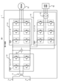
- the electronic device 1 shown in FIG. 1 is mounted on an AC feeding type railway vehicle, and converts the supplied AC power into AC power suitable for each of an electric motor 61 and an air conditioner 62, which are examples of loads, and converts The generated AC power is supplied to the electric motor 61 and the air conditioner 62 .
- the electric motor 61 is, for example, a three-phase induction motor that generates a propulsion force for a railway vehicle.
- the electronic device 1 supplies power to the electric motor 61 to generate propulsion of the railroad vehicle.
- the air-conditioning equipment 62 is an air-conditioning equipment in the railway vehicle. During operation of the railroad vehicle, specifically, when the railroad vehicle is running or stopped, the electronic device 1 supplies power to the air conditioner 62 to operate the air conditioner 62, and the air conditioner 62 is operated. The temperature is adjusted to the desired temperature.
- the electronic device 1 includes a positive terminal 1a connected to a power supply and a negative terminal 1b grounded.
- the electronic device 1 further includes a transformer 11 for stepping down the AC power supplied from the power supply connected to the positive terminal 1a, a converter 12 for converting the AC power stepped down by the transformer 11 into DC power, and the converter 12. It includes a capacitor C1 that is charged with the output DC power, and inverters 13 and 14 that convert the DC power input via the capacitor C1 into AC power.
- the positive terminal 1a is electrically connected, for example, to a current collector that acquires AC power supplied from a substation via a power supply line.
- the current collector corresponds to a power source that supplies power to the electronic device 1 .
- the power supply line is, for example, an overhead line or a third rail.
- Current collectors are pantographs or current collecting shoes.
- the negative terminal 1b is grounded by being short-circuited to the rail via a grounding brush, an earthing ring, a wheel, etc. (not shown).
- the transformer 11 has a primary winding with one end connected to the positive terminal 1 a and the other end connected to the negative terminal 1 b, and a secondary winding connected to the converter 12 .
- the transformer 11 steps down the 25 kV single-phase AC power supplied from the current collector to 1520 V single-phase AC power, and supplies the stepped-down AC power to the converter 12 .
- the converter 12 has two sets of two switching elements SW1 connected in series. One set of switching elements SW1 is connected in parallel to the other set of switching elements SW1. One end of the secondary winding of the transformer 11 is connected to the connection point of the two switching elements SW1 of one set, and the secondary winding of the transformer 11 is connected to the connection point of the two switching elements SW1 of the other set. ends are connected.
- Each switching element SW1 has an IGBT (Insulated Gate Bipolar Transistor) and a free wheel diode whose anode is connected to the emitter terminal of the IGBT and whose cathode is connected to the collector terminal of the IGBT.
- a gate signal from a control unit (not shown) is supplied to the gate terminal of the IGBT of each switching element SW1 provided in the converter 12 to control on/off of the IGBT, that is, on/off of each switching element SW1.
- the converter 12 converts AC power supplied from the transformer 11 into DC power.
- the capacitor C1 is charged with the DC power output by the converter 12.
- One end of the capacitor C1 is connected to a connection point between the positive terminal of the converter 12 and the positive terminals of the inverters 13 and 14 on the primary side.
- the other end of capacitor C1 is connected to a connection point between the negative terminal of converter 12 and the primary side negative terminals of inverters 13 and 14 .
- the inverter 13 has three sets of two switching elements SW2 connected in series.
- the three sets of switching elements SW2 respectively correspond to the U-phase, V-phase and W-phase of the three-phase AC power.
- a switching element SW2 corresponding to the U phase, a switching element SW2 corresponding to the V phase, and a switching element SW2 corresponding to the W phase are connected in parallel between the primary side positive terminal and the primary side negative terminal of the inverter 13. be.
- a connection point of the two switching elements SW2 corresponding to the U phase, a connection point of the two switching elements SW2 corresponding to the V phase, and a connection point of the two switching elements SW2 corresponding to the W phase are each connected to the electric motor 61. be.
- Each switching element SW2 has an IGBT and a freewheeling diode, like the switching element SW1.
- a gate signal from a control unit (not shown) is supplied to the gate terminals of the IGBTs of the switching elements SW2 of the inverter 13 to control on/off of the IGBTs, that is, on/off of the switching elements SW2.
- the switching operation of each switching element SW2 causes the inverter 13 to convert the DC power into three-phase AC power and supply the three-phase AC power to the electric motor 61 .
- the inverter 14 has three sets of two switching elements SW3 connected in series.
- the three sets of switching elements SW3 respectively correspond to the U-phase, V-phase and W-phase of the three-phase AC power.
- the switching element SW3 corresponding to the U phase, the switching element SW3 corresponding to the V phase, and the switching element SW3 corresponding to the W phase are connected in parallel between the primary side positive terminal and the primary side negative terminal of the inverter 14. be.
- Each switching element SW3 has an IGBT and a free wheel diode, like the switching element SW1.
- a gate signal from a control unit (not shown) is supplied to the gate terminal of the IGBT of each switching element SW3 of the inverter 14 to control the on/off of the IGBT, that is, the on/off of each switching element SW3.
- the switching operation of each switching element SW3 causes the inverter 14 to convert the DC power into three-phase AC power.
- the inverter 14 further has a transformer 15 that steps down the voltage of the three-phase AC power converted from the DC power to a voltage suitable for the air conditioner 62 .
- a connection point of the two switching elements SW3 corresponding to the U phase, a connection point of the two switching elements SW3 corresponding to the V phase, and a connection point of the two switching elements SW3 corresponding to the W phase are each connected to the transformer 15. be done.
- the three-phase AC power stepped down by the transformer 15 is supplied to the air conditioner 62 .
- the switching elements SW1, SW2 and SW3 are repeatedly turned on and off, that is, perform switching operations and generate heat.
- the air conditioner 62 must be operated while the railway vehicle is stopped. Therefore, while the railway vehicle is stopped, inverter 13 is stopped and converter 12 and inverter 14 are in operation.
- the switching element SW2 does not generate heat, but the switching elements SW1 and SW3 repeatedly turn on and off and generate heat.
- the electronic device 1 cools the electronic components including the switching elements SW1, SW2, and SW3 by running wind when the railroad vehicle is running, and cools the electronic components including the switching elements SW1 and SW3 by natural convection when the railroad vehicle is stopped.
- the electronic device 1 is provided on the roof 100a of the vehicle 100.
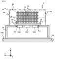
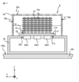
- FIG. 3 which is a cross-sectional view taken along line III-III in FIG.
- a heat transfer member 22 is attached to the second main surface 21b and transfers heat transferred from the electronic component via the heat receiving block 21 in a direction away from the second main surface 21b.
- the electronic device 1 further includes one or more fins 23 attached to the heat transfer member 22 and dissipating the heat transferred from the electronic component via the heat receiving block 21 and the heat transfer member 22 to the surrounding air. .
- the electronic device 1 preferably further includes a housing 20 that is installed on the roof 100a and houses electronic components including the switching elements SW1, SW2, and SW3.
- the heat receiving block 21 may be attached to the housing 20 while closing the opening 20a of the housing 20 .
- the electronic device 1 preferably includes a cover 30 that covers the heat transfer member 22 and the fins 23 and is attached to the housing 20 .
- the Z axis indicates the vertical direction with the vehicle 100 positioned horizontally.
- the X-axis indicates the traveling direction of the vehicle 100 .
- the Y-axis indicates the width direction of vehicle 100 .
- the X-, Y-, and Z-axes are orthogonal to each other. The same applies to subsequent figures.
- the housing 20 is attached to the upper part of the roof 100a in the vertical direction.
- the housing 20 has such rigidity and strength that it does not deform even under the maximum expected vibration of the railway vehicle.
- the housing 20 is made of a metal member such as iron or aluminum.
- An opening 20a is formed in the upper portion of the housing 20 in the vertical direction.
- the heat receiving block 21 is attached to the housing 20 while closing the opening 20a.
- the heat receiving block 21 is a flat plate member made of a member having high thermal conductivity, such as a metal member such as iron or aluminum, and attached to the outer surface of the housing 20 while closing the opening 20a.
- Electronic components that generate heat, specifically, switching elements SW1, SW2, and SW3 are attached to the first main surface 21a of the heat receiving block 21 .
- a heat transfer member 22 is attached to a second main surface 21b located opposite to the first main surface 21a. With the vehicle 100 positioned horizontally, the first main surface 21a and the second main surface 21b are horizontal.
- the heat transfer member 22 extends in a direction away from the second main surface 21b, and transfers heat transferred from the electronic component via the heat receiving block 21 in a direction away from the second main surface 21b.
- the heat transfer member 22 has a heat pipe with a refrigerant sealed inside.
- the heat transfer member 22 has, as a heat pipe, a mother pipe 24 attached to the heat receiving block 21 and a branch pipe 25 attached to the mother pipe 24 and communicating with the mother pipe 24 .
- the main pipe 24 and the branch pipe 25 are filled with a refrigerant that exists in a gas-liquid two-phase state at room temperature.
- the coolant is, for example, water.
- the main pipe 24 and the branch pipes 25 are arranged symmetrically with respect to the XZ plane.
- FIG. 3 and FIG. 4 which is a cross-sectional view taken along line IV-IV in FIG. 3, a plurality of mother pipes 24 extending in the X-axis direction are arranged side by side in the Y-axis direction.
- twenty mother pipes 24 extending in the X-axis direction are arranged side by side in the Y-axis direction.
- the mother pipe 24 is inserted into a groove formed in the second main surface 21b of the heat receiving block 21 and attached to the heat receiving block 21 by an attachment method such as bonding with an adhesive, brazing, or soldering.
- the main pipe 24 is a pipe made of a member having a high thermal conductivity, such as a metal member such as iron or aluminum.
- a plurality of branch pipes 25 are attached to each mother pipe 24 .
- Each branch pipe 25 extends in a direction away from the heat receiving block 21, for example, in the Z-axis positive direction.
- the branch pipe 25 is attached to the mother pipe 24 by an attachment method such as welding, brazing, or soldering, and communicates with the mother pipe 24 .
- an attachment method such as welding, brazing, or soldering
- eight branch pipes 25 arranged in the X-axis direction are attached to one mother pipe 24 .
- illustration of the cover 30 is omitted.
- the branch pipe 25 is a pipe made of a member having high thermal conductivity, such as a metal member such as iron or aluminum.
- the length of the branch pipe 25 in the Z-axis direction is set within the vehicle limit on the cross section orthogonal to the traveling direction of the vehicle 100, that is, the YZ plane. Vehicle limits indicate the maximum dimensions of vehicle 100 .
- the length in the Z-axis direction of the branch pipes 25 attached to the mother pipes 24 located at each of the two ends in the Y-axis direction is set at the center in the Y-axis direction. It is shorter than the length in the Z-axis direction of the branch pipes 25 attached to the eight mother pipes 24 located.
- Four mother pipes 24 are provided between the eight mother pipes 24 positioned in the center in the Y-axis direction and the two mother pipes 24 positioned at the ends in the Y-axis direction.
- the length in the Z-axis direction of the branch pipes 25 attached to the four mother pipes 24 is shorter than the length in the Z-axis direction of the branch pipes 25 attached to the eight mother pipes 24 described above. longer than the length in the Z-axis direction of the branch pipe 25 attached to the .
- the fins 23 are attached to the heat transfer member 22 . Specifically, the fins 23 are attached to the heat transfer member 22 in a state in which the heat transfer member 22 is inserted through the through holes formed in the fins 23 .
- the fins 23 attached to the heat transfer member 22 radiate the heat transferred from the electronic component through the heat receiving block 21 and the heat transfer member 22 to the surrounding air.
- the fin 23 is a plate member made of a member having high thermal conductivity, such as a metal member such as iron or aluminum.
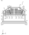
- At least one of the fins 23 is formed with at least one ventilation hole 23a that guides air in a direction away from the second main surface 21b, for example, in the Z-axis positive direction.
- the ratio of the opening area of the ventilation holes 23a in the first region including the center of the fin 23 in the X-axis direction or the Y-axis direction is the same as that in the second region having the same area as the first region located on either side of the first region. It is higher than the ratio occupied by the opening area of 23a.
- the ratio of the opening area of the ventilation holes 23a in the first region including the center in the X-axis direction or the Y-axis direction on the main surface of the fin 23 is the first area located across the first region on the main surface. It is higher than the ratio occupied by the opening area of the ventilation holes 23a in the second area having the same area as the area.
- a plurality of circular fins 23 are arranged linearly in the Y-axis direction in a first region R1 including the center of each fin 23 in the X-axis direction, which is a region surrounded by a dashed line. Ventilation holes 23a are formed. In each fin 23, the ventilation hole 23a is not formed in the second region R2, which is the region surrounded by the chain double-dashed lines located on both sides of the first region R1. The second region R2 is located across the first region R1 in the X-axis direction.
- the ventilation holes 23a are formed in the first region R1, the ventilation holes 23a are not formed in the second region R2. is higher than the ratio occupied by the opening area of the ventilation holes 23a in the second region R2.
- the main surface of the fins 23 is preferably parallel to the X-axis. Since the traveling wind generated when the vehicle 100 travels flows in the X-axis direction, the heat can be efficiently transferred from the fins 23 to the traveling wind flowing between the fins 23 by making the main surfaces of the fins 23 parallel to the X-axis. can be done.
- the fins 23 are formed with the ventilation holes 23a as described above.
- the air warmed by heat transfer from the fins 23 moves in the positive direction of the Z-axis through the ventilation holes 23a. Due to the air flow described above, air flows from the outside of the cover 30 into the inside of the cover 30 , and heat is transferred from the fins 23 to the inflowing air.
- the ventilation holes 23a are formed in the first region R1 of the fins 23 in the X-axis direction instead of being formed over the entire surface of the fins 23. As shown in FIG.
- a plurality of fins 23 are arranged side by side in the Y-axis direction and the Z-axis direction. As shown in FIG. 3, six fins 23 are arranged in the Y-axis direction. Four fins 23 are arranged in the Z-axis direction at both ends in the Y-axis direction. Five fins 23 are arranged in the Z-axis direction at positions adjacent to the fins 23 located at both ends in the Y-axis direction. Seven fins 23 are arranged in the Z-axis direction at the center in the Y-axis direction. Each of the fins 23 is attached to the heat transfer member 22, that is, the branch pipe 25, with its main surface horizontal when the vehicle 100 is positioned horizontally.
- the cover 30 is attached to the housing 20 while covering the heat receiving block 21 , the heat transfer member 22 and the fins 23 .
- the surface of the cover 30 along the X-axis direction is provided with a plurality of ventilators for allowing external air to flow into the cover 30 and for causing the air that has flowed near the heat transfer member 22 and the fins 23 to flow out of the cover 30.
- a hole 30a is formed.
- the surface of the cover 30 that intersects the X-axis direction allows external air to flow into the inside of the cover 30, and the air that has flowed near the heat transfer member 22 and the fins 23 is directed to the outside of the cover 30.
- a plurality of ventilation holes 30b are formed to allow the air to flow out.
- the cooling of the electronic components included in the electronic device 1 having the above configuration will be described below.
- Heat generated by at least one of switching elements SW1, SW2, and SW3 is transferred to the refrigerant through heat receiving block 21 and main pipe 24.
- the refrigerant vaporizes.
- the vaporized refrigerant flows from the main pipe 24 into the branch pipe 25 and moves inside the branch pipe 25 in the positive Z-axis direction.
- the refrigerant is cooled and liquefied by transferring heat to the air around the heat transfer member 22 via the branch pipes 25 and the fins 23 .
- the liquefied refrigerant moves along the inner wall of the branch pipe 25 in the negative direction of the Z axis.
- the heat generated by at least one of the switching elements SW1, SW2, and SW3 is transferred to the air around the heat transfer member 22, and the switching heat is generated.
- the elements SW1, SW2, SW3 are cooled.
- traveling wind is generated that flows in the negative direction of the X axis as indicated by an arrow AR1 in FIG.
- Running wind passes between the fins 23 . As the running wind passes through the fins 23, heat is transferred from the fins 23 to the running wind to cool the switching elements SW1, SW2, and SW3.
- the running wind shown in FIG. 6 is not generated while the vehicle 100 is stopped. Since the fins 23 included in the electronic device 1 are formed with ventilation holes 23a, the air heated by heat transfer from the fins 23 or the branch pipes 25 flows through the ventilation holes 23a as indicated by the arrow AR2 in FIG. Move in the positive direction of the Z-axis. In FIG. 7, only part of the air flow is shown to avoid complicating the drawing. The air that has moved in the positive direction of the Z-axis flows out of the cover 30 through the ventilation holes 30a formed in the vertical upper portion of the cover 30 .
- the air that has flowed into the cover 30 through the ventilation holes 30b formed in the surface of the cover 30 on the negative side of the X-axis flows between the fins 23 in the positive direction of the X-axis. 23 reaches the first region R1 in the X-axis direction.
- the air that has flowed into the cover 30 flows between the fins 23 as described above, is warmed by heat transferred from the fins 23, and reaches the first region R1 of the fins 23 in the X-axis direction.
- the warmed air moves in the Z-axis positive direction through the ventilation holes 23a of the fins 23 and flows out of the cover 30 through the ventilation holes 30a. Since the ventilation holes 23a are formed in the fins 23, air flows in the positive direction of the Z-axis. In this manner, by utilizing natural convection, switching elements SW1, SW2, and SW3 can be cooled even when vehicle 100 is stopped.
- the total area of the openings of the ventilation holes 23a in each fin 23 is increased, the heat radiation area is reduced and the cooling performance is degraded. It is preferably determined according to the required cooling performance. Specifically, the number of ventilation holes 23a and the shape of each ventilation hole 23a are preferably determined according to the cooling performance required when the vehicle is running and when the vehicle is stopped.
- the electronic device 1 includes the fins 23 in which the ventilation holes 23a are formed.
- the air warmed by heat transfer from the fins 23 inside the cover 30 moves in the positive direction of the Z-axis through the ventilation holes 23a.
- the air inside the cover 30 moves in the Z-axis positive direction through the ventilation holes 23 a and flows out of the cover 30 through the ventilation holes 30 a of the cover 30 , the air outside the cover 30 moves inside the cover 30 .
- influx As described above, since air flows even when vehicle 100 is stopped, electronic device 1 can cool electronic components including switching elements SW1, SW2, and SW3 using natural convection.
- the present disclosure is not limited to the above embodiments.
- only some of the fins 23 may have the ventilation holes 23a.
- the configuration of the electronic device 2 is shown in FIG. 9 and FIG. 10, which is a cross-sectional view taken along line XX in FIG.
- the electronic device 2 includes fins 23 arranged in the same manner as the electronic device 1 .
- no ventilation holes 23a are formed in the four fins 23 located in the center in the Y-axis direction and on the positive side of the Z-axis.
- the air warmed by heat transfer from the fins 23 moves in the positive direction of the Z axis through the ventilation holes 23a.
- the air warmed by heat transfer from the fins 23 moves through the ventilation holes 23a in the positive direction of the Z-axis as indicated by the arrow AR5, forming the ventilation holes 23a. It reaches the fin 23 which is not covered.
- the air that has reached the fins 23 without the ventilation holes 23a moves in the positive Z-axis direction, bypassing the fins 23 without the ventilation holes 23a, as indicated by an arrow AR6.
- FIG. 12 shows the configuration of the electronic device 3 as another example.
- the fin 23 located at the center in the Y-axis direction has a ventilation hole 23a, and the fins 23 located at both ends in the Y-axis direction do not have a ventilation hole 23a.
- the fins 23 positioned at both ends in the Y-axis direction are arranged so that one of the ends in the Y-axis direction near the center of the vehicle 100 extends vertically when the vehicle 100 is positioned horizontally. is attached to the heat transfer member 22, specifically to the branch pipe 25, in such a direction that the position of is higher than the vertical position of the other end.
- the air warmed by heat transfer from the fins 23 moves in the positive direction of the Z axis through the ventilation holes 23a.
- the air warmed by heat transfer from the fins 23 moves along the fins 23 toward the center of the vehicle 100, and then travels between the fins 23 along the Z-axis. Move in the positive direction.
- the shape and size of the ventilation holes 23a formed in each fin 23 are the same, but the shape and size of the ventilation holes 23a are not limited to the above example. Furthermore, the number of ventilation holes 23a is not limited to the above example. Specifically, in each fin 23, the ratio of the opening area of the ventilation holes 23a in the first region R1 in the X-axis direction or the Y-axis direction of the fin 23 is the same as that in the second region R2 located across the first region R1.
- the shape, size, and number of the ventilation holes 23a are arbitrary as long as they are higher than the ratio of the opening area of the holes 23a.
- the shape of the ventilation hole 23a is not limited to a circle, and may be oval or square.
- the shape of each ventilation hole 23a may be different from each other.
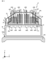
- FIG. 14 shows the configuration of the electronic device 4 as another example.
- the ventilation holes 23a formed in the fins 23 have the same shape. More ventilation holes 23a are formed than in the second region R2, which is the region surrounded by the dashed-dotted lines sandwiched in the axial direction.
- the illustration of the cover 30 and the heat transfer member 22 is omitted in order to avoid complication of the drawing. Since more ventilation holes 23a are formed in the first region R1 than in the second region R2, most of the air that has flowed in from the outside of the cover 30 moves from the second region R2 to the first region R1, It flows in the Z-axis positive direction through the ventilation hole 23a formed in R1.
- FIG. 15 shows the configuration of an electronic device 5 as another example.
- the ventilation holes 23a larger than the second region R2 are formed in the first region R1.
- the illustration of the cover 30 and the heat transfer member 22 is omitted in order to avoid complication of the drawing. Since the first region R1 has a larger ventilation hole 23a, most of the air that has flowed in from the outside of the cover 30 moves from the second region R2 to the first region R1 and is formed in the first region R1. It flows in the Z-axis positive direction through the ventilation holes 23a.
- the positions and shapes of the ventilation holes 23a in the fins 23 arranged in the Z-axis direction are the same, but the positions and shapes of the ventilation holes 23a in the fins 23 arranged in the Z-axis direction are different from each other.
- the configuration of the electronic device 6 is shown in FIG. 16 and FIG. 17, which is a cross-sectional view taken along line XVII-XVII in FIG.
- the total opening area of the ventilation holes 23a formed in the fins 23 adjacent to the heat receiving block 21 is equal to the total opening area of the ventilation holes 23a formed in the fins 23 provided farther from the heat receiving block 21 than the fins 23. It is smaller than the total opening area of the holes 23a.
- the diameter of the ventilation holes 23a formed in the fins 23 adjacent to the heat receiving block 21 is the diameter of the ventilation holes 23a formed in the fins 23 provided farther from the heat receiving block 21 than the fins 23. less than Furthermore, in the central portion in the Y-axis direction, one ventilation hole 23a is formed in the fin 23 adjacent to the heat receiving block 21, whereas the ventilation hole 23a is provided at a position farther from the heat receiving block 21 than the fin 23.
- the fin 23 is formed with three ventilation holes 23a.
- ventilation holes 23a are formed in a first region R1 including the center in the X-axis direction, and are aligned in a straight line in the Y-axis direction. It is not limited to the above examples. An example of a case in which it is easier to take air into the cover 30 in the Y-axis direction than in the X-axis direction because another on-vehicle device is adjacent in the X-axis direction.
- FIG. 18 shows the configuration of the electronic device 7 which is .
- a plurality of circular ventilation holes are arranged linearly in the X-axis direction in a first region R1 including the center of each fin 23 in the Y-axis direction, which is a region surrounded by a dashed line. 23a is formed.
- the ventilation hole 23a is not formed in the second region R2, which is the region surrounded by the two-dot chain line and located on both sides of the first region R1.
- the first region R1 and the second region R2 are shown in some of the fins 23 in FIG.
- the second region R2 is located across the first region R1 in the Y-axis direction.
- the ventilation holes 23a are formed in the first region R1, whereas the ventilation holes 23a are not formed in the second region R2. 23 is higher than the ratio occupied by the opening area of the ventilation holes 23a in the second region R2.
- Positioning across the first region R1 includes positioning around the first region R1.
- the second region R2 may surround the outer periphery of the first region R1.
- the mounting position of the electronic device 1-7 is not limited to the above example.
- FIG. 19 and FIG. 20 which is a cross-sectional view taken along line XX-XX in FIG. good.
- the accommodation portion 100b is a recess formed in the roof 100a of the vehicle 100 and having an open top in the vertical direction.
- the opening surface of the housing portion 100b is positioned on the same plane as the upper end of the roof 100a of the vehicle 100 in the vertical direction.
- the housing portion 100 b houses the housing 20 of the electronic device 1 .
- the bottom surface of the housing 20 is attached to the bottom surface of the housing portion 100b.
- At least part of the heat transfer member 22 and at least part of the fins 23 are preferably positioned vertically above the upper end of the roof 100a in the vertical direction.
- the inverter 14 can supply power not only to the air conditioner 62 but also to any load device that is in operation when the vehicle 100 is stopped.
- the inverter 14 can supply power to a lighting device, a door opening/closing device of the vehicle 100, and the like.
- the shape of the housing 20 is arbitrary as long as it accommodates electronic components including the switching elements SW1, SW2, and SW3 inside and can be attached to the roof 100a.
- the shape of the heat-receiving block 21 is not limited to the above-described example, and may be any shape as long as it closes the opening 20a of the housing 20 and allows electronic components including the switching elements SW1, SW2, and SW3 and the heat transfer member 22 to be attached.
- the heat-receiving block 21 may be formed of a plate-like member having a non-uniform thickness.
- the heat-receiving block 21 may be formed of a single plate-like member, or may be formed by combining a plurality of plate-like members.
- the electronic parts attached to the heat receiving block 21 are not limited to the switching elements SW1, SW2, and SW3, and may be arbitrary electronic parts housed inside the housing 20, such as thyristors and diodes.
- the heat transfer member 22 is not limited to a heat pipe, and may be any member as long as it transfers heat in a direction away from the second main surface 21b.
- the heat transfer member 22 may be a rod-shaped member made of a member having high thermal conductivity, such as a metal member such as iron or aluminum.
- the arrangement of the heat transfer members 22, specifically, the arrangement of the branch pipes 25 is not limited to the above example, and is arbitrary as long as it is possible to cool the electronic components using natural convection.
- the shape of the heat transfer member 22, specifically, the shape of the main pipe 24 and the branch pipe 25 is not limited to the above example, and any shape can be used as long as it can transfer heat in a direction away from the second main surface 21b. is.
- the main pipe 24 and the branch pipe 25 may be integrally formed to form the heat transfer member 22, which is a U-shaped or L-shaped heat pipe.
- the shape of the cross section perpendicular to the extending direction of the main pipe 24 and the branch pipes 25 is not limited to a circular shape, and may be a flat shape.
- a flattened shape is a shape obtained by deforming a part of a circle to have a narrower width than the original circle, and includes an ellipse, a streamlined shape, an ellipse, and the like.
- An ellipse means an outer shape obtained by connecting the outer edges of two circles having the same diameter with two straight lines.
- Each fin 23 may be made of the same material, or at least one of the fins 23 may be made of a material different from the other fins 23 .
- the thermal conductivity of at least one of the fins 23 is different from that of the other fins 23 .
- the thermal conductivity of the fins 23 located vertically upward is preferably higher than the thermal conductivity of the fins 23 located vertically downward.
- the vertically upper fins 23 may be made of copper and the vertically lower fins 23 may be made of aluminum.
- the number, shape, and arrangement position of the fins 23 are not limited to the above examples, and the fins 23 may be provided with ventilation holes 23a for guiding air in the positive direction of the Z-axis in the central portion of the fins 23 in the X-axis direction or the Y-axis direction.
- the fin 23 may be a plate-like member having a curved surface, or may be a plate-like member having a non-uniform thickness.
- the fins 23 may be flat plate members attached to the heat transfer members 22 such that the main surfaces thereof are inclined with respect to the horizontal plane when the vehicle 100 is horizontally positioned.
- each fin 23 may have a different shape.
- a plurality of fins 23 having different widths in the Y-axis direction may be arranged in the Z-axis direction.
- the shape of the cover 30 is arbitrary as long as it covers the heat transfer member 22 and the fins 23 and allows air to flow inside.
- the cover 30 may have a curved top surface in the vertical direction.
- the cover 30 may have a flat top surface in the vertical direction.
- the cover 30 preferably has a shape that maximizes internal space within the vehicle limits.
- the electronic device 1-7 is not limited to an AC feeding type railway vehicle, and may be mounted on a DC feeding type railway vehicle.
- the vehicle on which the electronic device 1-7 is mounted is not limited to a railroad vehicle, and may be any moving object such as a trolleybus or a streetcar that generates running wind.
Landscapes
- Engineering & Computer Science (AREA)
- Life Sciences & Earth Sciences (AREA)
- Sustainable Development (AREA)
- Sustainable Energy (AREA)
- Power Engineering (AREA)
- Transportation (AREA)
- Mechanical Engineering (AREA)
- Cooling Or The Like Of Electrical Apparatus (AREA)
Abstract
Un dispositif électronique (1) est pourvu d'un bloc de réception de chaleur (21), d'éléments de transfert de chaleur (22) et d'ailettes (23). Au moins une des ailettes (23) comporte un ou plusieurs trous de ventilation (23a) par lesquels de l'air est guidé dans une direction à l'écart d'une seconde surface principale (21b) du bloc de réception de chaleur (21). Dans les ailettes (23) comportant les trous de ventilation (23a) formés à l'intérieur de celle-ci, la proportion de la zone d'ouverture des trous de ventilation (23a) dans une première région qui comprend le centre d'un véhicule dans la direction de déplacement ou la direction de la largeur est supérieure à la proportion de la zone d'ouverture des trous de ventilation (23a) dans des secondes régions qui sont situées de façon à prendre en sandwich la première région et ont la même surface que la première région.
Priority Applications (2)
| Application Number | Priority Date | Filing Date | Title |
|---|---|---|---|
| PCT/JP2021/039975 WO2023073909A1 (fr) | 2021-10-29 | 2021-10-29 | Dispositif électronique |
| JP2023556016A JP7408031B2 (ja) | 2021-10-29 | 2021-10-29 | 電子機器 |
Applications Claiming Priority (1)
| Application Number | Priority Date | Filing Date | Title |
|---|---|---|---|
| PCT/JP2021/039975 WO2023073909A1 (fr) | 2021-10-29 | 2021-10-29 | Dispositif électronique |
Publications (1)
| Publication Number | Publication Date |
|---|---|
| WO2023073909A1 true WO2023073909A1 (fr) | 2023-05-04 |
Family
ID=86157604
Family Applications (1)
| Application Number | Title | Priority Date | Filing Date |
|---|---|---|---|
| PCT/JP2021/039975 WO2023073909A1 (fr) | 2021-10-29 | 2021-10-29 | Dispositif électronique |
Country Status (2)
| Country | Link |
|---|---|
| JP (1) | JP7408031B2 (fr) |
| WO (1) | WO2023073909A1 (fr) |
Citations (5)
| Publication number | Priority date | Publication date | Assignee | Title |
|---|---|---|---|---|
| JPH0722551A (ja) * | 1993-07-02 | 1995-01-24 | Furukawa Electric Co Ltd:The | ヒートパイプ式半導体冷却器 |
| JPH1154680A (ja) * | 1997-07-30 | 1999-02-26 | Hitachi Ltd | 放熱構造とこれを用いた電子装置 |
| JP2009124038A (ja) | 2007-11-16 | 2009-06-04 | Toyo Electric Mfg Co Ltd | 屋根置型電気車制御装置用半導体冷却装置 |
| JP2012054316A (ja) * | 2010-08-31 | 2012-03-15 | Hitachi Ltd | 車載用電力変換装置の冷却装置および鉄道車両用電力変換装置 |
| JP2019029551A (ja) * | 2017-08-01 | 2019-02-21 | 富士電機株式会社 | 鉄道車両用電力変換装置 |
-
2021
- 2021-10-29 JP JP2023556016A patent/JP7408031B2/ja active Active
- 2021-10-29 WO PCT/JP2021/039975 patent/WO2023073909A1/fr active Application Filing
Patent Citations (5)
| Publication number | Priority date | Publication date | Assignee | Title |
|---|---|---|---|---|
| JPH0722551A (ja) * | 1993-07-02 | 1995-01-24 | Furukawa Electric Co Ltd:The | ヒートパイプ式半導体冷却器 |
| JPH1154680A (ja) * | 1997-07-30 | 1999-02-26 | Hitachi Ltd | 放熱構造とこれを用いた電子装置 |
| JP2009124038A (ja) | 2007-11-16 | 2009-06-04 | Toyo Electric Mfg Co Ltd | 屋根置型電気車制御装置用半導体冷却装置 |
| JP2012054316A (ja) * | 2010-08-31 | 2012-03-15 | Hitachi Ltd | 車載用電力変換装置の冷却装置および鉄道車両用電力変換装置 |
| JP2019029551A (ja) * | 2017-08-01 | 2019-02-21 | 富士電機株式会社 | 鉄道車両用電力変換装置 |
Also Published As
| Publication number | Publication date |
|---|---|
| JP7408031B2 (ja) | 2024-01-04 |
| JPWO2023073909A1 (fr) | 2023-05-04 |
Similar Documents
| Publication | Publication Date | Title |
|---|---|---|
| CA2688583C (fr) | Dispositif de conversion de puissance | |
| JP3469475B2 (ja) | 鉄道車両用半導体冷却装置 | |
| WO2013015106A1 (fr) | Dispositif de conversion électrique | |
| JP5488540B2 (ja) | 半導体モジュール | |
| JP5407275B2 (ja) | 電力変換装置 | |
| CN103907278A (zh) | Dc-dc转换器装置和电力转换装置 | |
| US10021816B2 (en) | Power converter arrangement and method for producing a power converter arrangement | |
| JP5028822B2 (ja) | パワーモジュールの冷却装置 | |
| JP2012064609A (ja) | 半導体パワーモジュール及び電力変換装置 | |
| JP6055868B2 (ja) | 電力変換装置 | |
| JP6169187B2 (ja) | 電力変換装置 | |
| EP2034602A1 (fr) | Convertisseur de puissance | |
| EP0590502B1 (fr) | Onduleur pour matériel électrique | |
| WO2019021532A1 (fr) | Dispositif de conversion de puissance électrique | |
| WO2023073909A1 (fr) | Dispositif électronique | |
| US20210066991A1 (en) | Motor device | |
| TW201601423A (zh) | 電力變換裝置及車輛用控制裝置 | |
| WO2023144914A1 (fr) | Dispositif électronique | |
| US11818868B2 (en) | Cooling device and power conversion device | |
| JP2011019305A (ja) | 鉄道車両電動機駆動用インバータ装置 | |
| WO2022264301A1 (fr) | Dispositif électronique | |
| JP6081091B2 (ja) | 鉄道車両用制御装置 | |
| CN218788733U (zh) | 功率转换装置 | |
| JPH06163770A (ja) | 電気車用インバータ装置の冷却装置 | |
| WO2023199445A1 (fr) | Appareil électronique |
Legal Events
| Date | Code | Title | Description |
|---|---|---|---|
| 121 | Ep: the epo has been informed by wipo that ep was designated in this application |
Ref document number: 21962451 Country of ref document: EP Kind code of ref document: A1 |
|
| WWE | Wipo information: entry into national phase |
Ref document number: 2023556016 Country of ref document: JP |