WO2023073757A1 - ロータ、電動機、送風機および空気調和装置 - Google Patents
ロータ、電動機、送風機および空気調和装置 Download PDFInfo
- Publication number
- WO2023073757A1 WO2023073757A1 PCT/JP2021/039271 JP2021039271W WO2023073757A1 WO 2023073757 A1 WO2023073757 A1 WO 2023073757A1 JP 2021039271 W JP2021039271 W JP 2021039271W WO 2023073757 A1 WO2023073757 A1 WO 2023073757A1
- Authority
- WO
- WIPO (PCT)
- Prior art keywords
- rotor
- magnet
- pole
- magnetic
- permanent magnet
- Prior art date
- Legal status (The legal status is an assumption and is not a legal conclusion. Google has not performed a legal analysis and makes no representation as to the accuracy of the status listed.)
- Ceased
Links
Images


Classifications
-
- H—ELECTRICITY
- H02—GENERATION; CONVERSION OR DISTRIBUTION OF ELECTRIC POWER
- H02K—DYNAMO-ELECTRIC MACHINES
- H02K1/00—Details of the magnetic circuit
- H02K1/06—Details of the magnetic circuit characterised by the shape, form or construction
- H02K1/22—Rotating parts of the magnetic circuit
- H02K1/27—Rotor cores with permanent magnets
- H02K1/2706—Inner rotors
- H02K1/272—Inner rotors the magnetisation axis of the magnets being perpendicular to the rotor axis
- H02K1/274—Inner rotors the magnetisation axis of the magnets being perpendicular to the rotor axis the rotor consisting of two or more circumferentially positioned magnets
- H02K1/2746—Inner rotors the magnetisation axis of the magnets being perpendicular to the rotor axis the rotor consisting of two or more circumferentially positioned magnets the rotor consisting of magnets arranged with the same polarity, e.g. consequent pole type
-
- H—ELECTRICITY
- H02—GENERATION; CONVERSION OR DISTRIBUTION OF ELECTRIC POWER
- H02K—DYNAMO-ELECTRIC MACHINES
- H02K1/00—Details of the magnetic circuit
- H02K1/06—Details of the magnetic circuit characterised by the shape, form or construction
- H02K1/22—Rotating parts of the magnetic circuit
- H02K1/27—Rotor cores with permanent magnets
- H02K1/2706—Inner rotors
- H02K1/272—Inner rotors the magnetisation axis of the magnets being perpendicular to the rotor axis
- H02K1/274—Inner rotors the magnetisation axis of the magnets being perpendicular to the rotor axis the rotor consisting of two or more circumferentially positioned magnets
- H02K1/2753—Inner rotors the magnetisation axis of the magnets being perpendicular to the rotor axis the rotor consisting of two or more circumferentially positioned magnets the rotor consisting of magnets or groups of magnets arranged with alternating polarity
- H02K1/276—Magnets embedded in the magnetic core, e.g. interior permanent magnets [IPM]
-
- H—ELECTRICITY
- H02—GENERATION; CONVERSION OR DISTRIBUTION OF ELECTRIC POWER
- H02K—DYNAMO-ELECTRIC MACHINES
- H02K1/00—Details of the magnetic circuit
- H02K1/06—Details of the magnetic circuit characterised by the shape, form or construction
- H02K1/22—Rotating parts of the magnetic circuit
- H02K1/27—Rotor cores with permanent magnets
- H02K1/2706—Inner rotors
- H02K1/272—Inner rotors the magnetisation axis of the magnets being perpendicular to the rotor axis
- H02K1/274—Inner rotors the magnetisation axis of the magnets being perpendicular to the rotor axis the rotor consisting of two or more circumferentially positioned magnets
- H02K1/2753—Inner rotors the magnetisation axis of the magnets being perpendicular to the rotor axis the rotor consisting of two or more circumferentially positioned magnets the rotor consisting of magnets or groups of magnets arranged with alternating polarity
- H02K1/276—Magnets embedded in the magnetic core, e.g. interior permanent magnets [IPM]
- H02K1/2766—Magnets embedded in the magnetic core, e.g. interior permanent magnets [IPM] having a flux concentration effect
-
- H—ELECTRICITY
- H02—GENERATION; CONVERSION OR DISTRIBUTION OF ELECTRIC POWER
- H02K—DYNAMO-ELECTRIC MACHINES
- H02K29/00—Motors or generators having non-mechanical commutating devices, e.g. discharge tubes or semiconductor devices
- H02K29/03—Motors or generators having non-mechanical commutating devices, e.g. discharge tubes or semiconductor devices with a magnetic circuit specially adapted for avoiding torque ripples or self-starting problems
-
- H—ELECTRICITY
- H02—GENERATION; CONVERSION OR DISTRIBUTION OF ELECTRIC POWER
- H02K—DYNAMO-ELECTRIC MACHINES
- H02K7/00—Arrangements for handling mechanical energy structurally associated with dynamo-electric machines, e.g. structural association with mechanical driving motors or auxiliary dynamo-electric machines
- H02K7/14—Structural association with mechanical loads, e.g. with hand-held machine tools or fans
-
- H—ELECTRICITY
- H02—GENERATION; CONVERSION OR DISTRIBUTION OF ELECTRIC POWER
- H02K—DYNAMO-ELECTRIC MACHINES
- H02K1/00—Details of the magnetic circuit
- H02K1/06—Details of the magnetic circuit characterised by the shape, form or construction
- H02K1/22—Rotating parts of the magnetic circuit
- H02K1/223—Rotor cores with windings and permanent magnets
-
- H—ELECTRICITY
- H02—GENERATION; CONVERSION OR DISTRIBUTION OF ELECTRIC POWER
- H02K—DYNAMO-ELECTRIC MACHINES
- H02K1/00—Details of the magnetic circuit
- H02K1/06—Details of the magnetic circuit characterised by the shape, form or construction
- H02K1/22—Rotating parts of the magnetic circuit
- H02K1/27—Rotor cores with permanent magnets
- H02K1/2706—Inner rotors
- H02K1/272—Inner rotors the magnetisation axis of the magnets being perpendicular to the rotor axis
- H02K1/274—Inner rotors the magnetisation axis of the magnets being perpendicular to the rotor axis the rotor consisting of two or more circumferentially positioned magnets
-
- H—ELECTRICITY
- H02—GENERATION; CONVERSION OR DISTRIBUTION OF ELECTRIC POWER
- H02K—DYNAMO-ELECTRIC MACHINES
- H02K15/00—Processes or apparatus specially adapted for manufacturing, assembling, maintaining or repairing of dynamo-electric machines
- H02K15/02—Processes or apparatus specially adapted for manufacturing, assembling, maintaining or repairing of dynamo-electric machines of stator or rotor bodies
- H02K15/021—Magnetic cores
- H02K15/022—Magnetic cores with salient poles
- H02K15/0225—Magnetic cores with salient poles with claw-shaped poles
-
- H—ELECTRICITY
- H02—GENERATION; CONVERSION OR DISTRIBUTION OF ELECTRIC POWER
- H02K—DYNAMO-ELECTRIC MACHINES
- H02K2213/00—Specific aspects, not otherwise provided for and not covered by codes H02K2201/00 - H02K2211/00
- H02K2213/03—Machines characterised by numerical values, ranges, mathematical expressions or similar information
Definitions
- the present disclosure relates to rotors, electric motors, blowers, and air conditioners.
- the present disclosure has been made to solve the above problems, and aims to increase the magnetic force of a permanent magnet while suppressing an increase in manufacturing costs.
- the rotor of the present disclosure has N/2 (N is an even number) magnet magnetic poles and N/2 virtual magnetic poles.
- the rotor has an annular rotor core centered on the axis and a plurality of permanent magnets attached to the rotor core. All N/2 magnet magnetic poles are formed by at least one permanent magnet of the plurality of permanent magnets, and all N/2 virtual magnetic poles are formed by a portion of the rotor core.
- the pole centerline of each magnet pole is defined by a straight line passing through the center of the magnet pole and the axis in the circumferential direction of the rotor core.
- At least one permanent magnet forming the magnet poles has a first corner facing the outer periphery of the rotor core and furthest from the pole center line on one side of the pole center line, and a first corner facing the outer periphery and at the pole center line. and a second corner furthest from the polar centerline on the other side.
- An angle ⁇ m between a straight line passing through the first corner and the axis and a straight line passing through the second corner and the axis satisfies ⁇ m ⁇ 360/N [degrees].
- the angle ⁇ m is 360/N [degree] or more, the area of the magnetic pole face of the permanent magnet per unit length in the axial direction can be increased. As a result, it is possible to increase the magnetic force of the permanent magnet while suppressing an increase in manufacturing cost.
- FIG. 2 is a cross-sectional view showing the electric motor of Embodiment 1;
- FIG. 2 is a cross-sectional view showing the rotor of Embodiment 1;
- FIG. 3 is an enlarged view showing part of the rotor of Embodiment 1.
- FIG. 4 is a diagram for explaining the arrangement of magnetic poles of the rotor of Embodiment 1;
- FIG. 4A is a view showing the magnetic poles of the rotor of the first embodiment, and
- FIG. 4B is an enlarged view showing a region including the ends of the permanent magnets;
- FIG. 4 is a schematic diagram showing magnetic fluxes flowing through each magnetic pole of the rotor of Embodiment 1.
- FIG. 4 is a cross-sectional view showing another configuration example of the rotor of Embodiment 1.
- FIG. FIG. 8 is a sectional view showing an enlarged part of the rotor of FIG. 7; 1 is a longitudinal sectional view showing the electric motor of Embodiment 1;
- FIG. 5 is a cross-sectional view showing a rotor of Modification 1;
- FIG. 11 is a cross-sectional view showing a rotor of modification 2;
- FIG. 6 is a cross-sectional view showing a rotor according to Embodiment 2;
- 13 is a cross-sectional view showing an enlarged part of the rotor of FIG. 12;
- FIG. BRIEF DESCRIPTION OF THE DRAWINGS It is the figure (A) which shows the air conditioning apparatus to which the electric motor of each embodiment is applicable, and sectional drawing (B) which shows the outdoor unit of an air conditioning apparatus.
- FIG. 1 is a cross-sectional view showing an electric motor 2 according to Embodiment 1.
- FIG. The electric motor 2 is an inner rotor type electric motor that includes a rotatable rotor 1 and an annular stator 5 that surrounds the rotor 1 .
- An air gap G of 0.4 to 0.7 mm is provided between the stator 5 and the rotor 1, for example.
- the axis line that is the center of rotation of the rotor 1 is defined as the axis line Ax, and the direction of this axis line Ax is referred to as the "axial direction”.
- a circumferential direction about the axis Ax is called a “circumferential direction”
- a radial direction about the axis Ax is called a “radial direction”.
- 1 is a cross-sectional view of the rotor 1 in a plane perpendicular to the axis Ax.
- the stator 5 has a stator core 50 and a coil 55 wound around the stator core 50 .
- the stator core 50 is formed by laminating magnetic lamination elements in the axial direction and fixing them by caulking or the like.
- the lamination element is a core material containing iron (Fe) as a main component, such as an electromagnetic steel sheet.
- the thickness of the laminate element is, for example, 0.2 mm to 0.5 mm.
- the stator core 50 has an annular yoke 52 centered on the axis Ax and a plurality of teeth 51 extending radially inward from the yoke 52 .
- the teeth 51 are arranged at regular intervals in the circumferential direction.
- the number of teeth 51 is twelve here, but is not limited to twelve.
- Slots 53 that are spaces for accommodating coils 55 are formed between adjacent teeth 51 .
- the radially inner tip portion of the tooth 51 is wider in the circumferential direction than the other portion of the tooth 51 .
- the tips of the teeth 51 face the outer circumference of the rotor 1 via the air gap G described above.
- An insulating portion 54 is attached to the stator core 50 .
- the insulating portion 54 is interposed between the stator core 50 and the coil 55 to insulate the stator core 50 and the coil 55 .
- the insulating portion 54 is formed by integrally molding a resin with the stator core 50 or by assembling a resin molding molded as a separate part to the stator core 50 .
- the insulating portion 54 is made of insulating resin such as polybutylene terephthalate (PBT), polyphenylene sulfide (PPS), liquid crystal polymer (LCP), or polyethylene terephthalate (PET).
- PBT polybutylene terephthalate
- PPS polyphenylene sulfide
- LCP liquid crystal polymer
- PET polyethylene terephthalate
- the insulating portion 54 can also be composed of an insulating resin film with a thickness of 0.035 to 0.4 mm.
- the coil 55 is wound around the tooth 51 via the insulating portion 54 .
- the coil 55 has a conductor made of copper or aluminum and a coating covering the conductor.
- the winding method of the coil 55 may be concentrated winding or distributed winding.
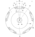
- FIG. 2 is a sectional view showing the rotor 1.
- the rotor 1 has a rotating shaft 40, an annular rotor core 10 surrounding the rotating shaft 40 from the outside in the radial direction, and a resin portion 30 provided therebetween.
- the rotating shaft 40 is a shaft whose central axis is the axis line Ax.
- the rotating shaft 40 is made of metal such as iron, nickel (Ni), or chromium (Cr).
- the resin portion 30 supports the rotor core 10 with respect to the rotating shaft 40 and is made of a non-magnetic material, more specifically a thermoplastic resin such as PBT.
- the resin portion 30 is formed by molding the rotor core 10 and the rotating shaft 40 with resin.
- a rib or a hollow portion may be provided in the resin portion 30 .
- the rotating shaft 40 may be fitted into a shaft hole formed in the rotor core 10 instead of providing the resin portion 30 .
- the rotor core 10 is made by laminating magnetic lamination elements in the axial direction and fixing them by caulking or the like.
- the laminated elements are iron-based core materials, for example electrical steel sheets.
- the thickness of the laminate element is, for example, 0.2-0.5 mm.
- Both the outer circumference 10a and the inner circumference 10b of the rotor core 10 extend in the circumferential direction around the axis Ax.
- a plurality of magnet insertion holes 11 are formed along the outer circumference 10 a of the rotor core 10 .
- the magnet insertion holes 11 are arranged at regular intervals in the circumferential direction.
- the magnet insertion hole 11 extends from one axial end to the other axial end of the rotor core 10 .
- the magnet insertion hole 11 extends linearly in a direction orthogonal to a straight line passing through the center in the circumferential direction and the axis Ax (that is, a pole center line C1 to be described later).
- the number of magnet insertion holes 11 is five here.
- a permanent magnet 20 is arranged in each magnet insertion hole 11 .
- the permanent magnet 20 is flat, has a width in the circumferential direction, and has a thickness in the radial direction. Also, the permanent magnet 20 is magnetized in the thickness direction.
- the permanent magnet 20 is composed of, for example, a rare earth magnet whose main component is neodymium (Nd) or samarium (Sm). Alternatively, a ferrite magnet containing iron as a main component may be used.
- the permanent magnet 20 forms a magnet pole P1.
- the permanent magnets 20 have magnetic pole surfaces of the same polarity (for example, N pole) directed toward the outer circumference 10 a of the rotor core 10 . Therefore, between the permanent magnets 20 adjacent to each other in the rotor core 10, a virtual magnetic pole P2 having a polarity opposite to that of the permanent magnets 20 (for example, S pole) is formed.
- the rotor 1 alternately has five magnet magnetic poles P1 and five virtual magnetic poles P2 in the circumferential direction. Therefore, the rotor 1 has ten poles. Such a rotor structure is called a consequent pole type.
- the number of poles of the rotor 1 is not limited to 10, and may be an even number.
- the number of magnet poles P1 is expressed by N/2
- the number of virtual magnetic poles P2 is also expressed by N/2.
- the magnet pole P1 is also referred to as the first magnetic pole and the virtual magnetic pole P2 is also referred to as the second magnetic pole.
- one permanent magnet 20 is arranged in each magnet insertion hole 11, and the one permanent magnet 20 constitutes the magnet magnetic pole P1.
- two or more permanent magnets may be arranged in each magnet insertion hole 11, and the two or more permanent magnets may constitute the magnet magnetic pole P1 (see FIGS. 10 and 11).
- the permanent magnet 20 does not necessarily have to be flat.
- the center of the magnet magnetic pole P1 in the circumferential direction is the pole center of the magnet magnetic pole P1.
- a straight line passing through the pole center of the magnet magnetic pole P1 and the axis Ax is referred to as a pole center line C1.
- the center of the virtual magnetic pole P2 in the circumferential direction is the pole center of the virtual magnetic pole P2.
- a straight line passing through the pole center of the virtual magnetic pole P2 and the axis Ax is referred to as a pole center line C2.
- the outer circumference 10a of the rotor core 10 has a shape in which the outer diameter is the largest at the pole center of the magnetic poles P1 and P2 and the outer diameter is the smallest at the interpolar portion between the magnetic poles P1 and P2, that is, a flower-shaped shape.
- the shape of the outer periphery 10a of the rotor core 10 is not limited to the flower-round shape, and may be, for example, a circular shape.
- the magnetic flux passing through the virtual magnetic pole P2 easily flows to the rotating shaft 40.
- the resin portion 30 arranged between the rotor core 10 and the rotating shaft 40 has the effect of suppressing magnetic flux leakage to the rotating shaft 40 .
- a flux barrier 12 which is a gap, is formed at both ends of the magnet insertion hole 11 in the circumferential direction.
- a thin portion is formed between the outer periphery 10 a of the rotor core 10 and the flux barrier 12 .
- the thickness of the thin portion in the radial direction is desirably equal to the thickness of the laminated elements of the rotor core 10 in order to suppress leakage flux between adjacent magnetic poles.
- the virtual magnetic poles P2 described above are formed between the flux barriers 12 of the adjacent magnet insertion holes 11 . That is, the flux barrier 12 defines both circumferential ends of the virtual magnetic pole P2. Therefore, the above-described pole center line C2 of the virtual magnetic pole P2 is a straight line that passes through the circumferential intermediate position of the two flux barriers 12 on both sides of the virtual magnetic pole P2 and the axis Ax.
- FIG. 3 is a cross-sectional view showing the rotor 1 in an enlarged manner. 3 and FIGS. 4 to 8 and 10 to 13 described later, the hatching of the rotor core 10 and the resin portion 30 is omitted.
- the permanent magnet 20 has a magnetic pole face 20a on the outer circumference 10a side, a magnetic pole face 20b on the inner circumference 10b side, and end faces 20c on both sides in the circumferential direction. Both of the magnetic pole faces 20a and 20b extend in a direction orthogonal to the pole centerline C1.
- the magnet insertion hole 11 has an outer edge 11a on the side of the outer periphery 10a and an inner edge 11b on the side of the inner periphery 10b. Both the outer edge 11a and the inner edge 11b extend in a direction perpendicular to the pole centerline C1. Stepped portions 11 c are formed at both ends of the inner edge 11 b of the magnet insertion hole 11 .
- the outer edge 11 a of the magnet insertion hole 11 faces the magnetic pole face 20 a of the permanent magnet 20
- the inner edge 11 b of the magnet insertion hole 11 faces the magnetic pole face 20 b of the permanent magnet 20
- the two stepped portions 11 c of the magnet insertion hole 11 face both end faces 20 c of the permanent magnet 20 .
- the flux barrier 12 includes an outer edge 12a extending along the outer circumference 10a of the rotor core 10, a side edge 12b that is an edge on the side of the virtual magnetic pole P2, and extending between the side edge 12b and the stepped portion 11c. and a proximal edge 12c present.
- a slit 13 as a non-magnetic portion is formed between the magnet insertion hole 11 and the outer circumference 10a of the rotor core 10 in the radial direction.
- two slits 13 are formed on both sides of the pole centerline C1.
- the slit 13 extends in the circumferential direction.
- the slit 13 is desirably formed continuously with the flux barrier 12 on the pole center line C1 side of the flux barrier 12 .
- An example in which the slit 13 is formed apart from the flux barrier 12 will be described with reference to FIGS.
- a corner portion R1 is defined as a corner portion between the magnetic pole face 20a and the end face 20c of the permanent magnet 20 on one side (the left side in FIG. 3) of the pole center line C1 of each magnet magnetic pole P1.
- a corner portion R2 is defined as a corner portion between the magnetic pole surface 20a and the end surface 20c of the permanent magnet 20 on the other side (the right side in FIG. 3) of the pole center line C1.
- the corner R1 corresponds to the corner facing the outer circumference 10a of the rotor core 10 and furthest from the pole center line C1 on one side of the pole center line C1.
- the corner R2 corresponds to a corner of the permanent magnet 20 facing the outer circumference 10a of the rotor core 10 and furthest from the pole center line C1 on the other side of the pole center line C1.
- Both the corners R1 and R2 of the permanent magnet 20 are positioned within the space surrounded by the outer edge 12a, the side edge 12b and the base edge 12c of the flux barrier 12.
- the corner R1 is also called the first corner
- the corner R2 is also called the second corner.
- FIG. 4 is a diagram for explaining the arrangement of the magnet magnetic poles P1 and the virtual magnetic poles P2 of the rotor 1.
- FIG. A straight line passing through the corner R1 of the permanent magnet 20 and the axis Ax is defined as a straight line L1.
- a straight line passing through the corner R2 of the permanent magnet 20 and the axis Ax is defined as a straight line L2.
- the angle between the straight line L1 and the straight line L2 be the angle ⁇ m.
- the angle .theta.m represents the range occupied by the permanent magnet 20 in the circumferential direction.
- the angle ⁇ m satisfies ⁇ m ⁇ 360/N.
- N the number of poles of the rotor 1
- the angle ⁇ m should be 36 [degrees] or more.
- the angle ⁇ m is, for example, 40 degrees.
- the range occupied by the permanent magnet 20 is equal to or greater than the angle obtained by equally dividing 360 [degrees] by the number of poles N (that is, 360/N [degrees]).
- a point R3 is the point closest to the outer circumference 10a of the side edge 12b of one of the two flux barriers 12 that are circumferentially adjacent to each other with the virtual magnetic pole P2 interposed therebetween.
- the point closest to the outer circumference 10a of the side edge 12b of the other flux barrier 12 is defined as a point R4.
- a straight line passing through the point R3 and the axis Ax is assumed to be a straight line L3, and a straight line passing through the point R4 and the axis Ax is assumed to be a straight line L4.
- the angle formed by the straight lines L3 and L4 is assumed to be an angle ⁇ v.
- the angle ⁇ v represents the range occupied by the virtual magnetic pole P2 in the circumferential direction.
- the angle ⁇ v satisfies ⁇ v ⁇ 360/N and also satisfies ⁇ v ⁇ m.
- the angle ⁇ v is, for example, 30 degrees. That is, the angle ⁇ v occupied by the virtual magnetic pole P2 is smaller than the angle ⁇ m occupied by the permanent magnet 20 .
- the one flux barrier 12 is also called a first gap, and the other flux barrier 12 is also called a second gap.
- Point R3 is also referred to as the third point, and point R4 is also referred to as the fourth point.
- FIG. 5(A) is an enlarged view of the magnetic pole P1 of the magnet.
- FIG. 5B is an enlarged view of a region including the end of the permanent magnet 20.
- slits 13 are formed on both sides of the pole center line C1 of the magnet magnetic pole P1. The area between two slits 13 is also called inter-slit area.
- the slit 13 includes an outer edge 13a extending along the outer periphery 10a of the rotor core 10, an inner edge 13b facing the outer edge 13a in the radial direction, and a tip edge formed on the pole center line C1 side. 13c.
- the outer edge 13a of the slit 13 here extends on the extension line of the outer edge 12a of the flux barrier 12 .
- a curved portion 13 d is formed between the inner edge 13 b of the slit 13 and the outer edge 11 a of the magnet insertion hole 11 .
- the slit 13 has a length A in the circumferential direction and a width B in the radial direction, and the relationship between the length A and the width B is A>B.
- the length A is the distance from the tip edge 13c of the slit 13 to the curved portion 13d.
- the width B is the distance between the outer edge 13a and the inner edge 13b.
- a core region 14 is formed between the inner edge 13 b of the slit 13 and the outer edge 11 a of the magnet insertion hole 11 .
- the core region 14 constitutes part of the magnetic path from the permanent magnet 20 to the inter-slit region.
- the core region 14 has a width W in the radial direction. The width W is the radial distance between the inner edge 13 b of the slit 13 and the outer edge 11 a of the magnet insertion hole 11 .
- the inner edge 13b of the slit 13 extends along the outer periphery 10a of the rotor core 10, the distance from the outer edge 11a of the magnet insertion hole 11 increases as it approaches the pole center line C1. Therefore, the radial width W of the core region 14 increases as it approaches the pole centerline C1.
- the point closest to the outer circumference 10a at the leading end edge 13c of one of the two slits 13 of the magnet magnetic pole P1 is defined as a point R5.
- the point closest to the outer periphery 10a at the tip edge 13c of the other slit 13 is defined as a point R6.
- a straight line passing through the point R5 and the axis Ax is assumed to be a straight line L5, and a straight line passing through the point R5 and the axis Ax is assumed to be a straight line L6.
- the angle formed by these straight lines L5 and L6 is defined as angle ⁇ s.
- the angle .theta.s represents the range occupied by the inter-slit region in the circumferential direction.
- the angle ⁇ s is smaller than the above angle ⁇ m, and therefore satisfies ⁇ s ⁇ m and also satisfies ⁇ s ⁇ 360/N [degrees].
- the angle ⁇ s is, for example, 25 degrees.
- the one slit 13 is also called a first non-magnetic portion, and the other slit 13 is also called a second non-magnetic portion.
- the point R5 is also called the first point and the point R6 is also called the second point.
- Embodiment 1 Next, the operation of Embodiment 1 will be described. As the area of the magnetic pole surface 20a of the permanent magnet 20 increases, the amount of magnetic flux emitted from the magnetic pole surface 20a increases and the magnetic force increases. However, if the axial length of the permanent magnet 20 is lengthened, the axial length of the electric motor 2 is lengthened, leading to an increase in the size of the electric motor 2 or an increase in manufacturing cost. Therefore, it is desirable to increase the area of the magnetic pole face 20a of the permanent magnet 20 per unit length in the axial direction.
- the angle ⁇ m occupied by the permanent magnet 20 is 360/N [degree] or more. Therefore, the width of the pole face 20a of the permanent magnet 20 can be widened, and the area of the pole face 20a of the permanent magnet 20 per unit length in the axial direction can be increased. Thereby, the amount of magnetic flux emitted from the magnetic pole face 20a can be increased, and the magnetic force of the permanent magnet 20 can be increased.
- the rotor 1 of Embodiment 1 is of the consequent pole type, and no permanent magnets are arranged in the virtual magnetic poles P2. Therefore, it is possible to set the angle ⁇ m occupied by the permanent magnet 20 to 360/N [degree] or more.
- the output of the electric motor 2 can be increased while suppressing an increase in the manufacturing cost of the electric motor 2.
- the axial length of the electric motor 2 required to obtain the same magnetic force can be shortened.
- the core material of rotor core 10 and stator core 50 can be reduced, and the total length of coil 55 can be shortened. That is, the manufacturing cost of the electric motor 2 can be reduced, and efficiency can be improved.
- the angle ⁇ m of the permanent magnets 20 exceeds 720/N [degrees], a space for forming the virtual magnetic poles P2 cannot be secured between the adjacent permanent magnets 20 . Therefore, the angle ⁇ m is set so as to satisfy 360/N [degrees] ⁇ m ⁇ 720/N [degrees].
- the angle ⁇ m occupied by the permanent magnet 20 becomes larger than the angle ⁇ v occupied by the virtual magnetic pole P2 (that is, ⁇ m> ⁇ v). Therefore, if the magnet magnetic pole P1 is assumed to be the north pole and the virtual magnetic pole P2 is assumed to be the south pole, the width of the north pole on the surface of the rotor 1 is wider than the width of the south pole.
- the rotor 1 of Embodiment 1 has two slits 13 that limit the magnetic path on both sides of the pole center line C1 of the magnet magnetic pole P1.
- the slit 13 is long in the circumferential direction. This is a shape suitable for controlling the flow of magnetic flux.
- FIG. 6 is a schematic diagram for explaining the flow of magnetic flux in the magnet magnetic pole P1 and the virtual magnetic pole P2 of the rotor 1.
- FIG. Here, the magnetic pole surface 20a of the permanent magnet 20 of the magnet magnetic pole P1 is assumed to be the N pole.
- the magnetic flux emitted from the magnetic pole faces 20a of the permanent magnets 20 is directed toward the outer circumference 10a of the rotor core 10.
- the slit 13 formed on the side of the outer periphery 10a of the magnet insertion hole 11 prevents passage of magnetic flux because the inside thereof is air or other non-magnetic material.
- the magnetic flux emitted from the magnetic pole surface 20a of the permanent magnet 20 passes through the area between the two slits 13, that is, the inter-slit area, toward the stator 5.
- the angle occupied by the inter-slit region is the above angle ⁇ s.
- This angle ⁇ s is smaller than the angle ⁇ m occupied by the permanent magnets 20 . That is, the slit 13 has a role of restricting the flow of the magnetic flux emitted from the magnetic pole surface 20a of the permanent magnet 20. As shown in FIG.
- the widths of the north and south poles on the surface of the rotor 1 can be brought closer to each other. This can reduce vibration and noise caused by the difference in width between the N pole and the S pole.
- the amount of core of the virtual magnetic pole P2 is equal to the amount of core of the magnetic pole P1. , and therefore the magnetic attraction force between the rotor 1 and the stator 5 becomes large at the virtual magnetic pole P2.
- the amount of core is the amount of core material such as an electromagnetic steel sheet.
- the core amount of the magnet magnetic pole P1 and the core amount of the virtual magnetic pole P2 can be brought closer, and vibration caused by the difference in magnetic attraction force can be reduced.
- the number of slits 13 may be one because even one slit 13 can limit the magnetic path.
- the core region 14 shown in FIG. 5(B) constitutes a part of the magnetic path from the magnetic pole face 20a of the permanent magnet 20 to the region between the slits.
- the core region 14 shown in FIG. 5(B) constitutes a part of the magnetic path from the magnetic pole face 20a of the permanent magnet 20 to the region between the slits.
- the radial width W of the core region 14 becomes wider as it approaches the pole center line C1, it is possible to suppress local concentration of magnetic flux and magnetic saturation caused thereby. Thereby, the magnetic flux of the permanent magnet 20 can be effectively used.
- FIG. 7 is a cross-sectional view showing another configuration example of the rotor 1.
- FIG. 8 is an enlarged view of the magnetic pole P1 of the rotor 1 of FIG.
- slits 15 are formed on both sides of the pole center line C1 of each magnet magnetic pole P1, and each slit 15 is formed away from the flux barrier 12.
- the slit 15 includes an outer edge 15a on the outer periphery 10a side of the rotor core 10, an inner edge 15b on the magnet insertion hole 11 side, a tip edge 15c on the pole center line C1 side, and the flux barrier 12 side proximal edge 15d.
- the length A in the circumferential direction and the width B in the radial direction of the slit 15 have a relation of A>B.
- Each slit 15 functions to restrict the magnetic path of the magnet magnetic pole P1, and an inter-slit region is formed between two slits 15.
- the angle occupied by the inter-slit region is the above angle ⁇ s.
- a bridge portion 16 is formed between the slit 15 and the flux barrier 12 .
- the magnetic flux emitted from the magnetic pole surface 20a of the permanent magnet 20 passes through not only the inter-slit region but also the bridge portion 16. That is, the function of restricting the magnetic path of the magnet magnetic pole P1 is reduced by the magnetic flux flowing through the bridge portion 16 .
- the slits 13 when the slits 13 are formed continuously in the flux barrier 12 as shown in FIGS. , the slit 13 can effectively exhibit the function of limiting the magnetic path of the magnet pole P1.
- the magnetic pole P1 of the magnet is the N pole
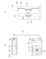
- FIG. 9 is a longitudinal sectional view showing a molded electric motor to which the electric motor 2 of Embodiment 1 is applied.
- the stator 5 is covered with a molded resin portion 60 to form a molded stator 6 .
- the mold resin portion 60 is made of a thermosetting resin such as BMC (bulk molding compound), for example.
- the mold resin portion 60 has an opening 61 on the left side in FIG. 9 and a bearing support portion 62 on the opposite side.
- the rotor 1 is inserted into the inner hollow portion of the stator 5 through the opening 61 .
- a metal bracket 44 is attached to the opening 61 of the mold resin portion 60 .
- This bracket 44 holds the bearing 41 .
- a cap 43 is attached to the outside of the bracket 44 to prevent water or the like from entering the bearing 41 .
- the bearing 42 is held by the bearing support portion 62 .
- a rotary shaft 40 is supported by the bearings 41 and 42 .
- the rotating shaft 40 protrudes from the stator 5 to the left in FIG. 9, and an impeller of a blower, for example, is attached to the tip 40a thereof. Therefore, the protruding side (left side in FIG. 9) of the rotating shaft 40 is called “load side”, and the opposite side (right side in FIG. 9) is called “counter-load side”.
- a circuit board 70 is arranged on the anti-load side of the stator 5 .
- a magnetic sensor 71 and a drive circuit 72 for driving the electric motor 2 are mounted on the circuit board 70, and lead wires 73 are wired.
- the lead wires 73 include power lead wires for supplying power to the coils 55 of the stator 5 and sensor lead wires for transmitting signals from the magnetic sensor 71 to the outside.
- a lead wire lead-out component 74 for drawing out the lead wire 73 to the outside is attached to the outer peripheral portion of the mold resin portion 60 .
- the resin portion 30 of the rotor 1 is provided between the rotor core 10 and the rotary shaft 40 and also covers both axial end surfaces of the rotor core 10 .
- a sensor magnet 17 is arranged on the anti-load side of the rotor core 10 and held by a resin portion 30 .
- the sensor magnet 46 is an annular magnet and has the same magnetic poles as the rotor 1 .
- a magnetic sensor 71 mounted on the circuit board 70 is composed of, for example, a Hall IC, and detects the magnetic flux of the sensor magnet 46 .
- the drive circuit 72 detects the rotational position of the rotor 1 based on the detection signal from the magnetic sensor 71 and controls the current flowing through the coil 55 .
- sensorless control may be performed to estimate the rotational position of the rotor 1 from the current flowing through the coil 55 or the like.
- stator 5 is covered with the molded resin portion 60 here, the stator 5 may be fitted inside a metal shell.
- the rotor 1 of the first embodiment has the rotor core 10 and the permanent magnets 20.
- the permanent magnets 20 form N/2 (N is an even number) magnetic poles P1.
- N/2 virtual magnetic poles P2 are formed.
- the permanent magnet 20 has a corner portion R1 facing the outer circumference 10a of the rotor core 10 and furthest to one side from the pole center line C1, and a corner R1 facing the outer circumference 10a of the rotor core 10 and furthest to the other side from the pole center line C1. and a corner R2.
- An angle ⁇ m between a straight line L1 passing through the corner R1 and the axis Ax and a straight line L2 passing through the corner R2 and the axis Ax satisfies ⁇ m ⁇ 360/N degrees.
- the area of the magnetic pole faces 20a of the permanent magnets 20 per unit length in the axial direction can be increased, and the magnetic force of the permanent magnets 20 can be increased. That is, it is possible to increase the output and improve the efficiency while suppressing an increase in the manufacturing cost of the electric motor 2 .
- slits 13 are formed as non-magnetic portions extending in the circumferential direction between the permanent magnets 20 and the outer periphery 10a of the rotor core 10, the magnetic paths of the magnet magnetic poles P1 can be restricted. As a result, the difference in width between the N pole and the S pole on the surface of the rotor 1 can be suppressed, and vibration and noise can be reduced.
- the slit 13 is formed continuously with the magnet insertion hole 11, compared with the case where the slit 13 is formed away from the magnet insertion hole 11, the effect of limiting the magnetic path of the magnetic pole P1 of the magnet is reduced. can be enhanced.
- the core region 14 is formed between the slit 13 and the magnet insertion hole 11, and the width W of the core region 14 increases as the width W of the core region 14 approaches the pole center line C1, the distance from the magnetic pole surface 20a of the permanent magnet 20 to the region between the slits increases. can suppress the occurrence of magnetic saturation in the magnetic path of
- the point closest to the outer periphery 10a of the leading edge 13c of one slit 13 is defined as a point R5
- the point closest to the outer periphery 10a of the leading edge 13c of the other slit 13 is defined as R5.
- an angle ⁇ s formed by a straight line L5 passing through the point R5 and the axis Ax and a straight line L6 passing through the point R6 and the axis Ax satisfies ⁇ s ⁇ 360/N [degrees]. Therefore, the widths of the N poles and S poles on the surface of the rotor 1 can be brought closer to each other, and vibration and noise can be reduced.
- a point R3 is the point closest to the outer circumference 10a of the side edge 12b of one of the flux barriers 12 on both sides in the circumferential direction of the virtual magnetic pole P2.
- a point near the outer circumference 10a is a point R4
- an angle ⁇ v between a straight line L4 passing through the point R3 and the axis Ax and a straight line L4 passing through the point R4 and the axis Ax satisfies ⁇ v ⁇ s. Therefore, the widths of the north and south poles on the surface of the rotor 1 can be brought closer to each other, and variations in the magnetic attraction force between the rotor 1 and the stator 5 can be reduced, thereby reducing vibration and noise.
- FIG. 10 is a cross-sectional view showing a rotor 1A of Modification 1. As shown in FIG. In the rotor 1 of Embodiment 1 described above, one permanent magnet 20 is inserted into each magnet insertion hole 11 . On the other hand, in the rotor 1 ⁇ /b>A of Modification 1, two permanent magnets 21 and 22 are inserted into each magnet insertion hole 11 .
- the rotor core 10 of the rotor 1A has N/2 magnet insertion holes 11 formed therein.
- the magnet insertion hole 11 has a V shape in which the center in the circumferential direction protrudes toward the inner circumference 10 b of the rotor core 10 .
- Permanent magnets 21 are arranged on one side of the magnet insertion hole 11 and permanent magnets 22 are arranged on the other side of the magnet insertion hole 11 across the center in the circumferential direction.
- the permanent magnet 21 is also called the first permanent magnet and the permanent magnet 22 is also called the second permanent magnet.
- the permanent magnet 21 has a magnetic pole face 21a on the outer circumference 10a side, a magnetic pole face 21b on the inner circumference 10b side, and end faces 21c on both ends in the circumferential direction.
- the permanent magnet 22 has a magnetic pole face 22a on the side of the outer circumference 10a, a magnetic pole face 22b on the side of the inner circumference 10b, and end faces 22c on both ends in the circumferential direction.
- the magnet insertion hole 11 has an outer edge 11a on the side of the outer circumference 10a and an inner edge 11b on the side of the inner circumference 10b. There is Stepped portions 11c are formed on both circumferential sides of the inner edge 11b.
- the outer edge 11a of the magnet insertion hole 11 faces the magnetic pole faces 21a and 22a of the permanent magnets 21 and 22.
- An inner edge 11b of the magnet insertion hole 11 faces the magnetic pole faces 21b and 22b of the permanent magnets 21 and 22, respectively.
- the stepped portion 11c of the magnet insertion hole 11 faces the end faces 21c, 22c of the permanent magnets 21, 22 on the side away from the pole center line C1.
- the permanent magnets 21 and 22 arranged in each magnet insertion hole 11 form a magnet magnetic pole P1 as a first magnetic pole.
- a virtual magnetic pole P2 as a second magnetic pole is formed between the adjacent magnet magnetic poles P1.
- the pole center line C1 is a straight line that passes through the circumferential center of the magnet magnetic pole P1, that is, the circumferential center of the magnet insertion hole 11, and the axis Ax.
- the pole center line C2 is a straight line passing through the center of the virtual magnetic pole P2 in the circumferential direction and the axis Ax.
- corner R1 the corner between the magnetic pole face 21a and the end face 21c on the side away from the pole center line C1 is defined as corner R1.
- corner R2 the corner between the magnetic pole face 22a and the end face 22c on the side away from the pole center line C1 is defined as corner R2.
- Both the corners R1 and R2 of the permanent magnets 21 and 22 are located inside the flux barrier 12 .
- the corner R1 corresponds to the corner facing the outer circumference 10a of the rotor core 10 and furthest from the pole center line C1 on one side (the left side in FIG. 10) of the pole center line C1.
- the corner R2 corresponds to the corner facing the outer circumference 10a of the rotor core 10 and furthest from the pole center line C1 on the other side (the right side in FIG. 10) of the pole center line C1.
- An angle ⁇ m is defined by a straight line L1 passing through the corner R1 of the permanent magnet 20 and the axis Ax and a straight line L2 passing through the corner R2 and the axis Ax.
- the angle .theta.m represents the range occupied by the permanent magnets 21 and 22 in the circumferential direction.
- the angle ⁇ m satisfies ⁇ m ⁇ 360/N. Since the angle ⁇ m is 360/N [degrees] or more, the areas of the magnetic pole faces 21a, 22a of the permanent magnets 21, 22 per unit length in the axial direction can be increased.
- the formation of the slit 13 on the side of the outer circumference 10a of the magnet insertion hole 11 is the same as in the first embodiment. Also, the angle ⁇ s of the inter-slit region and the angle ⁇ v of the virtual magnetic pole P2 are as described in the first embodiment.
- the rotor 1A of Modification 1 is configured in the same manner as the rotor 1 of Embodiment 1.
- two permanent magnets 21 and 22 may be arranged in the straight magnet insertion hole 11 .
- the angle ⁇ m occupied by the permanent magnets 21 and 22 is set to 360/N degrees or more.
- the area of the magnetic pole faces 21a, 22a of the permanent magnets 21, 22 per unit length in the axial direction can be increased, and the magnetic force can be increased.
- FIG. 11 is a cross-sectional view showing a rotor 1B of Modification 2. As shown in FIG. In the rotor 1 of Embodiment 1 described above, one permanent magnet 20 is inserted into each magnet insertion hole 11 . On the other hand, in the rotor 1 ⁇ /b>B of Modification 2, three permanent magnets 23 , 24 , 25 are inserted into each magnet insertion hole 11 .
- the rotor core 10 of the rotor 1B has N/2 magnet insertion holes 11 formed therein.
- Magnet insertion hole 11 has a central portion located in the center in the circumferential direction, and two inclined portions extending from both ends of the central portion toward outer periphery 10 a of rotor core 10 .
- the two sloped portions are sloped such that the distance between the two sloped portions widens with increasing distance from the central portion. In other words, the magnet insertion hole 11 has a bathtub shape.
- a permanent magnet 23 is arranged in the central portion of the magnet insertion hole 11, and permanent magnets 24 and 25 are arranged in the two inclined portions. Both the permanent magnets 24 and 25 are inclined so that the distance between the two permanent magnets 24 and 25 widens as the distance from the permanent magnet 23 increases. In other words, the permanent magnets 23, 24, 25 are arranged like a bathtub.
- the permanent magnet 23 is also referred to as a first permanent magnet, the permanent magnet 24 as a second permanent magnet, and the permanent magnet 25 as a third permanent magnet.
- the permanent magnet 23 has a magnetic pole face 23a on the outer circumference 10a side, a magnetic pole face 23b on the inner circumference 10b side, and end faces 23c on both ends in the circumferential direction.
- the permanent magnet 24 has a magnetic pole face 24a on the pole center side, a magnetic pole face 24b on the opposite side, and end faces 24c on both ends in the circumferential direction.
- the permanent magnet 25 has a magnetic pole face 25a on the pole center side, a magnetic pole face 25b on the opposite side, and end faces 25c on both ends in the circumferential direction.
- the magnet insertion hole 11 has an outer edge 11a on the side of the outer periphery 10a and an inner edge 11b on the side of the inner periphery 10b.
- the outer edge 11a of the magnet insertion hole 11 faces the magnetic pole faces 23a, 24a, 25b of the permanent magnets 23, 24, 25.
- the inner edge 11b of the magnet insertion hole 11 faces the magnetic pole faces 23b, 24b, 25b of the permanent magnets 23, 24, 25.
- a stepped portion for positioning the permanent magnets 23 , 24 , 25 may be provided in the magnet insertion hole 11 .
- the permanent magnets 23, 24, and 25 arranged in each magnet insertion hole 11 form a magnet magnetic pole P1 as a first magnetic pole.
- a virtual magnetic pole P2 as a second magnetic pole is formed between the adjacent magnet magnetic poles P1.
- the pole center line C1 is a straight line that passes through the circumferential center of the magnet magnetic pole P1, that is, the circumferential center of the magnet insertion hole 11, and the axis Ax.
- the pole center line C2 is a straight line passing through the center of the virtual magnetic pole P2 in the circumferential direction and the axis Ax.
- corner R1 the corner between the magnetic pole face 24a and the end face 24c on the side away from the pole center line C1 is defined as corner R1.
- corner R2 the corner between the magnetic pole face 25a and the end face 25c on the side away from the pole center line C1 is defined as corner R2.
- Both the corners R1 and R2 of the permanent magnets 24 and 25 are located within the flux barrier 12 .
- the corner R1 corresponds to the corner facing the outer circumference 10a of the rotor core 10 and furthest from the pole center line C1 on one side of the pole center line C1.
- the corner R2 corresponds to the corner facing the outer circumference 10a of the rotor core 10 and furthest from the pole centerline C1 on the other side of the pole centerline C1.
- An angle ⁇ m is defined by a straight line L1 passing through the corner R1 of the permanent magnet 20 and the axis Ax and a straight line L2 passing through the corner R2 and the axis Ax.
- the angle .theta.m represents the range occupied by the permanent magnets 23, 24, 25 in the circumferential direction.
- the angle ⁇ m satisfies ⁇ m ⁇ 360/N. Since the angle ⁇ m is 360/N [degree] or more, the areas of the magnetic pole faces 23a, 24a, 25a of the permanent magnets 23, 24, 25 per unit length in the axial direction can be increased.
- the formation of the slit 13 on the side of the outer circumference 10a of the magnet insertion hole 11 is the same as in the first embodiment. Also, the angle ⁇ s of the inter-slit region and the angle ⁇ v of the virtual magnetic pole P2 are as described in the first embodiment.
- the rotor 1B of Modification 2 is configured in the same manner as the rotor 1 of Embodiment 1.
- the three permanent magnets 23, 24, and 25 may be arranged in the linear magnet insertion hole 11.
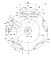
- FIG. 12 is a sectional view showing the rotor 1C of the second embodiment.
- the circumferential width of the virtual magnetic pole P2 differs between the radially outer side and the radially inner side.
- the rotor core 10 of the rotor 1C has N/2 magnet insertion holes 11 formed therein.
- the shape of the magnet insertion hole 11 is as described in the first embodiment.
- One permanent magnet 20 is arranged in each magnet insertion hole 11 .
- Flux barriers 12 are formed as air gaps at both circumferential ends of each magnet insertion hole 11 .
- FIG. 13 is an enlarged view showing a part of the rotor 1C. As shown in FIG. 13, flux barriers 12 are formed on both sides of the virtual magnetic pole P2. The flux barrier 12 is also a portion that defines both circumferential ends of the virtual magnetic pole P2.
- the flux barrier 12 includes an outer edge 12a extending along the outer circumference 10a of the rotor core 10, a side edge 12b that is an edge on the side of the virtual magnetic pole P2, and extending between the side edge 12b and the stepped portion 11c. and a proximal edge 12c present.
- a point R3 is the point closest to the outer circumference 10a of the side edge 12b of one of the two flux barriers 12 adjacent to each other with the virtual magnetic pole P2 interposed therebetween.
- the point closest to the outer circumference 10a of the side edge 12b of the other flux barrier 12 is defined as a point R4.
- the point closest to the inner circumference 10b of the side edge 12b of the one flux barrier 12 is defined as a point R7.
- the point closest to the inner circumference 10b of the side edge 12b of the other flux barrier 12 is defined as a point R8.
- distance E1 be the distance in the circumferential direction between point R3 and point R4.
- the distance in the circumferential direction between points R7 and R8 is defined as distance E2.
- the distance E1 and the distance E2 have a relationship of E1>E2.
- the distance E1 corresponds to the radially outer width of the virtual magnetic pole P2
- the distance E2 corresponds to the radially inner width of the virtual magnetic pole P2. Therefore, the relationship of E1>E2 means that the width of the virtual magnetic pole P2 in the circumferential direction is wider at the radially outer side than at the radially inner side.
- a straight line passing through the point R3 and the axis Ax is defined as a straight line L3
- a straight line passing through the point R4 and the axis Ax is defined as a straight line L4.
- the angle formed by the straight lines L3 and L4 is assumed to be an angle ⁇ v1.
- This angle ⁇ v1 is an angle corresponding to the above distance E1.
- a straight line passing through the point R7 and the axis Ax is called a straight line L7
- a straight line passing through the point R8 and the axis Ax is called a straight line L8.
- the angle formed by the straight line L7 and the straight line L8 is assumed to be an angle ⁇ v2.
- This angle ⁇ v2 is an angle corresponding to the above distance E2.
- Both the angle ⁇ v1 and the angle ⁇ v2 are less than 360/N [degree]. Further, the angle ⁇ v1 and the angle ⁇ v2 have a relationship of ⁇ v1> ⁇ v2. This corresponds to the above relationship of E1>E2.
- the distance E1 which is the radially outer width of the virtual magnetic pole P2 is greater than the distance E2, which is the radially inner width.
- the slit 13 between the magnet insertion hole 11 and the outer circumference 10a of the rotor core 10 and the inter-slit region are as described in the first embodiment. It is desirable that the angle ⁇ s of the inter-slit region be equal to or greater than the angle ⁇ v1, that is, ⁇ v1 ⁇ s. As a result, the difference in width between the N pole and the S pole on the surface of the rotor 1C can be reduced, and vibration caused by the difference in magnetic attraction force can be reduced.
- the rotor 1C of Embodiment 2 is configured in the same manner as the rotor 1 of Embodiment 1 except for the points described above.
- the circumferential distance between the flux barriers 12 on both sides of the virtual magnetic pole P2 is wider on the radial outer side than on the radial inner side. Therefore, it is possible to increase the magnetic force by increasing the area of the magnetic pole faces 20a of the permanent magnets 20 while reducing the difference in width between the N pole and the S pole on the surface of the rotor 1C. It is possible to increase the output and improve efficiency while suppressing an increase in the manufacturing cost of the electric motor 2 .
- FIG. 14(A) is a diagram showing the configuration of an air conditioner 500 to which the electric motor 2 of Embodiment 1 is applied.
- An air conditioner 500 includes an outdoor unit 501 and an indoor unit 502 .
- the outdoor unit 501 and the indoor unit 502 are connected by a refrigerant pipe 503 .
- the outdoor unit 501 includes an outdoor fan 510 such as a propeller fan
- the indoor unit 502 includes an indoor fan 520 such as a cross-flow fan.
- the outdoor fan 510 has an impeller 511 and an electric motor 2A for driving the same.
- the indoor fan 520 has an impeller 521 and an electric motor 2B that drives it. Both the electric motors 2A and 2B are configured with the electric motor 2 described in the first embodiment.
- FIG. 14A also shows a compressor 504 that compresses the refrigerant.
- FIG. 14(B) is a cross-sectional view of the outdoor unit 501.
- the electric motor 2A is supported by a frame 509 arranged inside the housing 508 of the outdoor unit 501 .
- An impeller 511 is attached via a hub 512 to the rotary shaft 40 of the electric motor 2A.
- the impeller 511 is rotated by the electric motor 2A to blow air outdoors.
- the heat released when the refrigerant compressed by the compressor 504 is condensed by the condenser (not shown) is released to the outside by the outdoor fan 510.
- the impeller 521 is rotated by the electric motor 2B to blow air into the room.
- the indoor blower 520 blows air into the room from which heat has been removed when the refrigerant evaporates in an evaporator (not shown).
- the electric motors 2A and 2B are configured with the electric motor 2 of Embodiment 1, a higher output can be obtained. Therefore, the operating efficiency of outdoor fan 510 and indoor fan 520 can be improved.
- the electric motors 2A and 2B are not limited to the electric motor 2 of the first embodiment, and may have the electric motors of the second embodiment or each modification. Moreover, although the electric motors of the respective embodiments and modifications are used for both the outdoor fan 510 and the indoor fan 520 here, they may be used for only one of them.
- the electric motor 2 described in each embodiment is not limited to a blower, and may be used as a compressor of an air conditioner. may be used for
Landscapes
- Engineering & Computer Science (AREA)
- Power Engineering (AREA)
- Permanent Field Magnets Of Synchronous Machinery (AREA)
Priority Applications (6)
| Application Number | Priority Date | Filing Date | Title |
|---|---|---|---|
| EP21962308.9A EP4425753A1 (en) | 2021-10-25 | 2021-10-25 | Rotor, electric motor, fan, and air conditioner |
| PCT/JP2021/039271 WO2023073757A1 (ja) | 2021-10-25 | 2021-10-25 | ロータ、電動機、送風機および空気調和装置 |
| US18/701,316 US20250015651A1 (en) | 2021-10-25 | 2021-10-25 | Rotor, motor, fan, and air conditioner |
| MX2024004917A MX2024004917A (es) | 2021-10-25 | 2021-10-25 | Rotor, motor, ventilador y aire acondicionado. |
| JP2023555887A JP7607790B2 (ja) | 2021-10-25 | 2021-10-25 | ロータ、電動機、送風機および空気調和装置 |
| CN202180103420.0A CN118104105A (zh) | 2021-10-25 | 2021-10-25 | 转子、电动机、送风机以及空调装置 |
Applications Claiming Priority (1)
| Application Number | Priority Date | Filing Date | Title |
|---|---|---|---|
| PCT/JP2021/039271 WO2023073757A1 (ja) | 2021-10-25 | 2021-10-25 | ロータ、電動機、送風機および空気調和装置 |
Publications (1)
| Publication Number | Publication Date |
|---|---|
| WO2023073757A1 true WO2023073757A1 (ja) | 2023-05-04 |
Family
ID=86157492
Family Applications (1)
| Application Number | Title | Priority Date | Filing Date |
|---|---|---|---|
| PCT/JP2021/039271 Ceased WO2023073757A1 (ja) | 2021-10-25 | 2021-10-25 | ロータ、電動機、送風機および空気調和装置 |
Country Status (6)
| Country | Link |
|---|---|
| US (1) | US20250015651A1 (https=) |
| EP (1) | EP4425753A1 (https=) |
| JP (1) | JP7607790B2 (https=) |
| CN (1) | CN118104105A (https=) |
| MX (1) | MX2024004917A (https=) |
| WO (1) | WO2023073757A1 (https=) |
Citations (7)
| Publication number | Priority date | Publication date | Assignee | Title |
|---|---|---|---|---|
| JP2004236471A (ja) * | 2003-01-31 | 2004-08-19 | Denso Corp | 同期機の磁石半減型ロータ |
| JP2008109799A (ja) * | 2006-10-26 | 2008-05-08 | Asmo Co Ltd | 埋込磁石型モータ |
| US20110043070A1 (en) * | 2007-08-30 | 2011-02-24 | Robert Bosch Gmbh | Electric machine and rotor arrangement |
| US20110193441A1 (en) * | 2008-11-10 | 2011-08-11 | Peugeot Citroen Automobiles Sa | Rotating electric machine with homopolar double excitation |
| JP2012125006A (ja) * | 2010-12-07 | 2012-06-28 | Denso Corp | 電動機装置 |
| US20190379248A1 (en) * | 2018-06-08 | 2019-12-12 | Samsung Electronics Co., Ltd. | Interior permanent magnet motor |
| WO2020003341A1 (ja) | 2018-06-25 | 2020-01-02 | 三菱電機株式会社 | ロータ、電動機、送風機および空気調和装置 |
Family Cites Families (8)
| Publication number | Priority date | Publication date | Assignee | Title |
|---|---|---|---|---|
| CN107925284B (zh) * | 2015-08-21 | 2020-03-31 | 三菱电机株式会社 | 旋转电机以及空气调节装置 |
| GB2563518B (en) * | 2016-04-01 | 2022-03-16 | Mitsubishi Electric Corp | Sensor magnet, rotor, electric motor, and air conditioner |
| JP6903168B2 (ja) * | 2018-01-24 | 2021-07-14 | 三菱電機株式会社 | 電動機、圧縮機および空気調和装置 |
| US10848014B2 (en) * | 2019-04-12 | 2020-11-24 | Jacobi Motors LLC | Variable-flux memory motor and methods of controlling a variable-flux motor |
| WO2020261420A1 (ja) * | 2019-06-26 | 2020-12-30 | 三菱電機株式会社 | 回転子、電動機、送風機、空気調和機、及び回転子の製造方法 |
| JP7607563B2 (ja) * | 2019-07-17 | 2024-12-27 | 三菱電機株式会社 | ステータ、モータ、圧縮機、及び空気調和機 |
| US20230116012A1 (en) * | 2020-04-20 | 2023-04-13 | Mitsubishi Electric Corporation | Rotor, motor, compressor, air conditioner, and manufacturing method of rotor |
| US12160139B2 (en) * | 2022-06-09 | 2024-12-03 | Regal Beloit Australia Pty Ltd | Variable torque constant electric machines having a radial spoked rotor with axial flux magnet plates and methods thereof |
-
2021
- 2021-10-25 US US18/701,316 patent/US20250015651A1/en active Pending
- 2021-10-25 EP EP21962308.9A patent/EP4425753A1/en not_active Withdrawn
- 2021-10-25 MX MX2024004917A patent/MX2024004917A/es unknown
- 2021-10-25 WO PCT/JP2021/039271 patent/WO2023073757A1/ja not_active Ceased
- 2021-10-25 JP JP2023555887A patent/JP7607790B2/ja active Active
- 2021-10-25 CN CN202180103420.0A patent/CN118104105A/zh not_active Withdrawn
Patent Citations (7)
| Publication number | Priority date | Publication date | Assignee | Title |
|---|---|---|---|---|
| JP2004236471A (ja) * | 2003-01-31 | 2004-08-19 | Denso Corp | 同期機の磁石半減型ロータ |
| JP2008109799A (ja) * | 2006-10-26 | 2008-05-08 | Asmo Co Ltd | 埋込磁石型モータ |
| US20110043070A1 (en) * | 2007-08-30 | 2011-02-24 | Robert Bosch Gmbh | Electric machine and rotor arrangement |
| US20110193441A1 (en) * | 2008-11-10 | 2011-08-11 | Peugeot Citroen Automobiles Sa | Rotating electric machine with homopolar double excitation |
| JP2012125006A (ja) * | 2010-12-07 | 2012-06-28 | Denso Corp | 電動機装置 |
| US20190379248A1 (en) * | 2018-06-08 | 2019-12-12 | Samsung Electronics Co., Ltd. | Interior permanent magnet motor |
| WO2020003341A1 (ja) | 2018-06-25 | 2020-01-02 | 三菱電機株式会社 | ロータ、電動機、送風機および空気調和装置 |
Also Published As
| Publication number | Publication date |
|---|---|
| US20250015651A1 (en) | 2025-01-09 |
| JP7607790B2 (ja) | 2024-12-27 |
| MX2024004917A (es) | 2024-05-06 |
| CN118104105A (zh) | 2024-05-28 |
| EP4425753A1 (en) | 2024-09-04 |
| JPWO2023073757A1 (https=) | 2023-05-04 |
Similar Documents
| Publication | Publication Date | Title |
|---|---|---|
| JP6964672B2 (ja) | ロータ、電動機、送風機および空気調和装置 | |
| KR102359392B1 (ko) | 컨시퀀트폴형 로터, 전동기, 압축기, 송풍기 및 공기 조화기 | |
| WO2020003414A1 (ja) | 電動機、送風機および空気調和装置 | |
| JP6615375B2 (ja) | 電動機および空気調和装置 | |
| JP2023060060A (ja) | ロータ、電動機、ファン、及び空気調和機 | |
| WO2021161421A1 (ja) | ロータ、電動機、送風機および空気調和装置 | |
| JP7098047B2 (ja) | モータ、ファン、および空気調和機 | |
| JP7559044B2 (ja) | 電動機、ファン、及び空気調和機 | |
| JP7607790B2 (ja) | ロータ、電動機、送風機および空気調和装置 | |
| WO2020129205A1 (ja) | 回転子、電動機、送風機、空気調和装置および回転子の製造方法 | |
| JP2023076591A (ja) | コンシクエントポール型ロータ、電動機、ファン、及び空気調和機 | |
| JP3999358B2 (ja) | 円筒ラジアルギャップ型回転電機 | |
| JPWO2020044420A1 (ja) | ステータ、モータ、ファン、及び空気調和機並びにステータの製造方法 | |
| JP7012878B2 (ja) | 回転子、電動機、送風機、空気調和装置および回転子の製造方法 | |
| WO2023148953A1 (ja) | ロータ、電動機、送風機、空気調和装置および電動機の製造方法 | |
| CN117501587A (zh) | 电动机、送风机和空调装置 |
Legal Events
| Date | Code | Title | Description |
|---|---|---|---|
| 121 | Ep: the epo has been informed by wipo that ep was designated in this application |
Ref document number: 21962308 Country of ref document: EP Kind code of ref document: A1 |
|
| WWE | Wipo information: entry into national phase |
Ref document number: 2023555887 Country of ref document: JP |
|
| WWE | Wipo information: entry into national phase |
Ref document number: 2401001706 Country of ref document: TH |
|
| WWE | Wipo information: entry into national phase |
Ref document number: 18701316 Country of ref document: US |
|
| WWE | Wipo information: entry into national phase |
Ref document number: 202427030587 Country of ref document: IN |
|
| WWE | Wipo information: entry into national phase |
Ref document number: 202180103420.0 Country of ref document: CN |
|
| WWE | Wipo information: entry into national phase |
Ref document number: MX/A/2024/004917 Country of ref document: MX |
|
| WWE | Wipo information: entry into national phase |
Ref document number: 2021962308 Country of ref document: EP |
|
| NENP | Non-entry into the national phase |
Ref country code: DE |
|
| ENP | Entry into the national phase |
Ref document number: 2021962308 Country of ref document: EP Effective date: 20240527 |