WO2023073757A1 - Rotor, electric motor, fan, and air conditioner - Google Patents
Rotor, electric motor, fan, and air conditioner Download PDFInfo
- Publication number
- WO2023073757A1 WO2023073757A1 PCT/JP2021/039271 JP2021039271W WO2023073757A1 WO 2023073757 A1 WO2023073757 A1 WO 2023073757A1 JP 2021039271 W JP2021039271 W JP 2021039271W WO 2023073757 A1 WO2023073757 A1 WO 2023073757A1
- Authority
- WO
- WIPO (PCT)
- Prior art keywords
- rotor
- magnet
- pole
- magnetic
- permanent magnet
- Prior art date
Links
- 238000003780 insertion Methods 0.000 claims description 73
- 230000037431 insertion Effects 0.000 claims description 73
- 229920005989 resin Polymers 0.000 claims description 25
- 239000011347 resin Substances 0.000 claims description 25
- 239000011162 core material Substances 0.000 description 82
- 230000004907 flux Effects 0.000 description 54
- 230000004888 barrier function Effects 0.000 description 34
- 230000004048 modification Effects 0.000 description 16
- 238000012986 modification Methods 0.000 description 16
- 238000004519 manufacturing process Methods 0.000 description 10
- XEEYBQQBJWHFJM-UHFFFAOYSA-N Iron Chemical compound [Fe] XEEYBQQBJWHFJM-UHFFFAOYSA-N 0.000 description 7
- 230000004323 axial length Effects 0.000 description 6
- 238000010586 diagram Methods 0.000 description 5
- 238000013459 approach Methods 0.000 description 4
- 239000003507 refrigerant Substances 0.000 description 4
- PXHVJJICTQNCMI-UHFFFAOYSA-N Nickel Chemical compound [Ni] PXHVJJICTQNCMI-UHFFFAOYSA-N 0.000 description 3
- 230000000694 effects Effects 0.000 description 3
- 229910052742 iron Inorganic materials 0.000 description 3
- 238000003475 lamination Methods 0.000 description 3
- 229910052751 metal Inorganic materials 0.000 description 3
- 239000002184 metal Substances 0.000 description 3
- 238000000465 moulding Methods 0.000 description 3
- 229920001707 polybutylene terephthalate Polymers 0.000 description 3
- 238000004804 winding Methods 0.000 description 3
- 239000004412 Bulk moulding compound Substances 0.000 description 2
- 229920000106 Liquid crystal polymer Polymers 0.000 description 2
- 239000004977 Liquid-crystal polymers (LCPs) Substances 0.000 description 2
- 239000004734 Polyphenylene sulfide Substances 0.000 description 2
- 229910000831 Steel Inorganic materials 0.000 description 2
- 238000004378 air conditioning Methods 0.000 description 2
- 230000015572 biosynthetic process Effects 0.000 description 2
- 239000011651 chromium Substances 0.000 description 2
- 239000004020 conductor Substances 0.000 description 2
- 238000001816 cooling Methods 0.000 description 2
- 238000010030 laminating Methods 0.000 description 2
- WABPQHHGFIMREM-UHFFFAOYSA-N lead(0) Chemical compound [Pb] WABPQHHGFIMREM-UHFFFAOYSA-N 0.000 description 2
- 239000000696 magnetic material Substances 0.000 description 2
- -1 polybutylene terephthalate Polymers 0.000 description 2
- 229920000139 polyethylene terephthalate Polymers 0.000 description 2
- 239000005020 polyethylene terephthalate Substances 0.000 description 2
- 229920000069 polyphenylene sulfide Polymers 0.000 description 2
- 239000010959 steel Substances 0.000 description 2
- VYZAMTAEIAYCRO-UHFFFAOYSA-N Chromium Chemical compound [Cr] VYZAMTAEIAYCRO-UHFFFAOYSA-N 0.000 description 1
- RYGMFSIKBFXOCR-UHFFFAOYSA-N Copper Chemical compound [Cu] RYGMFSIKBFXOCR-UHFFFAOYSA-N 0.000 description 1
- 229910000976 Electrical steel Inorganic materials 0.000 description 1
- 229910052779 Neodymium Inorganic materials 0.000 description 1
- 229910052772 Samarium Inorganic materials 0.000 description 1
- 230000009471 action Effects 0.000 description 1
- 229910052782 aluminium Inorganic materials 0.000 description 1
- XAGFODPZIPBFFR-UHFFFAOYSA-N aluminium Chemical compound [Al] XAGFODPZIPBFFR-UHFFFAOYSA-N 0.000 description 1
- 229910052804 chromium Inorganic materials 0.000 description 1
- 239000011248 coating agent Substances 0.000 description 1
- 238000000576 coating method Methods 0.000 description 1
- 229910052802 copper Inorganic materials 0.000 description 1
- 239000010949 copper Substances 0.000 description 1
- 238000001514 detection method Methods 0.000 description 1
- 230000012447 hatching Effects 0.000 description 1
- 238000000034 method Methods 0.000 description 1
- QEFYFXOXNSNQGX-UHFFFAOYSA-N neodymium atom Chemical group [Nd] QEFYFXOXNSNQGX-UHFFFAOYSA-N 0.000 description 1
- 229910052759 nickel Inorganic materials 0.000 description 1
- 230000002093 peripheral effect Effects 0.000 description 1
- 229910052761 rare earth metal Inorganic materials 0.000 description 1
- 150000002910 rare earth metals Chemical class 0.000 description 1
- KZUNJOHGWZRPMI-UHFFFAOYSA-N samarium atom Chemical compound [Sm] KZUNJOHGWZRPMI-UHFFFAOYSA-N 0.000 description 1
- 229920005992 thermoplastic resin Polymers 0.000 description 1
- 229920001187 thermosetting polymer Polymers 0.000 description 1
- XLYOFNOQVPJJNP-UHFFFAOYSA-N water Substances O XLYOFNOQVPJJNP-UHFFFAOYSA-N 0.000 description 1
- 229910000859 α-Fe Inorganic materials 0.000 description 1
Images


Classifications
-
- H—ELECTRICITY
- H02—GENERATION; CONVERSION OR DISTRIBUTION OF ELECTRIC POWER
- H02K—DYNAMO-ELECTRIC MACHINES
- H02K1/00—Details of the magnetic circuit
- H02K1/06—Details of the magnetic circuit characterised by the shape, form or construction
- H02K1/22—Rotating parts of the magnetic circuit
- H02K1/27—Rotor cores with permanent magnets
- H02K1/2706—Inner rotors
- H02K1/272—Inner rotors the magnetisation axis of the magnets being perpendicular to the rotor axis
- H02K1/274—Inner rotors the magnetisation axis of the magnets being perpendicular to the rotor axis the rotor consisting of two or more circumferentially positioned magnets
- H02K1/2746—Inner rotors the magnetisation axis of the magnets being perpendicular to the rotor axis the rotor consisting of two or more circumferentially positioned magnets the rotor consisting of magnets arranged with the same polarity, e.g. consequent pole type
Definitions
- the present disclosure relates to rotors, electric motors, blowers, and air conditioners.
- the present disclosure has been made to solve the above problems, and aims to increase the magnetic force of a permanent magnet while suppressing an increase in manufacturing costs.
- the rotor of the present disclosure has N/2 (N is an even number) magnet magnetic poles and N/2 virtual magnetic poles.
- the rotor has an annular rotor core centered on the axis and a plurality of permanent magnets attached to the rotor core. All N/2 magnet magnetic poles are formed by at least one permanent magnet of the plurality of permanent magnets, and all N/2 virtual magnetic poles are formed by a portion of the rotor core.
- the pole centerline of each magnet pole is defined by a straight line passing through the center of the magnet pole and the axis in the circumferential direction of the rotor core.
- At least one permanent magnet forming the magnet poles has a first corner facing the outer periphery of the rotor core and furthest from the pole center line on one side of the pole center line, and a first corner facing the outer periphery and at the pole center line. and a second corner furthest from the polar centerline on the other side.
- An angle ⁇ m between a straight line passing through the first corner and the axis and a straight line passing through the second corner and the axis satisfies ⁇ m ⁇ 360/N [degrees].
- the angle ⁇ m is 360/N [degree] or more, the area of the magnetic pole face of the permanent magnet per unit length in the axial direction can be increased. As a result, it is possible to increase the magnetic force of the permanent magnet while suppressing an increase in manufacturing cost.
- FIG. 2 is a cross-sectional view showing the electric motor of Embodiment 1;
- FIG. 2 is a cross-sectional view showing the rotor of Embodiment 1;
- FIG. 3 is an enlarged view showing part of the rotor of Embodiment 1.
- FIG. 4 is a diagram for explaining the arrangement of magnetic poles of the rotor of Embodiment 1;
- FIG. 4A is a view showing the magnetic poles of the rotor of the first embodiment, and
- FIG. 4B is an enlarged view showing a region including the ends of the permanent magnets;
- FIG. 4 is a schematic diagram showing magnetic fluxes flowing through each magnetic pole of the rotor of Embodiment 1.
- FIG. 4 is a cross-sectional view showing another configuration example of the rotor of Embodiment 1.
- FIG. FIG. 8 is a sectional view showing an enlarged part of the rotor of FIG. 7; 1 is a longitudinal sectional view showing the electric motor of Embodiment 1;
- FIG. 5 is a cross-sectional view showing a rotor of Modification 1;
- FIG. 11 is a cross-sectional view showing a rotor of modification 2;
- FIG. 6 is a cross-sectional view showing a rotor according to Embodiment 2;
- 13 is a cross-sectional view showing an enlarged part of the rotor of FIG. 12;
- FIG. BRIEF DESCRIPTION OF THE DRAWINGS It is the figure (A) which shows the air conditioning apparatus to which the electric motor of each embodiment is applicable, and sectional drawing (B) which shows the outdoor unit of an air conditioning apparatus.
- FIG. 1 is a cross-sectional view showing an electric motor 2 according to Embodiment 1.
- FIG. The electric motor 2 is an inner rotor type electric motor that includes a rotatable rotor 1 and an annular stator 5 that surrounds the rotor 1 .
- An air gap G of 0.4 to 0.7 mm is provided between the stator 5 and the rotor 1, for example.
- the axis line that is the center of rotation of the rotor 1 is defined as the axis line Ax, and the direction of this axis line Ax is referred to as the "axial direction”.
- a circumferential direction about the axis Ax is called a “circumferential direction”
- a radial direction about the axis Ax is called a “radial direction”.
- 1 is a cross-sectional view of the rotor 1 in a plane perpendicular to the axis Ax.
- the stator 5 has a stator core 50 and a coil 55 wound around the stator core 50 .
- the stator core 50 is formed by laminating magnetic lamination elements in the axial direction and fixing them by caulking or the like.
- the lamination element is a core material containing iron (Fe) as a main component, such as an electromagnetic steel sheet.
- the thickness of the laminate element is, for example, 0.2 mm to 0.5 mm.
- the stator core 50 has an annular yoke 52 centered on the axis Ax and a plurality of teeth 51 extending radially inward from the yoke 52 .
- the teeth 51 are arranged at regular intervals in the circumferential direction.
- the number of teeth 51 is twelve here, but is not limited to twelve.
- Slots 53 that are spaces for accommodating coils 55 are formed between adjacent teeth 51 .
- the radially inner tip portion of the tooth 51 is wider in the circumferential direction than the other portion of the tooth 51 .
- the tips of the teeth 51 face the outer circumference of the rotor 1 via the air gap G described above.
- An insulating portion 54 is attached to the stator core 50 .
- the insulating portion 54 is interposed between the stator core 50 and the coil 55 to insulate the stator core 50 and the coil 55 .
- the insulating portion 54 is formed by integrally molding a resin with the stator core 50 or by assembling a resin molding molded as a separate part to the stator core 50 .
- the insulating portion 54 is made of insulating resin such as polybutylene terephthalate (PBT), polyphenylene sulfide (PPS), liquid crystal polymer (LCP), or polyethylene terephthalate (PET).
- PBT polybutylene terephthalate
- PPS polyphenylene sulfide
- LCP liquid crystal polymer
- PET polyethylene terephthalate
- the insulating portion 54 can also be composed of an insulating resin film with a thickness of 0.035 to 0.4 mm.
- the coil 55 is wound around the tooth 51 via the insulating portion 54 .
- the coil 55 has a conductor made of copper or aluminum and a coating covering the conductor.
- the winding method of the coil 55 may be concentrated winding or distributed winding.
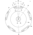
- FIG. 2 is a sectional view showing the rotor 1.
- the rotor 1 has a rotating shaft 40, an annular rotor core 10 surrounding the rotating shaft 40 from the outside in the radial direction, and a resin portion 30 provided therebetween.
- the rotating shaft 40 is a shaft whose central axis is the axis line Ax.
- the rotating shaft 40 is made of metal such as iron, nickel (Ni), or chromium (Cr).
- the resin portion 30 supports the rotor core 10 with respect to the rotating shaft 40 and is made of a non-magnetic material, more specifically a thermoplastic resin such as PBT.
- the resin portion 30 is formed by molding the rotor core 10 and the rotating shaft 40 with resin.
- a rib or a hollow portion may be provided in the resin portion 30 .
- the rotating shaft 40 may be fitted into a shaft hole formed in the rotor core 10 instead of providing the resin portion 30 .
- the rotor core 10 is made by laminating magnetic lamination elements in the axial direction and fixing them by caulking or the like.
- the laminated elements are iron-based core materials, for example electrical steel sheets.
- the thickness of the laminate element is, for example, 0.2-0.5 mm.
- Both the outer circumference 10a and the inner circumference 10b of the rotor core 10 extend in the circumferential direction around the axis Ax.
- a plurality of magnet insertion holes 11 are formed along the outer circumference 10 a of the rotor core 10 .
- the magnet insertion holes 11 are arranged at regular intervals in the circumferential direction.
- the magnet insertion hole 11 extends from one axial end to the other axial end of the rotor core 10 .
- the magnet insertion hole 11 extends linearly in a direction orthogonal to a straight line passing through the center in the circumferential direction and the axis Ax (that is, a pole center line C1 to be described later).
- the number of magnet insertion holes 11 is five here.
- a permanent magnet 20 is arranged in each magnet insertion hole 11 .
- the permanent magnet 20 is flat, has a width in the circumferential direction, and has a thickness in the radial direction. Also, the permanent magnet 20 is magnetized in the thickness direction.
- the permanent magnet 20 is composed of, for example, a rare earth magnet whose main component is neodymium (Nd) or samarium (Sm). Alternatively, a ferrite magnet containing iron as a main component may be used.
- the permanent magnet 20 forms a magnet pole P1.
- the permanent magnets 20 have magnetic pole surfaces of the same polarity (for example, N pole) directed toward the outer circumference 10 a of the rotor core 10 . Therefore, between the permanent magnets 20 adjacent to each other in the rotor core 10, a virtual magnetic pole P2 having a polarity opposite to that of the permanent magnets 20 (for example, S pole) is formed.
- the rotor 1 alternately has five magnet magnetic poles P1 and five virtual magnetic poles P2 in the circumferential direction. Therefore, the rotor 1 has ten poles. Such a rotor structure is called a consequent pole type.
- the number of poles of the rotor 1 is not limited to 10, and may be an even number.
- the number of magnet poles P1 is expressed by N/2
- the number of virtual magnetic poles P2 is also expressed by N/2.
- the magnet pole P1 is also referred to as the first magnetic pole and the virtual magnetic pole P2 is also referred to as the second magnetic pole.
- one permanent magnet 20 is arranged in each magnet insertion hole 11, and the one permanent magnet 20 constitutes the magnet magnetic pole P1.
- two or more permanent magnets may be arranged in each magnet insertion hole 11, and the two or more permanent magnets may constitute the magnet magnetic pole P1 (see FIGS. 10 and 11).
- the permanent magnet 20 does not necessarily have to be flat.
- the center of the magnet magnetic pole P1 in the circumferential direction is the pole center of the magnet magnetic pole P1.
- a straight line passing through the pole center of the magnet magnetic pole P1 and the axis Ax is referred to as a pole center line C1.
- the center of the virtual magnetic pole P2 in the circumferential direction is the pole center of the virtual magnetic pole P2.
- a straight line passing through the pole center of the virtual magnetic pole P2 and the axis Ax is referred to as a pole center line C2.
- the outer circumference 10a of the rotor core 10 has a shape in which the outer diameter is the largest at the pole center of the magnetic poles P1 and P2 and the outer diameter is the smallest at the interpolar portion between the magnetic poles P1 and P2, that is, a flower-shaped shape.
- the shape of the outer periphery 10a of the rotor core 10 is not limited to the flower-round shape, and may be, for example, a circular shape.
- the magnetic flux passing through the virtual magnetic pole P2 easily flows to the rotating shaft 40.
- the resin portion 30 arranged between the rotor core 10 and the rotating shaft 40 has the effect of suppressing magnetic flux leakage to the rotating shaft 40 .
- a flux barrier 12 which is a gap, is formed at both ends of the magnet insertion hole 11 in the circumferential direction.
- a thin portion is formed between the outer periphery 10 a of the rotor core 10 and the flux barrier 12 .
- the thickness of the thin portion in the radial direction is desirably equal to the thickness of the laminated elements of the rotor core 10 in order to suppress leakage flux between adjacent magnetic poles.
- the virtual magnetic poles P2 described above are formed between the flux barriers 12 of the adjacent magnet insertion holes 11 . That is, the flux barrier 12 defines both circumferential ends of the virtual magnetic pole P2. Therefore, the above-described pole center line C2 of the virtual magnetic pole P2 is a straight line that passes through the circumferential intermediate position of the two flux barriers 12 on both sides of the virtual magnetic pole P2 and the axis Ax.
- FIG. 3 is a cross-sectional view showing the rotor 1 in an enlarged manner. 3 and FIGS. 4 to 8 and 10 to 13 described later, the hatching of the rotor core 10 and the resin portion 30 is omitted.
- the permanent magnet 20 has a magnetic pole face 20a on the outer circumference 10a side, a magnetic pole face 20b on the inner circumference 10b side, and end faces 20c on both sides in the circumferential direction. Both of the magnetic pole faces 20a and 20b extend in a direction orthogonal to the pole centerline C1.
- the magnet insertion hole 11 has an outer edge 11a on the side of the outer periphery 10a and an inner edge 11b on the side of the inner periphery 10b. Both the outer edge 11a and the inner edge 11b extend in a direction perpendicular to the pole centerline C1. Stepped portions 11 c are formed at both ends of the inner edge 11 b of the magnet insertion hole 11 .
- the outer edge 11 a of the magnet insertion hole 11 faces the magnetic pole face 20 a of the permanent magnet 20
- the inner edge 11 b of the magnet insertion hole 11 faces the magnetic pole face 20 b of the permanent magnet 20
- the two stepped portions 11 c of the magnet insertion hole 11 face both end faces 20 c of the permanent magnet 20 .
- the flux barrier 12 includes an outer edge 12a extending along the outer circumference 10a of the rotor core 10, a side edge 12b that is an edge on the side of the virtual magnetic pole P2, and extending between the side edge 12b and the stepped portion 11c. and a proximal edge 12c present.
- a slit 13 as a non-magnetic portion is formed between the magnet insertion hole 11 and the outer circumference 10a of the rotor core 10 in the radial direction.
- two slits 13 are formed on both sides of the pole centerline C1.
- the slit 13 extends in the circumferential direction.
- the slit 13 is desirably formed continuously with the flux barrier 12 on the pole center line C1 side of the flux barrier 12 .
- An example in which the slit 13 is formed apart from the flux barrier 12 will be described with reference to FIGS.
- a corner portion R1 is defined as a corner portion between the magnetic pole face 20a and the end face 20c of the permanent magnet 20 on one side (the left side in FIG. 3) of the pole center line C1 of each magnet magnetic pole P1.
- a corner portion R2 is defined as a corner portion between the magnetic pole surface 20a and the end surface 20c of the permanent magnet 20 on the other side (the right side in FIG. 3) of the pole center line C1.
- the corner R1 corresponds to the corner facing the outer circumference 10a of the rotor core 10 and furthest from the pole center line C1 on one side of the pole center line C1.
- the corner R2 corresponds to a corner of the permanent magnet 20 facing the outer circumference 10a of the rotor core 10 and furthest from the pole center line C1 on the other side of the pole center line C1.
- Both the corners R1 and R2 of the permanent magnet 20 are positioned within the space surrounded by the outer edge 12a, the side edge 12b and the base edge 12c of the flux barrier 12.
- the corner R1 is also called the first corner
- the corner R2 is also called the second corner.
- FIG. 4 is a diagram for explaining the arrangement of the magnet magnetic poles P1 and the virtual magnetic poles P2 of the rotor 1.
- FIG. A straight line passing through the corner R1 of the permanent magnet 20 and the axis Ax is defined as a straight line L1.
- a straight line passing through the corner R2 of the permanent magnet 20 and the axis Ax is defined as a straight line L2.
- the angle between the straight line L1 and the straight line L2 be the angle ⁇ m.
- the angle .theta.m represents the range occupied by the permanent magnet 20 in the circumferential direction.
- the angle ⁇ m satisfies ⁇ m ⁇ 360/N.
- N the number of poles of the rotor 1
- the angle ⁇ m should be 36 [degrees] or more.
- the angle ⁇ m is, for example, 40 degrees.
- the range occupied by the permanent magnet 20 is equal to or greater than the angle obtained by equally dividing 360 [degrees] by the number of poles N (that is, 360/N [degrees]).
- a point R3 is the point closest to the outer circumference 10a of the side edge 12b of one of the two flux barriers 12 that are circumferentially adjacent to each other with the virtual magnetic pole P2 interposed therebetween.
- the point closest to the outer circumference 10a of the side edge 12b of the other flux barrier 12 is defined as a point R4.
- a straight line passing through the point R3 and the axis Ax is assumed to be a straight line L3, and a straight line passing through the point R4 and the axis Ax is assumed to be a straight line L4.
- the angle formed by the straight lines L3 and L4 is assumed to be an angle ⁇ v.
- the angle ⁇ v represents the range occupied by the virtual magnetic pole P2 in the circumferential direction.
- the angle ⁇ v satisfies ⁇ v ⁇ 360/N and also satisfies ⁇ v ⁇ m.
- the angle ⁇ v is, for example, 30 degrees. That is, the angle ⁇ v occupied by the virtual magnetic pole P2 is smaller than the angle ⁇ m occupied by the permanent magnet 20 .
- the one flux barrier 12 is also called a first gap, and the other flux barrier 12 is also called a second gap.
- Point R3 is also referred to as the third point, and point R4 is also referred to as the fourth point.
- FIG. 5(A) is an enlarged view of the magnetic pole P1 of the magnet.
- FIG. 5B is an enlarged view of a region including the end of the permanent magnet 20.
- slits 13 are formed on both sides of the pole center line C1 of the magnet magnetic pole P1. The area between two slits 13 is also called inter-slit area.
- the slit 13 includes an outer edge 13a extending along the outer periphery 10a of the rotor core 10, an inner edge 13b facing the outer edge 13a in the radial direction, and a tip edge formed on the pole center line C1 side. 13c.
- the outer edge 13a of the slit 13 here extends on the extension line of the outer edge 12a of the flux barrier 12 .
- a curved portion 13 d is formed between the inner edge 13 b of the slit 13 and the outer edge 11 a of the magnet insertion hole 11 .
- the slit 13 has a length A in the circumferential direction and a width B in the radial direction, and the relationship between the length A and the width B is A>B.
- the length A is the distance from the tip edge 13c of the slit 13 to the curved portion 13d.
- the width B is the distance between the outer edge 13a and the inner edge 13b.
- a core region 14 is formed between the inner edge 13 b of the slit 13 and the outer edge 11 a of the magnet insertion hole 11 .
- the core region 14 constitutes part of the magnetic path from the permanent magnet 20 to the inter-slit region.
- the core region 14 has a width W in the radial direction. The width W is the radial distance between the inner edge 13 b of the slit 13 and the outer edge 11 a of the magnet insertion hole 11 .
- the inner edge 13b of the slit 13 extends along the outer periphery 10a of the rotor core 10, the distance from the outer edge 11a of the magnet insertion hole 11 increases as it approaches the pole center line C1. Therefore, the radial width W of the core region 14 increases as it approaches the pole centerline C1.
- the point closest to the outer circumference 10a at the leading end edge 13c of one of the two slits 13 of the magnet magnetic pole P1 is defined as a point R5.
- the point closest to the outer periphery 10a at the tip edge 13c of the other slit 13 is defined as a point R6.
- a straight line passing through the point R5 and the axis Ax is assumed to be a straight line L5, and a straight line passing through the point R5 and the axis Ax is assumed to be a straight line L6.
- the angle formed by these straight lines L5 and L6 is defined as angle ⁇ s.
- the angle .theta.s represents the range occupied by the inter-slit region in the circumferential direction.
- the angle ⁇ s is smaller than the above angle ⁇ m, and therefore satisfies ⁇ s ⁇ m and also satisfies ⁇ s ⁇ 360/N [degrees].
- the angle ⁇ s is, for example, 25 degrees.
- the one slit 13 is also called a first non-magnetic portion, and the other slit 13 is also called a second non-magnetic portion.
- the point R5 is also called the first point and the point R6 is also called the second point.
- Embodiment 1 Next, the operation of Embodiment 1 will be described. As the area of the magnetic pole surface 20a of the permanent magnet 20 increases, the amount of magnetic flux emitted from the magnetic pole surface 20a increases and the magnetic force increases. However, if the axial length of the permanent magnet 20 is lengthened, the axial length of the electric motor 2 is lengthened, leading to an increase in the size of the electric motor 2 or an increase in manufacturing cost. Therefore, it is desirable to increase the area of the magnetic pole face 20a of the permanent magnet 20 per unit length in the axial direction.
- the angle ⁇ m occupied by the permanent magnet 20 is 360/N [degree] or more. Therefore, the width of the pole face 20a of the permanent magnet 20 can be widened, and the area of the pole face 20a of the permanent magnet 20 per unit length in the axial direction can be increased. Thereby, the amount of magnetic flux emitted from the magnetic pole face 20a can be increased, and the magnetic force of the permanent magnet 20 can be increased.
- the rotor 1 of Embodiment 1 is of the consequent pole type, and no permanent magnets are arranged in the virtual magnetic poles P2. Therefore, it is possible to set the angle ⁇ m occupied by the permanent magnet 20 to 360/N [degree] or more.
- the output of the electric motor 2 can be increased while suppressing an increase in the manufacturing cost of the electric motor 2.
- the axial length of the electric motor 2 required to obtain the same magnetic force can be shortened.
- the core material of rotor core 10 and stator core 50 can be reduced, and the total length of coil 55 can be shortened. That is, the manufacturing cost of the electric motor 2 can be reduced, and efficiency can be improved.
- the angle ⁇ m of the permanent magnets 20 exceeds 720/N [degrees], a space for forming the virtual magnetic poles P2 cannot be secured between the adjacent permanent magnets 20 . Therefore, the angle ⁇ m is set so as to satisfy 360/N [degrees] ⁇ m ⁇ 720/N [degrees].
- the angle ⁇ m occupied by the permanent magnet 20 becomes larger than the angle ⁇ v occupied by the virtual magnetic pole P2 (that is, ⁇ m> ⁇ v). Therefore, if the magnet magnetic pole P1 is assumed to be the north pole and the virtual magnetic pole P2 is assumed to be the south pole, the width of the north pole on the surface of the rotor 1 is wider than the width of the south pole.
- the rotor 1 of Embodiment 1 has two slits 13 that limit the magnetic path on both sides of the pole center line C1 of the magnet magnetic pole P1.
- the slit 13 is long in the circumferential direction. This is a shape suitable for controlling the flow of magnetic flux.
- FIG. 6 is a schematic diagram for explaining the flow of magnetic flux in the magnet magnetic pole P1 and the virtual magnetic pole P2 of the rotor 1.
- FIG. Here, the magnetic pole surface 20a of the permanent magnet 20 of the magnet magnetic pole P1 is assumed to be the N pole.
- the magnetic flux emitted from the magnetic pole faces 20a of the permanent magnets 20 is directed toward the outer circumference 10a of the rotor core 10.
- the slit 13 formed on the side of the outer periphery 10a of the magnet insertion hole 11 prevents passage of magnetic flux because the inside thereof is air or other non-magnetic material.
- the magnetic flux emitted from the magnetic pole surface 20a of the permanent magnet 20 passes through the area between the two slits 13, that is, the inter-slit area, toward the stator 5.
- the angle occupied by the inter-slit region is the above angle ⁇ s.
- This angle ⁇ s is smaller than the angle ⁇ m occupied by the permanent magnets 20 . That is, the slit 13 has a role of restricting the flow of the magnetic flux emitted from the magnetic pole surface 20a of the permanent magnet 20. As shown in FIG.
- the widths of the north and south poles on the surface of the rotor 1 can be brought closer to each other. This can reduce vibration and noise caused by the difference in width between the N pole and the S pole.
- the amount of core of the virtual magnetic pole P2 is equal to the amount of core of the magnetic pole P1. , and therefore the magnetic attraction force between the rotor 1 and the stator 5 becomes large at the virtual magnetic pole P2.
- the amount of core is the amount of core material such as an electromagnetic steel sheet.
- the core amount of the magnet magnetic pole P1 and the core amount of the virtual magnetic pole P2 can be brought closer, and vibration caused by the difference in magnetic attraction force can be reduced.
- the number of slits 13 may be one because even one slit 13 can limit the magnetic path.
- the core region 14 shown in FIG. 5(B) constitutes a part of the magnetic path from the magnetic pole face 20a of the permanent magnet 20 to the region between the slits.
- the core region 14 shown in FIG. 5(B) constitutes a part of the magnetic path from the magnetic pole face 20a of the permanent magnet 20 to the region between the slits.
- the radial width W of the core region 14 becomes wider as it approaches the pole center line C1, it is possible to suppress local concentration of magnetic flux and magnetic saturation caused thereby. Thereby, the magnetic flux of the permanent magnet 20 can be effectively used.
- FIG. 7 is a cross-sectional view showing another configuration example of the rotor 1.
- FIG. 8 is an enlarged view of the magnetic pole P1 of the rotor 1 of FIG.
- slits 15 are formed on both sides of the pole center line C1 of each magnet magnetic pole P1, and each slit 15 is formed away from the flux barrier 12.
- the slit 15 includes an outer edge 15a on the outer periphery 10a side of the rotor core 10, an inner edge 15b on the magnet insertion hole 11 side, a tip edge 15c on the pole center line C1 side, and the flux barrier 12 side proximal edge 15d.
- the length A in the circumferential direction and the width B in the radial direction of the slit 15 have a relation of A>B.
- Each slit 15 functions to restrict the magnetic path of the magnet magnetic pole P1, and an inter-slit region is formed between two slits 15.
- the angle occupied by the inter-slit region is the above angle ⁇ s.
- a bridge portion 16 is formed between the slit 15 and the flux barrier 12 .
- the magnetic flux emitted from the magnetic pole surface 20a of the permanent magnet 20 passes through not only the inter-slit region but also the bridge portion 16. That is, the function of restricting the magnetic path of the magnet magnetic pole P1 is reduced by the magnetic flux flowing through the bridge portion 16 .
- the slits 13 when the slits 13 are formed continuously in the flux barrier 12 as shown in FIGS. , the slit 13 can effectively exhibit the function of limiting the magnetic path of the magnet pole P1.
- the magnetic pole P1 of the magnet is the N pole
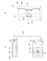
- FIG. 9 is a longitudinal sectional view showing a molded electric motor to which the electric motor 2 of Embodiment 1 is applied.
- the stator 5 is covered with a molded resin portion 60 to form a molded stator 6 .
- the mold resin portion 60 is made of a thermosetting resin such as BMC (bulk molding compound), for example.
- the mold resin portion 60 has an opening 61 on the left side in FIG. 9 and a bearing support portion 62 on the opposite side.
- the rotor 1 is inserted into the inner hollow portion of the stator 5 through the opening 61 .
- a metal bracket 44 is attached to the opening 61 of the mold resin portion 60 .
- This bracket 44 holds the bearing 41 .
- a cap 43 is attached to the outside of the bracket 44 to prevent water or the like from entering the bearing 41 .
- the bearing 42 is held by the bearing support portion 62 .
- a rotary shaft 40 is supported by the bearings 41 and 42 .
- the rotating shaft 40 protrudes from the stator 5 to the left in FIG. 9, and an impeller of a blower, for example, is attached to the tip 40a thereof. Therefore, the protruding side (left side in FIG. 9) of the rotating shaft 40 is called “load side”, and the opposite side (right side in FIG. 9) is called “counter-load side”.
- a circuit board 70 is arranged on the anti-load side of the stator 5 .
- a magnetic sensor 71 and a drive circuit 72 for driving the electric motor 2 are mounted on the circuit board 70, and lead wires 73 are wired.
- the lead wires 73 include power lead wires for supplying power to the coils 55 of the stator 5 and sensor lead wires for transmitting signals from the magnetic sensor 71 to the outside.
- a lead wire lead-out component 74 for drawing out the lead wire 73 to the outside is attached to the outer peripheral portion of the mold resin portion 60 .
- the resin portion 30 of the rotor 1 is provided between the rotor core 10 and the rotary shaft 40 and also covers both axial end surfaces of the rotor core 10 .
- a sensor magnet 17 is arranged on the anti-load side of the rotor core 10 and held by a resin portion 30 .
- the sensor magnet 46 is an annular magnet and has the same magnetic poles as the rotor 1 .
- a magnetic sensor 71 mounted on the circuit board 70 is composed of, for example, a Hall IC, and detects the magnetic flux of the sensor magnet 46 .
- the drive circuit 72 detects the rotational position of the rotor 1 based on the detection signal from the magnetic sensor 71 and controls the current flowing through the coil 55 .
- sensorless control may be performed to estimate the rotational position of the rotor 1 from the current flowing through the coil 55 or the like.
- stator 5 is covered with the molded resin portion 60 here, the stator 5 may be fitted inside a metal shell.
- the rotor 1 of the first embodiment has the rotor core 10 and the permanent magnets 20.
- the permanent magnets 20 form N/2 (N is an even number) magnetic poles P1.
- N/2 virtual magnetic poles P2 are formed.
- the permanent magnet 20 has a corner portion R1 facing the outer circumference 10a of the rotor core 10 and furthest to one side from the pole center line C1, and a corner R1 facing the outer circumference 10a of the rotor core 10 and furthest to the other side from the pole center line C1. and a corner R2.
- An angle ⁇ m between a straight line L1 passing through the corner R1 and the axis Ax and a straight line L2 passing through the corner R2 and the axis Ax satisfies ⁇ m ⁇ 360/N degrees.
- the area of the magnetic pole faces 20a of the permanent magnets 20 per unit length in the axial direction can be increased, and the magnetic force of the permanent magnets 20 can be increased. That is, it is possible to increase the output and improve the efficiency while suppressing an increase in the manufacturing cost of the electric motor 2 .
- slits 13 are formed as non-magnetic portions extending in the circumferential direction between the permanent magnets 20 and the outer periphery 10a of the rotor core 10, the magnetic paths of the magnet magnetic poles P1 can be restricted. As a result, the difference in width between the N pole and the S pole on the surface of the rotor 1 can be suppressed, and vibration and noise can be reduced.
- the slit 13 is formed continuously with the magnet insertion hole 11, compared with the case where the slit 13 is formed away from the magnet insertion hole 11, the effect of limiting the magnetic path of the magnetic pole P1 of the magnet is reduced. can be enhanced.
- the core region 14 is formed between the slit 13 and the magnet insertion hole 11, and the width W of the core region 14 increases as the width W of the core region 14 approaches the pole center line C1, the distance from the magnetic pole surface 20a of the permanent magnet 20 to the region between the slits increases. can suppress the occurrence of magnetic saturation in the magnetic path of
- the point closest to the outer periphery 10a of the leading edge 13c of one slit 13 is defined as a point R5
- the point closest to the outer periphery 10a of the leading edge 13c of the other slit 13 is defined as R5.
- an angle ⁇ s formed by a straight line L5 passing through the point R5 and the axis Ax and a straight line L6 passing through the point R6 and the axis Ax satisfies ⁇ s ⁇ 360/N [degrees]. Therefore, the widths of the N poles and S poles on the surface of the rotor 1 can be brought closer to each other, and vibration and noise can be reduced.
- a point R3 is the point closest to the outer circumference 10a of the side edge 12b of one of the flux barriers 12 on both sides in the circumferential direction of the virtual magnetic pole P2.
- a point near the outer circumference 10a is a point R4
- an angle ⁇ v between a straight line L4 passing through the point R3 and the axis Ax and a straight line L4 passing through the point R4 and the axis Ax satisfies ⁇ v ⁇ s. Therefore, the widths of the north and south poles on the surface of the rotor 1 can be brought closer to each other, and variations in the magnetic attraction force between the rotor 1 and the stator 5 can be reduced, thereby reducing vibration and noise.
- FIG. 10 is a cross-sectional view showing a rotor 1A of Modification 1. As shown in FIG. In the rotor 1 of Embodiment 1 described above, one permanent magnet 20 is inserted into each magnet insertion hole 11 . On the other hand, in the rotor 1 ⁇ /b>A of Modification 1, two permanent magnets 21 and 22 are inserted into each magnet insertion hole 11 .
- the rotor core 10 of the rotor 1A has N/2 magnet insertion holes 11 formed therein.
- the magnet insertion hole 11 has a V shape in which the center in the circumferential direction protrudes toward the inner circumference 10 b of the rotor core 10 .
- Permanent magnets 21 are arranged on one side of the magnet insertion hole 11 and permanent magnets 22 are arranged on the other side of the magnet insertion hole 11 across the center in the circumferential direction.
- the permanent magnet 21 is also called the first permanent magnet and the permanent magnet 22 is also called the second permanent magnet.
- the permanent magnet 21 has a magnetic pole face 21a on the outer circumference 10a side, a magnetic pole face 21b on the inner circumference 10b side, and end faces 21c on both ends in the circumferential direction.
- the permanent magnet 22 has a magnetic pole face 22a on the side of the outer circumference 10a, a magnetic pole face 22b on the side of the inner circumference 10b, and end faces 22c on both ends in the circumferential direction.
- the magnet insertion hole 11 has an outer edge 11a on the side of the outer circumference 10a and an inner edge 11b on the side of the inner circumference 10b. There is Stepped portions 11c are formed on both circumferential sides of the inner edge 11b.
- the outer edge 11a of the magnet insertion hole 11 faces the magnetic pole faces 21a and 22a of the permanent magnets 21 and 22.
- An inner edge 11b of the magnet insertion hole 11 faces the magnetic pole faces 21b and 22b of the permanent magnets 21 and 22, respectively.
- the stepped portion 11c of the magnet insertion hole 11 faces the end faces 21c, 22c of the permanent magnets 21, 22 on the side away from the pole center line C1.
- the permanent magnets 21 and 22 arranged in each magnet insertion hole 11 form a magnet magnetic pole P1 as a first magnetic pole.
- a virtual magnetic pole P2 as a second magnetic pole is formed between the adjacent magnet magnetic poles P1.
- the pole center line C1 is a straight line that passes through the circumferential center of the magnet magnetic pole P1, that is, the circumferential center of the magnet insertion hole 11, and the axis Ax.
- the pole center line C2 is a straight line passing through the center of the virtual magnetic pole P2 in the circumferential direction and the axis Ax.
- corner R1 the corner between the magnetic pole face 21a and the end face 21c on the side away from the pole center line C1 is defined as corner R1.
- corner R2 the corner between the magnetic pole face 22a and the end face 22c on the side away from the pole center line C1 is defined as corner R2.
- Both the corners R1 and R2 of the permanent magnets 21 and 22 are located inside the flux barrier 12 .
- the corner R1 corresponds to the corner facing the outer circumference 10a of the rotor core 10 and furthest from the pole center line C1 on one side (the left side in FIG. 10) of the pole center line C1.
- the corner R2 corresponds to the corner facing the outer circumference 10a of the rotor core 10 and furthest from the pole center line C1 on the other side (the right side in FIG. 10) of the pole center line C1.
- An angle ⁇ m is defined by a straight line L1 passing through the corner R1 of the permanent magnet 20 and the axis Ax and a straight line L2 passing through the corner R2 and the axis Ax.
- the angle .theta.m represents the range occupied by the permanent magnets 21 and 22 in the circumferential direction.
- the angle ⁇ m satisfies ⁇ m ⁇ 360/N. Since the angle ⁇ m is 360/N [degrees] or more, the areas of the magnetic pole faces 21a, 22a of the permanent magnets 21, 22 per unit length in the axial direction can be increased.
- the formation of the slit 13 on the side of the outer circumference 10a of the magnet insertion hole 11 is the same as in the first embodiment. Also, the angle ⁇ s of the inter-slit region and the angle ⁇ v of the virtual magnetic pole P2 are as described in the first embodiment.
- the rotor 1A of Modification 1 is configured in the same manner as the rotor 1 of Embodiment 1.
- two permanent magnets 21 and 22 may be arranged in the straight magnet insertion hole 11 .
- the angle ⁇ m occupied by the permanent magnets 21 and 22 is set to 360/N degrees or more.
- the area of the magnetic pole faces 21a, 22a of the permanent magnets 21, 22 per unit length in the axial direction can be increased, and the magnetic force can be increased.
- FIG. 11 is a cross-sectional view showing a rotor 1B of Modification 2. As shown in FIG. In the rotor 1 of Embodiment 1 described above, one permanent magnet 20 is inserted into each magnet insertion hole 11 . On the other hand, in the rotor 1 ⁇ /b>B of Modification 2, three permanent magnets 23 , 24 , 25 are inserted into each magnet insertion hole 11 .
- the rotor core 10 of the rotor 1B has N/2 magnet insertion holes 11 formed therein.
- Magnet insertion hole 11 has a central portion located in the center in the circumferential direction, and two inclined portions extending from both ends of the central portion toward outer periphery 10 a of rotor core 10 .
- the two sloped portions are sloped such that the distance between the two sloped portions widens with increasing distance from the central portion. In other words, the magnet insertion hole 11 has a bathtub shape.
- a permanent magnet 23 is arranged in the central portion of the magnet insertion hole 11, and permanent magnets 24 and 25 are arranged in the two inclined portions. Both the permanent magnets 24 and 25 are inclined so that the distance between the two permanent magnets 24 and 25 widens as the distance from the permanent magnet 23 increases. In other words, the permanent magnets 23, 24, 25 are arranged like a bathtub.
- the permanent magnet 23 is also referred to as a first permanent magnet, the permanent magnet 24 as a second permanent magnet, and the permanent magnet 25 as a third permanent magnet.
- the permanent magnet 23 has a magnetic pole face 23a on the outer circumference 10a side, a magnetic pole face 23b on the inner circumference 10b side, and end faces 23c on both ends in the circumferential direction.
- the permanent magnet 24 has a magnetic pole face 24a on the pole center side, a magnetic pole face 24b on the opposite side, and end faces 24c on both ends in the circumferential direction.
- the permanent magnet 25 has a magnetic pole face 25a on the pole center side, a magnetic pole face 25b on the opposite side, and end faces 25c on both ends in the circumferential direction.
- the magnet insertion hole 11 has an outer edge 11a on the side of the outer periphery 10a and an inner edge 11b on the side of the inner periphery 10b.
- the outer edge 11a of the magnet insertion hole 11 faces the magnetic pole faces 23a, 24a, 25b of the permanent magnets 23, 24, 25.
- the inner edge 11b of the magnet insertion hole 11 faces the magnetic pole faces 23b, 24b, 25b of the permanent magnets 23, 24, 25.
- a stepped portion for positioning the permanent magnets 23 , 24 , 25 may be provided in the magnet insertion hole 11 .
- the permanent magnets 23, 24, and 25 arranged in each magnet insertion hole 11 form a magnet magnetic pole P1 as a first magnetic pole.
- a virtual magnetic pole P2 as a second magnetic pole is formed between the adjacent magnet magnetic poles P1.
- the pole center line C1 is a straight line that passes through the circumferential center of the magnet magnetic pole P1, that is, the circumferential center of the magnet insertion hole 11, and the axis Ax.
- the pole center line C2 is a straight line passing through the center of the virtual magnetic pole P2 in the circumferential direction and the axis Ax.
- corner R1 the corner between the magnetic pole face 24a and the end face 24c on the side away from the pole center line C1 is defined as corner R1.
- corner R2 the corner between the magnetic pole face 25a and the end face 25c on the side away from the pole center line C1 is defined as corner R2.
- Both the corners R1 and R2 of the permanent magnets 24 and 25 are located within the flux barrier 12 .
- the corner R1 corresponds to the corner facing the outer circumference 10a of the rotor core 10 and furthest from the pole center line C1 on one side of the pole center line C1.
- the corner R2 corresponds to the corner facing the outer circumference 10a of the rotor core 10 and furthest from the pole centerline C1 on the other side of the pole centerline C1.
- An angle ⁇ m is defined by a straight line L1 passing through the corner R1 of the permanent magnet 20 and the axis Ax and a straight line L2 passing through the corner R2 and the axis Ax.
- the angle .theta.m represents the range occupied by the permanent magnets 23, 24, 25 in the circumferential direction.
- the angle ⁇ m satisfies ⁇ m ⁇ 360/N. Since the angle ⁇ m is 360/N [degree] or more, the areas of the magnetic pole faces 23a, 24a, 25a of the permanent magnets 23, 24, 25 per unit length in the axial direction can be increased.
- the formation of the slit 13 on the side of the outer circumference 10a of the magnet insertion hole 11 is the same as in the first embodiment. Also, the angle ⁇ s of the inter-slit region and the angle ⁇ v of the virtual magnetic pole P2 are as described in the first embodiment.
- the rotor 1B of Modification 2 is configured in the same manner as the rotor 1 of Embodiment 1.
- the three permanent magnets 23, 24, and 25 may be arranged in the linear magnet insertion hole 11.
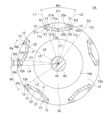
- FIG. 12 is a sectional view showing the rotor 1C of the second embodiment.
- the circumferential width of the virtual magnetic pole P2 differs between the radially outer side and the radially inner side.
- the rotor core 10 of the rotor 1C has N/2 magnet insertion holes 11 formed therein.
- the shape of the magnet insertion hole 11 is as described in the first embodiment.
- One permanent magnet 20 is arranged in each magnet insertion hole 11 .
- Flux barriers 12 are formed as air gaps at both circumferential ends of each magnet insertion hole 11 .
- FIG. 13 is an enlarged view showing a part of the rotor 1C. As shown in FIG. 13, flux barriers 12 are formed on both sides of the virtual magnetic pole P2. The flux barrier 12 is also a portion that defines both circumferential ends of the virtual magnetic pole P2.
- the flux barrier 12 includes an outer edge 12a extending along the outer circumference 10a of the rotor core 10, a side edge 12b that is an edge on the side of the virtual magnetic pole P2, and extending between the side edge 12b and the stepped portion 11c. and a proximal edge 12c present.
- a point R3 is the point closest to the outer circumference 10a of the side edge 12b of one of the two flux barriers 12 adjacent to each other with the virtual magnetic pole P2 interposed therebetween.
- the point closest to the outer circumference 10a of the side edge 12b of the other flux barrier 12 is defined as a point R4.
- the point closest to the inner circumference 10b of the side edge 12b of the one flux barrier 12 is defined as a point R7.
- the point closest to the inner circumference 10b of the side edge 12b of the other flux barrier 12 is defined as a point R8.
- distance E1 be the distance in the circumferential direction between point R3 and point R4.
- the distance in the circumferential direction between points R7 and R8 is defined as distance E2.
- the distance E1 and the distance E2 have a relationship of E1>E2.
- the distance E1 corresponds to the radially outer width of the virtual magnetic pole P2
- the distance E2 corresponds to the radially inner width of the virtual magnetic pole P2. Therefore, the relationship of E1>E2 means that the width of the virtual magnetic pole P2 in the circumferential direction is wider at the radially outer side than at the radially inner side.
- a straight line passing through the point R3 and the axis Ax is defined as a straight line L3
- a straight line passing through the point R4 and the axis Ax is defined as a straight line L4.
- the angle formed by the straight lines L3 and L4 is assumed to be an angle ⁇ v1.
- This angle ⁇ v1 is an angle corresponding to the above distance E1.
- a straight line passing through the point R7 and the axis Ax is called a straight line L7
- a straight line passing through the point R8 and the axis Ax is called a straight line L8.
- the angle formed by the straight line L7 and the straight line L8 is assumed to be an angle ⁇ v2.
- This angle ⁇ v2 is an angle corresponding to the above distance E2.
- Both the angle ⁇ v1 and the angle ⁇ v2 are less than 360/N [degree]. Further, the angle ⁇ v1 and the angle ⁇ v2 have a relationship of ⁇ v1> ⁇ v2. This corresponds to the above relationship of E1>E2.
- the distance E1 which is the radially outer width of the virtual magnetic pole P2 is greater than the distance E2, which is the radially inner width.
- the slit 13 between the magnet insertion hole 11 and the outer circumference 10a of the rotor core 10 and the inter-slit region are as described in the first embodiment. It is desirable that the angle ⁇ s of the inter-slit region be equal to or greater than the angle ⁇ v1, that is, ⁇ v1 ⁇ s. As a result, the difference in width between the N pole and the S pole on the surface of the rotor 1C can be reduced, and vibration caused by the difference in magnetic attraction force can be reduced.
- the rotor 1C of Embodiment 2 is configured in the same manner as the rotor 1 of Embodiment 1 except for the points described above.
- the circumferential distance between the flux barriers 12 on both sides of the virtual magnetic pole P2 is wider on the radial outer side than on the radial inner side. Therefore, it is possible to increase the magnetic force by increasing the area of the magnetic pole faces 20a of the permanent magnets 20 while reducing the difference in width between the N pole and the S pole on the surface of the rotor 1C. It is possible to increase the output and improve efficiency while suppressing an increase in the manufacturing cost of the electric motor 2 .
- FIG. 14(A) is a diagram showing the configuration of an air conditioner 500 to which the electric motor 2 of Embodiment 1 is applied.
- An air conditioner 500 includes an outdoor unit 501 and an indoor unit 502 .
- the outdoor unit 501 and the indoor unit 502 are connected by a refrigerant pipe 503 .
- the outdoor unit 501 includes an outdoor fan 510 such as a propeller fan
- the indoor unit 502 includes an indoor fan 520 such as a cross-flow fan.
- the outdoor fan 510 has an impeller 511 and an electric motor 2A for driving the same.
- the indoor fan 520 has an impeller 521 and an electric motor 2B that drives it. Both the electric motors 2A and 2B are configured with the electric motor 2 described in the first embodiment.
- FIG. 14A also shows a compressor 504 that compresses the refrigerant.
- FIG. 14(B) is a cross-sectional view of the outdoor unit 501.
- the electric motor 2A is supported by a frame 509 arranged inside the housing 508 of the outdoor unit 501 .
- An impeller 511 is attached via a hub 512 to the rotary shaft 40 of the electric motor 2A.
- the impeller 511 is rotated by the electric motor 2A to blow air outdoors.
- the heat released when the refrigerant compressed by the compressor 504 is condensed by the condenser (not shown) is released to the outside by the outdoor fan 510.
- the impeller 521 is rotated by the electric motor 2B to blow air into the room.
- the indoor blower 520 blows air into the room from which heat has been removed when the refrigerant evaporates in an evaporator (not shown).
- the electric motors 2A and 2B are configured with the electric motor 2 of Embodiment 1, a higher output can be obtained. Therefore, the operating efficiency of outdoor fan 510 and indoor fan 520 can be improved.
- the electric motors 2A and 2B are not limited to the electric motor 2 of the first embodiment, and may have the electric motors of the second embodiment or each modification. Moreover, although the electric motors of the respective embodiments and modifications are used for both the outdoor fan 510 and the indoor fan 520 here, they may be used for only one of them.
- the electric motor 2 described in each embodiment is not limited to a blower, and may be used as a compressor of an air conditioner. may be used for
Abstract
This rotor has N/2 magnet poles (N an even number) and N/2 virtual poles. The rotor has an annular rotor core centered on an axis, and multiple permanent magnets attached to the rotor core. The N/2 magnet poles are all formed by at least one of multiple permanent magnets and the N/2 virtual poles are all formed by the rotor core. The polar centerline of each magnet pole is defined by the straight line that passes through the axis and the center of the magnet pole in the circumferential direction of the rotor core. At least one permanent magnet forming a magnet pole has a first corner facing the outer circumference of the rotor core and furthest from the polar centerline on one side of the polar centerline, and a second corner facing the outer circumference and furthest from the polar centerline on the other side of the polar centerline. The angle θm formed by the straight line through the first corner and the axis and the straight line through the second corner and the axis satisfies θm ≥ 360[degrees].
Description
本開示は、ロータ、電動機、送風機および空気調和装置に関する。
The present disclosure relates to rotors, electric motors, blowers, and air conditioners.
近年、コンシクエントポール型のロータを有する電動機が開発されている。コンシクエントポール型のロータでは、ロータコアに取り付けられた永久磁石によって磁石磁極が形成され、ロータコアの一部によって仮想磁極が形成される(例えば、特許文献1参照)。
In recent years, motors with consequent-pole rotors have been developed. In a consequent-pole rotor, permanent magnets attached to the rotor core form magnet poles, and part of the rotor core forms virtual poles (see, for example, Patent Document 1).
近年、電動機の高出力化に伴い、永久磁石の磁力の増加が望まれている。永久磁石の磁力を増加させるためには、永久磁石の磁極面の面積を大きくして磁束量を増加させる必要がある。一方、永久磁石の軸方向長さを長くすると、それに応じて電動機の軸方向長さを長くしなければならず、製造コストの上昇を招く。
In recent years, as the output of electric motors has increased, there has been a demand for an increase in the magnetic force of permanent magnets. In order to increase the magnetic force of the permanent magnet, it is necessary to increase the magnetic flux amount by increasing the area of the magnetic pole face of the permanent magnet. On the other hand, if the axial length of the permanent magnet is lengthened, the axial length of the electric motor must be correspondingly lengthened, resulting in an increase in manufacturing cost.
本開示は、上記の課題を解決するためになされたものであり、製造コストの上昇を抑えながら永久磁石の磁力を増加させることを目的とする。
The present disclosure has been made to solve the above problems, and aims to increase the magnetic force of a permanent magnet while suppressing an increase in manufacturing costs.
本開示のロータは、N/2個(Nは偶数)の磁石磁極と、N/2個の仮想磁極とを有する。ロータは、軸線を中心とする環状のロータコアと、ロータコアに取り付けられた複数の永久磁石とを有する。N/2個の磁石磁極はいずれも、複数の永久磁石のうちの少なくとも1つの永久磁石によって形成され、N/2個の仮想磁極はいずれも、ロータコアの一部によって形成される。各磁石磁極の極中心線は、ロータコアの周方向における磁石磁極の中心と軸線とを通る直線で定義される。磁石磁極を形成する少なくとも1つの永久磁石は、ロータコアの外周に対向し且つ極中心線の一方の側で極中心線から最も離れた第1の角部と、外周に対向し且つ極中心線の他方の側で極中心線から最も離れた第2の角部とを有する。第1の角部と軸線とを通る直線と、第2の角部と軸線とを通る直線とのなす角度θmは、θm≧360/N[度]を満足する。
The rotor of the present disclosure has N/2 (N is an even number) magnet magnetic poles and N/2 virtual magnetic poles. The rotor has an annular rotor core centered on the axis and a plurality of permanent magnets attached to the rotor core. All N/2 magnet magnetic poles are formed by at least one permanent magnet of the plurality of permanent magnets, and all N/2 virtual magnetic poles are formed by a portion of the rotor core. The pole centerline of each magnet pole is defined by a straight line passing through the center of the magnet pole and the axis in the circumferential direction of the rotor core. At least one permanent magnet forming the magnet poles has a first corner facing the outer periphery of the rotor core and furthest from the pole center line on one side of the pole center line, and a first corner facing the outer periphery and at the pole center line. and a second corner furthest from the polar centerline on the other side. An angle θm between a straight line passing through the first corner and the axis and a straight line passing through the second corner and the axis satisfies θm≧360/N [degrees].
本開示によれば、角度θmが360/N[度]以上であるため、軸方向の単位長さ当たりの永久磁石の磁極面の面積を大きくすることができる。その結果、製造コストの上昇を抑えながら永久磁石の磁力を増加させることができる。
According to the present disclosure, since the angle θm is 360/N [degree] or more, the area of the magnetic pole face of the permanent magnet per unit length in the axial direction can be increased. As a result, it is possible to increase the magnetic force of the permanent magnet while suppressing an increase in manufacturing cost.
実施の形態1.
<電動機2の構成>
図1は、実施の形態1の電動機2を示す断面図である。電動機2は、回転可能なロータ1と、ロータ1を囲むように設けられた環状のステータ5とを備えたインナロータ型の電動機である。ステータ5とロータ1との間には、例えば0.4~0.7mmのエアギャップGが設けられている。Embodiment 1.
<Configuration ofelectric motor 2>
FIG. 1 is a cross-sectional view showing anelectric motor 2 according to Embodiment 1. FIG. The electric motor 2 is an inner rotor type electric motor that includes a rotatable rotor 1 and an annular stator 5 that surrounds the rotor 1 . An air gap G of 0.4 to 0.7 mm is provided between the stator 5 and the rotor 1, for example.
<電動機2の構成>
図1は、実施の形態1の電動機2を示す断面図である。電動機2は、回転可能なロータ1と、ロータ1を囲むように設けられた環状のステータ5とを備えたインナロータ型の電動機である。ステータ5とロータ1との間には、例えば0.4~0.7mmのエアギャップGが設けられている。
<Configuration of
FIG. 1 is a cross-sectional view showing an
以下では、ロータ1の回転中心となる軸線を軸線Axとし、この軸線Axの方向を「軸方向」と称する。軸線Axを中心とする円周方向を「周方向」と称し、軸線Axを中心とする半径方向を「径方向」と称する。なお、図1は、ロータ1の軸線Axに直交する面における断面図である。
Hereinafter, the axis line that is the center of rotation of the rotor 1 is defined as the axis line Ax, and the direction of this axis line Ax is referred to as the "axial direction". A circumferential direction about the axis Ax is called a “circumferential direction”, and a radial direction about the axis Ax is called a “radial direction”. 1 is a cross-sectional view of the rotor 1 in a plane perpendicular to the axis Ax.
<ステータの構成>
ステータ5は、ステータコア50と、ステータコア50に巻き付けられたコイル55とを有する。ステータコア50は、磁性を有する積層要素を軸方向に積層し、カシメ等により固定したものである。積層要素は、鉄(Fe)を主成分とするコア材料、例えば電磁鋼板である。積層要素の厚さは、例えば0.2mm~0.5mmである。 <Structure of stator>
Thestator 5 has a stator core 50 and a coil 55 wound around the stator core 50 . The stator core 50 is formed by laminating magnetic lamination elements in the axial direction and fixing them by caulking or the like. The lamination element is a core material containing iron (Fe) as a main component, such as an electromagnetic steel sheet. The thickness of the laminate element is, for example, 0.2 mm to 0.5 mm.
ステータ5は、ステータコア50と、ステータコア50に巻き付けられたコイル55とを有する。ステータコア50は、磁性を有する積層要素を軸方向に積層し、カシメ等により固定したものである。積層要素は、鉄(Fe)を主成分とするコア材料、例えば電磁鋼板である。積層要素の厚さは、例えば0.2mm~0.5mmである。 <Structure of stator>
The
ステータコア50は、軸線Axを中心とする環状のヨーク52と、ヨーク52から径方向内側に延在する複数のティース51とを有する。ティース51は、周方向に等間隔に配置されている。ティース51の数は、ここでは12であるが、12に限定されるものではない。隣り合うティース51の間には、コイル55を収容する空間であるスロット53が形成される。
The stator core 50 has an annular yoke 52 centered on the axis Ax and a plurality of teeth 51 extending radially inward from the yoke 52 . The teeth 51 are arranged at regular intervals in the circumferential direction. The number of teeth 51 is twelve here, but is not limited to twelve. Slots 53 that are spaces for accommodating coils 55 are formed between adjacent teeth 51 .
ティース51の径方向内側の先端部は、ティース51の他の部分よりも周方向の幅が広い。ティース51の先端部は、上述したエアギャップGを介してロータ1の外周に対向する。
The radially inner tip portion of the tooth 51 is wider in the circumferential direction than the other portion of the tooth 51 . The tips of the teeth 51 face the outer circumference of the rotor 1 via the air gap G described above.
ステータコア50には、絶縁部54が取り付けられている。絶縁部54は、ステータコア50とコイル55との間に介在し、ステータコア50とコイル55とを絶縁するものである。絶縁部54は、樹脂をステータコア50と一体に成形するか、または別部品として成形した樹脂成形体をステータコア50に組み付けることで形成される。
An insulating portion 54 is attached to the stator core 50 . The insulating portion 54 is interposed between the stator core 50 and the coil 55 to insulate the stator core 50 and the coil 55 . The insulating portion 54 is formed by integrally molding a resin with the stator core 50 or by assembling a resin molding molded as a separate part to the stator core 50 .
絶縁部54は、例えば、ポリブチレンテレフタレート(PBT)、ポリフェニレンサルファイド(PPS)、液晶ポリマー(LCP)、またはポリエチレンテレフタレート(PET)等の絶縁性の樹脂で構成される。絶縁部54は、また、厚さ0.035~0.4mmの絶縁性の樹脂フィルムで構成することもできる。
The insulating portion 54 is made of insulating resin such as polybutylene terephthalate (PBT), polyphenylene sulfide (PPS), liquid crystal polymer (LCP), or polyethylene terephthalate (PET). The insulating portion 54 can also be composed of an insulating resin film with a thickness of 0.035 to 0.4 mm.
コイル55は、絶縁部54を介してティース51に巻き付けられる。コイル55は、銅またはアルミニウムで形成された導体と、導体を覆う被膜とを有する。コイル55の巻き付け方式は、集中巻でもよく、分布巻でもよい。
The coil 55 is wound around the tooth 51 via the insulating portion 54 . The coil 55 has a conductor made of copper or aluminum and a coating covering the conductor. The winding method of the coil 55 may be concentrated winding or distributed winding.
<ロータの構成>
図2は、ロータ1を示す断面図である。ロータ1は、回転シャフト40と、回転シャフト40を径方向外側から囲む環状のロータコア10と、これらの間に設けられた樹脂部30とを有する。 <Rotor configuration>
FIG. 2 is a sectional view showing therotor 1. FIG. The rotor 1 has a rotating shaft 40, an annular rotor core 10 surrounding the rotating shaft 40 from the outside in the radial direction, and a resin portion 30 provided therebetween.
図2は、ロータ1を示す断面図である。ロータ1は、回転シャフト40と、回転シャフト40を径方向外側から囲む環状のロータコア10と、これらの間に設けられた樹脂部30とを有する。 <Rotor configuration>
FIG. 2 is a sectional view showing the
回転シャフト40は、上記の軸線Axを中心軸とするシャフトである。回転シャフト40は、例えば、鉄、ニッケル(Ni)またはクロム(Cr)等の金属で構成される。
The rotating shaft 40 is a shaft whose central axis is the axis line Ax. The rotating shaft 40 is made of metal such as iron, nickel (Ni), or chromium (Cr).
樹脂部30は、回転シャフト40に対してロータコア10を支持するものであり、非磁性材料、より具体的にはPBT等の熱可塑性樹脂で構成される。樹脂部30は、ロータコア10と回転シャフト40とを樹脂でモールド成形することで形成される。なお、樹脂部30にリブあるいは空洞部を設けてもよい。
The resin portion 30 supports the rotor core 10 with respect to the rotating shaft 40 and is made of a non-magnetic material, more specifically a thermoplastic resin such as PBT. The resin portion 30 is formed by molding the rotor core 10 and the rotating shaft 40 with resin. A rib or a hollow portion may be provided in the resin portion 30 .
ここではロータコア10と回転シャフト40との間に樹脂部30を設けているが、樹脂部30を設ける代わりに、ロータコア10に形成したシャフト孔に回転シャフト40を嵌合させてもよい。
Although the resin portion 30 is provided between the rotor core 10 and the rotating shaft 40 here, the rotating shaft 40 may be fitted into a shaft hole formed in the rotor core 10 instead of providing the resin portion 30 .
ロータコア10は、磁性を有する積層要素を軸方向に積層し、カシメ等により固定したものである。積層要素は、鉄を主成分とするコア材料、例えば電磁鋼板である。積層要素の厚さは、例えば0.2~0.5mmである。ロータコア10の外周10aおよび内周10bはいずれも、軸線Axを中心とする周方向に延在する。
The rotor core 10 is made by laminating magnetic lamination elements in the axial direction and fixing them by caulking or the like. The laminated elements are iron-based core materials, for example electrical steel sheets. The thickness of the laminate element is, for example, 0.2-0.5 mm. Both the outer circumference 10a and the inner circumference 10b of the rotor core 10 extend in the circumferential direction around the axis Ax.
ロータコア10の外周10aに沿って、複数の磁石挿入孔11が形成されている。磁石挿入孔11は、周方向に等間隔に配置されている。磁石挿入孔11は、ロータコア10の軸方向の一端から他端まで延在している。磁石挿入孔11は、その周方向中心と軸線Axとを通る直線(すなわち後述する極中心線C1)に直交する方向に直線状に延在している。磁石挿入孔11の数は、ここでは5つである。
A plurality of magnet insertion holes 11 are formed along the outer circumference 10 a of the rotor core 10 . The magnet insertion holes 11 are arranged at regular intervals in the circumferential direction. The magnet insertion hole 11 extends from one axial end to the other axial end of the rotor core 10 . The magnet insertion hole 11 extends linearly in a direction orthogonal to a straight line passing through the center in the circumferential direction and the axis Ax (that is, a pole center line C1 to be described later). The number of magnet insertion holes 11 is five here.
各磁石挿入孔11には、永久磁石20が配置されている。永久磁石20は平板状であり、周方向に幅を有し、径方向に厚さを有する。また、永久磁石20は、厚さ方向に着磁されている。永久磁石20は、例えば、ネオジム(Nd)またはサマリウム(Sm)を主成分とする希土類磁石で構成される。また、鉄を主成分とするフェライト磁石で構成してもよい。
A permanent magnet 20 is arranged in each magnet insertion hole 11 . The permanent magnet 20 is flat, has a width in the circumferential direction, and has a thickness in the radial direction. Also, the permanent magnet 20 is magnetized in the thickness direction. The permanent magnet 20 is composed of, for example, a rare earth magnet whose main component is neodymium (Nd) or samarium (Sm). Alternatively, a ferrite magnet containing iron as a main component may be used.
永久磁石20によって、磁石磁極P1が形成される。永久磁石20は、互いに同一極性(例えばN極)の磁極面をロータコア10の外周10a側に向けている。そのため、ロータコア10において隣り合う永久磁石20の間には、永久磁石20とは反対極性(例えばS極)の仮想磁極P2が形成される。
The permanent magnet 20 forms a magnet pole P1. The permanent magnets 20 have magnetic pole surfaces of the same polarity (for example, N pole) directed toward the outer circumference 10 a of the rotor core 10 . Therefore, between the permanent magnets 20 adjacent to each other in the rotor core 10, a virtual magnetic pole P2 having a polarity opposite to that of the permanent magnets 20 (for example, S pole) is formed.
すなわち、ロータ1は、5つの磁石磁極P1と5つの仮想磁極P2とを周方向に交互に有する。そのため、ロータ1の極数は10極である。このようなロータ構造は、コンシクエントポール型と称される。ロータ1の極数は10極に限定らず、偶数であればよい。
That is, the rotor 1 alternately has five magnet magnetic poles P1 and five virtual magnetic poles P2 in the circumferential direction. Therefore, the rotor 1 has ten poles. Such a rotor structure is called a consequent pole type. The number of poles of the rotor 1 is not limited to 10, and may be an even number.
ロータ1の極数をN(Nは偶数)とすると、磁石磁極P1の数はN/2で表され、仮想磁極P2の数もN/2で表される。磁石磁極P1は第1の磁極とも称し、仮想磁極P2は第2の磁極とも称する。
If the number of poles of the rotor 1 is N (N is an even number), the number of magnet poles P1 is expressed by N/2, and the number of virtual magnetic poles P2 is also expressed by N/2. The magnet pole P1 is also referred to as the first magnetic pole and the virtual magnetic pole P2 is also referred to as the second magnetic pole.
ここでは各磁石挿入孔11に1つの永久磁石20を配置し、1つの永久磁石20で磁石磁極P1を構成している。しかしながら、各磁石挿入孔11に2つ以上の永久磁石を配置し、当該2つ以上の永久磁石で磁石磁極P1を構成してもよい(図10,11参照)。また、永久磁石20は必ずしも平板状でなくてもよい。
Here, one permanent magnet 20 is arranged in each magnet insertion hole 11, and the one permanent magnet 20 constitutes the magnet magnetic pole P1. However, two or more permanent magnets may be arranged in each magnet insertion hole 11, and the two or more permanent magnets may constitute the magnet magnetic pole P1 (see FIGS. 10 and 11). Also, the permanent magnet 20 does not necessarily have to be flat.
磁石磁極P1の周方向の中心、すなわち磁石挿入孔11の周方向の中心は、磁石磁極P1の極中心である。磁石磁極P1の極中心と軸線Axとを通る直線を、極中心線C1と称する。同様に、仮想磁極P2の周方向の中心は、仮想磁極P2の極中心である。仮想磁極P2の極中心と軸線Axとを通る直線を、極中心線C2と称する。
The center of the magnet magnetic pole P1 in the circumferential direction, that is, the center of the magnet insertion hole 11 in the circumferential direction is the pole center of the magnet magnetic pole P1. A straight line passing through the pole center of the magnet magnetic pole P1 and the axis Ax is referred to as a pole center line C1. Similarly, the center of the virtual magnetic pole P2 in the circumferential direction is the pole center of the virtual magnetic pole P2. A straight line passing through the pole center of the virtual magnetic pole P2 and the axis Ax is referred to as a pole center line C2.
ロータコア10の外周10aは、磁極P1,P2の極中心で外径が最大となり、磁極P1,P2の間の極間部で外径が最小となる形状、いわゆる花丸形状を有する。但し、ロータコア10の外周10aの形状は花丸形状に限らず、例えば円形状であってもよい。
The outer circumference 10a of the rotor core 10 has a shape in which the outer diameter is the largest at the pole center of the magnetic poles P1 and P2 and the outer diameter is the smallest at the interpolar portion between the magnetic poles P1 and P2, that is, a flower-shaped shape. However, the shape of the outer periphery 10a of the rotor core 10 is not limited to the flower-round shape, and may be, for example, a circular shape.
コンシクエントポール型のロータ1では、仮想磁極P2に実際の磁石が存在しないため、仮想磁極P2を通った磁束が回転シャフト40に流れやすい。ロータコア10と回転シャフト40との間に配置された樹脂部30は、回転シャフト40への磁束漏れを抑制する作用を奏する。
In the consequent-pole rotor 1, since there is no actual magnet in the virtual magnetic pole P2, the magnetic flux passing through the virtual magnetic pole P2 easily flows to the rotating shaft 40. The resin portion 30 arranged between the rotor core 10 and the rotating shaft 40 has the effect of suppressing magnetic flux leakage to the rotating shaft 40 .
磁石挿入孔11の周方向両端には、空隙部であるフラックスバリア12が形成されている。ロータコア10の外周10aとフラックスバリア12との間には、薄肉部が形成されている。薄肉部の径方向の厚さは、隣り合う磁極間の漏れ磁束を抑制するため、ロータコア10の積層要素の厚さと等しいことが望ましい。
A flux barrier 12, which is a gap, is formed at both ends of the magnet insertion hole 11 in the circumferential direction. A thin portion is formed between the outer periphery 10 a of the rotor core 10 and the flux barrier 12 . The thickness of the thin portion in the radial direction is desirably equal to the thickness of the laminated elements of the rotor core 10 in order to suppress leakage flux between adjacent magnetic poles.
上述した仮想磁極P2は、隣り合う磁石挿入孔11のフラックスバリア12の間に形成される。すなわち、フラックスバリア12は、仮想磁極P2の周方向の両端を規定する。そのため、仮想磁極P2の上述した極中心線C2は、仮想磁極P2の両側の2つのフラックスバリア12の周方向の中間位置と、軸線Axとを通る直線である。
The virtual magnetic poles P2 described above are formed between the flux barriers 12 of the adjacent magnet insertion holes 11 . That is, the flux barrier 12 defines both circumferential ends of the virtual magnetic pole P2. Therefore, the above-described pole center line C2 of the virtual magnetic pole P2 is a straight line that passes through the circumferential intermediate position of the two flux barriers 12 on both sides of the virtual magnetic pole P2 and the axis Ax.
図3は、ロータ1を拡大して示す断面図である。なお、図3および後述する図4~8,10~13では、ロータコア10および樹脂部30のハッチングを省略する。図3に示すように、永久磁石20は、外周10a側の磁極面20aと、内周10b側の磁極面20bと、周方向両側の端面20cとを有する。磁極面20a,20bはいずれも、極中心線C1に直交する方向に延在している。
FIG. 3 is a cross-sectional view showing the rotor 1 in an enlarged manner. 3 and FIGS. 4 to 8 and 10 to 13 described later, the hatching of the rotor core 10 and the resin portion 30 is omitted. As shown in FIG. 3, the permanent magnet 20 has a magnetic pole face 20a on the outer circumference 10a side, a magnetic pole face 20b on the inner circumference 10b side, and end faces 20c on both sides in the circumferential direction. Both of the magnetic pole faces 20a and 20b extend in a direction orthogonal to the pole centerline C1.
磁石挿入孔11は、外周10a側の外端縁11aと、内周10b側の内端縁11bとを有する。外端縁11aおよび内端縁11bはいずれも、極中心線C1に直交する方向に延在している。磁石挿入孔11の内端縁11bの両端には、段差部11cが形成されている。
The magnet insertion hole 11 has an outer edge 11a on the side of the outer periphery 10a and an inner edge 11b on the side of the inner periphery 10b. Both the outer edge 11a and the inner edge 11b extend in a direction perpendicular to the pole centerline C1. Stepped portions 11 c are formed at both ends of the inner edge 11 b of the magnet insertion hole 11 .
磁石挿入孔11の外端縁11aは永久磁石20の磁極面20aに対向し、磁石挿入孔11の内端縁11bは永久磁石20の磁極面20bに対向する。磁石挿入孔11の2つの段差部11cは、永久磁石20の両端面20cに対向する。これにより、磁石挿入孔11内で永久磁石20が位置決めされる。
The outer edge 11 a of the magnet insertion hole 11 faces the magnetic pole face 20 a of the permanent magnet 20 , and the inner edge 11 b of the magnet insertion hole 11 faces the magnetic pole face 20 b of the permanent magnet 20 . The two stepped portions 11 c of the magnet insertion hole 11 face both end faces 20 c of the permanent magnet 20 . Thereby, the permanent magnet 20 is positioned within the magnet insertion hole 11 .
フラックスバリア12は、ロータコア10の外周10aに沿って延在する外端縁12aと、仮想磁極P2側の端縁である側端縁12bと、側端縁12bと段差部11cとの間で延在する基端縁12cとを有する。
The flux barrier 12 includes an outer edge 12a extending along the outer circumference 10a of the rotor core 10, a side edge 12b that is an edge on the side of the virtual magnetic pole P2, and extending between the side edge 12b and the stepped portion 11c. and a proximal edge 12c present.
また、径方向において磁石挿入孔11とロータコア10の外周10aとの間には、非磁性部としてのスリット13が形成されている。ここでは、2つのスリット13が、極中心線C1の両側に形成されている。スリット13は、周方向に延在している。
A slit 13 as a non-magnetic portion is formed between the magnet insertion hole 11 and the outer circumference 10a of the rotor core 10 in the radial direction. Here, two slits 13 are formed on both sides of the pole centerline C1. The slit 13 extends in the circumferential direction.
スリット13は、フラックスバリア12の極中心線C1側に、フラックスバリア12と連続して形成されていることが望ましい。なお、スリット13をフラックスバリア12から離間して形成した例については、図7,8を参照して説明する。
The slit 13 is desirably formed continuously with the flux barrier 12 on the pole center line C1 side of the flux barrier 12 . An example in which the slit 13 is formed apart from the flux barrier 12 will be described with reference to FIGS.
各磁石磁極P1の極中心線C1の一方の側(図3における左側)において、永久磁石20の磁極面20aと端面20cとの間の角部を、角部R1とする。極中心線C1の他方の側(図3における右側)において、永久磁石20の磁極面20aと端面20cとの間の角部を、角部R2とする。
A corner portion R1 is defined as a corner portion between the magnetic pole face 20a and the end face 20c of the permanent magnet 20 on one side (the left side in FIG. 3) of the pole center line C1 of each magnet magnetic pole P1. A corner portion R2 is defined as a corner portion between the magnetic pole surface 20a and the end surface 20c of the permanent magnet 20 on the other side (the right side in FIG. 3) of the pole center line C1.
角部R1は、ロータコア10の外周10aに対向し且つ極中心線C1の一方の側で極中心線C1から最も離れた角部に相当する。角部R2は、永久磁石20において、ロータコア10の外周10aに対向し且つ極中心線C1の他方の側で極中心線C1から最も離れた角部に相当する。
The corner R1 corresponds to the corner facing the outer circumference 10a of the rotor core 10 and furthest from the pole center line C1 on one side of the pole center line C1. The corner R2 corresponds to a corner of the permanent magnet 20 facing the outer circumference 10a of the rotor core 10 and furthest from the pole center line C1 on the other side of the pole center line C1.
永久磁石20の角部R1,R2はいずれも、フラックスバリア12の外端縁12aと側端縁12bと基端縁12cとで囲まれた空間内に位置する。なお、角部R1は第1の角部とも称し、角部R2は第2の角部とも称する。
Both the corners R1 and R2 of the permanent magnet 20 are positioned within the space surrounded by the outer edge 12a, the side edge 12b and the base edge 12c of the flux barrier 12. The corner R1 is also called the first corner, and the corner R2 is also called the second corner.
図4は、ロータ1の磁石磁極P1および仮想磁極P2の配置を説明するための図である。永久磁石20の角部R1と軸線Axとを通る直線を、直線L1とする。同様に、永久磁石20の角部R2と軸線Axとを通る直線を、直線L2とする。
FIG. 4 is a diagram for explaining the arrangement of the magnet magnetic poles P1 and the virtual magnetic poles P2 of the rotor 1. FIG. A straight line passing through the corner R1 of the permanent magnet 20 and the axis Ax is defined as a straight line L1. Similarly, a straight line passing through the corner R2 of the permanent magnet 20 and the axis Ax is defined as a straight line L2.
直線L1と直線L2とのなす角度を、角度θmとする。この角度θmは、永久磁石20が周方向に占める範囲を角度で表したものである。
Let the angle between the straight line L1 and the straight line L2 be the angle θm. The angle .theta.m represents the range occupied by the permanent magnet 20 in the circumferential direction.
ロータ1の極数をN(Nは偶数)で表すと、角度θmは、θm≧360/Nを満足する。極数Nが10の場合には、360/Nは36[度]となるため、角度θmは36[度]以上であればよい。角度θmは、一例としては、40[度]である。
When the number of poles of the rotor 1 is represented by N (N is an even number), the angle θm satisfies θm≧360/N. When the number of poles N is 10, 360/N is 36 [degrees], so the angle θm should be 36 [degrees] or more. The angle θm is, for example, 40 degrees.
すなわち、本実施の形態では、永久磁石20が占める範囲が、360[度]を極数Nで等分した角度(すなわち360/N[度])以上となっている。
That is, in the present embodiment, the range occupied by the permanent magnet 20 is equal to or greater than the angle obtained by equally dividing 360 [degrees] by the number of poles N (that is, 360/N [degrees]).
仮想磁極P2を挟んで周方向に隣り合う2つのフラックスバリア12のうち、一方のフラックスバリア12の側端縁12bの最も外周10aに近い点を、点R3とする。他方のフラックスバリア12の側端縁12bの最も外周10aに近い点を、点R4とする。
A point R3 is the point closest to the outer circumference 10a of the side edge 12b of one of the two flux barriers 12 that are circumferentially adjacent to each other with the virtual magnetic pole P2 interposed therebetween. The point closest to the outer circumference 10a of the side edge 12b of the other flux barrier 12 is defined as a point R4.
点R3と軸線Axとを通る直線を直線L3とし、点R4と軸線Axとを通る直線を直線L4とする。直線L3と直線L4とのなす角度を、角度θvとする。この角度θvは、仮想磁極P2が周方向に占める範囲を角度で表したものである。
A straight line passing through the point R3 and the axis Ax is assumed to be a straight line L3, and a straight line passing through the point R4 and the axis Ax is assumed to be a straight line L4. The angle formed by the straight lines L3 and L4 is assumed to be an angle θv. The angle θv represents the range occupied by the virtual magnetic pole P2 in the circumferential direction.
角度θvは、θv<360/Nを満足し、また、θv<θmも満足する。角度θvは、一例としては、30度である。すなわち、仮想磁極P2が占める角度θvは、永久磁石20が占める角度θmよりも小さい。
The angle θv satisfies θv<360/N and also satisfies θv<θm. The angle θv is, for example, 30 degrees. That is, the angle θv occupied by the virtual magnetic pole P2 is smaller than the angle θm occupied by the permanent magnet 20 .
なお、上記一方のフラックスバリア12は第1の空隙部とも称し、上記他方のフラックスバリア12は第2の空隙部とも称する。点R3は第3の点とも称し、点R4は第4の点とも称する。
The one flux barrier 12 is also called a first gap, and the other flux barrier 12 is also called a second gap. Point R3 is also referred to as the third point, and point R4 is also referred to as the fourth point.
図5(A)は、磁石磁極P1を拡大して示す図である。図5(B)は、永久磁石20の端部を含む領域を拡大して示す図である。上記の通り、磁石磁極P1の極中心線C1の両側には、スリット13が形成される。2つのスリット13の間の領域は、スリット間領域とも称する。
FIG. 5(A) is an enlarged view of the magnetic pole P1 of the magnet. FIG. 5B is an enlarged view of a region including the end of the permanent magnet 20. As shown in FIG. As described above, slits 13 are formed on both sides of the pole center line C1 of the magnet magnetic pole P1. The area between two slits 13 is also called inter-slit area.
スリット13は、ロータコア10の外周10aに沿って延在する外端縁13aと、径方向において外端縁13aと対向する内端縁13bと、これらの極中心線C1側に形成された先端縁13cとを有する。
The slit 13 includes an outer edge 13a extending along the outer periphery 10a of the rotor core 10, an inner edge 13b facing the outer edge 13a in the radial direction, and a tip edge formed on the pole center line C1 side. 13c.
スリット13の外端縁13aは、ここでは、フラックスバリア12の外端縁12aの延長線上で延在している。スリット13の内端縁13bと磁石挿入孔11の外端縁11aとの間には、湾曲部13dが形成されている。
The outer edge 13a of the slit 13 here extends on the extension line of the outer edge 12a of the flux barrier 12 . A curved portion 13 d is formed between the inner edge 13 b of the slit 13 and the outer edge 11 a of the magnet insertion hole 11 .
図5(B)に示すように、スリット13は、周方向に長さAを有し、径方向に幅Bを有し、長さAと幅BはA>Bの関係にある。なお、長さAは、スリット13の先端縁13cから湾曲部13dまでの距離である。幅Bは、外端縁13aと内端縁13bとの距離である。
As shown in FIG. 5(B), the slit 13 has a length A in the circumferential direction and a width B in the radial direction, and the relationship between the length A and the width B is A>B. The length A is the distance from the tip edge 13c of the slit 13 to the curved portion 13d. The width B is the distance between the outer edge 13a and the inner edge 13b.
スリット13の内端縁13bと、磁石挿入孔11の外端縁11aとの間には、コア領域14が形成される。コア領域14は、永久磁石20からスリット間領域までの磁路の一部を構成する。コア領域14は、径方向に幅Wを有する。幅Wは、スリット13の内端縁13bと、磁石挿入孔11の外端縁11aとの径方向の距離である。
A core region 14 is formed between the inner edge 13 b of the slit 13 and the outer edge 11 a of the magnet insertion hole 11 . The core region 14 constitutes part of the magnetic path from the permanent magnet 20 to the inter-slit region. The core region 14 has a width W in the radial direction. The width W is the radial distance between the inner edge 13 b of the slit 13 and the outer edge 11 a of the magnet insertion hole 11 .
スリット13の内端縁13bは、ロータコア10の外周10aに沿って延在しているため、極中心線C1に近づくほど磁石挿入孔11の外端縁11aからの距離が増加する。そのため、コア領域14の径方向の幅Wは、極中心線C1に近づくほど広くなる。
Since the inner edge 13b of the slit 13 extends along the outer periphery 10a of the rotor core 10, the distance from the outer edge 11a of the magnet insertion hole 11 increases as it approaches the pole center line C1. Therefore, the radial width W of the core region 14 increases as it approaches the pole centerline C1.
図4に示したように、磁石磁極P1の2つのスリット13のうち、一方のスリット13の先端縁13cにおいて最も外周10aに近い点を、点R5とする。他方のスリット13の先端縁13cにおいて最も外周10aに近い点を、点R6とする。点R5と軸線Axとを通る直線を直線L5とし、点R5と軸線Axとを通る直線を直線L6とする。
As shown in FIG. 4, the point closest to the outer circumference 10a at the leading end edge 13c of one of the two slits 13 of the magnet magnetic pole P1 is defined as a point R5. The point closest to the outer periphery 10a at the tip edge 13c of the other slit 13 is defined as a point R6. A straight line passing through the point R5 and the axis Ax is assumed to be a straight line L5, and a straight line passing through the point R5 and the axis Ax is assumed to be a straight line L6.
これら直線L5と直線L6とのなす角度を、角度θsとする。この角度θsは、スリット間領域が周方向に占める範囲を角度で表したものである。角度θsは、上記の角度θmよりも小さく、従ってθs<θmを満足し、またθs≦360/N[度]を満足する。角度θsは、一例としては25度である。
The angle formed by these straight lines L5 and L6 is defined as angle θs. The angle .theta.s represents the range occupied by the inter-slit region in the circumferential direction. The angle θs is smaller than the above angle θm, and therefore satisfies θs<θm and also satisfies θs≦360/N [degrees]. The angle θs is, for example, 25 degrees.
なお、上記一方のスリット13は第1の非磁性部とも称し、上記他方のスリット13は第2の非磁性部とも称する。点R5は第1の点とも称し、点R6は第2の点とも称する。
The one slit 13 is also called a first non-magnetic portion, and the other slit 13 is also called a second non-magnetic portion. The point R5 is also called the first point and the point R6 is also called the second point.
<作用>
次に、実施の形態1の作用について説明する。永久磁石20の磁極面20aの面積が大きいほど、磁極面20aから出る磁束の量が増加し、磁力が増加する。但し、永久磁石20の軸方向長さを長くすると、電動機2の軸方向長さが長くなり、電動機2の大型化あるいは製造コストの上昇につながる。そのため、軸方向の単位長さ当たりの永久磁石20の磁極面20aの面積を大きくすることが望ましい。 <Action>
Next, the operation ofEmbodiment 1 will be described. As the area of the magnetic pole surface 20a of the permanent magnet 20 increases, the amount of magnetic flux emitted from the magnetic pole surface 20a increases and the magnetic force increases. However, if the axial length of the permanent magnet 20 is lengthened, the axial length of the electric motor 2 is lengthened, leading to an increase in the size of the electric motor 2 or an increase in manufacturing cost. Therefore, it is desirable to increase the area of the magnetic pole face 20a of the permanent magnet 20 per unit length in the axial direction.
次に、実施の形態1の作用について説明する。永久磁石20の磁極面20aの面積が大きいほど、磁極面20aから出る磁束の量が増加し、磁力が増加する。但し、永久磁石20の軸方向長さを長くすると、電動機2の軸方向長さが長くなり、電動機2の大型化あるいは製造コストの上昇につながる。そのため、軸方向の単位長さ当たりの永久磁石20の磁極面20aの面積を大きくすることが望ましい。 <Action>
Next, the operation of
実施の形態1では、永久磁石20の占める角度θmが360/N[度]以上である。そのため、永久磁石20の磁極面20aの幅を広くし、軸方向の単位長さ当たりの永久磁石20の磁極面20aの面積を大きくすることができる。これにより、磁極面20aから出る磁束の量を増加させ、永久磁石20の磁力を増加させることができる。
In Embodiment 1, the angle θm occupied by the permanent magnet 20 is 360/N [degree] or more. Therefore, the width of the pole face 20a of the permanent magnet 20 can be widened, and the area of the pole face 20a of the permanent magnet 20 per unit length in the axial direction can be increased. Thereby, the amount of magnetic flux emitted from the magnetic pole face 20a can be increased, and the magnetic force of the permanent magnet 20 can be increased.
全ての磁極に永久磁石が配置される非コンシクエントポール型のロータでは、角度θmを360/N[度]以上にすると隣り合う永久磁石が互いに干渉するため、角度θmは360/N[度]未満に設定される。
In a non-consequent-pole rotor in which permanent magnets are arranged on all magnetic poles, if the angle θm is 360/N [degree] or more, the adjacent permanent magnets interfere with each other, so the angle θm is 360/N [degree]. set to less than
これに対し、実施の形態1のロータ1はコンシクエントポール型であり、仮想磁極P2には永久磁石が配置されていない。そのため、永久磁石20の占める角度θmを360/N[度]以上にすることが可能となる。
On the other hand, the rotor 1 of Embodiment 1 is of the consequent pole type, and no permanent magnets are arranged in the virtual magnetic poles P2. Therefore, it is possible to set the angle θm occupied by the permanent magnet 20 to 360/N [degree] or more.
この実施の形態1では、永久磁石20の軸方向の長さを長くせずに磁力を増加させることができるため、電動機2の製造コストの上昇を抑えながら電動機2の出力を増加させることができる。
In the first embodiment, since the magnetic force can be increased without increasing the axial length of the permanent magnet 20, the output of the electric motor 2 can be increased while suppressing an increase in the manufacturing cost of the electric motor 2. .
また、軸方向の単位長さ当たりの永久磁石20の磁極面20aの面積が大きくなるため、同じ磁力を得るために必要な電動機2の軸方向の長さを短くすることができる。その結果、ロータコア10およびステータコア50のコア材料を少なくし、またコイル55の全長を短くすることができる。すなわち、電動機2の製造コストを低減し、また高効率化を図ることができる。
In addition, since the area of the magnetic pole faces 20a of the permanent magnets 20 per unit length in the axial direction is increased, the axial length of the electric motor 2 required to obtain the same magnetic force can be shortened. As a result, the core material of rotor core 10 and stator core 50 can be reduced, and the total length of coil 55 can be shortened. That is, the manufacturing cost of the electric motor 2 can be reduced, and efficiency can be improved.
なお、永久磁石20の角度θmが720/N[度]を超えると、隣り合う永久磁石20の間に仮想磁極P2を形成するスペースを確保することができない。そのため、角度θmは、360/N[度]≦θm<720/N[度]を満足するように設定される。
Note that if the angle θm of the permanent magnets 20 exceeds 720/N [degrees], a space for forming the virtual magnetic poles P2 cannot be secured between the adjacent permanent magnets 20 . Therefore, the angle θm is set so as to satisfy 360/N [degrees]≦θm<720/N [degrees].
ここで、上記のように角度θmを360/N[度]以上にすると、永久磁石20の占める角度θmが、仮想磁極P2の占める角度θvよりも大きくなる(すなわちθm>θvとなる)。そのため、仮に磁石磁極P1をN極とし、仮想磁極P2をS極とした場合、ロータ1の表面においてN極の幅がS極の幅よりも広くなる。
Here, when the angle θm is set to 360/N [degree] or more as described above, the angle θm occupied by the permanent magnet 20 becomes larger than the angle θv occupied by the virtual magnetic pole P2 (that is, θm>θv). Therefore, if the magnet magnetic pole P1 is assumed to be the north pole and the virtual magnetic pole P2 is assumed to be the south pole, the width of the north pole on the surface of the rotor 1 is wider than the width of the south pole.
ロータ1の表面においてN極とS極との幅の差が大きいと、振動および騒音が発生する原因となる。そこで、実施の形態1のロータ1は、磁石磁極P1の極中心線C1の両側に、磁路を制限する2つのスリット13を有している。スリット13は周方向に長い。これは、磁束の流れの制御に適した形状である。
A large difference in width between the N pole and the S pole on the surface of the rotor 1 causes vibration and noise. Therefore, the rotor 1 of Embodiment 1 has two slits 13 that limit the magnetic path on both sides of the pole center line C1 of the magnet magnetic pole P1. The slit 13 is long in the circumferential direction. This is a shape suitable for controlling the flow of magnetic flux.
図6は、ロータ1の磁石磁極P1および仮想磁極P2における磁束の流れを説明するための模式図である。ここでは、磁石磁極P1の永久磁石20の磁極面20aがN極であるものとして説明する。
FIG. 6 is a schematic diagram for explaining the flow of magnetic flux in the magnet magnetic pole P1 and the virtual magnetic pole P2 of the rotor 1. FIG. Here, the magnetic pole surface 20a of the permanent magnet 20 of the magnet magnetic pole P1 is assumed to be the N pole.
永久磁石20の磁極面20aから出た磁束は、ロータコア10の外周10aに向かう。磁石挿入孔11の外周10a側に形成されたスリット13は、その内側が空気または他の非磁性材料であるため、磁束の通過を妨げる。
The magnetic flux emitted from the magnetic pole faces 20a of the permanent magnets 20 is directed toward the outer circumference 10a of the rotor core 10. The slit 13 formed on the side of the outer periphery 10a of the magnet insertion hole 11 prevents passage of magnetic flux because the inside thereof is air or other non-magnetic material.
そのため、永久磁石20の磁極面20aから出た磁束は、2つのスリット13の間の領域、すなわちスリット間領域を通ってステータ5に向かう。スリット間領域の占める角度は、上記の角度θsである。この角度θsは、永久磁石20の占める角度θmよりも小さい。すなわち、スリット13は、永久磁石20の磁極面20aから出た磁束の流れを絞る役割を有する。
Therefore, the magnetic flux emitted from the magnetic pole surface 20a of the permanent magnet 20 passes through the area between the two slits 13, that is, the inter-slit area, toward the stator 5. The angle occupied by the inter-slit region is the above angle θs. This angle θs is smaller than the angle θm occupied by the permanent magnets 20 . That is, the slit 13 has a role of restricting the flow of the magnetic flux emitted from the magnetic pole surface 20a of the permanent magnet 20. As shown in FIG.
磁石磁極P1のスリット間領域の角度θsと、仮想磁極P2の角度θvとを近づけることにより、ロータ1の表面におけるN極およびS極の幅を均等に近づけることができる。これにより、N極とS極との幅の差に起因する振動および騒音を低減することができる。
By bringing the angle θs of the inter-slit region of the magnet magnetic pole P1 close to the angle θv of the virtual magnetic pole P2, the widths of the north and south poles on the surface of the rotor 1 can be brought closer to each other. This can reduce vibration and noise caused by the difference in width between the N pole and the S pole.
ここで、磁石磁極P1のスリット間領域の角度θsと仮想磁極P2の角度θvとが互いに等しい(すなわちθs=θvが成立する)場合には、N極とS極との幅の差が最小になる。
Here, when the angle θs of the inter-slit region of the magnet magnetic pole P1 and the angle θv of the virtual magnetic pole P2 are equal to each other (that is, θs=θv holds), the difference in width between the N pole and the S pole is minimized. Become.
しかしながら、仮想磁極P2には磁石挿入孔が存在しないため、磁石磁極P1のスリット間領域の角度θsと仮想磁極P2の角度θvとを等しくすると、仮想磁極P2のコア量が磁石磁極P1のコア量よりも多くなり、従ってロータ1とステータ5との間の磁気吸引力が仮想磁極P2で大きくなる。なお、コア量とは、電磁鋼板等のコア材料の量である。
However, since there is no magnet insertion hole in the virtual magnetic pole P2, if the angle θs of the inter-slit region of the magnetic pole P1 and the angle θv of the virtual magnetic pole P2 are equal, the amount of core of the virtual magnetic pole P2 is equal to the amount of core of the magnetic pole P1. , and therefore the magnetic attraction force between the rotor 1 and the stator 5 becomes large at the virtual magnetic pole P2. Note that the amount of core is the amount of core material such as an electromagnetic steel sheet.
これに対し、θv<θsが成り立つようにすれば、磁石磁極P1のコア量と仮想磁極P2のコア量とを近づけることができ、磁気吸引力の違いに起因する振動を低減することができる。これらの理由から、磁石磁極P1のスリット間領域の角度θsおよび仮想磁極P2の角度θvは、θv≦θsを満足することが望ましい。
On the other hand, if θv<θs is established, the core amount of the magnet magnetic pole P1 and the core amount of the virtual magnetic pole P2 can be brought closer, and vibration caused by the difference in magnetic attraction force can be reduced. For these reasons, it is desirable that the angle θs of the inter-slit region of the magnet magnetic pole P1 and the angle θv of the virtual magnetic pole P2 satisfy θv≦θs.
ここでは極中心線C1の両側に2つのスリット13を形成しているが、スリット13は1つでも磁路を制限することができるため、スリット13の数は1つでもよい。
Although two slits 13 are formed on both sides of the pole center line C1 here, the number of slits 13 may be one because even one slit 13 can limit the magnetic path.
また、図5(B)に示したコア領域14は、永久磁石20の磁極面20aからスリット間領域までの磁路の一部を構成する。永久磁石20の磁極面20aから出た磁束がスリット間領域に流れる際、極中心線C1に近いほど磁束の量が増加する。
Also, the core region 14 shown in FIG. 5(B) constitutes a part of the magnetic path from the magnetic pole face 20a of the permanent magnet 20 to the region between the slits. When the magnetic flux emitted from the magnetic pole face 20a of the permanent magnet 20 flows into the inter-slit region, the closer to the pole center line C1, the greater the amount of magnetic flux.
ここでは、コア領域14の径方向の幅Wが極中心線C1に近づくほど広くなるため、局所的な磁束の集中と、それによる磁気飽和を抑制することができる。これにより、永久磁石20の磁束を有効に利用することができる。
Here, since the radial width W of the core region 14 becomes wider as it approaches the pole center line C1, it is possible to suppress local concentration of magnetic flux and magnetic saturation caused thereby. Thereby, the magnetic flux of the permanent magnet 20 can be effectively used.
図7は、ロータ1の他の構成例を示す断面図である。図8は、図7のロータ1の磁石磁極P1を拡大して示す図である。図7に示すように、この構成例では、各磁石磁極P1の極中心線C1の両側にスリット15が形成されているが、各スリット15はフラックスバリア12から離間して形成されている。
FIG. 7 is a cross-sectional view showing another configuration example of the rotor 1. As shown in FIG. FIG. 8 is an enlarged view of the magnetic pole P1 of the rotor 1 of FIG. As shown in FIG. 7, in this configuration example, slits 15 are formed on both sides of the pole center line C1 of each magnet magnetic pole P1, and each slit 15 is formed away from the flux barrier 12. As shown in FIG.
図8に示すように、スリット15は、ロータコア10の外周10a側の外端縁15aと、磁石挿入孔11側の内端縁15bと、極中心線C1側の先端縁15cと、フラックスバリア12側の基端縁15dとを有する。また、スリット15の周方向の長さAと径方向の幅Bは、A>Bの関係にある。
As shown in FIG. 8, the slit 15 includes an outer edge 15a on the outer periphery 10a side of the rotor core 10, an inner edge 15b on the magnet insertion hole 11 side, a tip edge 15c on the pole center line C1 side, and the flux barrier 12 side proximal edge 15d. Moreover, the length A in the circumferential direction and the width B in the radial direction of the slit 15 have a relation of A>B.
各スリット15は磁石磁極P1の磁路を制限する機能を奏し、2つのスリット15の間にはスリット間領域が形成される。スリット間領域の占める角度は、上記の角度θsである。一方、スリット15がフラックスバリア12から離れて形成されているため、スリット15とフラックスバリア12との間には、ブリッジ部16が形成される。
Each slit 15 functions to restrict the magnetic path of the magnet magnetic pole P1, and an inter-slit region is formed between two slits 15. The angle occupied by the inter-slit region is the above angle θs. On the other hand, since the slit 15 is formed apart from the flux barrier 12 , a bridge portion 16 is formed between the slit 15 and the flux barrier 12 .
そのため、永久磁石20の磁極面20aから出た磁束は、スリット間領域だけでなく、ブリッジ部16も通過する。すなわち、磁石磁極P1の磁路を制限する機能は、ブリッジ部16を流れる磁束の分だけ低下する。
Therefore, the magnetic flux emitted from the magnetic pole surface 20a of the permanent magnet 20 passes through not only the inter-slit region but also the bridge portion 16. That is, the function of restricting the magnetic path of the magnet magnetic pole P1 is reduced by the magnetic flux flowing through the bridge portion 16 .
これに対し、図1~6に示したようにスリット13がフラックスバリア12に連続して形成されている場合には、ロータ1からステータ5に向かう磁束の出口がスリット間領域に限定されるため、スリット13が磁石磁極P1の磁路を制限する機能を有効に発揮することができる。
On the other hand, when the slits 13 are formed continuously in the flux barrier 12 as shown in FIGS. , the slit 13 can effectively exhibit the function of limiting the magnetic path of the magnet pole P1.
ここでは磁石磁極P1がN極の場合について説明したが、磁石磁極P1がS極の場合も同様である。なお、フラックスバリア12は磁石挿入孔11の一部であるため、図1~6に示した構成では、スリット13が磁石挿入孔11と連続して形成されているということもできる。
Although the case where the magnetic pole P1 of the magnet is the N pole has been described here, the same applies when the magnetic pole P1 of the magnet is the S pole. Since the flux barrier 12 is a part of the magnet insertion hole 11, it can be said that the slit 13 is formed continuously with the magnet insertion hole 11 in the configuration shown in FIGS.
<モールド電動機の構成>
図9は、実施の形態1の電動機2を適用したモールド電動機を示す縦断面図である。ステータ5はモールド樹脂部60によって覆われ、モールドステータ6を構成している。 <Configuration of Molded Motor>
FIG. 9 is a longitudinal sectional view showing a molded electric motor to which theelectric motor 2 of Embodiment 1 is applied. The stator 5 is covered with a molded resin portion 60 to form a molded stator 6 .
図9は、実施の形態1の電動機2を適用したモールド電動機を示す縦断面図である。ステータ5はモールド樹脂部60によって覆われ、モールドステータ6を構成している。 <Configuration of Molded Motor>
FIG. 9 is a longitudinal sectional view showing a molded electric motor to which the
モールド樹脂部60は、例えば、BMC(バルクモールディングコンパウンド)等の熱硬化性樹脂で構成される。モールド樹脂部60は、図9における左側に開口部61を有し、その反対側に軸受支持部62を有する。ロータ1は、開口部61からステータ5の内側の中空部分に挿入される。
The mold resin portion 60 is made of a thermosetting resin such as BMC (bulk molding compound), for example. The mold resin portion 60 has an opening 61 on the left side in FIG. 9 and a bearing support portion 62 on the opposite side. The rotor 1 is inserted into the inner hollow portion of the stator 5 through the opening 61 .
モールド樹脂部60の開口部61には、金属製のブラケット44が取り付けられている。このブラケット44には、軸受41が保持される。また、ブラケット44の外側には、軸受41への水等の侵入を防止するためのキャップ43が取り付けられている。軸受支持部62には、軸受42が保持されている。軸受41,42により、回転シャフト40が支持される。
A metal bracket 44 is attached to the opening 61 of the mold resin portion 60 . This bracket 44 holds the bearing 41 . A cap 43 is attached to the outside of the bracket 44 to prevent water or the like from entering the bearing 41 . The bearing 42 is held by the bearing support portion 62 . A rotary shaft 40 is supported by the bearings 41 and 42 .
回転シャフト40は、ステータ5から図9における左側に突出しており、その先端部40aには、例えば送風機の羽根車が取り付けられる。そのため、回転シャフト40の突出側(図9の左側)を「負荷側」と称し、反対側(図9の右側)を「反負荷側」と称する。
The rotating shaft 40 protrudes from the stator 5 to the left in FIG. 9, and an impeller of a blower, for example, is attached to the tip 40a thereof. Therefore, the protruding side (left side in FIG. 9) of the rotating shaft 40 is called "load side", and the opposite side (right side in FIG. 9) is called "counter-load side".
ステータ5の反負荷側には、回路基板70が配置されている。回路基板70には、磁気センサ71と、電動機2を駆動するための駆動回路72とが実装されており、リード線73が配線されている。
A circuit board 70 is arranged on the anti-load side of the stator 5 . A magnetic sensor 71 and a drive circuit 72 for driving the electric motor 2 are mounted on the circuit board 70, and lead wires 73 are wired.
リード線73は、ステータ5のコイル55に電力を供給するための電源リード線と、磁気センサ71の信号を外部に伝達するためのセンサリード線とを含む。モールド樹脂部60の外周部分には、リード線73を外部に引き出すためのリード線口出し部品74が取り付けられている。
The lead wires 73 include power lead wires for supplying power to the coils 55 of the stator 5 and sensor lead wires for transmitting signals from the magnetic sensor 71 to the outside. A lead wire lead-out component 74 for drawing out the lead wire 73 to the outside is attached to the outer peripheral portion of the mold resin portion 60 .
ロータ1の樹脂部30は、ロータコア10と回転シャフト40との間に設けられているほか、ロータコア10の軸方向両端面も覆っている。ロータコア10の反負荷側にはセンサマグネット17が配置され、樹脂部30によって保持されている。センサマグネット46は環状のマグネットであり、ロータ1の同様の磁極を有する。
The resin portion 30 of the rotor 1 is provided between the rotor core 10 and the rotary shaft 40 and also covers both axial end surfaces of the rotor core 10 . A sensor magnet 17 is arranged on the anti-load side of the rotor core 10 and held by a resin portion 30 . The sensor magnet 46 is an annular magnet and has the same magnetic poles as the rotor 1 .
回路基板70に実装された磁気センサ71は、例えばホールICで構成され、センサマグネット46の磁束を検出する。駆動回路72は、磁気センサ71の検出信号に基づいてロータ1の回転位置を検出し、コイル55に流す電流を制御する。なお、ロータ1の回転位置を検出する代わりに、コイル55に流れる電流等からロータ1の回転位置を推定するセンサレス制御を行っても良い。
A magnetic sensor 71 mounted on the circuit board 70 is composed of, for example, a Hall IC, and detects the magnetic flux of the sensor magnet 46 . The drive circuit 72 detects the rotational position of the rotor 1 based on the detection signal from the magnetic sensor 71 and controls the current flowing through the coil 55 . Instead of detecting the rotational position of the rotor 1, sensorless control may be performed to estimate the rotational position of the rotor 1 from the current flowing through the coil 55 or the like.
また、ここではステータ5をモールド樹脂部60で覆っているが、ステータ5を金属製のシェルの内側に嵌合させてもよい。
Also, although the stator 5 is covered with the molded resin portion 60 here, the stator 5 may be fitted inside a metal shell.
<実施の形態の効果>
以上説明したように、実施の形態1のロータ1は、ロータコア10と永久磁石20とを有し、永久磁石20によりN/2個(Nは偶数)の磁石磁極P1が形成され、ロータコア10によりN/2個の仮想磁極P2が形成される。永久磁石20は、ロータコア10の外周10aに対向し且つ極中心線C1から一方の側に最も離れた角部R1と、ロータコア10の外周10aに対向し極中心線C1から他方の側に最も離れた角部R2とを有する。角部R1と軸線Axとを通る直線L1と、角部R2と軸線Axとを通る直線L2とのなす角度θmは、θm≧360/N[度]を満足する。 <Effect of Embodiment>
As described above, therotor 1 of the first embodiment has the rotor core 10 and the permanent magnets 20. The permanent magnets 20 form N/2 (N is an even number) magnetic poles P1. N/2 virtual magnetic poles P2 are formed. The permanent magnet 20 has a corner portion R1 facing the outer circumference 10a of the rotor core 10 and furthest to one side from the pole center line C1, and a corner R1 facing the outer circumference 10a of the rotor core 10 and furthest to the other side from the pole center line C1. and a corner R2. An angle θm between a straight line L1 passing through the corner R1 and the axis Ax and a straight line L2 passing through the corner R2 and the axis Ax satisfies θm≧360/N degrees.
以上説明したように、実施の形態1のロータ1は、ロータコア10と永久磁石20とを有し、永久磁石20によりN/2個(Nは偶数)の磁石磁極P1が形成され、ロータコア10によりN/2個の仮想磁極P2が形成される。永久磁石20は、ロータコア10の外周10aに対向し且つ極中心線C1から一方の側に最も離れた角部R1と、ロータコア10の外周10aに対向し極中心線C1から他方の側に最も離れた角部R2とを有する。角部R1と軸線Axとを通る直線L1と、角部R2と軸線Axとを通る直線L2とのなす角度θmは、θm≧360/N[度]を満足する。 <Effect of Embodiment>
As described above, the
この構成により、軸方向の単位長さ当たりの永久磁石20の磁極面20aの面積を大きくすることができ、永久磁石20の磁力を増加させることができる。すなわち、電動機2の製造コストの上昇を抑えながら出力を増加させ、また効率を向上することができる。
With this configuration, the area of the magnetic pole faces 20a of the permanent magnets 20 per unit length in the axial direction can be increased, and the magnetic force of the permanent magnets 20 can be increased. That is, it is possible to increase the output and improve the efficiency while suppressing an increase in the manufacturing cost of the electric motor 2 .
また、永久磁石20とロータコア10の外周10aとの間に、周方向に延在する非磁性部としてのスリット13が形成されているため、磁石磁極P1の磁路を制限することができる。これにより、ロータ1の表面におけるN極とS極との幅の差を抑制し、振動および騒音を低減することができる。
In addition, since slits 13 are formed as non-magnetic portions extending in the circumferential direction between the permanent magnets 20 and the outer periphery 10a of the rotor core 10, the magnetic paths of the magnet magnetic poles P1 can be restricted. As a result, the difference in width between the N pole and the S pole on the surface of the rotor 1 can be suppressed, and vibration and noise can be reduced.
特に、スリット13が磁石挿入孔11に連続して形成されていれば、スリット13が磁石挿入孔11から離れて形成されている場合と比較して、磁石磁極P1の磁路を制限する効果を高めることができる。
In particular, if the slit 13 is formed continuously with the magnet insertion hole 11, compared with the case where the slit 13 is formed away from the magnet insertion hole 11, the effect of limiting the magnetic path of the magnetic pole P1 of the magnet is reduced. can be enhanced.
また、スリット13と磁石挿入孔11との間にコア領域14が形成され、コア領域14の幅Wが極中心線C1に近づくほど増加するため、永久磁石20の磁極面20aからスリット間領域までの磁路における磁気飽和の発生を抑制することができる。
In addition, since the core region 14 is formed between the slit 13 and the magnet insertion hole 11, and the width W of the core region 14 increases as the width W of the core region 14 approaches the pole center line C1, the distance from the magnetic pole surface 20a of the permanent magnet 20 to the region between the slits increases. can suppress the occurrence of magnetic saturation in the magnetic path of
また、各磁石磁極P1の2つのスリット13のうち、一方のスリット13の先端縁13cの最も外周10aに近い点を点R5とし、他方のスリット13の先端縁13cの最も外周10aに近い点を点R6としたときに、点R5と軸線Axとを通る直線L5と、点R6と軸線Axとを通る直線L6とのなす角度θsが、θs≦360/N[度]を満足する。そのため、ロータ1の表面におけるN極およびS極の幅を均等に近づけ、振動および騒音を低減することができる。
Also, of the two slits 13 of each magnet magnetic pole P1, the point closest to the outer periphery 10a of the leading edge 13c of one slit 13 is defined as a point R5, and the point closest to the outer periphery 10a of the leading edge 13c of the other slit 13 is defined as R5. When a point R6 is set, an angle θs formed by a straight line L5 passing through the point R5 and the axis Ax and a straight line L6 passing through the point R6 and the axis Ax satisfies θs≦360/N [degrees]. Therefore, the widths of the N poles and S poles on the surface of the rotor 1 can be brought closer to each other, and vibration and noise can be reduced.
また、仮想磁極P2の周方向両側のフラックスバリア12のうち、一方のフラックスバリア12の側端縁12bの最も外周10aに近い点を点R3とし、他方のフラックスバリア12の側端縁12bの最も外周10aに近い点を点R4としたときに、点R3と軸線Axとを通る直線L4と、点R4と軸線Axとを通る直線L4とのなす角度θvが、θv≦θsを満足する。そのため、ロータ1の表面におけるN極およびS極の幅を均等に近づけ、さらにロータ1とステータ5との間の磁気吸引力のばらつきを低減して、振動および騒音を低減することができる。
A point R3 is the point closest to the outer circumference 10a of the side edge 12b of one of the flux barriers 12 on both sides in the circumferential direction of the virtual magnetic pole P2. When a point near the outer circumference 10a is a point R4, an angle θv between a straight line L4 passing through the point R3 and the axis Ax and a straight line L4 passing through the point R4 and the axis Ax satisfies θv≦θs. Therefore, the widths of the north and south poles on the surface of the rotor 1 can be brought closer to each other, and variations in the magnetic attraction force between the rotor 1 and the stator 5 can be reduced, thereby reducing vibration and noise.
変形例1.
図10は、変形例1のロータ1Aを示す断面図である。上述した実施の形態1のロータ1では、各磁石挿入孔11に1つの永久磁石20が挿入されていた。これに対し、変形例1のロータ1Aでは、各磁石挿入孔11に2つの永久磁石21,22が挿入されている。Modification 1.
FIG. 10 is a cross-sectional view showing arotor 1A of Modification 1. As shown in FIG. In the rotor 1 of Embodiment 1 described above, one permanent magnet 20 is inserted into each magnet insertion hole 11 . On the other hand, in the rotor 1</b>A of Modification 1, two permanent magnets 21 and 22 are inserted into each magnet insertion hole 11 .
図10は、変形例1のロータ1Aを示す断面図である。上述した実施の形態1のロータ1では、各磁石挿入孔11に1つの永久磁石20が挿入されていた。これに対し、変形例1のロータ1Aでは、各磁石挿入孔11に2つの永久磁石21,22が挿入されている。
FIG. 10 is a cross-sectional view showing a
ロータ1Aのロータコア10には、N/2個の磁石挿入孔11が形成されている。磁石挿入孔11は、周方向中心がロータコア10の内周10b側に突出するV字形状を有する。磁石挿入孔11には、その周方向中心を挟んで一方の側に永久磁石21が配置され、他方の側に永久磁石22が配置されている。永久磁石21は第1の永久磁石とも称し、永久磁石22は第2の永久磁石とも称する。
The rotor core 10 of the rotor 1A has N/2 magnet insertion holes 11 formed therein. The magnet insertion hole 11 has a V shape in which the center in the circumferential direction protrudes toward the inner circumference 10 b of the rotor core 10 . Permanent magnets 21 are arranged on one side of the magnet insertion hole 11 and permanent magnets 22 are arranged on the other side of the magnet insertion hole 11 across the center in the circumferential direction. The permanent magnet 21 is also called the first permanent magnet and the permanent magnet 22 is also called the second permanent magnet.
永久磁石21は、外周10a側の磁極面21aと、内周10b側の磁極面21bと、周方向両端の端面21cとを有する。永久磁石22は、外周10a側の磁極面22aと、内周10b側の磁極面22bと、周方向両端の端面22cとを有する。
The permanent magnet 21 has a magnetic pole face 21a on the outer circumference 10a side, a magnetic pole face 21b on the inner circumference 10b side, and end faces 21c on both ends in the circumferential direction. The permanent magnet 22 has a magnetic pole face 22a on the side of the outer circumference 10a, a magnetic pole face 22b on the side of the inner circumference 10b, and end faces 22c on both ends in the circumferential direction.
磁石挿入孔11は、外周10a側の外端縁11aと、内周10b側の内端縁11bとを有し、外端縁11aおよび内端縁11bはいずれもV字状に延在している。また、内端縁11bの周方向両側には、段差部11cが形成されている。
The magnet insertion hole 11 has an outer edge 11a on the side of the outer circumference 10a and an inner edge 11b on the side of the inner circumference 10b. there is Stepped portions 11c are formed on both circumferential sides of the inner edge 11b.
磁石挿入孔11の外端縁11aは、永久磁石21,22の磁極面21a,22aに対向している。磁石挿入孔11の内端縁11bは、永久磁石21,22の磁極面21b,22bに対向している。磁石挿入孔11の段差部11cは、永久磁石21,22の端面21c,22cのうち、極中心線C1から離れた側の端面21c,22cに対向している。
The outer edge 11a of the magnet insertion hole 11 faces the magnetic pole faces 21a and 22a of the permanent magnets 21 and 22. An inner edge 11b of the magnet insertion hole 11 faces the magnetic pole faces 21b and 22b of the permanent magnets 21 and 22, respectively. The stepped portion 11c of the magnet insertion hole 11 faces the end faces 21c, 22c of the permanent magnets 21, 22 on the side away from the pole center line C1.
各磁石挿入孔11に配置された永久磁石21,22により、第1の磁極としての磁石磁極P1が形成される。隣り合う磁石磁極P1の間には、第2の磁極としての仮想磁極P2が形成される。
The permanent magnets 21 and 22 arranged in each magnet insertion hole 11 form a magnet magnetic pole P1 as a first magnetic pole. A virtual magnetic pole P2 as a second magnetic pole is formed between the adjacent magnet magnetic poles P1.
極中心線C1は、磁石磁極P1の周方向の中心すなわち磁石挿入孔11の周方向の中心と、軸線Axとを通る直線である。極中心線C2は、仮想磁極P2の周方向の中心と軸線Axとを通る直線である。
The pole center line C1 is a straight line that passes through the circumferential center of the magnet magnetic pole P1, that is, the circumferential center of the magnet insertion hole 11, and the axis Ax. The pole center line C2 is a straight line passing through the center of the virtual magnetic pole P2 in the circumferential direction and the axis Ax.
永久磁石21において、磁極面21aと、極中心線C1から離れた側の端面21cとの間の角部を、角部R1とする。永久磁石22において、磁極面22aと、極中心線C1から離れた側の端面22cとの間の角部を、角部R2とする。永久磁石21,22の角部R1,R2はいずれも、フラックスバリア12内に位置する。
In the permanent magnet 21, the corner between the magnetic pole face 21a and the end face 21c on the side away from the pole center line C1 is defined as corner R1. In the permanent magnet 22, the corner between the magnetic pole face 22a and the end face 22c on the side away from the pole center line C1 is defined as corner R2. Both the corners R1 and R2 of the permanent magnets 21 and 22 are located inside the flux barrier 12 .
角部R1は、ロータコア10の外周10aに対向し且つ極中心線C1の一方の側(図10の左側)で極中心線C1から最も離れた角部に相当する。角部R2は、ロータコア10の外周10aに対向し且つ極中心線C1の他方の側(図10の右側)で極中心線C1から最も離れた角部に相当する。
The corner R1 corresponds to the corner facing the outer circumference 10a of the rotor core 10 and furthest from the pole center line C1 on one side (the left side in FIG. 10) of the pole center line C1. The corner R2 corresponds to the corner facing the outer circumference 10a of the rotor core 10 and furthest from the pole center line C1 on the other side (the right side in FIG. 10) of the pole center line C1.
永久磁石20の角部R1と軸線Axとを通る直線L1と、角部R2と軸線Axとを通る直線L2とのなす角度を、角度θmとする。この角度θmは、永久磁石21,22が周方向に占める範囲を角度で表したものである。
An angle θm is defined by a straight line L1 passing through the corner R1 of the permanent magnet 20 and the axis Ax and a straight line L2 passing through the corner R2 and the axis Ax. The angle .theta.m represents the range occupied by the permanent magnets 21 and 22 in the circumferential direction.
実施の形態1と同様、角度θmは、θm≧360/Nを満足する。角度θmが360/N[度]以上であるため、軸方向の単位長さ当たりの永久磁石21,22の磁極面21a,22aの面積を大きくすることができる。
As in Embodiment 1, the angle θm satisfies θm≧360/N. Since the angle θm is 360/N [degrees] or more, the areas of the magnetic pole faces 21a, 22a of the permanent magnets 21, 22 per unit length in the axial direction can be increased.
磁石挿入孔11の外周10a側にスリット13が形成されていることは、実施の形態1と同様である。また、スリット間領域の角度θsおよび仮想磁極P2の角度θvも、実施の形態1で説明した通りである。
The formation of the slit 13 on the side of the outer circumference 10a of the magnet insertion hole 11 is the same as in the first embodiment. Also, the angle θs of the inter-slit region and the angle θv of the virtual magnetic pole P2 are as described in the first embodiment.
上記の点を除き、変形例1のロータ1Aは、実施の形態1のロータ1と同様に構成されている。
Except for the above points, the rotor 1A of Modification 1 is configured in the same manner as the rotor 1 of Embodiment 1.
なお、ここでは磁石挿入孔11がV字形状を有する例について説明したが、直線状の磁石挿入孔11に2つの永久磁石21,22を配置してもよい。
Although an example in which the magnet insertion hole 11 has a V shape has been described here, two permanent magnets 21 and 22 may be arranged in the straight magnet insertion hole 11 .
このように、変形例1によれば、磁石挿入孔11に2つの永久磁石21,22を挿入したロータ1Aにおいても、永久磁石21,22の占める角度θmを360/N[度]以上にすることで、軸方向の単位長さ当たりの永久磁石21,22の磁極面21a,22aの面積を増加させることができ、磁力を増加させることができる。これにより、電動機2の製造コストの上昇を抑えながら出力を増加させ、また効率を向上することができる。
Thus, according to Modification 1, even in the rotor 1A in which the two permanent magnets 21 and 22 are inserted into the magnet insertion hole 11, the angle θm occupied by the permanent magnets 21 and 22 is set to 360/N degrees or more. Thus, the area of the magnetic pole faces 21a, 22a of the permanent magnets 21, 22 per unit length in the axial direction can be increased, and the magnetic force can be increased. As a result, it is possible to increase the output and improve the efficiency while suppressing an increase in the manufacturing cost of the electric motor 2 .
変形例2.
図11は、変形例2のロータ1Bを示す断面図である。上述した実施の形態1のロータ1では、各磁石挿入孔11に1つの永久磁石20が挿入されていた。これに対し、変形例2のロータ1Bでは、各磁石挿入孔11に3つの永久磁石23,24,25が挿入されている。Modification 2.
FIG. 11 is a cross-sectional view showing a rotor 1B ofModification 2. As shown in FIG. In the rotor 1 of Embodiment 1 described above, one permanent magnet 20 is inserted into each magnet insertion hole 11 . On the other hand, in the rotor 1</b>B of Modification 2, three permanent magnets 23 , 24 , 25 are inserted into each magnet insertion hole 11 .
図11は、変形例2のロータ1Bを示す断面図である。上述した実施の形態1のロータ1では、各磁石挿入孔11に1つの永久磁石20が挿入されていた。これに対し、変形例2のロータ1Bでは、各磁石挿入孔11に3つの永久磁石23,24,25が挿入されている。
FIG. 11 is a cross-sectional view showing a rotor 1B of
ロータ1Bのロータコア10には、N/2個の磁石挿入孔11が形成されている。磁石挿入孔11は、その周方向の中央に位置する中央部と、中央部の両端からロータコア10の外周10aに向けて延在する2つの傾斜部とを有する。2つの傾斜部は、中央部から離れるほど両傾斜部の間隔が広がるように傾斜している。言い換えると、磁石挿入孔11はバスタブ形状を有する。
The rotor core 10 of the rotor 1B has N/2 magnet insertion holes 11 formed therein. Magnet insertion hole 11 has a central portion located in the center in the circumferential direction, and two inclined portions extending from both ends of the central portion toward outer periphery 10 a of rotor core 10 . The two sloped portions are sloped such that the distance between the two sloped portions widens with increasing distance from the central portion. In other words, the magnet insertion hole 11 has a bathtub shape.
磁石挿入孔11の中央部には永久磁石23が配置され、2つ傾斜部には永久磁石24,25が配置されている。永久磁石24,25はいずれも、永久磁石23から離れるほど両永久磁石24,25の間隔が広がるように傾斜している。言い換えると、永久磁石23,24,25は、バスタブ状に配置されている。永久磁石23は第1の永久磁石、永久磁石24は第2の永久磁石、永久磁石25は第3の永久磁石とも称する。
A permanent magnet 23 is arranged in the central portion of the magnet insertion hole 11, and permanent magnets 24 and 25 are arranged in the two inclined portions. Both the permanent magnets 24 and 25 are inclined so that the distance between the two permanent magnets 24 and 25 widens as the distance from the permanent magnet 23 increases. In other words, the permanent magnets 23, 24, 25 are arranged like a bathtub. The permanent magnet 23 is also referred to as a first permanent magnet, the permanent magnet 24 as a second permanent magnet, and the permanent magnet 25 as a third permanent magnet.
永久磁石23は、外周10a側の磁極面23aと、内周10b側の磁極面23bと、周方向両端の端面23cとを有する。永久磁石24は、極中心側の磁極面24aと、これと反対側の磁極面24bと、周方向両端の端面24cとを有する。永久磁石25は、極中心側の磁極面25aと、これと反対側の磁極面25bと、周方向両端の端面25cとを有する。
The permanent magnet 23 has a magnetic pole face 23a on the outer circumference 10a side, a magnetic pole face 23b on the inner circumference 10b side, and end faces 23c on both ends in the circumferential direction. The permanent magnet 24 has a magnetic pole face 24a on the pole center side, a magnetic pole face 24b on the opposite side, and end faces 24c on both ends in the circumferential direction. The permanent magnet 25 has a magnetic pole face 25a on the pole center side, a magnetic pole face 25b on the opposite side, and end faces 25c on both ends in the circumferential direction.
磁石挿入孔11は、外周10a側の外端縁11aと、内周10b側の内端縁11bとを有する。磁石挿入孔11の外端縁11aは、永久磁石23,24,25の磁極面23a,24a,25bに対向している。磁石挿入孔11の内端縁11bは、永久磁石23,24,25の磁極面23b,24b,25bに対向している。なお、磁石挿入孔11に、永久磁石23,24,25を位置決めする段差部を設けてもよい。
The magnet insertion hole 11 has an outer edge 11a on the side of the outer periphery 10a and an inner edge 11b on the side of the inner periphery 10b. The outer edge 11a of the magnet insertion hole 11 faces the magnetic pole faces 23a, 24a, 25b of the permanent magnets 23, 24, 25. As shown in FIG. The inner edge 11b of the magnet insertion hole 11 faces the magnetic pole faces 23b, 24b, 25b of the permanent magnets 23, 24, 25. As shown in FIG. A stepped portion for positioning the permanent magnets 23 , 24 , 25 may be provided in the magnet insertion hole 11 .
各磁石挿入孔11に配置された永久磁石23,24,25により、第1の磁極としての磁石磁極P1が形成される。隣り合う磁石磁極P1の間には、第2の磁極としての仮想磁極P2が形成される。
The permanent magnets 23, 24, and 25 arranged in each magnet insertion hole 11 form a magnet magnetic pole P1 as a first magnetic pole. A virtual magnetic pole P2 as a second magnetic pole is formed between the adjacent magnet magnetic poles P1.
極中心線C1は、磁石磁極P1の周方向の中心すなわち磁石挿入孔11の周方向の中心と、軸線Axとを通る直線である。極中心線C2は、仮想磁極P2の周方向の中心と軸線Axとを通る直線である。
The pole center line C1 is a straight line that passes through the circumferential center of the magnet magnetic pole P1, that is, the circumferential center of the magnet insertion hole 11, and the axis Ax. The pole center line C2 is a straight line passing through the center of the virtual magnetic pole P2 in the circumferential direction and the axis Ax.
永久磁石24において、磁極面24aと、極中心線C1から離れた側の端面24cとの間の角部を、角部R1とする。永久磁石25において、磁極面25aと、極中心線C1から離れた側の端面25cとの間の角部を、角部R2とする。永久磁石24,25の角部R1,R2はいずれも、フラックスバリア12内に位置する。
In the permanent magnet 24, the corner between the magnetic pole face 24a and the end face 24c on the side away from the pole center line C1 is defined as corner R1. In the permanent magnet 25, the corner between the magnetic pole face 25a and the end face 25c on the side away from the pole center line C1 is defined as corner R2. Both the corners R1 and R2 of the permanent magnets 24 and 25 are located within the flux barrier 12 .
角部R1は、ロータコア10の外周10aに対向し且つ極中心線C1の一方の側で極中心線C1から最も離れた角部に相当する。角部R2は、ロータコア10の外周10aに対向し且つ極中心線C1の他方の側で極中心線C1から最も離れた角部に相当する。
The corner R1 corresponds to the corner facing the outer circumference 10a of the rotor core 10 and furthest from the pole center line C1 on one side of the pole center line C1. The corner R2 corresponds to the corner facing the outer circumference 10a of the rotor core 10 and furthest from the pole centerline C1 on the other side of the pole centerline C1.
永久磁石20の角部R1と軸線Axとを通る直線L1と、角部R2と軸線Axとを通る直線L2とのなす角度を、角度θmとする。この角度θmは、永久磁石23,24,25が周方向に占める範囲を角度で表したものである。
An angle θm is defined by a straight line L1 passing through the corner R1 of the permanent magnet 20 and the axis Ax and a straight line L2 passing through the corner R2 and the axis Ax. The angle .theta.m represents the range occupied by the permanent magnets 23, 24, 25 in the circumferential direction.
実施の形態1と同様、角度θmは、θm≧360/Nを満足する。角度θmが360/N[度]以上であるため、軸方向の単位長さ当たりの永久磁石23,24,25の磁極面23a,24a,25aの面積を大きくすることができる。
As in Embodiment 1, the angle θm satisfies θm≧360/N. Since the angle θm is 360/N [degree] or more, the areas of the magnetic pole faces 23a, 24a, 25a of the permanent magnets 23, 24, 25 per unit length in the axial direction can be increased.
磁石挿入孔11の外周10a側にスリット13が形成されていることは、実施の形態1と同様である。また、スリット間領域の角度θsおよび仮想磁極P2の角度θvは、実施の形態1で説明した通りである。
The formation of the slit 13 on the side of the outer circumference 10a of the magnet insertion hole 11 is the same as in the first embodiment. Also, the angle θs of the inter-slit region and the angle θv of the virtual magnetic pole P2 are as described in the first embodiment.
上記の点を除き、変形例2のロータ1Bは、実施の形態1のロータ1と同様に構成されている。
Except for the above points, the rotor 1B of Modification 2 is configured in the same manner as the rotor 1 of Embodiment 1.
なお、ここでは磁石挿入孔11がバスタブ形状を有する例について説明したが、直線状の磁石挿入孔11に3つの永久磁石23,24,25を配置してもよい。
Although an example in which the magnet insertion hole 11 has a bathtub shape has been described here, the three permanent magnets 23, 24, and 25 may be arranged in the linear magnet insertion hole 11.
このように、変形例2によれば、磁石挿入孔11に3つの永久磁石23,24,25を配置したロータ1Bにおいても、永久磁石23,24,25の占める角度θmを360/N[度]以上にすることで、軸方向の単位長さ当たりの永久磁石23,24,25の磁極面23a,24a,25aの面積を増加させることができる。これにより、電動機2の製造コストの上昇を抑えながら出力を増加させ、また効率を向上することができる。
Thus, according to Modification 2, even in the rotor 1B in which the three permanent magnets 23, 24, 25 are arranged in the magnet insertion hole 11, the angle θm occupied by the permanent magnets 23, 24, 25 is 360/N degrees. ] By doing so, the area of the magnetic pole faces 23a, 24a, 25a of the permanent magnets 23, 24, 25 per unit length in the axial direction can be increased. As a result, it is possible to increase the output and improve the efficiency while suppressing an increase in the manufacturing cost of the electric motor 2 .
実施の形態2.
次に、実施の形態2について説明する。図12は、実施の形態2のロータ1Cを示す断面図である。実施の形態2のロータ1Cは、仮想磁極P2の周方向幅が、径方向外側と径方向内側で異なる。Embodiment 2.
Next,Embodiment 2 will be described. FIG. 12 is a sectional view showing the rotor 1C of the second embodiment. In the rotor 1C of Embodiment 2, the circumferential width of the virtual magnetic pole P2 differs between the radially outer side and the radially inner side.
次に、実施の形態2について説明する。図12は、実施の形態2のロータ1Cを示す断面図である。実施の形態2のロータ1Cは、仮想磁極P2の周方向幅が、径方向外側と径方向内側で異なる。
Next,
ロータ1Cのロータコア10には、N/2個の磁石挿入孔11が形成されている。磁石挿入孔11の形状は、実施の形態1で説明した通りである。各磁石挿入孔11には1つの永久磁石20が配置されている。各磁石挿入孔11の周方向の両端には、空隙部としてのフラックスバリア12が形成されている。
The rotor core 10 of the rotor 1C has N/2 magnet insertion holes 11 formed therein. The shape of the magnet insertion hole 11 is as described in the first embodiment. One permanent magnet 20 is arranged in each magnet insertion hole 11 . Flux barriers 12 are formed as air gaps at both circumferential ends of each magnet insertion hole 11 .
図13は、ロータ1Cの一部を拡大して示す図である。図13に示すように、仮想磁極P2の両側には、フラックスバリア12が形成されている。フラックスバリア12は、仮想磁極P2の周方向の両端を規定する部分でもある。
FIG. 13 is an enlarged view showing a part of the rotor 1C. As shown in FIG. 13, flux barriers 12 are formed on both sides of the virtual magnetic pole P2. The flux barrier 12 is also a portion that defines both circumferential ends of the virtual magnetic pole P2.
フラックスバリア12は、ロータコア10の外周10aに沿って延在する外端縁12aと、仮想磁極P2側の端縁である側端縁12bと、側端縁12bと段差部11cとの間で延在する基端縁12cとを有する。
The flux barrier 12 includes an outer edge 12a extending along the outer circumference 10a of the rotor core 10, a side edge 12b that is an edge on the side of the virtual magnetic pole P2, and extending between the side edge 12b and the stepped portion 11c. and a proximal edge 12c present.
仮想磁極P2を挟んで隣り合う2つのフラックスバリア12のうち、一方のフラックスバリア12の側端縁12bの最も外周10aに近い点を、点R3とする。他方のフラックスバリア12の側端縁12bの最も外周10aに近い点を、点R4とする。
A point R3 is the point closest to the outer circumference 10a of the side edge 12b of one of the two flux barriers 12 adjacent to each other with the virtual magnetic pole P2 interposed therebetween. The point closest to the outer circumference 10a of the side edge 12b of the other flux barrier 12 is defined as a point R4.
また、上記一方のフラックスバリア12の側端縁12bの最も内周10bに近い点を、点R7とする。上記他方のフラックスバリア12の側端縁12bの最も内周10bに近い点を、点R8とする。
Also, the point closest to the inner circumference 10b of the side edge 12b of the one flux barrier 12 is defined as a point R7. The point closest to the inner circumference 10b of the side edge 12b of the other flux barrier 12 is defined as a point R8.
点R3と点R4との周方向の距離を、距離E1とする。点R7と点R8との周方向の距離を、距離E2とする。距離E1と距離E2とは、E1>E2の関係にある。距離E1は仮想磁極P2の径方向外側での幅に相当し、距離E2は仮想磁極P2の径方向内側での幅に相当する。そのため、E1>E2の関係は、仮想磁極P2の周方向の幅が、径方向内側よりも径方向外側で広いことを意味する。
Let distance E1 be the distance in the circumferential direction between point R3 and point R4. The distance in the circumferential direction between points R7 and R8 is defined as distance E2. The distance E1 and the distance E2 have a relationship of E1>E2. The distance E1 corresponds to the radially outer width of the virtual magnetic pole P2, and the distance E2 corresponds to the radially inner width of the virtual magnetic pole P2. Therefore, the relationship of E1>E2 means that the width of the virtual magnetic pole P2 in the circumferential direction is wider at the radially outer side than at the radially inner side.
このことは、軸線Axを中心とする角度を用いて、以下のように表現することもできる。図12に示すように、点R3と軸線Axとを通る直線を直線L3とし、点R4と軸線Axとを通る直線を直線L4とする。直線L3と直線L4とのなす角度を、角度θv1とする。この角度θv1は、上記の距離E1に対応する角度である。
This can also be expressed as follows using an angle centered on the axis Ax. As shown in FIG. 12, a straight line passing through the point R3 and the axis Ax is defined as a straight line L3, and a straight line passing through the point R4 and the axis Ax is defined as a straight line L4. The angle formed by the straight lines L3 and L4 is assumed to be an angle θv1. This angle θv1 is an angle corresponding to the above distance E1.
また、点R7と軸線Axとを通る直線を直線L7とし、点R8と軸線Axとを通る直線を直線L8とする。直線L7と直線L8とのなす角度を、角度θv2とする。この角度θv2は、上記の距離E2に対応する角度である。
A straight line passing through the point R7 and the axis Ax is called a straight line L7, and a straight line passing through the point R8 and the axis Ax is called a straight line L8. The angle formed by the straight line L7 and the straight line L8 is assumed to be an angle θv2. This angle θv2 is an angle corresponding to the above distance E2.
角度θv1および角度θv2はいずれも、360/N[度]未満である。また、角度θv1と角度θv2とは、θv1>θv2の関係にある。これは、上記のE1>E2の関係に対応している。
Both the angle θv1 and the angle θv2 are less than 360/N [degree]. Further, the angle θv1 and the angle θv2 have a relationship of θv1>θv2. This corresponds to the above relationship of E1>E2.
実施の形態1で説明したように、軸方向の単位長さ当たりの永久磁石20の磁極面20aの面積を大きくするためには、永久磁石20の占める角度θmを大きくすることが望ましい。一方、角度θmを大きくすると、ロータ1Cの表面におけるN極とS極との幅の差が大きくなる。
As described in Embodiment 1, in order to increase the area of the magnetic pole faces 20a of the permanent magnets 20 per unit length in the axial direction, it is desirable to increase the angle θm occupied by the permanent magnets 20. On the other hand, when the angle θm is increased, the difference in width between the N pole and the S pole on the surface of the rotor 1C increases.
この実施の形態2では、仮想磁極P2の径方向外側の幅である距離E1が、径方向内側の幅である距離E2よりも広い。距離E1を大きくすることにより、ロータ1Cの表面におけるN極およびS極の幅を均等に近づけることができる。また、距離E2を小さくすることにより、永久磁石20の幅を広くすることができる。
In the second embodiment, the distance E1, which is the radially outer width of the virtual magnetic pole P2, is greater than the distance E2, which is the radially inner width. By increasing the distance E1, the widths of the north and south poles on the surface of the rotor 1C can be brought closer to each other. Also, by reducing the distance E2, the width of the permanent magnet 20 can be increased.
磁石挿入孔11とロータコア10の外周10aとの間のスリット13およびスリット間領域は、実施の形態1で説明した通りである。スリット間領域の角度θsは、角度θv1以上である、すなわちθv1≦θsが成り立つことが望ましい。これによりロータ1Cの表面におけるN極とS極との幅の差を低減し、且つ磁気吸引力の違いに起因する振動を低減することができる。
The slit 13 between the magnet insertion hole 11 and the outer circumference 10a of the rotor core 10 and the inter-slit region are as described in the first embodiment. It is desirable that the angle θs of the inter-slit region be equal to or greater than the angle θv1, that is, θv1≦θs. As a result, the difference in width between the N pole and the S pole on the surface of the rotor 1C can be reduced, and vibration caused by the difference in magnetic attraction force can be reduced.
実施の形態2のロータ1Cは、上述した点を除き、実施の形態1のロータ1と同様に構成されている。
The rotor 1C of Embodiment 2 is configured in the same manner as the rotor 1 of Embodiment 1 except for the points described above.
なお、ここでは、各磁石挿入孔11に1つの永久磁石20を配置した例について説明したが、変形例1,2で説明したように各磁石挿入孔11に2つ以上の永久磁石を配置してもよい。
Here, an example in which one permanent magnet 20 is arranged in each magnet insertion hole 11 has been described. may
以上説明したように、実施の形態2によれば、仮想磁極P2の両側のフラックスバリア12間の周方向の距離が、径方向内側よりも径方向外側で広い。そのため、ロータ1Cの表面におけるN極とS極との幅の差を低減しながら、永久磁石20の磁極面20aの面積を大きくして磁力を増加させることができる。電動機2の製造コストの上昇を抑えながら出力を増加させ、また効率を向上することができる。
As described above, according to the second embodiment, the circumferential distance between the flux barriers 12 on both sides of the virtual magnetic pole P2 is wider on the radial outer side than on the radial inner side. Therefore, it is possible to increase the magnetic force by increasing the area of the magnetic pole faces 20a of the permanent magnets 20 while reducing the difference in width between the N pole and the S pole on the surface of the rotor 1C. It is possible to increase the output and improve efficiency while suppressing an increase in the manufacturing cost of the electric motor 2 .
<空気調和装置>
次に、上述した各実施の形態および各変形例の電動機2が適用可能な空気調和装置について説明する。図14(A)は、実施の形態1の電動機2を適用した空気調和装置500の構成を示す図である。空気調和装置500は、室外機501と室内機502とを備える。室外機501と室内機502とは、冷媒配管503で接続されている。 <Air conditioner>
Next, an air conditioner to which theelectric motor 2 of each embodiment and each modification described above can be applied will be described. FIG. 14(A) is a diagram showing the configuration of an air conditioner 500 to which the electric motor 2 of Embodiment 1 is applied. An air conditioner 500 includes an outdoor unit 501 and an indoor unit 502 . The outdoor unit 501 and the indoor unit 502 are connected by a refrigerant pipe 503 .
次に、上述した各実施の形態および各変形例の電動機2が適用可能な空気調和装置について説明する。図14(A)は、実施の形態1の電動機2を適用した空気調和装置500の構成を示す図である。空気調和装置500は、室外機501と室内機502とを備える。室外機501と室内機502とは、冷媒配管503で接続されている。 <Air conditioner>
Next, an air conditioner to which the
室外機501は、例えばプロペラファンである室外送風機510を備え、室内機502は、例えばクロスフローファンである室内送風機520を備える。室外送風機510は、羽根車511と、これを駆動する電動機2Aとを有する。室内送風機520は、羽根車521と、これを駆動する電動機2Bとを有する。電動機2A,2Bはいずれも、実施の形態1で説明した電動機2で構成される。なお、図14(A)には、冷媒を圧縮する圧縮機504も示されている。
The outdoor unit 501 includes an outdoor fan 510 such as a propeller fan, and the indoor unit 502 includes an indoor fan 520 such as a cross-flow fan. The outdoor fan 510 has an impeller 511 and an electric motor 2A for driving the same. The indoor fan 520 has an impeller 521 and an electric motor 2B that drives it. Both the electric motors 2A and 2B are configured with the electric motor 2 described in the first embodiment. Note that FIG. 14A also shows a compressor 504 that compresses the refrigerant.
図14(B)は、室外機501の断面図である。電動機2Aは、室外機501のハウジング508内に配置されたフレーム509によって支持されている。電動機2Aの回転シャフト40には、ハブ512を介して羽根車511が取り付けられている。
14(B) is a cross-sectional view of the outdoor unit 501. FIG. The electric motor 2A is supported by a frame 509 arranged inside the housing 508 of the outdoor unit 501 . An impeller 511 is attached via a hub 512 to the rotary shaft 40 of the electric motor 2A.
室外送風機510では、電動機2Aによって羽根車511が回転し、室外に送風する。空気調和装置500の冷房運転時には、圧縮機504で圧縮された冷媒が凝縮器(図示せず)で凝縮する際に放出された熱を、室外送風機510の送風によって室外に放出する。
In the outdoor blower 510, the impeller 511 is rotated by the electric motor 2A to blow air outdoors. During the cooling operation of the air conditioner 500, the heat released when the refrigerant compressed by the compressor 504 is condensed by the condenser (not shown) is released to the outside by the outdoor fan 510.
室内送風機520(図14(A))では、電動機2Bによって羽根車521が回転し、室内に送風する。空気調和装置500の冷房運転時には、冷媒が蒸発器(図示せず)で蒸発する際に熱が奪われた空気を、室内送風機520の送風によって室内に送風する。
In the indoor blower 520 (FIG. 14(A)), the impeller 521 is rotated by the electric motor 2B to blow air into the room. During the cooling operation of the air conditioner 500 , the indoor blower 520 blows air into the room from which heat has been removed when the refrigerant evaporates in an evaporator (not shown).
電動機2A,2Bは、実施の形態1の電動機2で構成されているため、より高い出力が得られる。そのため、室外送風機510および室内送風機520の運転効率を向上することができる。
Since the electric motors 2A and 2B are configured with the electric motor 2 of Embodiment 1, a higher output can be obtained. Therefore, the operating efficiency of outdoor fan 510 and indoor fan 520 can be improved.
電動機2A,2Bには、実施の形態1の電動機2に限らず、実施の形態2または各変形例の電動機を有してもよい。また、各実施の形態および各変形例の電動機は、ここでは室外送風機510および室内送風機520の両方に用いられているが、いずれか一方のみに用いられていてもよい。
The electric motors 2A and 2B are not limited to the electric motor 2 of the first embodiment, and may have the electric motors of the second embodiment or each modification. Moreover, although the electric motors of the respective embodiments and modifications are used for both the outdoor fan 510 and the indoor fan 520 here, they may be used for only one of them.
各実施の形態で説明した電動機2は、送風機に限らず、空気調和装置の圧縮機に用いてもよく、また、空気調和装置以外の電気機器、例えば、家庭用電気機器、換気扇、工作機械等に用いてもよい。
The electric motor 2 described in each embodiment is not limited to a blower, and may be used as a compressor of an air conditioner. may be used for
以上、望ましい実施の形態について具体的に説明したが、これらの実施の形態には各種の改良または変形を行なうことができる。
Although the preferred embodiments have been specifically described above, various improvements and modifications can be made to these embodiments.
1,1A,1B,1C ロータ、 2,2A,2B 電動機、 3 ロータ、 5 ステータ、 6 モールドステータ、 10 ロータコア、 10a 外周、 10b 内周、 11 磁石挿入孔、 12 フラックスバリア、 13 スリット、 14 コア領域、 15 スリット、 20 永久磁石、 21,23 永久磁石(第1の永久磁石)、 22,24 永久磁石(第2の永久磁石)、 25 永久磁石(第3の永久磁石)、 20a,21a,22a,23a,24a,25a 磁極面、 20b,21b,22b,23b,24b,25b 磁極面、 30 樹脂部、 40 回転シャフト、 50 ステータコア、 51 ティース、 52 ヨーク、 54 絶縁部、 55 コイル、 60 モールド樹脂部、 500 空気調和装置、 501 室外機、 502 室内機、 510 室外送風機、 511 羽根車、 520 室内送風機、 521 羽根車、 Ax 軸線、 C1,C2 極中心線、 P1 磁石磁極、 P2 仮想磁極、 R1 角部(第1の角部)、 R2 角部(第2の角部)、 R3 端部(第3の端部)、 R4 角部(第4の端部)、 R5 端部(第1の端部)、 R6 端部(第2の端部)、 R7,R8 端部。
1, 1A, 1B, 1C rotor, 2, 2A, 2B electric motor, 3 rotor, 5 stator, 6 molded stator, 10 rotor core, 10a outer circumference, 10b inner circumference, 11 magnet insertion hole, 12 flux barrier, 13 slit, 14 core area, 15 slit, 20 permanent magnet, 21, 23 permanent magnet (first permanent magnet), 22, 24 permanent magnet (second permanent magnet), 25 permanent magnet (third permanent magnet), 20a, 21a, 22a, 23a, 24a, 25a magnetic pole faces, 20b, 21b, 22b, 23b, 24b, 25b magnetic pole faces, 30 resin part, 40 rotating shaft, 50 stator core, 51 teeth, 52 yoke, 54 insulating part, 55 coil, 60 mold Resin part, 500 air conditioner, 501 outdoor unit, 502 indoor unit, 510 outdoor fan, 511 impeller, 520 indoor fan, 521 impeller, Ax axis, C1, C2 pole center line, P1 magnet magnetic pole, P2 virtual magnetic pole, R1 corner (first corner), R2 corner (second corner), R3 end (third end), R4 corner (fourth end), R5 end (first end), R6 end (second end), R7, R8 ends.
Claims (14)
- N/2個(Nは偶数)の磁石磁極と、N/2個の仮想磁極とを有するロータであって、
軸線を中心とする環状のロータコアと、前記ロータコアに取り付けられた複数の永久磁石とを有し、
前記N/2個の磁石磁極はいずれも、前記複数の永久磁石のうちの少なくとも1つの永久磁石によって形成され、前記N/2個の仮想磁極はいずれも、前記ロータコアの一部によって形成され、
各磁石磁極の極中心線は、前記ロータコアの周方向における前記磁石磁極の中心と前記軸線とを通る直線で定義され、
前記磁石磁極を形成する前記少なくとも1つの永久磁石は、前記ロータコアの外周に対向し且つ前記極中心線の一方の側で前記極中心線から最も離れた第1の角部と、前記外周に対向し且つ前記極中心線の他方の側で前記極中心線から最も離れた第2の角部とを有し、
前記第1の角部と前記軸線とを通る直線と、前記第2の角部と前記軸線とを通る直線とのなす角度θmは、θm≧360/N[度]を満足する
ロータ。 A rotor having N/2 (N is an even number) magnet magnetic poles and N/2 virtual magnetic poles,
Having an annular rotor core centered on an axis and a plurality of permanent magnets attached to the rotor core,
all of the N/2 magnet magnetic poles are formed by at least one permanent magnet of the plurality of permanent magnets, and all of the N/2 virtual magnetic poles are formed by a portion of the rotor core;
A pole center line of each magnet magnetic pole is defined by a straight line passing through the center of the magnet magnetic pole and the axis in the circumferential direction of the rotor core,
The at least one permanent magnet forming the magnet poles faces the outer circumference of the rotor core with a first corner that faces the outer circumference of the rotor core and is farthest from the pole centerline on one side of the pole centerline. and a second corner furthest from the polar centerline on the other side of the polar centerline;
An angle θm between a straight line passing through the first corner and the axis and a straight line passing through the second corner and the axis satisfies θm≧360/N degrees. - 前記ロータコアは、前記少なくとも1つの永久磁石が配置される磁石挿入孔を有し、
前記磁石挿入孔と前記ロータコアの前記外周との間に、前記周方向に延在する非磁性部が形成されている
請求項1に記載のロータ。 the rotor core has a magnet insertion hole in which the at least one permanent magnet is arranged;
The rotor according to claim 1, wherein a non-magnetic portion extending in the circumferential direction is formed between the magnet insertion hole and the outer periphery of the rotor core. - 前記非磁性部は、前記磁石挿入孔に連続して形成されている
請求項2に記載のロータ。 The rotor according to claim 2, wherein the non-magnetic portion is formed continuously with the magnet insertion hole. - 前記ロータコアは、前記軸線を中心とする径方向において前記非磁性部と前記磁石挿入孔との間にコア領域を有し、
前記コア領域の前記径方向の幅は、前記極中心線に接近するほど広がる
請求項2または3に記載のロータ。 The rotor core has a core region between the non-magnetic portion and the magnet insertion hole in a radial direction about the axis,
4. A rotor according to claim 2 or 3, wherein the radial width of the core region widens closer to the pole centerline. - 前記非磁性部は第1の非磁性部であり、前記ロータコアは前記極中心線を挟んで前記第1の非磁性部と反対側に第2の非磁性部を有し、
前記第1の非磁性部において前記極中心線に最も近く且つ前記外周に最も近い点を、第1の点とし、
前記第2の非磁性部において前記極中心線に最も近く且つ前記外周に最も近い点を、第2の点とすると、
前記第1の点と前記軸線とを通る直線と、前記第2の点と前記軸線とを通る直線とのなす角度θsは、θs≦360/N[度]を満足する
請求項2から4までのいずれか1項に記載のロータ。 The non-magnetic portion is a first non-magnetic portion, and the rotor core has a second non-magnetic portion on the side opposite to the first non-magnetic portion across the pole center line,
A point closest to the pole center line and closest to the outer periphery in the first non-magnetic portion is defined as a first point,
Assuming that a point closest to the pole center line and closest to the outer periphery in the second non-magnetic portion is a second point,
An angle θs between a straight line passing through the first point and the axis and a straight line passing through the second point and the axis satisfies θs≦360/N degrees. A rotor according to any one of the preceding claims. - 前記ロータコアは、前記仮想磁極を前記周方向に挟み込むように形成された第1の空隙部および第2の空隙部を有し、
前記第1の空隙部において、前記第2の空隙部に対向し且つ前記外周に最も近い点を、第3の点とし、
前記第2の空隙部において、前記第1の空隙部に対向し且つ前記外周に最も近い点を、第4の点とすると、
前記第3の点と前記軸線とを通る直線と、前記第4の点と前記軸線とを通る直線とのなす角度θvは、θv≦θs[度]を満足する
請求項5に記載のロータ。 The rotor core has a first gap and a second gap formed to sandwich the virtual magnetic poles in the circumferential direction,
In the first gap, a point facing the second gap and closest to the outer circumference is a third point,
Assuming that a point in the second gap facing the first gap and closest to the outer circumference is a fourth point,
6. The rotor according to claim 5, wherein an angle θv between a straight line passing through the third point and the axis and a straight line passing through the fourth point and the axis satisfies θv≦θs [degrees]. - 前記ロータコアは、前記仮想磁極を前記周方向に挟み込むように形成された第1の空隙部および第2の空隙部を有し、
前記第1の空隙部と前記第2の空隙部との前記周方向における距離は、前記第1の空隙部および前記第2の空隙部の前記軸線を中心とする径方向の外側の端部よりも、前記径方向の内側で短い
請求項2から6までのいずれか1項に記載のロータ。 The rotor core has a first gap and a second gap formed to sandwich the virtual magnetic poles in the circumferential direction,
The distance between the first gap and the second gap in the circumferential direction is greater than the radially outer end of the first gap and the second gap about the axis. is shorter on the radially inner side. - 各磁石磁極を形成する前記少なくとも1つの永久磁石は、前記極中心線を挟んで両側に配置された第1の永久磁石と第2の永久磁石とを有する
請求項1から7までのいずれか1項に記載のロータ。 8. Any one of claims 1 to 7, wherein said at least one permanent magnet forming each magnet magnetic pole has a first permanent magnet and a second permanent magnet arranged on both sides of said pole center line. a rotor as described in paragraph 1. - 各磁石磁極を形成する前記少なくとも1つの永久磁石は、前記極中心線上に配置された第1の永久磁石と、前記第1の永久磁石に対して前記周方向の両側に配置された第2の永久磁石および第3の永久磁石とを有する
請求項1から7までのいずれか1項に記載のロータ。 The at least one permanent magnet forming each magnet magnetic pole includes a first permanent magnet arranged on the pole centerline and a second permanent magnet arranged on both sides of the first permanent magnet in the circumferential direction. 8. A rotor according to any one of claims 1 to 7, comprising a permanent magnet and a third permanent magnet. - 前記角度θmは、θm<760/N[度]を満足する
請求項1から9までのいずれか1項に記載のロータ。 The rotor according to any one of claims 1 to 9, wherein the angle θm satisfies θm<760/N [degrees]. - 前記軸線を中心軸とする回転シャフトと、
前記回転シャフトと前記ロータコアとを連結する非磁性の樹脂部とを備える
請求項1から10までの何れか1項に記載のロータ。 a rotating shaft centered on the axis;
The rotor according to any one of claims 1 to 10, further comprising a nonmagnetic resin portion that connects the rotating shaft and the rotor core. - 請求項1から11までのいずれか1項に記載のロータと、
前記ロータを囲むステータと
を有する電動機。 a rotor according to any one of claims 1 to 11;
and a stator surrounding the rotor. - 請求項12に記載の電動機と、
前記電動機によって回転する羽根車と
を備えた送風機。 the electric motor according to claim 12;
and an impeller rotated by the electric motor. - 室外機と室内機とを備え、
前記室外機と前記室内機の少なくとも一方は、請求項13に記載の送風機を有する
空気調和装置。 Equipped with an outdoor unit and an indoor unit,
At least one of the outdoor unit and the indoor unit has the fan according to claim 13. An air conditioner.
Priority Applications (2)
| Application Number | Priority Date | Filing Date | Title |
|---|---|---|---|
| PCT/JP2021/039271 WO2023073757A1 (en) | 2021-10-25 | 2021-10-25 | Rotor, electric motor, fan, and air conditioner |
| JP2023555887A JPWO2023073757A1 (en) | 2021-10-25 | 2021-10-25 |
Applications Claiming Priority (1)
| Application Number | Priority Date | Filing Date | Title |
|---|---|---|---|
| PCT/JP2021/039271 WO2023073757A1 (en) | 2021-10-25 | 2021-10-25 | Rotor, electric motor, fan, and air conditioner |
Publications (1)
| Publication Number | Publication Date |
|---|---|
| WO2023073757A1 true WO2023073757A1 (en) | 2023-05-04 |
Family
ID=86157492
Family Applications (1)
| Application Number | Title | Priority Date | Filing Date |
|---|---|---|---|
| PCT/JP2021/039271 WO2023073757A1 (en) | 2021-10-25 | 2021-10-25 | Rotor, electric motor, fan, and air conditioner |
Country Status (2)
| Country | Link |
|---|---|
| JP (1) | JPWO2023073757A1 (en) |
| WO (1) | WO2023073757A1 (en) |
Citations (7)
| Publication number | Priority date | Publication date | Assignee | Title |
|---|---|---|---|---|
| JP2004236471A (en) * | 2003-01-31 | 2004-08-19 | Denso Corp | Magnet halved rotor of synchronous machine |
| JP2008109799A (en) * | 2006-10-26 | 2008-05-08 | Asmo Co Ltd | Embedded magnet type motor |
| US20110043070A1 (en) * | 2007-08-30 | 2011-02-24 | Robert Bosch Gmbh | Electric machine and rotor arrangement |
| US20110193441A1 (en) * | 2008-11-10 | 2011-08-11 | Peugeot Citroen Automobiles Sa | Rotating electric machine with homopolar double excitation |
| JP2012125006A (en) * | 2010-12-07 | 2012-06-28 | Denso Corp | Motor device |
| US20190379248A1 (en) * | 2018-06-08 | 2019-12-12 | Samsung Electronics Co., Ltd. | Interior permanent magnet motor |
| WO2020003341A1 (en) * | 2018-06-25 | 2020-01-02 | 三菱電機株式会社 | Rotor, electric motor, fan, and air conditioner |
-
2021
- 2021-10-25 JP JP2023555887A patent/JPWO2023073757A1/ja active Pending
- 2021-10-25 WO PCT/JP2021/039271 patent/WO2023073757A1/en active Application Filing
Patent Citations (7)
| Publication number | Priority date | Publication date | Assignee | Title |
|---|---|---|---|---|
| JP2004236471A (en) * | 2003-01-31 | 2004-08-19 | Denso Corp | Magnet halved rotor of synchronous machine |
| JP2008109799A (en) * | 2006-10-26 | 2008-05-08 | Asmo Co Ltd | Embedded magnet type motor |
| US20110043070A1 (en) * | 2007-08-30 | 2011-02-24 | Robert Bosch Gmbh | Electric machine and rotor arrangement |
| US20110193441A1 (en) * | 2008-11-10 | 2011-08-11 | Peugeot Citroen Automobiles Sa | Rotating electric machine with homopolar double excitation |
| JP2012125006A (en) * | 2010-12-07 | 2012-06-28 | Denso Corp | Motor device |
| US20190379248A1 (en) * | 2018-06-08 | 2019-12-12 | Samsung Electronics Co., Ltd. | Interior permanent magnet motor |
| WO2020003341A1 (en) * | 2018-06-25 | 2020-01-02 | 三菱電機株式会社 | Rotor, electric motor, fan, and air conditioner |
Also Published As
| Publication number | Publication date |
|---|---|
| JPWO2023073757A1 (en) | 2023-05-04 |
Similar Documents
| Publication | Publication Date | Title |
|---|---|---|
| JP6964672B2 (en) | Rotors, motors, blowers and air conditioners | |
| KR102359392B1 (en) | Continuous pole rotors, electric motors, compressors, blowers and air conditioners | |
| WO2020003414A1 (en) | Electric motor, blower, and air conditioning device | |
| JP6615375B2 (en) | Electric motor and air conditioner | |
| WO2023073757A1 (en) | Rotor, electric motor, fan, and air conditioner | |
| JP7098047B2 (en) | Motors, fans, and air conditioners | |
| WO2021171476A1 (en) | Electric motor, fan, and air conditioner | |
| JP7239738B2 (en) | Rotors, electric motors, fans, and air conditioners | |
| JP3999358B2 (en) | Cylindrical radial gap type rotating electrical machine | |
| WO2023148953A1 (en) | Rotor, electric motor, air blower, air conditioning device, and method for producing electric motor | |
| JP7259128B2 (en) | Consequent-pole rotors, electric motors, fans, and air conditioners | |
| WO2021161421A1 (en) | Rotor, electric motor, fan, and air conditioning device | |
| WO2022190308A1 (en) | Rotor, electric motor, blower, air conditioner, and manufacturing method for rotor | |
| JP7012878B2 (en) | How to manufacture rotors, motors, blowers, air conditioners and rotors | |
| JP7026805B2 (en) | Manufacturing method of stator, motor, fan, air conditioner and stator | |
| WO2022259453A1 (en) | Electric motor, blower, and air conditioning device | |
| WO2020129205A1 (en) | Rotor, electric motor, blower, air-conditioning device, and method for manufacturing rotor | |
| JPWO2023073757A5 (en) |
Legal Events
| Date | Code | Title | Description |
|---|---|---|---|
| 121 | Ep: the epo has been informed by wipo that ep was designated in this application |
Ref document number: 21962308 Country of ref document: EP Kind code of ref document: A1 |
|
| WWE | Wipo information: entry into national phase |
Ref document number: 2023555887 Country of ref document: JP |
|
| WWE | Wipo information: entry into national phase |
Ref document number: 2401001706 Country of ref document: TH |