WO2021171476A1 - Electric motor, fan, and air conditioner - Google Patents
Electric motor, fan, and air conditioner Download PDFInfo
- Publication number
- WO2021171476A1 WO2021171476A1 PCT/JP2020/008019 JP2020008019W WO2021171476A1 WO 2021171476 A1 WO2021171476 A1 WO 2021171476A1 JP 2020008019 W JP2020008019 W JP 2020008019W WO 2021171476 A1 WO2021171476 A1 WO 2021171476A1
- Authority
- WO
- WIPO (PCT)
- Prior art keywords
- width
- plane
- magnetic pole
- insertion hole
- magnet
- Prior art date
Links
- 238000003780 insertion Methods 0.000 claims abstract description 92
- 230000037431 insertion Effects 0.000 claims abstract description 92
- 210000003746 feather Anatomy 0.000 claims description 2
- 230000004907 flux Effects 0.000 description 26
- 239000012212 insulator Substances 0.000 description 11
- 229920005989 resin Polymers 0.000 description 11
- 239000011347 resin Substances 0.000 description 11
- -1 polybutylene terephthalate Polymers 0.000 description 9
- 229920001707 polybutylene terephthalate Polymers 0.000 description 9
- 229920000106 Liquid crystal polymer Polymers 0.000 description 8
- 239000004977 Liquid-crystal polymers (LCPs) Substances 0.000 description 8
- 229920000139 polyethylene terephthalate Polymers 0.000 description 8
- 239000005020 polyethylene terephthalate Substances 0.000 description 8
- XEEYBQQBJWHFJM-UHFFFAOYSA-N Iron Chemical compound [Fe] XEEYBQQBJWHFJM-UHFFFAOYSA-N 0.000 description 7
- 239000004734 Polyphenylene sulfide Substances 0.000 description 7
- 230000000052 comparative effect Effects 0.000 description 7
- 229920000069 polyphenylene sulfide Polymers 0.000 description 7
- 238000010586 diagram Methods 0.000 description 5
- 239000004412 Bulk moulding compound Substances 0.000 description 4
- 229910000831 Steel Inorganic materials 0.000 description 3
- 229910052742 iron Inorganic materials 0.000 description 3
- 239000000463 material Substances 0.000 description 3
- 239000003507 refrigerant Substances 0.000 description 3
- 239000010959 steel Substances 0.000 description 3
- 229920006337 unsaturated polyester resin Polymers 0.000 description 3
- 229910000976 Electrical steel Inorganic materials 0.000 description 2
- XAGFODPZIPBFFR-UHFFFAOYSA-N aluminium Chemical compound [Al] XAGFODPZIPBFFR-UHFFFAOYSA-N 0.000 description 2
- 229910052782 aluminium Inorganic materials 0.000 description 2
- 230000006835 compression Effects 0.000 description 2
- 238000007906 compression Methods 0.000 description 2
- 238000007796 conventional method Methods 0.000 description 2
- 239000000696 magnetic material Substances 0.000 description 2
- 239000011800 void material Substances 0.000 description 2
- RYGMFSIKBFXOCR-UHFFFAOYSA-N Copper Chemical compound [Cu] RYGMFSIKBFXOCR-UHFFFAOYSA-N 0.000 description 1
- 229910052779 Neodymium Inorganic materials 0.000 description 1
- 229910052772 Samarium Inorganic materials 0.000 description 1
- 238000004378 air conditioning Methods 0.000 description 1
- 229910001566 austenite Inorganic materials 0.000 description 1
- 238000001816 cooling Methods 0.000 description 1
- 229910052802 copper Inorganic materials 0.000 description 1
- 239000010949 copper Substances 0.000 description 1
- 239000003822 epoxy resin Substances 0.000 description 1
- 238000010438 heat treatment Methods 0.000 description 1
- 230000005389 magnetism Effects 0.000 description 1
- 238000000034 method Methods 0.000 description 1
- 239000000203 mixture Substances 0.000 description 1
- QEFYFXOXNSNQGX-UHFFFAOYSA-N neodymium atom Chemical compound [Nd] QEFYFXOXNSNQGX-UHFFFAOYSA-N 0.000 description 1
- 229920000647 polyepoxide Polymers 0.000 description 1
- 229910052761 rare earth metal Inorganic materials 0.000 description 1
- 150000002910 rare earth metals Chemical class 0.000 description 1
- KZUNJOHGWZRPMI-UHFFFAOYSA-N samarium atom Chemical compound [Sm] KZUNJOHGWZRPMI-UHFFFAOYSA-N 0.000 description 1
- 229910001220 stainless steel Inorganic materials 0.000 description 1
- 239000010935 stainless steel Substances 0.000 description 1
- 230000001360 synchronised effect Effects 0.000 description 1
- 229920001187 thermosetting polymer Polymers 0.000 description 1
- 238000009423 ventilation Methods 0.000 description 1
- 238000004804 winding Methods 0.000 description 1
- 229910000859 α-Fe Inorganic materials 0.000 description 1
Images


Classifications
-
- H—ELECTRICITY
- H02—GENERATION; CONVERSION OR DISTRIBUTION OF ELECTRIC POWER
- H02K—DYNAMO-ELECTRIC MACHINES
- H02K1/00—Details of the magnetic circuit
- H02K1/06—Details of the magnetic circuit characterised by the shape, form or construction
- H02K1/22—Rotating parts of the magnetic circuit
- H02K1/28—Means for mounting or fastening rotating magnetic parts on to, or to, the rotor structures
- H02K1/30—Means for mounting or fastening rotating magnetic parts on to, or to, the rotor structures using intermediate parts, e.g. spiders
-
- H—ELECTRICITY
- H02—GENERATION; CONVERSION OR DISTRIBUTION OF ELECTRIC POWER
- H02K—DYNAMO-ELECTRIC MACHINES
- H02K1/00—Details of the magnetic circuit
- H02K1/06—Details of the magnetic circuit characterised by the shape, form or construction
- H02K1/22—Rotating parts of the magnetic circuit
- H02K1/27—Rotor cores with permanent magnets
- H02K1/2706—Inner rotors
- H02K1/272—Inner rotors the magnetisation axis of the magnets being perpendicular to the rotor axis
- H02K1/274—Inner rotors the magnetisation axis of the magnets being perpendicular to the rotor axis the rotor consisting of two or more circumferentially positioned magnets
- H02K1/2753—Inner rotors the magnetisation axis of the magnets being perpendicular to the rotor axis the rotor consisting of two or more circumferentially positioned magnets the rotor consisting of magnets or groups of magnets arranged with alternating polarity
- H02K1/276—Magnets embedded in the magnetic core, e.g. interior permanent magnets [IPM]
- H02K1/2766—Magnets embedded in the magnetic core, e.g. interior permanent magnets [IPM] having a flux concentration effect
-
- F—MECHANICAL ENGINEERING; LIGHTING; HEATING; WEAPONS; BLASTING
- F24—HEATING; RANGES; VENTILATING
- F24F—AIR-CONDITIONING; AIR-HUMIDIFICATION; VENTILATION; USE OF AIR CURRENTS FOR SCREENING
- F24F1/00—Room units for air-conditioning, e.g. separate or self-contained units or units receiving primary air from a central station
- F24F1/0007—Indoor units, e.g. fan coil units
- F24F1/0018—Indoor units, e.g. fan coil units characterised by fans
-
- H—ELECTRICITY
- H02—GENERATION; CONVERSION OR DISTRIBUTION OF ELECTRIC POWER
- H02K—DYNAMO-ELECTRIC MACHINES
- H02K1/00—Details of the magnetic circuit
- H02K1/06—Details of the magnetic circuit characterised by the shape, form or construction
- H02K1/12—Stationary parts of the magnetic circuit
- H02K1/16—Stator cores with slots for windings
- H02K1/165—Shape, form or location of the slots
-
- H—ELECTRICITY
- H02—GENERATION; CONVERSION OR DISTRIBUTION OF ELECTRIC POWER
- H02K—DYNAMO-ELECTRIC MACHINES
- H02K1/00—Details of the magnetic circuit
- H02K1/06—Details of the magnetic circuit characterised by the shape, form or construction
- H02K1/22—Rotating parts of the magnetic circuit
- H02K1/27—Rotor cores with permanent magnets
- H02K1/2706—Inner rotors
- H02K1/272—Inner rotors the magnetisation axis of the magnets being perpendicular to the rotor axis
- H02K1/274—Inner rotors the magnetisation axis of the magnets being perpendicular to the rotor axis the rotor consisting of two or more circumferentially positioned magnets
- H02K1/2746—Inner rotors the magnetisation axis of the magnets being perpendicular to the rotor axis the rotor consisting of two or more circumferentially positioned magnets the rotor consisting of magnets arranged with the same polarity, e.g. consequent pole type
-
- H—ELECTRICITY
- H02—GENERATION; CONVERSION OR DISTRIBUTION OF ELECTRIC POWER
- H02K—DYNAMO-ELECTRIC MACHINES
- H02K29/00—Motors or generators having non-mechanical commutating devices, e.g. discharge tubes or semiconductor devices
- H02K29/03—Motors or generators having non-mechanical commutating devices, e.g. discharge tubes or semiconductor devices with a magnetic circuit specially adapted for avoiding torque ripples or self-starting problems
-
- H—ELECTRICITY
- H02—GENERATION; CONVERSION OR DISTRIBUTION OF ELECTRIC POWER
- H02K—DYNAMO-ELECTRIC MACHINES
- H02K21/00—Synchronous motors having permanent magnets; Synchronous generators having permanent magnets
- H02K21/12—Synchronous motors having permanent magnets; Synchronous generators having permanent magnets with stationary armatures and rotating magnets
- H02K21/14—Synchronous motors having permanent magnets; Synchronous generators having permanent magnets with stationary armatures and rotating magnets with magnets rotating within the armatures
- H02K21/16—Synchronous motors having permanent magnets; Synchronous generators having permanent magnets with stationary armatures and rotating magnets with magnets rotating within the armatures having annular armature cores with salient poles
-
- H—ELECTRICITY
- H02—GENERATION; CONVERSION OR DISTRIBUTION OF ELECTRIC POWER
- H02K—DYNAMO-ELECTRIC MACHINES
- H02K2213/00—Specific aspects, not otherwise provided for and not covered by codes H02K2201/00 - H02K2211/00
- H02K2213/03—Machines characterised by numerical values, ranges, mathematical expressions or similar information
Definitions
- This disclosure relates to motors.
- the sequential pole type rotor described in Patent Document 1 has an occupied angle of a first magnetic pole portion having a first polarity and a second polarity in order to increase the average magnetic flux density between the stator and the rotor.
- the occupied angle of the second magnetic pole portion, which is a pseudo magnetic pole, is set.
- the hole in which the permanent magnet is arranged communicates with the void adjacent to the hole.
- the leakage flux passing through the region between the hole in which the permanent magnet is arranged and the void is reduced. That is, the leakage flux flowing from the north pole of the permanent magnet to the south pole of the permanent magnet is reduced.
- the leakage flux other than the effective magnetic flux flowing from the sequential pole type rotor to the target tooth of the stator is not considered. That is, the leakage flux flowing into the teeth adjacent to the target teeth is not considered. Therefore, in the conventional technique, even if a large permanent magnet is arranged in the sequential pole type rotor, the magnetic flux from the permanent magnet cannot be effectively used.
- An object of the present disclosure is to increase the effective magnetic flux flowing from the permanent magnet of the sequential pole type rotor to the target tooth of the stator, and to reduce the leakage flux flowing into the tooth adjacent to the target tooth.
- the motor according to one aspect of the present disclosure is A rotor core having a first magnet insertion hole and a second magnet insertion hole adjacent to the first magnet insertion hole, a permanent magnet arranged in the first magnet insertion hole, and functioning as a first magnetic pole.
- Consequential pole type rotor with area and A core back extending in the circumferential direction, a first tooth extending from the core back in the first radial direction of the sequential pole type rotor, and a second tooth adjacent to the first tooth.
- the inner wall of the first magnet insertion hole facing inward in the first radial direction is in contact with the surface of the permanent magnet facing outward in the first radial direction.
- the width of the surface in the longitudinal direction of the permanent magnet is M1.
- the maximum width of the portion of the inner wall of the first magnet insertion hole in contact with the surface of the permanent magnet is W1.
- the minimum width from the first magnet insertion hole to the second magnet insertion hole is W2.
- the width of the first tip surface of the first teeth facing the rotor core in the first direction orthogonal to the first radial direction in the plane is defined as T1.
- T1 width in the first direction from the first tip surface to the second tip surface of the second tooth facing the rotor core
- W2 ⁇ W1 ⁇ M1 and T1 ⁇ W1 ⁇ T1 + 2 ⁇ T2 meet.
- the motor according to another aspect of the present disclosure is A rotor core having a first magnet insertion hole and a second magnet insertion hole adjacent to the first magnet insertion hole, a permanent magnet arranged in the first magnet insertion hole, and functioning as a first magnetic pole.
- Consequential pole type rotor with area and A core back extending in the circumferential direction, a first tooth extending from the core back in the first radial direction of the sequential pole type rotor, and a second tooth adjacent to the first tooth.
- a stator located on the outside of the sequential pole type rotor.
- the inner wall of the first magnet insertion hole facing inward in the first radial direction is in contact with the surface of the permanent magnet facing outward in the first radial direction.
- the width of the surface in the longitudinal direction of the permanent magnet is M1.
- the maximum width of the portion of the inner wall of the first magnet insertion hole in contact with the surface of the permanent magnet is W1.
- the minimum width from the first magnet insertion hole to the second magnet insertion hole is W2.
- the width of the first tip surface of the first teeth facing the rotor core in the first direction orthogonal to the first radial direction in the plane is defined as T1.
- the width in the first direction from the first tip surface to the second tip surface of the second tooth facing the rotor core is defined as T2.
- the angle at which two straight lines passing through the two points forming the maximum width W1 intersect at the rotation center of the sequential pole type rotor is defined as ⁇ W1.
- the angle at which two straight lines passing through the two points forming the minimum width W2 intersect at the center of rotation is set to ⁇ W2.
- the angle at which two straight lines passing through the two points forming the width M1 intersect at the center of rotation is set to ⁇ M1.
- the angle at which two straight lines passing through the two points forming the width T1 intersect at the center of rotation is set to ⁇ T1.
- the air conditioner according to another aspect of the present disclosure is Indoor unit and It is equipped with an outdoor unit connected to the indoor unit.
- the indoor unit, the outdoor unit, or both the indoor unit and the outdoor unit have the electric motor.
- FIG. It is a partial cross-sectional view which shows schematic structure of the electric motor which concerns on Embodiment 1.
- FIG. It is sectional drawing which shows typically the structure of the electric motor. It is sectional drawing which shows the structure of a rotor schematicly. It is sectional drawing which shows the structure of a rotor schematicly. It is a figure which shows a part of the electric motor shown in FIG. It is a figure which shows the electric motor shown in FIG. It is sectional drawing which shows the electric motor which concerns on a comparative example. It is a graph which shows the relationship between the ratio of the width of the gap which faces a 2nd tip surface with respect to the width of a 1st tip surface, and the cogging torque generated in an electric motor.
- FIG. It is a figure which shows schematic structure of the fan which concerns on Embodiment 2.
- FIG. It is a figure which shows schematic the structure of the air conditioner which concerns on Embodiment 3.
- FIG. It is a figure which shows schematic the main component in the outdoor unit as a blower of an air conditioner.
- Embodiment 1 The electric motor 1 according to the first embodiment will be described.
- the z-axis direction (z-axis) indicates a direction parallel to the axis Ax of the electric motor 1
- the x-axis direction (x-axis) is orthogonal to the z-axis direction (z-axis).
- the y-axis direction (y-axis) indicates a direction orthogonal to both the z-axis direction and the x-axis direction.
- the axis Ax is the center of rotation of the rotor 2, that is, the axis of rotation of the rotor 2.
- the direction parallel to the axis Ax is also referred to as "axial direction of rotor 2" or simply “axial direction”.
- the radial direction is the radial direction of the rotor 2 or the stator 3, and is the direction orthogonal to the axis Ax.
- the xy plane is a plane orthogonal to the axial direction.
- the arrow D1 indicates the circumferential direction centered on the axis Ax.
- the circumferential direction of the rotor 2 or the stator 3 is also simply referred to as "circumferential direction”.
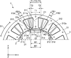
- FIG. 1 is a partial cross-sectional view schematically showing the structure of the motor 1 according to the first embodiment.
- FIG. 2 is a cross-sectional view schematically showing the structure of the electric motor 1.
- the motor 1 includes a rotor 2, a stator 3, a circuit board 4, a mold resin 5, and bearings 7a and 7b that rotatably hold the rotor 2.
- the electric motor 1 is, for example, a permanent magnet synchronous motor such as a permanent magnet embedded motor (IPM motor).
- the stator 3 is arranged outside the rotor 2.
- the stator 3 has a stator core 31, a coil 32, and an insulator 33.
- the stator core 31 is an annular core having a core back 31a extending in the circumferential direction and a plurality of teeth 31b extending in the radial direction from the core back 31a.
- the stator core 31 is composed of, for example, a plurality of thin iron plates having magnetism.
- the stator core 31 is composed of a plurality of electromagnetic steel sheets laminated in the axial direction.
- the thickness of each electrical steel plate of the stator core 31 is, for example, 0.2 mm to 0.5 mm.
- the coil 32 (that is, the winding) is wound around the insulator 33 attached to the stator core 31.
- the coil 32 is insulated by an insulator 33.
- the coil 32 is made of, for example, a material containing copper or aluminum.
- the insulator 33 is, for example, polybutylene terephthalate (PBT), polyphenylene sulfide (PPS), liquid crystal polymer (Liquid Crystal Polymer: LCP), polyethylene terephthalate resin such as Polyethylene terephthalate (PBT), polyethylene terephthalate (PBT), and polyethylene terephthalate (PBT). ing.
- the insulator 33 made of resin is, for example, an insulating film having a thickness of 0.035 mm to 0.4 mm.
- the insulator 33 is integrally molded with the stator core 31.
- the insulator 33 may be formed separately from the stator core 31. In this case, after the insulator 33 is formed, the insulator 33 is fitted into the stator core 31.
- stator core 31, the coil 32, and the insulator 33 are covered with the mold resin 5.
- the stator core 31, the coil 32, and the insulator 33 may be fixed, for example, by a cylindrical shell made of a material containing iron.
- the stator 3 and the rotor 2 are covered with a cylindrical shell by shrink fitting.
- the circuit board 4 is fixed together with the stator 3 by the mold resin 5.
- the circuit board 4 has a driving element for controlling the electric motor 1.
- the mold resin 5 integrates the circuit board 4 with the stator 3.
- the mold resin 5 is a thermosetting resin such as an unsaturated polyester resin (BMC) or an epoxy resin.
- ⁇ Rotor 2> 3 and 4 are cross-sectional views schematically showing the structure of the rotor 2.
- “N” shown in FIG. 3 indicates the N pole of the rotor 2 (specifically, the N pole that functions with respect to the stator 3), and “S” indicates the S pole of the rotor 2 (specifically, the S pole that functions with respect to the stator 3).
- the S pole) that functions with respect to the stator 3 is shown.
- the rotor 2 includes a rotor core 21, a plurality of permanent magnets 22, a shaft 23, and a non-magnetic member 24.
- the rotor 2 is rotatably arranged inside the stator 3. Specifically, the rotor 2 is arranged inside the stator 3 so that each permanent magnet 22 faces the stator 3.
- the axis of rotation of the rotor 2 coincides with the axis Ax.
- An air gap is provided between the rotor core 21 and the stator 3.
- the rotor core 21 is composed of a plurality of cores 210 stacked in the axial direction.
- the rotor core 21 (that is, the plurality of cores 210) is fixed to the non-magnetic member 24.
- the rotor core 21 may be fixed to the shaft 23.
- the shaft 23 is rotatably held by bearings 7a and 7b. When the electric motor 1 is driven, the rotor core 21 rotates together with the shaft 23.
- the rotor core 21 may be longer than the stator core 31.
- the magnetic flux from the rotor 2 (specifically, each permanent magnet 22) efficiently flows into the stator core 31.
- the rotor core 21 (that is, the plurality of cores 210) has a plurality of magnet insertion holes 21a and a shaft insertion hole 21b.
- the rotor core 21 has a plurality of magnet insertion holes 21a, and at least one permanent magnet 22 is arranged in each magnet insertion hole 21a.
- the rotor core 21 is composed of, for example, a plurality of electromagnetic steel sheets.
- each of the plurality of cores 210 is an electromagnetic steel plate.
- the plurality of cores 210 may include cores other than the electrical steel sheet.
- the rotor core 21 may be composed of a plurality of iron cores having a predetermined shape, or may be composed of a mixture of a soft magnetic material and a resin.
- Each core 210 of the rotor core 21 has a thickness of, for example, 0.2 mm to 0.5 mm.
- the cores 210 of the rotor core 21 are laminated in the axial direction.
- the plurality of magnet insertion holes 21a are formed at equal intervals in the circumferential direction of the rotor core 21.
- five magnet insertion holes 21a are provided in the rotor core 21.
- Each magnet insertion hole 21a includes a magnet arrangement portion 21c in which at least one permanent magnet 22 is arranged, and two voids 21d communicating with the magnet arrangement portion 21c in the longitudinal direction of the permanent magnet 22.
- the shaft insertion hole 21b is provided in the central portion of the rotor core 21.
- the shaft insertion hole 21b penetrates the rotor core 21 in the axial direction.
- the shaft 23 is arranged in the shaft insertion hole 21b.
- Rotor 2 is a sequential pole type rotor. That is, the rotor 2 has a first magnetic pole formed by each permanent magnet 22 and a second magnetic pole which is a pseudo magnetic pole formed by a part of the rotor core 21 between two magnet insertion holes 21a adjacent to each other. have. That is, the second magnetic pole is a pseudo magnetic pole formed by a part of the rotor core 21 adjacent to each magnet insertion hole 21a in the circumferential direction of the rotor core 21.
- the rotor 2 has a plurality of first magnetic pole regions N1 and a plurality of second magnetic pole regions S1.
- Each first magnetic pole region N1 is a region in the xy plane that includes at least a part of the permanent magnet 22 and at least a part of the magnet insertion hole 21a.
- each of the first magnetic pole regions N1 includes both ends of the surface 22a of the permanent magnet 22 and the rotation center of the rotor 2 in contact with the inner wall 211a of the magnet insertion hole 21a facing inward in the radial direction in the xy plane. It is a region between two straight lines passing through.
- Each second magnetic pole region S1 is a region between two straight lines passing through one end of each of two magnet insertion holes 21a adjacent to each other and the rotation center of the rotor 2 in the xy plane. That is, each second magnetic pole region S1 is a region that does not include the magnet insertion hole 21a and the permanent magnet 22.
- each first magnetic pole region N1 and each second magnetic pole region S1 is an interpole region.
- Each permanent magnet 22 forms an N pole as a first magnetic pole of the rotor 2.
- a part of the rotor core 21 adjacent to each magnet insertion hole 21a in the circumferential direction of the rotor core 21 forms an S pole as a second magnetic pole which is a pseudo magnetic pole of the rotor 2.
- each first magnetic pole region N1 functions as a first magnetic pole (in the present embodiment, a magnetic pole acting as an N pole with respect to the stator 3)
- each second magnetic pole region S1 is a second magnetic pole region S1. It functions as a magnetic pole of 2 (in this embodiment, a pseudo magnetic pole that acts as an S pole with respect to the stator 3).
- each first magnetic pole region N1 functions as a first polarity
- each second magnetic pole region S1 functions as a second polarity different from the first polarity.
- the number of permanent magnets 22 is half of the number n of magnetic poles of the rotor 2 (n is an even number of 4 or more).
- the number n of the magnetic poles of the rotor 2 is the total number of the magnetic poles that function as N poles with respect to the stator 3 and the number of magnetic poles that function as S poles with respect to the stator 3.
- the shaft 23 is fixed to the rotor core 21 by, for example, a non-magnetic member 24.
- the non-magnetic member 24 is arranged in the shaft insertion hole 21b.
- the non-magnetic member 24 connects the shaft 23 to the rotor core 21.
- the non-magnetic member 24 includes, for example, austenite-based stainless steel, aluminum, unsaturated polyester resin (Bulk Molding Compound: BMC), polybutylene terephthalate (PBT), polyphenylene sulfide (Polyphenylene sulfide: PPS), liquid crystal polymer, and liquid crystal polymer. : LCP), made of non-magnetic materials such as polyethylene terephthalate (PET).
- BMC unsaturated polyester resin
- PBT polybutylene terephthalate
- PPS polyphenylene sulfide
- LCP made of non-magnetic materials such as polyethylene terephthalate (PET).
- the non-magnetic member 24 is, for example, a resin.
- the non-magnetic member 24 is made of, for example, a non-magnetic resin such as unsaturated polyester resin (BMC), polybutylene terephthalate (PBT), polyphenylene sulfide (PPS), liquid crystal polymer (LCP), or polyethylene terephthalate (PET). ing.
- BMC unsaturated polyester resin
- PBT polybutylene terephthalate
- PPS polyphenylene sulfide
- LCP liquid crystal polymer
- PET polyethylene terephthalate
- Each permanent magnet 22 is, for example, a flat plate-shaped permanent magnet.
- Each permanent magnet 22 is a rare earth magnet containing, for example, neodymium or samarium.
- the permanent magnet 22 may be a ferrite magnet containing iron.
- the type of the permanent magnet 22 is not limited to the example of the present embodiment, and the permanent magnet 22 may be formed of another material.
- the permanent magnets 22 in each magnet insertion hole 21a are magnetized in the radial direction, whereby the magnetic flux from each permanent magnet 22 flows into the stator 3.
- FIG. 5 is a diagram showing a part of the motor 1 shown in FIG.
- the magnet insertion hole in the middle is referred to as “first magnet insertion hole 211”
- the magnet insertion hole on the right side is referred to as “second magnet insertion hole 212”
- the left side is referred to as “second magnet insertion hole 212”.
- the magnet insertion hole of the above is referred to as a “third magnet insertion hole 213". That is, in the xy plane, the second magnet insertion hole 212 and the third magnet insertion hole 213 are adjacent to the first magnet insertion hole 211.
- the region in contact with the permanent magnet 22 is the first magnetic pole region N1 that functions as the first magnetic pole.
- the region between the first magnet insertion hole 211 and the second magnet insertion hole 212 is a second magnetic pole region S1 that functions as a second magnetic pole that is a pseudo magnetic pole. ..
- first teeth 311 the teeth facing the first magnet insertion hole 211
- second teeth 312 the teeth located on the right side of the first teeth 311
- third tooth 313 the teeth located on the left side of the tooth 311
- Each tooth 31b has a tip surface facing the rotor core 21.
- the first tooth 311 has a tip surface 311a facing the rotor core 21
- the second tooth 312 has a tip surface 312a facing the rotor core 21
- the third tooth 313 has a tip surface 312a. It has a tip surface 313a facing the rotor core 21.
- the tip surface 311a of the first teeth 311 is also referred to as "first tip surface 311a”
- the tip surface 312a of the second teeth 312 is also referred to as “second tip surface 312a”
- the 313a is also referred to as a "third tip surface 313a”.
- the direction in which the first tooth 311 extends is referred to as the "first radial direction”
- the direction in which the second tooth 312 extends is referred to as the "second radial direction”.
- the direction in which the third teeth 313 extends is referred to as a "third radial direction”.
- the magnetic pole center line C1 indicating the center of the first magnetic pole passes through the center of the permanent magnet 22.
- the magnetic pole center line C1 passing through the magnetic pole center of the first magnetic pole coincides with the first radial direction.
- the first magnet insertion hole 211 faces the first teeth 311.
- One of the two voids 21d of each magnet insertion hole 21a faces the second tooth 312, and the other faces the third tooth 313.
- the inner wall 211a of the first magnet insertion hole 211 facing inward in the first radial direction is in contact with the surface 22a of the permanent magnet 22 facing outward in the first radial direction.
- the width M1 is the width of the surface 22a in the longitudinal direction of the permanent magnet 22 in the xy plane.
- the width M1 is the width of the surface 22a in the first direction orthogonal to the magnetic pole center line C1.
- the width W1 is the maximum width of the portion of the inner wall 211a of the first magnet insertion hole 211 that is in contact with the surface 22a of the permanent magnet 22 on the xy plane.
- the relationship between the width M1 and the width W1 is W1 ⁇ M1.
- the width W2 is the minimum width from the first magnet insertion hole 211 to the second magnet insertion hole 212 in the xy plane.
- the width T1 is the width of the first tip surface 311a of the first teeth 311 in the first direction orthogonal to the first radial direction in the xy plane. As described above, in FIG. 5, the first direction is also a direction orthogonal to the magnetic pole center line C1.
- the width T2 is the width in the first direction from the first tip surface 311a to the second tip surface 312a.
- the width T3 is the width in the first direction from the first tip surface 311a to the third tip surface 313a.
- T2 T3.
- the motor 1 satisfies W2 ⁇ W1 ⁇ M1 and T1 ⁇ W1 ⁇ T1 + 2 ⁇ T2.
- the width FB1 is the width of the gap 21d in the second direction orthogonal to the second radial direction in the xy plane.
- the width FB2 is the portion of the gap 21d in the second direction orthogonal to the second radial direction that faces the second tip surface 312a in the xy plane.
- the width of. In the example shown in FIG. 5, the relationship between the width FB1 and the width FB2 is FB1> FB2 with respect to the gap 21d facing the second tooth 312.
- the width FB3 is the width of the gap 21d in the third direction orthogonal to the third radial direction in the xy plane.
- the width FB4 is the portion of the gap 21d in the third direction orthogonal to the third radial direction that faces the third tip surface 313a in the xy plane.
- the width of. In the example shown in FIG. 5, the relationship between the width FB3 and the width FB4 is FB3> FB4 with respect to the gap 21d facing the third tooth 313.
- the width FB1 of the gap 21d facing the second teeth 312 is equal to the width FB3 of the gap 21d facing the third teeth 313, and the width of the gap 21d facing the second tip surface 312a.
- FB2 is equal to the width FB4 of the gap 21d facing the third tip surface 313a.
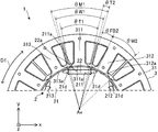
- FIG. 6 is a diagram showing the motor 1 shown in FIG. In the example shown in FIG. 6, the motor 1 satisfies ⁇ W2 ⁇ W1 ⁇ M1 and ⁇ T1 ⁇ W1 ⁇ T1 + 2 ⁇ ⁇ T2.
- angles ⁇ W2, ⁇ W1, ⁇ M1, ⁇ T1, ⁇ T2 indicate the angles corresponding to the widths W2, W1, M1, T1, T2 shown in FIG. 5, respectively.
- the angle ⁇ W2 is an angle at which two straight lines passing through two points forming the width W2 (both ends of the width W2) on the xy plane intersect at the center of rotation of the rotor 2. That is, the angle ⁇ W2 is an angle formed by a straight line passing through one end of the width W2 and the rotation center of the rotor 2 and a straight line passing through the other end of the width W2 and the rotation center of the rotor 2 in the xy plane.
- the angle ⁇ W1 is an angle at which two straight lines passing through two points forming the width W1 on the xy plane intersect at the center of rotation of the rotor 2. That is, the angle ⁇ W1 is an angle formed by a straight line passing through one end of the width W1 and the rotation center of the rotor 2 and a straight line passing through the other end of the width W1 and the rotation center of the rotor 2 in the xy plane.
- the angle ⁇ M1 is an angle at which two straight lines passing through two points forming the width M1 on the xy plane intersect at the center of rotation of the rotor 2. That is, the angle ⁇ M1 is an angle formed by a straight line passing through one end of the width M1 and the rotation center of the rotor 2 and a straight line passing through the other end of the width M1 and the rotation center of the rotor 2 in the xy plane.
- the angle ⁇ T1 is an angle at which two straight lines passing through two points forming the width T1 on the xy plane intersect at the center of rotation of the rotor 2. That is, the angle ⁇ T1 is an angle formed by a straight line passing through one end of the width T1 and the rotation center of the rotor 2 and a straight line passing through the other end of the width T1 and the rotation center of the rotor 2 in the xy plane.
- the angle ⁇ T2 is an angle at which two straight lines passing through two points forming the width T2 on the xy plane intersect at the center of rotation of the rotor 2. That is, the angle ⁇ T2 is an angle formed by a straight line passing through one end of the width T2 and the rotation center of the rotor 2 and a straight line passing through the other end of the width T2 and the rotation center of the rotor 2 in the xy plane.
- the angle ⁇ FB2 indicates an angle corresponding to the width FB2 shown in FIG.
- the angle ⁇ FB2 is an angle at which two straight lines passing through two points forming the width FB2 on the xy plane intersect at the center of rotation of the rotor 2. That is, the angle ⁇ FB2 is an angle formed by a straight line passing through one end of the width FB2 and the rotation center of the rotor 2 and a straight line passing through the other end of the width FB2 and the rotation center of the rotor 2 in the xy plane.
- FIG. 7 is a cross-sectional view showing an electric motor 1a according to a comparative example.
- the rotor 2a is different from the rotor 2 of the motor 1 according to the present embodiment.
- the rotor 2a of the motor 1a according to the comparative example is not a sequential pole type rotor but a normal IPM (Interior Permanent Magnet) rotor. That is, in the rotor 2a of the motor 1a according to the comparative example, the permanent magnet 22 that functions as the first magnetic pole (for example, N pole) with respect to the stator 3 and the second magnetic pole (for example, S pole) for the stator 3.
- Permanent magnets 22 that function as the above are arranged alternately in the circumferential direction.
- the width M1 in the longitudinal direction of each permanent magnet increases, the magnetic force of the permanent magnet increases and the output of the rotor increases.
- the width M1 in the longitudinal direction of each permanent magnet specifically, the width of each permanent magnet in the circumferential direction is L / n (L: circle of the rotor core) at the maximum. Circumference, n: number of magnetic poles).
- the rotor 2 of the motor 1 according to the present embodiment satisfies W2 ⁇ W1 ⁇ M1 as shown in FIG. Therefore, in the rotor 2 of the motor 1 according to the present embodiment, the width M1 of the permanent magnet 22 forming the first magnetic pole can be increased as compared with the comparative example. As a result, the efficiency of the rotor 2 can be improved with fewer permanent magnets 22 than in the comparative example.
- the motor 1 according to the present embodiment satisfies T1 ⁇ W1 as shown in FIG. Therefore, in the example shown in FIG. 5, the effective magnetic flux flowing from each permanent magnet 22 to the first tooth 311 which is the target tooth can be increased.
- the width W1 is larger than T1 + 2 ⁇ T2
- the magnetic flux from the permanent magnet 22 flows into the teeth that are not the target teeth, and the leakage flux increases.
- the width W1 is larger than T1 + 2 ⁇ T2
- the magnetic flux from the permanent magnet 22 flows into the second teeth 312 and the third teeth 313, and the leakage flux increases.
- the electric motor 1 according to the present embodiment satisfies W1 ⁇ T1 + 2 ⁇ T2. Therefore, in the example shown in FIG. 5, it is possible to reduce the leakage flux flowing into the second tooth 312 and the third tooth 313 adjacent to the first tooth 311 which is the target tooth.
- the motor 1 according to the present embodiment satisfies W2 ⁇ W1 ⁇ M1 and T1 ⁇ W1 ⁇ T1 + 2 ⁇ T2. Therefore, it is possible to increase the effective magnetic flux flowing from each permanent magnet 22 into the target tooth and reduce the leakage flux flowing into the tooth adjacent to the target tooth.
- the leakage flux flowing from the permanent magnet 22 arranged in the first magnet insertion hole 211 to the second tooth 312 can be reduced. Therefore, it is possible to increase the effective magnetic flux flowing from each permanent magnet 22 into the target tooth and reduce the leakage flux flowing into the tooth adjacent to the target tooth.
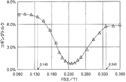
- FIG. 8 is a graph showing the relationship between the ratio FB2 / T1 of the width FB2 of the gap 21d facing the second tip surface 312a to the width T1 of the first tip surface 311a and the cogging torque generated in the motor 1.
- the motor 1 satisfies 0.14 ⁇ FB2 / T1 ⁇ 0.34. With this configuration, the cogging torque in the motor 1 can be reduced. As a result, vibration and noise due to cogging torque in the motor 1 can be reduced.
- FIG. 9 shows the relationship between the ratio FB2 / T1 of the width FB2 of the gap 21d facing the second tip surface 312a to the width T1 of the first tip surface 311a and the cogging torque, and the width T1 of the first tip surface 311a. It is a graph which shows the relationship between the ratio FB2 / T1 of the width FB2 of the gap 21d facing the 2nd tip surface 312a with respect to the torque of the motor 1.
- the maximum value of torque is 1.000.
- the electric motor 1 satisfies 0.165 ⁇ FB2 / T1 ⁇ 0.285. With this configuration, the cogging torque in the motor 1 can be reduced while maintaining the maximum torque of the motor 1. As a result, vibration and noise due to cogging torque in the motor 1 can be reduced while maintaining the maximum torque of the motor 1.
- the motor 1 satisfies 0.175 ⁇ FB2 / T1 ⁇ 0.24. With this configuration, it is possible to suppress a decrease in the maximum torque of the motor 1, and it is possible to effectively reduce the cogging torque in the motor 1. As a result, it is possible to suppress a decrease in the maximum torque of the motor 1, and it is possible to effectively reduce vibration and noise due to cogging torque in the motor 1.
- the motor 1 according to the present embodiment satisfies ⁇ W2 ⁇ W1 ⁇ M1 and ⁇ T1 ⁇ W1 ⁇ T1 + 2 ⁇ ⁇ T2. Therefore, in the example shown in FIG. 6, the effective magnetic flux flowing from each permanent magnet 22 into the target tooth is increased and flows into the second tooth 312 and the third tooth 313 adjacent to the first tooth 311 which is the target tooth. The leakage flux can be reduced.
- FIG. 10 shows the relationship between the ratio ⁇ FB2 / ⁇ T1 of the angle ⁇ FB2 corresponding to the width FB2 to the angle ⁇ T1 corresponding to the width T1 and the cogging torque, and the ratio ⁇ FB2 of the angle ⁇ FB2 corresponding to the width FB2 to the angle ⁇ T1 corresponding to the width T1.
- the maximum value of torque is 1.000.
- the motor 1 satisfies 0.165 ⁇ FB2 / ⁇ T1 ⁇ 0.285.
- the cogging torque in the motor 1 can be reduced while maintaining the maximum torque of the motor 1.
- vibration and noise due to cogging torque in the motor 1 can be reduced while maintaining the maximum torque of the motor 1.
- the motor 1 satisfies 0.175 ⁇ FB2 / ⁇ T1 ⁇ 0.24. With this configuration, it is possible to suppress a decrease in the maximum torque of the motor 1, and it is possible to effectively reduce the cogging torque in the motor 1. As a result, it is possible to suppress a decrease in the maximum torque of the motor 1, and it is possible to effectively reduce vibration and noise due to cogging torque in the motor 1.
- FIG. 11 is a diagram schematically showing the structure of the fan 60 according to the second embodiment.
- the fan 60 has a blade 61 and an electric motor 62.
- the fan 60 is also referred to as a blower.
- the electric motor 62 is the electric motor 1 according to the first embodiment.
- the blades 61 are fixed to the shaft of the motor 62.
- the electric motor 62 drives the blades 61. Specifically, the electric motor 62 rotates the blades 61. When the motor 62 is driven, the blades 61 rotate to generate an air flow. As a result, the fan 60 can blow air.
- the electric motor 1 described in the first embodiment is applied to the electric motor 62, the same advantages as those described in the first embodiment can be obtained. Further, it is possible to prevent a decrease in the efficiency of the fan 60.
- Embodiment 3 The air conditioner 50 (also referred to as a refrigerating air conditioner or a refrigerating cycle device) according to the third embodiment will be described.
- FIG. 12 is a diagram schematically showing the configuration of the air conditioner 50 according to the third embodiment.
- FIG. 13 is a diagram schematically showing the main components in the outdoor unit 53 as a blower of the air conditioner 50.
- the air conditioner 50 includes an indoor unit 51 as a blower (first blower), a refrigerant pipe 52, and an outdoor unit 53 as a blower (second blower) connected to the indoor unit 51. And.
- the outdoor unit 53 is connected to the indoor unit 51 through a refrigerant pipe 52.
- the indoor unit 51 includes an electric motor 51a (for example, the electric motor 1 according to the first embodiment), a blower portion 51b that blows air by being driven by the electric motor 51a, and a housing 51c that covers the electric motor 51a and the blower portion 51b. ..
- the blower portion 51b has, for example, blades 51d driven by an electric motor 51a.
- the blades 51d are fixed to the shaft of the motor 51a and generate an air flow.
- the outdoor unit 53 includes an electric motor 53a (for example, the electric motor 1 according to the first embodiment), a blower 53b, a compressor 54, a heat exchanger (not shown), a blower 53b, a compressor 54, and heat. It has a housing 53c that covers the exchanger.
- the blower unit 53b blows air by being driven by the electric motor 53a.
- the blower portion 53b has, for example, a blade 53d driven by an electric motor 53a.
- the blades 53d are fixed to the shaft of the motor 53a and generate an air flow.
- the compressor 54 includes an electric motor 54a (for example, the electric motor 1 according to the first embodiment), a compression mechanism 54b (for example, a refrigerant circuit) driven by the electric motor 54a, and a housing 54c that covers the electric motor 54a and the compression mechanism 54b.
- an electric motor 54a for example, the electric motor 1 according to the first embodiment
- a compression mechanism 54b for example, a refrigerant circuit driven by the electric motor 54a
- a housing 54c that covers the electric motor 54a and the compression mechanism 54b.
- the indoor unit 51 and the outdoor unit 53 has the motor 1 described in the first embodiment. That is, the indoor unit 51, the outdoor unit 53, or both of them have the electric motor 1 described in the first embodiment.
- the motor 1 described in the first embodiment is applied to at least one of the motors 51a and 53a. That is, the motor 1 described in the first embodiment is applied to the indoor unit 51, the outdoor unit 53, or both of them.
- the motor 1 described in the first embodiment may be applied to the motor 54a of the compressor 54.
- the air conditioner 50 can perform air conditioning such as a cooling operation in which cold air is blown from the indoor unit 51 and a heating operation in which warm air is blown, for example.
- the motor 51a is a drive source for driving the blower portion 51b.
- the blower portion 51b can blow the adjusted air.
- the electric motor 53a is fixed to the housing 53c of the outdoor unit 53 by, for example, a screw 53e.
- the same advantages as those described in the first embodiment can be obtained. Can be done. As a result, it is possible to prevent a decrease in the efficiency of the air conditioner 50.
- the motor 1 according to the first embodiment when used as the drive source of the blower (for example, the indoor unit 51), the same advantages as those described in the first embodiment can be obtained. As a result, it is possible to prevent a decrease in the efficiency of the blower.
- the blower having the motor 1 according to the first embodiment and the blades (for example, blades 51d or 53d) driven by the motor 1 can be used alone as a blower device. This blower can be applied to equipment other than the air conditioner 50.
- the motor 1 according to the first embodiment is used as the drive source of the compressor 54, the same advantages as those described in the first embodiment can be obtained. As a result, it is possible to prevent a decrease in the efficiency of the compressor 54.
- the electric motor 1 described in the first embodiment can be mounted on a device having a drive source, such as a ventilation fan, a home electric appliance, or a machine tool, in addition to the air conditioner 50.
- a drive source such as a ventilation fan, a home electric appliance, or a machine tool, in addition to the air conditioner 50.
Abstract
Description
第1の磁石挿入孔及び前記第1の磁石挿入孔に隣接する第2の磁石挿入孔を有するロータコアと、前記第1の磁石挿入孔に配置された永久磁石と、第1の磁極として機能する第1の磁極領域と、前記第1の磁石挿入孔と前記第2の磁石挿入孔との間の前記ロータコアの一部によって形成される疑似磁極である第2の磁極として機能する第2の磁極領域とを有するコンシクエントポール型ロータと、
周方向に延在するコアバックと、前記コアバックから前記コンシクエントポール型ロータの第1の径方向に延在する第1のティースと、前記第1のティースに隣接している第2のティースとを有し、前記コンシクエントポール型ロータの外側に配置されたステータと
を備え、
前記第1の径方向における内側に面する前記第1の磁石挿入孔の内壁は、前記第1の径方向における外側に面する前記永久磁石の表面に接触しており、
前記コンシクエントポール型ロータの軸方向と直交する平面において、前記永久磁石の長手方向における前記表面の幅をM1とし、
前記平面において、前記第1の磁石挿入孔の前記内壁のうちの、前記永久磁石の前記表面に接触している部分の最大幅をW1とし、
前記平面において、前記第1の磁石挿入孔から前記第2の磁石挿入孔までの最小幅をW2とし、
前記第1のティースのうちの前記ロータコアに面する第1の先端面の、前記平面において前記第1の径方向と直交する第1の方向における幅をT1とし、
前記第1の先端面から前記第2のティースのうちの前記ロータコアに面する第2の先端面までの前記第1の方向における幅をT2としたとき、
W2<W1<M1、且つT1<W1<T1+2×T2
を満たす。
本開示の他の態様に係る電動機は、
第1の磁石挿入孔及び前記第1の磁石挿入孔に隣接する第2の磁石挿入孔を有するロータコアと、前記第1の磁石挿入孔に配置された永久磁石と、第1の磁極として機能する第1の磁極領域と、前記第1の磁石挿入孔と前記第2の磁石挿入孔との間の前記ロータコアの一部によって形成される疑似磁極である第2の磁極として機能する第2の磁極領域とを有するコンシクエントポール型ロータと、
周方向に延在するコアバックと、前記コアバックから前記コンシクエントポール型ロータの第1の径方向に延在する第1のティースと、前記第1のティースに隣接している第2のティースとを有し、前記コンシクエントポール型ロータの外側に配置されたステータと
を備え、
前記第1の径方向における内側に面する前記第1の磁石挿入孔の内壁は、前記第1の径方向における外側に面する前記永久磁石の表面に接触しており、
前記コンシクエントポール型ロータの軸方向と直交する平面において、前記永久磁石の長手方向における前記表面の幅をM1とし、
前記平面において、前記第1の磁石挿入孔の前記内壁のうちの、前記永久磁石の前記表面に接触している部分の最大幅をW1とし、
前記平面において、前記第1の磁石挿入孔から前記第2の磁石挿入孔までの最小幅をW2とし、
前記第1のティースのうちの前記ロータコアに面する第1の先端面の、前記平面において前記第1の径方向と直交する第1の方向における幅をT1とし、
前記第1の先端面から前記第2のティースのうちの前記ロータコアに面する第2の先端面までの前記第1の方向における幅をT2とし、
前記平面において、前記最大幅W1をなす2つの点をそれぞれ通る2直線が、前記コンシクエントポール型ロータの回転中心で交差する角度をθW1とし、
前記平面において、前記最小幅W2をなす2つの点をそれぞれ通る2直線が、前記回転中心で交差する角度をθW2とし、
前記平面において、前記幅M1をなす2つの点をそれぞれ通る2直線が、前記回転中心で交差する角度をθM1とし、
前記平面において、前記幅T1をなす2つの点をそれぞれ通る2直線が、前記回転中心で交差する角度をθT1とし、
前記平面において、前記幅T2をなす2つの点をそれぞれ通る2直線が、前記回転中心で交差する角度をθT2としたとき、
θW2<θW1<θM1、且つθT1<θW1<θT1+2×θT2を満たす。
本開示の他の態様に係るファンは、
羽根と、
前記羽根を駆動する前記電動機と
を備える。
本開示の他の態様に係る空気調和機は、
室内機と、
前記室内機に接続された室外機と
を備え、
前記室内機、前記室外機、又は前記室内機及び前記室外機の両方は、前記電動機を有する。 The motor according to one aspect of the present disclosure is
A rotor core having a first magnet insertion hole and a second magnet insertion hole adjacent to the first magnet insertion hole, a permanent magnet arranged in the first magnet insertion hole, and functioning as a first magnetic pole. A second magnetic pole that functions as a second magnetic pole that is a pseudo magnetic pole formed by a part of the rotor core between the first magnetic pole region and the first magnet insertion hole and the second magnet insertion hole. Consequential pole type rotor with area and
A core back extending in the circumferential direction, a first tooth extending from the core back in the first radial direction of the sequential pole type rotor, and a second tooth adjacent to the first tooth. And with a stator located on the outside of the sequential pole type rotor.
The inner wall of the first magnet insertion hole facing inward in the first radial direction is in contact with the surface of the permanent magnet facing outward in the first radial direction.
In a plane orthogonal to the axial direction of the sequential pole type rotor, the width of the surface in the longitudinal direction of the permanent magnet is M1.
In the plane, the maximum width of the portion of the inner wall of the first magnet insertion hole in contact with the surface of the permanent magnet is W1.
In the plane, the minimum width from the first magnet insertion hole to the second magnet insertion hole is W2.
The width of the first tip surface of the first teeth facing the rotor core in the first direction orthogonal to the first radial direction in the plane is defined as T1.
When the width in the first direction from the first tip surface to the second tip surface of the second tooth facing the rotor core is T2.
W2 <W1 <M1 and T1 <W1 <T1 + 2 × T2
Meet.
The motor according to another aspect of the present disclosure is
A rotor core having a first magnet insertion hole and a second magnet insertion hole adjacent to the first magnet insertion hole, a permanent magnet arranged in the first magnet insertion hole, and functioning as a first magnetic pole. A second magnetic pole that functions as a second magnetic pole that is a pseudo magnetic pole formed by a part of the rotor core between the first magnetic pole region and the first magnet insertion hole and the second magnet insertion hole. Consequential pole type rotor with area and
A core back extending in the circumferential direction, a first tooth extending from the core back in the first radial direction of the sequential pole type rotor, and a second tooth adjacent to the first tooth. And with a stator located on the outside of the sequential pole type rotor.
The inner wall of the first magnet insertion hole facing inward in the first radial direction is in contact with the surface of the permanent magnet facing outward in the first radial direction.
In a plane orthogonal to the axial direction of the sequential pole type rotor, the width of the surface in the longitudinal direction of the permanent magnet is M1.
In the plane, the maximum width of the portion of the inner wall of the first magnet insertion hole in contact with the surface of the permanent magnet is W1.
In the plane, the minimum width from the first magnet insertion hole to the second magnet insertion hole is W2.
The width of the first tip surface of the first teeth facing the rotor core in the first direction orthogonal to the first radial direction in the plane is defined as T1.
The width in the first direction from the first tip surface to the second tip surface of the second tooth facing the rotor core is defined as T2.
In the plane, the angle at which two straight lines passing through the two points forming the maximum width W1 intersect at the rotation center of the sequential pole type rotor is defined as θW1.
In the plane, the angle at which two straight lines passing through the two points forming the minimum width W2 intersect at the center of rotation is set to θW2.
In the plane, the angle at which two straight lines passing through the two points forming the width M1 intersect at the center of rotation is set to θM1.
In the plane, the angle at which two straight lines passing through the two points forming the width T1 intersect at the center of rotation is set to θT1.
When the angle at which two straight lines passing through the two points forming the width T2 intersect at the center of rotation on the plane is θT2.
Satisfy θW2 <θW1 <θM1 and θT1 <θW1 <θT1 + 2 × θT2.
Fans according to other aspects of the present disclosure
Feathers and
The electric motor for driving the blades is provided.
The air conditioner according to another aspect of the present disclosure is
Indoor unit and
It is equipped with an outdoor unit connected to the indoor unit.
The indoor unit, the outdoor unit, or both the indoor unit and the outdoor unit have the electric motor.
実施の形態1に係る電動機1について説明する。
各図に示されるxyz直交座標系において、z軸方向(z軸)は、電動機1の軸線Axと平行な方向を示し、x軸方向(x軸)は、z軸方向(z軸)に直交する方向を示し、y軸方向(y軸)は、z軸方向及びx軸方向の両方に直交する方向を示す。軸線Axは、ロータ2の回転中心、すなわち、ロータ2の回転軸である。軸線Axと平行な方向は、「ロータ2の軸方向」又は単に「軸方向」とも称する。径方向は、ロータ2又はステータ3の半径方向であり、軸線Axと直交する方向である。xy平面は、軸方向と直交する平面である。矢印D1は、軸線Axを中心とする周方向を示す。ロータ2又はステータ3の周方向を、単に「周方向」とも称する。
The
In the xyz Cartesian coordinate system shown in each figure, the z-axis direction (z-axis) indicates a direction parallel to the axis Ax of the
図1は、実施の形態1に係る電動機1の構造を概略的に示す部分断面図である。
図2は、電動機1の構造を概略的に示す断面図である。
電動機1は、ロータ2と、ステータ3と、回路基板4と、モールド樹脂5と、ロータ2を回転可能に保持するベアリング7a及び7bとを有する。電動機1は、例えば、永久磁石埋込型電動機(IPMモータ)などの永久磁石同期電動機である。 <
FIG. 1 is a partial cross-sectional view schematically showing the structure of the
FIG. 2 is a cross-sectional view schematically showing the structure of the
The
ステータ3は、ロータ2の外側に配置されている。ステータ3は、ステータコア31と、コイル32と、インシュレータ33とを有する。ステータコア31は、周方向に延在するコアバック31aと、コアバック31aから径方向に延在する複数のティース31bとを有する環状のコアである。 <
The
図3及び図4は、ロータ2の構造を概略的に示す断面図である。図3に示される「N」は、ロータ2のN極(具体的には、ステータ3に対して機能するN極)を示し、「S」は、ロータ2のS極(具体的には、ステータ3に対して機能するS極)を示す。
ロータ2は、ロータコア21と、複数の永久磁石22と、シャフト23と、非磁性部材24とを有する。ロータ2は、ステータ3の内側に回転可能に配置されている。具体的には、各永久磁石22がステータ3に面するように、ロータ2がステータ3の内側に配置されている。ロータ2の回転軸は、軸線Axと一致する。エアギャップがロータコア21とステータ3との間に設けられている。 <
3 and 4 are cross-sectional views schematically showing the structure of the
The
図5において、3つの磁石挿入孔のうちの、真ん中の磁石挿入孔を「第1の磁石挿入孔211」と称し、右側の磁石挿入孔を「第2の磁石挿入孔212」と称し、左側の磁石挿入孔を「第3の磁石挿入孔213」と称する。すなわち、xy平面において、第2の磁石挿入孔212及び第3の磁石挿入孔213は、第1の磁石挿入孔211に隣接している。 FIG. 5 is a diagram showing a part of the
In FIG. 5, of the three magnet insertion holes, the magnet insertion hole in the middle is referred to as "first
図6に示される例において、電動機1は、θW2<θW1<θM1、且つθT1<θW1<θT1+2×θT2を満たす。 FIG. 6 is a diagram showing the
In the example shown in FIG. 6, the
図7は、比較例に係る電動機1aを示す断面図である。
比較例に係る電動機1aでは、ロータ2aが、本実施の形態に係る電動機1のロータ2と異なる。具体的には、比較例に係る電動機1aのロータ2aは、コンシクエントポール型ロータではなく、通常のIPM(Interior Permanent Magnet)ロータである。すなわち、比較例に係る電動機1aのロータ2aでは、ステータ3に対して第1の磁極(例えば、N極)として機能する永久磁石22とステータ3に対して第2の磁極(例えば、S極)として機能する永久磁石22とが、周方向に交互に配列されている。 <Advantages of
FIG. 7 is a cross-sectional view showing an
In the
図8に示されるように、電動機1は、0.14<FB2/T1<0.34を満たすことが望ましい。この構成により、電動機1におけるコギングトルクを低減することできる。その結果、電動機1におけるコギングトルクによる振動及び騒音を低減することができる。 FIG. 8 is a graph showing the relationship between the ratio FB2 / T1 of the width FB2 of the
As shown in FIG. 8, it is desirable that the
図9に示されるように、電動機1は、0.165<FB2/T1<0.285を満たすことが望ましい。この構成により、電動機1の最大トルクを維持しながら、電動機1におけるコギングトルクを低減することできる。その結果、電動機1の最大トルクを維持しながら、電動機1におけるコギングトルクによる振動及び騒音を低減することができる。 FIG. 9 shows the relationship between the ratio FB2 / T1 of the width FB2 of the
As shown in FIG. 9, it is desirable that the
図10に示されるように、電動機1は、0.14<θFB2/θT1<0.34を満たすことが望ましい。この構成により、電動機1におけるコギングトルクを低減することできる。その結果、電動機1におけるコギングトルクによる振動及び騒音を低減することができる。 FIG. 10 shows the relationship between the ratio θFB2 / θT1 of the angle θFB2 corresponding to the width FB2 to the angle θT1 corresponding to the width T1 and the cogging torque, and the ratio θFB2 of the angle θFB2 corresponding to the width FB2 to the angle θT1 corresponding to the width T1. It is a graph which shows the relationship between / θT1 and the torque of a
As shown in FIG. 10, it is desirable that the
図11は、実施の形態2に係るファン60の構造を概略的に示す図である。
ファン60は、羽根61と、電動機62とを有する。ファン60は、送風機とも称する。電動機62は、実施の形態1に係る電動機1である。羽根61は、電動機62のシャフトに固定されている。電動機62は、羽根61を駆動する。具体的には、電動機62は、羽根61を回転させる。電動機62が駆動すると、羽根61が回転し、気流が生成される。これにより、ファン60は送風することができる。
FIG. 11 is a diagram schematically showing the structure of the
The
実施の形態3に係る空気調和機50(冷凍空調装置又は冷凍サイクル装置とも称する)について説明する。
図12は、実施の形態3に係る空気調和機50の構成を概略的に示す図である。
図13は、空気調和機50の送風機としての室外機53内の主要な構成要素を概略的に示す図である。
The air conditioner 50 (also referred to as a refrigerating air conditioner or a refrigerating cycle device) according to the third embodiment will be described.
FIG. 12 is a diagram schematically showing the configuration of the
FIG. 13 is a diagram schematically showing the main components in the
Claims (11)
- 第1の磁石挿入孔及び前記第1の磁石挿入孔に隣接する第2の磁石挿入孔を有するロータコアと、前記第1の磁石挿入孔に配置された永久磁石と、第1の磁極として機能する第1の磁極領域と、前記第1の磁石挿入孔と前記第2の磁石挿入孔との間の前記ロータコアの一部によって形成される疑似磁極である第2の磁極として機能する第2の磁極領域とを有するコンシクエントポール型ロータと、
周方向に延在するコアバックと、前記コアバックから前記コンシクエントポール型ロータの第1の径方向に延在する第1のティースと、前記第1のティースに隣接している第2のティースとを有し、前記コンシクエントポール型ロータの外側に配置されたステータと
を備え、
前記第1の径方向における内側に面する前記第1の磁石挿入孔の内壁は、前記第1の径方向における外側に面する前記永久磁石の表面に接触しており、
前記コンシクエントポール型ロータの軸方向と直交する平面において、前記永久磁石の長手方向における前記表面の幅をM1とし、
前記平面において、前記第1の磁石挿入孔の前記内壁のうちの、前記永久磁石の前記表面に接触している部分の最大幅をW1とし、
前記平面において、前記第1の磁石挿入孔から前記第2の磁石挿入孔までの最小幅をW2とし、
前記第1のティースのうちの前記ロータコアに面する第1の先端面の、前記平面において前記第1の径方向と直交する第1の方向における幅をT1とし、
前記第1の先端面から前記第2のティースのうちの前記ロータコアに面する第2の先端面までの前記第1の方向における幅をT2としたとき、
W2<W1<M1、且つT1<W1<T1+2×T2
を満たす電動機。 A rotor core having a first magnet insertion hole and a second magnet insertion hole adjacent to the first magnet insertion hole, a permanent magnet arranged in the first magnet insertion hole, and functioning as a first magnetic pole. A second magnetic pole that functions as a second magnetic pole that is a pseudo magnetic pole formed by a part of the rotor core between the first magnetic pole region and the first magnet insertion hole and the second magnet insertion hole. Consequential pole type rotor with area and
A core back extending in the circumferential direction, a first tooth extending from the core back in the first radial direction of the sequential pole type rotor, and a second tooth adjacent to the first tooth. And with a stator located on the outside of the sequential pole type rotor.
The inner wall of the first magnet insertion hole facing inward in the first radial direction is in contact with the surface of the permanent magnet facing outward in the first radial direction.
In a plane orthogonal to the axial direction of the sequential pole type rotor, the width of the surface in the longitudinal direction of the permanent magnet is M1.
In the plane, the maximum width of the portion of the inner wall of the first magnet insertion hole in contact with the surface of the permanent magnet is W1.
In the plane, the minimum width from the first magnet insertion hole to the second magnet insertion hole is W2.
The width of the first tip surface of the first teeth facing the rotor core in the first direction orthogonal to the first radial direction in the plane is defined as T1.
When the width in the first direction from the first tip surface to the second tip surface of the second tooth facing the rotor core is T2.
W2 <W1 <M1 and T1 <W1 <T1 + 2 × T2
Motor that meets. - 前記第1の磁石挿入孔は、前記永久磁石が配置された磁石配置部と、前記永久磁石の前記長手方向において前記磁石配置部に連通しており前記第2のティースに対向する空隙とを含み、
前記平面において、前記第1の磁極の磁極中心を通る磁極中心線と前記第1の径方向とが一致している場合において、
前記平面において、前記空隙のうちの前記第2の先端面に対向する部分の、前記コアバックから前記第2のティースが延在する第2の径方向と直交する方向における幅をFB2としたとき、
0.14<FB2/T1<0.34
を満たす請求項1に記載の電動機。 The first magnet insertion hole includes a magnet arrangement portion in which the permanent magnet is arranged and a gap communicating with the magnet arrangement portion in the longitudinal direction of the permanent magnet and facing the second tooth. ,
In the plane, when the magnetic pole center line passing through the magnetic pole center of the first magnetic pole coincides with the first radial direction.
When the width of the portion of the gap facing the second tip surface in the plane in a direction orthogonal to the second radial direction in which the second tooth extends from the core back is defined as FB2. ,
0.14 <FB2 / T1 <0.34
The motor according to claim 1. - 前記第1の磁石挿入孔は、前記永久磁石が配置された磁石配置部と、前記永久磁石の前記長手方向において前記磁石配置部に連通する空隙とを含み、
前記平面において、前記第1の磁極の磁極中心を通る磁極中心線と前記第1の径方向とが一致している場合において、
前記平面において、前記空隙のうちの前記第2の先端面に対向する部分の、前記コアバックから前記第2のティースが延在する第2の径方向と直交する方向における幅をFB2としたとき、
0.165<FB2/T1<0.285
を満たす請求項1に記載の電動機。 The first magnet insertion hole includes a magnet arrangement portion in which the permanent magnet is arranged and a gap communicating with the magnet arrangement portion in the longitudinal direction of the permanent magnet.
In the plane, when the magnetic pole center line passing through the magnetic pole center of the first magnetic pole coincides with the first radial direction.
When the width of the portion of the gap facing the second tip surface in the plane in a direction orthogonal to the second radial direction in which the second tooth extends from the core back is defined as FB2. ,
0.165 <FB2 / T1 <0.285
The motor according to claim 1. - 前記第1の磁石挿入孔は、前記永久磁石が配置された磁石配置部と、前記永久磁石の前記長手方向において前記磁石配置部に連通する空隙とを含み、
前記平面において、前記第1の磁極の磁極中心を通る磁極中心線と前記第1の径方向とが一致している場合において、
前記平面において、前記空隙のうちの前記第2の先端面に対向する部分の、前記コアバックから前記第2のティースが延在する第2の径方向と直交する方向における幅をFB2としたとき、
0.175<FB2/T1<0.24
を満たす請求項1に記載の電動機。 The first magnet insertion hole includes a magnet arrangement portion in which the permanent magnet is arranged and a gap communicating with the magnet arrangement portion in the longitudinal direction of the permanent magnet.
In the plane, when the magnetic pole center line passing through the magnetic pole center of the first magnetic pole coincides with the first radial direction.
When the width of the portion of the gap facing the second tip surface in the plane in a direction orthogonal to the second radial direction in which the second tooth extends from the core back is defined as FB2. ,
0.175 <FB2 / T1 <0.24
The motor according to claim 1. - 第1の磁石挿入孔及び前記第1の磁石挿入孔に隣接する第2の磁石挿入孔を有するロータコアと、前記第1の磁石挿入孔に配置された永久磁石と、第1の磁極として機能する第1の磁極領域と、前記第1の磁石挿入孔と前記第2の磁石挿入孔との間の前記ロータコアの一部によって形成される疑似磁極である第2の磁極として機能する第2の磁極領域とを有するコンシクエントポール型ロータと、
周方向に延在するコアバックと、前記コアバックから前記コンシクエントポール型ロータの第1の径方向に延在する第1のティースと、前記第1のティースに隣接している第2のティースとを有し、前記コンシクエントポール型ロータの外側に配置されたステータと
を備え、
前記第1の径方向における内側に面する前記第1の磁石挿入孔の内壁は、前記第1の径方向における外側に面する前記永久磁石の表面に接触しており、
前記コンシクエントポール型ロータの軸方向と直交する平面において、前記永久磁石の長手方向における前記表面の幅をM1とし、
前記平面において、前記第1の磁石挿入孔の前記内壁のうちの、前記永久磁石の前記表面に接触している部分の最大幅をW1とし、
前記平面において、前記第1の磁石挿入孔から前記第2の磁石挿入孔までの最小幅をW2とし、
前記第1のティースのうちの前記ロータコアに面する第1の先端面の、前記平面において前記第1の径方向と直交する第1の方向における幅をT1とし、
前記第1の先端面から前記第2のティースのうちの前記ロータコアに面する第2の先端面までの前記第1の方向における幅をT2とし、
前記平面において、前記最大幅W1をなす2つの点をそれぞれ通る2直線が、前記コンシクエントポール型ロータの回転中心で交差する角度をθW1とし、
前記平面において、前記最小幅W2をなす2つの点をそれぞれ通る2直線が、前記回転中心で交差する角度をθW2とし、
前記平面において、前記幅M1をなす2つの点をそれぞれ通る2直線が、前記回転中心で交差する角度をθM1とし、
前記平面において、前記幅T1をなす2つの点をそれぞれ通る2直線が、前記回転中心で交差する角度をθT1とし、
前記平面において、前記幅T2をなす2つの点をそれぞれ通る2直線が、前記回転中心で交差する角度をθT2としたとき、
θW2<θW1<θM1、且つθT1<θW1<θT1+2×θT2を満たす
電動機。 A rotor core having a first magnet insertion hole and a second magnet insertion hole adjacent to the first magnet insertion hole, a permanent magnet arranged in the first magnet insertion hole, and functioning as a first magnetic pole. A second magnetic pole that functions as a second magnetic pole that is a pseudo magnetic pole formed by a part of the rotor core between the first magnetic pole region and the first magnet insertion hole and the second magnet insertion hole. Consequential pole type rotor with area and
A core back extending in the circumferential direction, a first tooth extending from the core back in the first radial direction of the sequential pole type rotor, and a second tooth adjacent to the first tooth. And with a stator located on the outside of the sequential pole type rotor.
The inner wall of the first magnet insertion hole facing inward in the first radial direction is in contact with the surface of the permanent magnet facing outward in the first radial direction.
In a plane orthogonal to the axial direction of the sequential pole type rotor, the width of the surface in the longitudinal direction of the permanent magnet is M1.
In the plane, the maximum width of the portion of the inner wall of the first magnet insertion hole in contact with the surface of the permanent magnet is W1.
In the plane, the minimum width from the first magnet insertion hole to the second magnet insertion hole is W2.
The width of the first tip surface of the first teeth facing the rotor core in the first direction orthogonal to the first radial direction in the plane is defined as T1.
The width in the first direction from the first tip surface to the second tip surface of the second tooth facing the rotor core is defined as T2.
In the plane, the angle at which two straight lines passing through the two points forming the maximum width W1 intersect at the rotation center of the sequential pole type rotor is defined as θW1.
In the plane, the angle at which two straight lines passing through the two points forming the minimum width W2 intersect at the center of rotation is set to θW2.
In the plane, the angle at which two straight lines passing through the two points forming the width M1 intersect at the center of rotation is set to θM1.
In the plane, the angle at which two straight lines passing through the two points forming the width T1 intersect at the center of rotation is set to θT1.
When the angle at which two straight lines passing through the two points forming the width T2 intersect at the center of rotation on the plane is θT2.
An electric motor that satisfies θW2 <θW1 <θM1 and θT1 <θW1 <θT1 + 2 × θT2. - 前記第1の磁石挿入孔は、前記永久磁石が配置された磁石配置部と、前記永久磁石の前記長手方向において前記磁石配置部に連通しており前記第2のティースに対向する空隙とを含み、
前記平面において、前記第1の磁極の磁極中心を通る磁極中心線と前記第1の径方向とが一致している場合において、
前記平面において、前記空隙のうちの前記第2の先端面に対向する部分の、前記コアバックから前記第2のティースが延在する第2の径方向と直交する方向における幅をFB2とし、
前記平面において、前記幅FB2をなす2つの点をそれぞれ通る2直線が、前記回転中心で交差する角度をθFB2としたとき、
0.14<θFB2/θT1<0.34
を満たす請求項5に記載の電動機。 The first magnet insertion hole includes a magnet arrangement portion in which the permanent magnet is arranged and a gap communicating with the magnet arrangement portion in the longitudinal direction of the permanent magnet and facing the second tooth. ,
In the plane, when the magnetic pole center line passing through the magnetic pole center of the first magnetic pole coincides with the first radial direction.
In the plane, the width of the portion of the gap facing the second tip surface in the direction orthogonal to the second radial direction extending from the core back to the second tooth is defined as FB2.
When the angle at which two straight lines passing through the two points forming the width FB2 intersect at the center of rotation on the plane is θFB2.
0.14 <θFB2 / θT1 <0.34
The motor according to claim 5. - 前記第1の磁石挿入孔は、前記永久磁石が配置された磁石配置部と、前記永久磁石の前記長手方向において前記磁石配置部に連通する空隙とを含み、
前記平面において、前記第1の磁極の磁極中心を通る磁極中心線と前記第1の径方向とが一致している場合において、
前記平面において、前記空隙のうちの前記第2の先端面に対向する部分の、前記コアバックから前記第2のティースが延在する第2の径方向と直交する方向における幅をFB2とし、
前記平面において、前記幅FB2をなす2つの点をそれぞれ通る2直線が、前記回転中心で交差する角度をθFB2としたとき、
0.165<θFB2/θT1<0.285
を満たす請求項5に記載の電動機。 The first magnet insertion hole includes a magnet arrangement portion in which the permanent magnet is arranged and a gap communicating with the magnet arrangement portion in the longitudinal direction of the permanent magnet.
In the plane, when the magnetic pole center line passing through the magnetic pole center of the first magnetic pole coincides with the first radial direction.
In the plane, the width of the portion of the gap facing the second tip surface in the direction orthogonal to the second radial direction extending from the core back to the second tooth is defined as FB2.
When the angle at which two straight lines passing through the two points forming the width FB2 intersect at the center of rotation on the plane is θFB2.
0.165 <θFB2 / θT1 <0.285
The motor according to claim 5. - 前記第1の磁石挿入孔は、前記永久磁石が配置された磁石配置部と、前記永久磁石の前記長手方向において前記磁石配置部に連通する空隙とを含み、
前記平面において、前記第1の磁極の磁極中心を通る磁極中心線と前記第1の径方向とが一致している場合において、
前記平面において、前記空隙のうちの前記第2の先端面に対向する部分の、前記コアバックから前記第2のティースが延在する第2の径方向と直交する方向における幅をFB2とし、
前記平面において、前記幅FB2をなす2つの点をそれぞれ通る2直線が、前記回転中心で交差する角度をθFB2としたとき、
0.175<θFB2/θT1<0.24
を満たす請求項5に記載の電動機。 The first magnet insertion hole includes a magnet arrangement portion in which the permanent magnet is arranged and a gap communicating with the magnet arrangement portion in the longitudinal direction of the permanent magnet.
In the plane, when the magnetic pole center line passing through the magnetic pole center of the first magnetic pole coincides with the first radial direction.
In the plane, the width of the portion of the gap facing the second tip surface in the direction orthogonal to the second radial direction extending from the core back to the second tooth is defined as FB2.
When the angle at which two straight lines passing through the two points forming the width FB2 intersect at the center of rotation on the plane is θFB2.
0.175 <θFB2 / θT1 <0.24
The motor according to claim 5. - 前記第1の磁石挿入孔は、前記永久磁石が配置された磁石配置部と、前記永久磁石の前記長手方向において前記磁石配置部に連通しており前記第2のティースに対向する空隙とを含み、
前記平面において、前記第1の磁極の磁極中心を通る磁極中心線と前記第1の径方向とが一致している場合において、
前記平面において、前記空隙のうちの前記第2の先端面に対向する部分の、前記コアバックから前記第2のティースが延在する第2の径方向と直交する方向における幅をFB2とし、前記平面において、前記第2の径方向と直交する前記方向における前記第2のティースに対向する前記空隙の幅をFB1としたとき、
FB1>FB2
を満たす請求項1から8のいずれか1項に記載の電動機。 The first magnet insertion hole includes a magnet arrangement portion in which the permanent magnet is arranged and a gap communicating with the magnet arrangement portion in the longitudinal direction of the permanent magnet and facing the second tooth. ,
In the plane, when the magnetic pole center line passing through the magnetic pole center of the first magnetic pole coincides with the first radial direction.
In the plane, the width of the portion of the gap facing the second tip surface in the direction orthogonal to the second radial direction extending from the core back to the second tooth is defined as FB2. When the width of the gap facing the second tooth in the direction orthogonal to the second radial direction on the plane is FB1.
FB1> FB2
The electric motor according to any one of claims 1 to 8. - 羽根と、
前記羽根を駆動する請求項1から9のいずれか1項に記載の電動機と
を備えたファン。 Feathers and
A fan including the motor according to any one of claims 1 to 9 for driving the blades. - 室内機と、
前記室内機に接続された室外機と
を備え、
前記室内機、前記室外機、又は前記室内機及び前記室外機の両方は、請求項1から9のいずれか1項に記載の電動機を有する
空気調和機。 Indoor unit and
It is equipped with an outdoor unit connected to the indoor unit.
An air conditioner having the electric motor according to any one of claims 1 to 9, wherein the indoor unit, the outdoor unit, or both the indoor unit and the outdoor unit.
Priority Applications (6)
| Application Number | Priority Date | Filing Date | Title |
|---|---|---|---|
| PCT/JP2020/008019 WO2021171476A1 (en) | 2020-02-27 | 2020-02-27 | Electric motor, fan, and air conditioner |
| AU2020430939A AU2020430939B2 (en) | 2020-02-27 | 2020-02-27 | Motor, fan, and air conditioner |
| EP20921355.2A EP4113793A4 (en) | 2020-02-27 | 2020-02-27 | Electric motor, fan, and air conditioner |
| JP2022502709A JPWO2021171476A1 (en) | 2020-02-27 | 2020-02-27 | |
| CN202080096950.2A CN115136457A (en) | 2020-02-27 | 2020-02-27 | Motor, fan and air conditioner |
| US17/792,434 US20230006489A1 (en) | 2020-02-27 | 2020-02-27 | Motor, fan, and air conditioner |
Applications Claiming Priority (1)
| Application Number | Priority Date | Filing Date | Title |
|---|---|---|---|
| PCT/JP2020/008019 WO2021171476A1 (en) | 2020-02-27 | 2020-02-27 | Electric motor, fan, and air conditioner |
Publications (1)
| Publication Number | Publication Date |
|---|---|
| WO2021171476A1 true WO2021171476A1 (en) | 2021-09-02 |
Family
ID=77490023
Family Applications (1)
| Application Number | Title | Priority Date | Filing Date |
|---|---|---|---|
| PCT/JP2020/008019 WO2021171476A1 (en) | 2020-02-27 | 2020-02-27 | Electric motor, fan, and air conditioner |
Country Status (6)
| Country | Link |
|---|---|
| US (1) | US20230006489A1 (en) |
| EP (1) | EP4113793A4 (en) |
| JP (1) | JPWO2021171476A1 (en) |
| CN (1) | CN115136457A (en) |
| AU (1) | AU2020430939B2 (en) |
| WO (1) | WO2021171476A1 (en) |
Families Citing this family (1)
| Publication number | Priority date | Publication date | Assignee | Title |
|---|---|---|---|---|
| US20220294285A1 (en) * | 2021-03-15 | 2022-09-15 | Anhui Meizhi Precision Manufacturing Co., Ltd. | Motor, compressor and refrigeration device |
Citations (5)
| Publication number | Priority date | Publication date | Assignee | Title |
|---|---|---|---|---|
| JP2004201406A (en) | 2002-12-18 | 2004-07-15 | Denso Corp | Magnet-saving type rotor of synchronous motor |
| JP2012143088A (en) * | 2011-01-04 | 2012-07-26 | Asmo Co Ltd | Motor |
| WO2017085814A1 (en) * | 2015-11-18 | 2017-05-26 | 三菱電機株式会社 | Electric motor and air conditioner |
| WO2019026273A1 (en) * | 2017-08-04 | 2019-02-07 | 三菱電機株式会社 | Rotor, electric motor, fan, and method for manufacturing air conditioner and rotor |
| WO2020003341A1 (en) * | 2018-06-25 | 2020-01-02 | 三菱電機株式会社 | Rotor, electric motor, fan, and air conditioner |
Family Cites Families (1)
| Publication number | Priority date | Publication date | Assignee | Title |
|---|---|---|---|---|
| CN110299773A (en) * | 2019-08-02 | 2019-10-01 | 珠海格力电器股份有限公司 | Rotor assembly and alternately pole motor |
-
2020
- 2020-02-27 JP JP2022502709A patent/JPWO2021171476A1/ja active Pending
- 2020-02-27 CN CN202080096950.2A patent/CN115136457A/en active Pending
- 2020-02-27 AU AU2020430939A patent/AU2020430939B2/en active Active
- 2020-02-27 WO PCT/JP2020/008019 patent/WO2021171476A1/en active Application Filing
- 2020-02-27 US US17/792,434 patent/US20230006489A1/en active Pending
- 2020-02-27 EP EP20921355.2A patent/EP4113793A4/en active Pending
Patent Citations (5)
| Publication number | Priority date | Publication date | Assignee | Title |
|---|---|---|---|---|
| JP2004201406A (en) | 2002-12-18 | 2004-07-15 | Denso Corp | Magnet-saving type rotor of synchronous motor |
| JP2012143088A (en) * | 2011-01-04 | 2012-07-26 | Asmo Co Ltd | Motor |
| WO2017085814A1 (en) * | 2015-11-18 | 2017-05-26 | 三菱電機株式会社 | Electric motor and air conditioner |
| WO2019026273A1 (en) * | 2017-08-04 | 2019-02-07 | 三菱電機株式会社 | Rotor, electric motor, fan, and method for manufacturing air conditioner and rotor |
| WO2020003341A1 (en) * | 2018-06-25 | 2020-01-02 | 三菱電機株式会社 | Rotor, electric motor, fan, and air conditioner |
Also Published As
| Publication number | Publication date |
|---|---|
| AU2020430939A1 (en) | 2022-09-15 |
| US20230006489A1 (en) | 2023-01-05 |
| EP4113793A4 (en) | 2023-06-07 |
| CN115136457A (en) | 2022-09-30 |
| EP4113793A1 (en) | 2023-01-04 |
| AU2020430939B2 (en) | 2023-09-28 |
| JPWO2021171476A1 (en) | 2021-09-02 |
Similar Documents
| Publication | Publication Date | Title |
|---|---|---|
| KR102359392B1 (en) | Continuous pole rotors, electric motors, compressors, blowers and air conditioners | |
| JP6964672B2 (en) | Rotors, motors, blowers and air conditioners | |
| JP4913241B2 (en) | Permanent magnet embedded rotor, electric motor and electric device using the same | |
| JP5816822B2 (en) | Motor and electrical equipment equipped with the same | |
| WO2020129123A1 (en) | Rotor, electric motor, fan, air conditioner, and method for manufacturing rotor | |
| WO2021171476A1 (en) | Electric motor, fan, and air conditioner | |
| JP7072726B2 (en) | How to manufacture rotors, motors, blowers, air conditioners, and rotors | |
| JP6964796B2 (en) | Rotor, Consequent Pole Rotor, Motor, Blower, Refrigeration and Air Conditioner, Rotor Manufacturing Method, and Consequential Pole Rotor Manufacturing Method | |
| JP7098047B2 (en) | Motors, fans, and air conditioners | |
| WO2021171474A1 (en) | Consequent-pole-type rotor, electric motor, fan, and air conditioner | |
| JP7058740B2 (en) | How to manufacture motors, fans, air conditioners, and motors | |
| JP7239738B2 (en) | Rotors, electric motors, fans, and air conditioners | |
| JP7321393B2 (en) | Electric motors, fans, and air conditioners | |
| WO2023073757A1 (en) | Rotor, electric motor, fan, and air conditioner | |
| JP7026805B2 (en) | Manufacturing method of stator, motor, fan, air conditioner and stator | |
| JP7204018B2 (en) | Rotors, electric motors, blowers and air conditioners | |
| WO2020026406A1 (en) | Rotor, motor, fan, air conditioning device, and method for manufacturing rotor | |
| JPWO2020026403A1 (en) | How to manufacture rotors, motors, fans, air conditioners, and rotors |
Legal Events
| Date | Code | Title | Description |
|---|---|---|---|
| 121 | Ep: the epo has been informed by wipo that ep was designated in this application |
Ref document number: 20921355 Country of ref document: EP Kind code of ref document: A1 |
|
| ENP | Entry into the national phase |
Ref document number: 2022502709 Country of ref document: JP Kind code of ref document: A |
|
| WWE | Wipo information: entry into national phase |
Ref document number: 2020430939 Country of ref document: AU |
|
| ENP | Entry into the national phase |
Ref document number: 2020430939 Country of ref document: AU Date of ref document: 20200227 Kind code of ref document: A |
|
| NENP | Non-entry into the national phase |
Ref country code: DE |
|
| ENP | Entry into the national phase |
Ref document number: 2020921355 Country of ref document: EP Effective date: 20220927 |