WO2023073751A1 - 腐食推定方法および装置 - Google Patents
腐食推定方法および装置 Download PDFInfo
- Publication number
- WO2023073751A1 WO2023073751A1 PCT/JP2021/039232 JP2021039232W WO2023073751A1 WO 2023073751 A1 WO2023073751 A1 WO 2023073751A1 JP 2021039232 W JP2021039232 W JP 2021039232W WO 2023073751 A1 WO2023073751 A1 WO 2023073751A1
- Authority
- WO
- WIPO (PCT)
- Prior art keywords
- corrosion
- soil
- color
- particle size
- corrosion rate
- Prior art date
- Legal status (The legal status is an assumption and is not a legal conclusion. Google has not performed a legal analysis and makes no representation as to the accuracy of the status listed.)
- Ceased
Links
Images




Classifications
-
- G—PHYSICS
- G01—MEASURING; TESTING
- G01N—INVESTIGATING OR ANALYSING MATERIALS BY DETERMINING THEIR CHEMICAL OR PHYSICAL PROPERTIES
- G01N33/00—Investigating or analysing materials by specific methods not covered by groups G01N1/00 - G01N31/00
- G01N33/24—Earth materials
-
- G—PHYSICS
- G01—MEASURING; TESTING
- G01N—INVESTIGATING OR ANALYSING MATERIALS BY DETERMINING THEIR CHEMICAL OR PHYSICAL PROPERTIES
- G01N15/00—Investigating characteristics of particles; Investigating permeability, pore-volume or surface-area of porous materials
- G01N15/02—Investigating particle size or size distribution
- G01N15/0205—Investigating particle size or size distribution by optical means
- G01N15/0211—Investigating a scatter or diffraction pattern
-
- G—PHYSICS
- G01—MEASURING; TESTING
- G01N—INVESTIGATING OR ANALYSING MATERIALS BY DETERMINING THEIR CHEMICAL OR PHYSICAL PROPERTIES
- G01N15/00—Investigating characteristics of particles; Investigating permeability, pore-volume or surface-area of porous materials
- G01N15/02—Investigating particle size or size distribution
- G01N15/0272—Investigating particle size or size distribution with screening; with classification by filtering
-
- G—PHYSICS
- G01—MEASURING; TESTING
- G01N—INVESTIGATING OR ANALYSING MATERIALS BY DETERMINING THEIR CHEMICAL OR PHYSICAL PROPERTIES
- G01N15/00—Investigating characteristics of particles; Investigating permeability, pore-volume or surface-area of porous materials
- G01N15/04—Investigating sedimentation of particle suspensions
-
- G—PHYSICS
- G01—MEASURING; TESTING
- G01N—INVESTIGATING OR ANALYSING MATERIALS BY DETERMINING THEIR CHEMICAL OR PHYSICAL PROPERTIES
- G01N17/00—Investigating resistance of materials to the weather, to corrosion, or to light
-
- G—PHYSICS
- G01—MEASURING; TESTING
- G01N—INVESTIGATING OR ANALYSING MATERIALS BY DETERMINING THEIR CHEMICAL OR PHYSICAL PROPERTIES
- G01N27/00—Investigating or analysing materials by the use of electric, electrochemical, or magnetic means
- G01N27/26—Investigating or analysing materials by the use of electric, electrochemical, or magnetic means by investigating electrochemical variables; by using electrolysis or electrophoresis
-
- G—PHYSICS
- G01—MEASURING; TESTING
- G01N—INVESTIGATING OR ANALYSING MATERIALS BY DETERMINING THEIR CHEMICAL OR PHYSICAL PROPERTIES
- G01N15/00—Investigating characteristics of particles; Investigating permeability, pore-volume or surface-area of porous materials
- G01N2015/0042—Investigating dispersion of solids
Definitions
- the present invention relates to a corrosion estimation method and apparatus for estimating corrosion of structures buried in the ground.
- condition-based maintenance In recent years, research and development of technology that realizes condition-based maintenance by predicting and estimating the deterioration state of equipment has been actively carried out in order to achieve both safety and efficiency of equipment that is difficult to visually inspect. If condition-based maintenance can be realized, it is expected that safety will be ensured by updating equipment that is rapidly deteriorating without overlooking it, and cost efficiency will be improved by using equipment that is slowly deteriorating for a longer period of time.
- Underground equipment is a typical example of equipment that is difficult to visually inspect.
- soil corrosion which is the main cause of deterioration of metal materials buried underground, it is necessary to extract dominant environmental factors and grasp their influence.
- Soil corrosion is known to proceed based on oxidation-reduction reactions between water and oxygen, similar to aqueous solution corrosion.
- soil is a special environment in which the three phases of solid, gas, and liquid coexist, and there are multiple environmental factors related to the progression of soil corrosion, making soil corrosion particularly complicated. is said to be a system (Non-Patent Document 1).
- Non-Patent Document 1 Non-Patent Document 1
- the present invention was made to solve the above problems, and aims to facilitate estimation of corrosion of metal materials buried underground.
- the corrosion estimation method includes a particle size measurement step of measuring the particle size of soil, a color measurement step of measuring a color measurement value related to the color of the soil, and a soil embedded in the soil from the particle size and the color measurement value. and an estimation step of estimating corrosion of the steel.
- the corrosion estimating apparatus includes a particle size measuring device for measuring the particle size of soil, a color measuring device for measuring a color measurement value related to the color of the soil, and a soil buried in the soil from the particle size and the color measurement value. and an estimating circuit for estimating the corrosion of the steel material.
- the corrosion of steel materials buried in soil is estimated from the measured particle size and color measurement value, so the corrosion of metal materials buried underground can be easily estimated. .
- FIG. 1 is a flow chart explaining a corrosion estimation method according to an embodiment of the present invention.
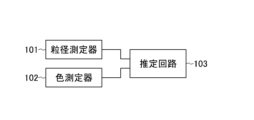
- FIG. 2 is a configuration diagram showing the configuration of the corrosion estimation device according to the embodiment of the present invention.
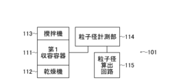
- FIG. 3 is a configuration diagram showing a partial configuration of the corrosion estimation device according to the embodiment of the present invention.
- FIG. 4 is a configuration diagram showing a partial configuration of the corrosion estimation device according to the embodiment of the present invention.
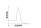
- FIG. 5 is a characteristic diagram showing temporal changes in the corrosion rate estimated from the grain size of soil.
- FIG. 6 is a characteristic diagram showing the relationship between the CIELAB L * value and the corrosion rate magnification.
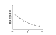
- FIG. 7 is a characteristic diagram showing the relationship between the CIELAB a * value and the corrosion rate magnification.
- FIG. 1 is a flow chart explaining a corrosion estimation method according to an embodiment of the present invention.
- FIG. 2 is a configuration diagram showing the configuration of the corrosion estimation device according to the embodiment of the present invention.
- FIG. 3 is a configuration
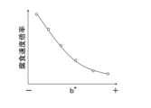
- FIG. 8 is a characteristic diagram showing the relationship between the CIELAB b * value and the corrosion rate magnification.
- FIG. 9 is a characteristic diagram showing temporal changes in the corrosion rate estimated from the grain size and color of soil.
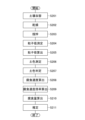
- FIG. 10 is a flow chart explaining in more detail the corrosion estimation method according to the embodiment of the present invention.
- step S101 the particle size of soil is measured (particle size measurement step).
- JIS A 1204:2009 Metal for testing particle size of soil
- a method based on JIS Z 8825:2013 “particle size analysis-laser diffraction/scattering method” can be used.
- a color measurement value relating to the color of the soil is measured (color measurement step).
- color values can be measured as color measurements.
- a standard soil color chart in which the standard soil colors are arranged according to the Munsell systematic classification system can be used.
- a spectrophotometer can be used to measure the color measurement value.
- step S103 the corrosion of the steel material buried in the soil is estimated from the measured particle size and color measurement value (estimation step).
- the corrosion rate is obtained from the measured particle size
- the corrosion rate magnification is obtained from the measured color measurement value
- the corrosion rate is multiplied by the corrosion rate magnification to obtain the corrected corrosion rate
- the corrected corrosion rate is obtained.
- This corrosion estimating device comprises a particle size measuring device 101 that measures the particle size of soil, a color measuring device 102 that measures a color measurement value related to the color of the soil, and from the measured particle size and the measured color measurement value, and an estimation circuit 103 for estimating corrosion of the steel material buried in the soil.
- the color measurer 102 measures color values, for example, as color measurements.
- the estimation circuit 103 obtains the corrosion rate from the particle diameter, obtains the corrosion rate multiplier from the color measurement value, obtains the corrected corrosion rate by multiplying the corrosion rate by the corrosion rate multiplier, and estimates the corrosion of the steel material from the obtained corrected corrosion rate.
- the estimation circuit 103 is computer equipment including a CPU (Central Processing Unit), a memory, and the like.
- the function (estimation step) described above is realized by the CPU operating (executing the program) by the program developed in the memory.
- the estimation circuit 103 can be configured by a programmable logic device (PLD: Programmable Logic Device) such as an FPGA (field-programmable gate array).
- PLD Programmable Logic Device
- FPGA field-programmable gate array
- soil corrosion is a complex system, so the key to estimating soil corrosion is how to extract and analyze the controlling factors related to corrosion from the solid phase that is unique to the soil environment. is the key.
- soil particle size is the most effective environmental factor for estimating information on the liquid phase and gas phase that governs the presence or absence of corrosion for soil corrosion.
- soil color The most important factor in estimating the chemical components in soil is the color of the soil (soil color).
- soil color For example, "soil groups" classified according to the agricultural land soil classification standard are classified by soil color based on soil chemical components that are important for implementing agriculture. For example, black soil, as the name suggests, is black in color and contains organic acids derived from humus. Brown soil, yellow soil, and red soil are classified according to the ratio of iron oxide in the soil, and gley soil, which gives a blue color, is also derived from reduced iron. From these facts, it is possible to estimate the acceleration of corrosion from the chemical components in the soil based on the color of the soil.
- the particle size measuring device 101 includes a first container 111 , a dryer 112 , a stirrer 113 , a particle size measuring section 114 and a particle size calculating circuit 115 .
- the particle size measuring instrument 101 performs a test for measuring the particle size of soil.
- the soil in which the steel material whose corrosion amount is to be estimated is buried is stored in the first container 111.
- the amount of soil to be stored in the first container 111 varies depending on the particle size measurement method described below, but the maximum amount can be about 500 mL.
- the shape of the first container 111 is not limited as long as it is large enough to contain the amount of soil required for measurement.
- a user can arbitrarily determine the material that constitutes the first container 111 .
- the first container 111 is made of a metal material
- the first container 111 contains wet soil
- corrosion reactions with the wet soil occur depending on the metal, degrading the container, and furthermore, corrosion products are mixed into the wet soil. and may affect the soil color measurement described later. Therefore, it is preferable to avoid metallic materials when selecting materials for the first container 111 .
- the first container 111 can be made of heat-resistant polymer resin, glass, or the like.
- soil particle clumps may be formed due to the capillary phenomenon of water trapped in the particle gaps.
- particle size measurement is performed in the presence of soil particle masses, a large proportion of particles larger than the original particle size are detected, making it difficult to obtain the true particle size. In order to prevent this, it is important to remove the water in the interstices between the particles, which is the cause of the lumps of soil particles.
- the dryer 112 dries the contained soil by, for example, applying heat to raise the temperature of the first container 111 . Also, the dryer 112 can reduce the pressure in the first container 111 to perform vacuum drying. Here, when heat is applied, a material that can withstand the temperature set by the user for the first container 111 must be selected.
- the temperature rise in the first storage container 111 it is preferable to limit the temperature rise in the first storage container 111 to an upper limit of 50°C.
- the first container 111 is made of a material that can withstand the reduced pressure.
- the first container 111 is preferably made of glass.
- the drying operation in the dryer 112 ends when the moisture content of the soil contained in the first container 111 reaches 0%. For example, by installing a soil moisture content sensor in the first container 111, the soil moisture content of the first container 111 can be detected.
- the dryer 112 is not limited to the drying method described above, as long as it is a mechanism that realizes a method capable of reducing the moisture content of the soil in the first container 111 to 0%.
- the agitator 113 agitates the soil in the first container 111 whose soil moisture content has become 0% due to drying by the dryer 112 in order to break up the soil particle clumps.
- the stirrer 113 is not limited as long as it is a mechanism capable of dissolving all the soil particle clumps.
- it can be composed of a mechanism for circularly stirring two rod-shaped stirrers.
- a mechanism similar to an automatic stirrer employed in food factories or the like can be employed.
- the particle size measurement unit 114 measures the particle size of the soil in the first container 111 that has been pretreated by the dryer 112 and the stirrer 113 .
- JIS A 1204:2009 “Method for testing particle size of soil” can be used.
- the particle size can be measured according to JIS Z 8825:2013 "Particle Size Analysis - Laser Diffraction/Scattering Method".
- the particle size is calculated using the soil particle sedimentation method using hydrohail. It is possible to calculate the particle size distribution by combining the results of the sieve method for soil particles of 75 ⁇ m or more and the sedimentation method for soil particles of less than 75 ⁇ m. Note that about 500 mL of soil to be accommodated in the first container 111 is required to carry out the soil particle size test method.
- Particle size analysis-laser diffraction/scattering method which is another measurement technology that can measure particle size, irradiates soil particles with laser light, and diffracted/scattered light with different intensities depending on the size of the particles is generated.
- the particle size distribution is calculated by analyzing the light intensity distribution pattern formed from the diffracted/scattered light.
- the amount of soil contained in the first container 111 can be about 50 mL.
- the soil used for the measurement by the particle size measuring unit 114 can be discarded as it is, or can be reused in the color measuring device 102 . When discarding, it is necessary to additionally prepare soil in an amount that enables measurement by the color measuring device 102 . Further, when reused by the color measuring device 102, it is not necessary to prepare an additional amount of soil. The work and the removal of the soil mass with the agitator 113 must be carried out again.
- the particle size measurement result measured by the particle size measurement unit 114 is sent to the particle size calculation circuit 115, and the particle size distribution is derived based on the measurement result.
- the particle size distribution obtained by the particle size calculation circuit 115 is, for example, a graph in which the horizontal axis indicates the particle size and the vertical axis indicates the frequency % of each particle size and the cumulative frequency %.
- a color measuring instrument 102 performs a test for measuring the color of the soil.
- soil is transferred from the first container 111 of the particle size measuring device 101 to the second container 121 .
- the shape and material of the second storage container 121 are not particularly limited as long as the soil color can be measured. However, it is essential that the soil color can be determined from the outside of the first container 111 regardless of which of the method of using a measuring instrument or the visual confirmation by the measurer is selected as the soil color measuring means. Therefore, it is preferable that the container has a shape in which the upper portion is largely open, such as a petri dish, or that the entire surface of the container is made of a transparent material.
- the soil color measurement unit 122 measures the color of the soil in the second container 121, and the soil color determination circuit 123 determines the measured soil color.
- the soil color measurement in the earth color measurement unit 122 for example, a standard earth color chart in which the standard earth colors are arranged according to the Munsell system classification method can be used. Further, a spectrophotometer can be used for earth color measurement in the earth color measurement unit 122 .
- the person who performs the measurement is always the same person in order to reduce the measurement error as much as possible when measuring the soil color for multiple soils. is preferred.
- the measurer who uses the standard soil color chart to measure the soil color completes the measurement by recording the color values of hue, lightness, and saturation described in the standard soil color chart.
- a spectrophotometer is a type of photometer, and can obtain information about a color by measuring the wavelength intensity of each color.
- the second container 121 When a spectrophotometer is used as the soil color measurement unit 122, the second container 121 must be a transparent spectroscopic cell that enables measurement.
- the color information measured and stored is sent to the earth color determination circuit 123 and converted into some color value.
- color values for example, the CIE 1976 (L * a * b * ) color space (CIELAB) developed by the International Commission on Illumination (CIE) can be used.
- CIELAB describes color values as three coordinates: L * representing the lightness of the color, a * representing the location of red and green, and b * representing the location of yellow and blue.
- the values of L * , a * , and b * can be calculated by the earth color determination circuit 123 and used as earth color measurement results.
- the estimation circuit 103 estimates the corrosion amount of the steel buried in the measured soil based on the results obtained by the particle size measuring device 101 and the color measuring device 102 .
- the particle size measurement result (particle size distribution) obtained by the particle size calculation circuit 115 and the soil color measurement result (earth color determination result) obtained by the soil color determination circuit 123 are sent to the memory of the estimation circuit 103 .
- the estimation circuit 103 calculates and outputs a corrosion amount estimation result using each measurement result stored in the memory. From the particle size measurement result (particle size distribution) obtained by the particle size calculation circuit 115 in the particle size measuring device 101, information on the corrosion rate due to soil corrosion is obtained.
- the progress of the corrosion reaction is determined by the wetted area of the metal surface embedded in the soil and the oxygen partial pressure.
- the wetted area depends on the capillary force of water trapped in the interparticle spaces, which can be determined from the interparticle diameter, ie the particle size distribution.
- the oxygen partial pressure is the same, after the interstices between particles are filled with water such as rainwater, the water penetrates deep underground as gravity water and diffuses, and oxygen diffuses from the surface layer to the metal surface. supplied.
- the supplied oxygen dissolves in water and can reach the metal surface as dissolved oxygen.
- the diffusion rate of dissolved oxygen is 10 4 times slower than that of gaseous oxygen, it diffuses through the soil as a gas. The longer the distance, the easier it is to supply the oxygen necessary for the corrosion reaction. That is, in order to lengthen the distance in which gaseous oxygen can diffuse, the water in the soil is interlocked with the permeation diffusion speed, and the water permeation diffusion speed is also determined by the particle size distribution.
- FIG. 5 shows the time change of the corrosion rate estimated from the results of measuring the grain size in soil under various conditions.
- the corrosion rate of steel buried underground exhibits a time-varying behavior as shown in Fig. 5, and the timing at which the corrosion rate increases and the value of the maximum corrosion rate change depending on the particle size distribution. Therefore, the relationship between the particle size distribution and the behavior of the corrosion rate changing over time is investigated in advance, the results are stored in the memory of the estimation circuit 103, and compared with the results obtained by the particle size measuring instrument 101, the corrosion rate can be easily obtained (taken out).
- the corrosion rate can be quantitatively measured using an electrochemical measurement method.
- the measurement by the electrochemical measurement method is repeated until the wet soil dries, and the graph of FIG. 5 can be obtained in advance according to each particle size distribution. Also, if it is desired to save the trouble of acquiring the time-varying behavior of the corrosion rate, only the maximum corrosion rate can be stored in the memory of the estimation circuit 103 .
- FIG. 6 is an example of a graph showing the relationship between the CIELAB L * value and the corrosion rate magnification.
- the corrosion rate multiplier is determined by the value of L * , and the corrosion rate value in FIG. 5 is multiplied by the corrosion rate multiplier to obtain the true corrosion rate in each soil. be able to.
- L * and corrosion rate magnification a graph can be set in which the magnification is set higher as L * is closer to 0, and the relationship between L * and corrosion rate magnification should be investigated in advance. can be done.
- FIG. 7 is an example of a graph showing the relationship between the CIELAB a * value and the corrosion rate magnification.
- the a * value indicates the position of red and green, with a negative a * value indicating green color and a positive a * value indicating red color.
- a lot of iron oxide is contained in the soil showing red color. If there is a lot of iron oxide in the environment as a corrosion product, the corrosion reaction will be slowed down from the viewpoint of chemical equilibrium theory, and the corrosion rate multiplier will be low. Therefore, it is possible to set FIG. 7 so that the corrosion rate magnification is low when the a * value takes a positive value, and the relationship between the a * value and the corrosion rate magnification can be investigated in advance. .
- FIG. 8 is an example of a graph showing the relationship between the CIELAB b * value and the corrosion rate magnification.
- the b * value indicates the position of yellow and blue.
- a negative b * value indicates blue color, and a positive b * value indicates yellow color.
- Blue soil contains a large amount of reduced iron and is rich in electron acceptors necessary for the progress of the corrosion reaction, so it has the characteristic of significantly increasing the corrosion rate. Therefore, it is possible to set FIG. 8 so that the corrosion rate multiplying factor increases when the b * value takes a negative value, and the relationship between the b * value and the corrosion rate multiplying factor can be investigated in advance. .
- the estimating circuit 103 multiplies the change in corrosion rate over time or the maximum corrosion rate obtained from the results obtained from the grain size measuring device 101 by the corrosion rate magnification obtained from the results obtained from the color measuring device 102 to obtain a corrected corrosion rate. Calculate This calculation completes the acquisition of all information about the corrosion rate. Subsequently, the estimation circuit 103 performs estimation calculation of the corrosion amount from the information of the corrosion rate.
- the change in corrosion rate over time is extracted from the results obtained by the particle size measuring device 101, it indicates the change in corrosion rate over time from one rain to the next, so the extracted time change is integrated. By doing so, it is possible to calculate the amount of corrosion that progresses in one rain. Therefore, the rainfall information of the area where the used soil was buried is obtained, and the amount of corrosion that progresses in one rain is added for the number of rains to obtain the amount of corrosion R that progresses in one year.
- D is the amount of corrosion [mm]
- T is the age of the buried metal material [year]
- n is the corrosion evaluation value of the material.
- the value of n is empirically said to be 0.4 to 0.6, an intermediate value of 0.5 can be adopted. It is possible to estimate the amount of corrosion of the buried metal material by introducing an aging value that describes how many years have passed since the buried metal material whose corrosion amount is to be estimated is inserted into T in the formula (1). be.
- FIG. 9 is an example of a graph showing the amount of corrosion and the elapsed years estimated from the results of FIGS. It is an example of a graph representing.
- step S ⁇ b>201 soil is introduced into the corrosion estimating device and stored in the first container 111 of the particle size measuring device 101 .
- step S202 the dryer 112 is operated for the soil accommodated in the first container 111 to dry the soil.
- step S203 the agitator 113 is operated to agitate the dried soil to remove soil clogs.
- step S204 the particle diameter measurement unit 114 is operated to measure the particle diameter.
- step S205 the particle size distribution is determined by the particle size calculation circuit 115 based on the measured particle size.
- step S ⁇ b>206 the color of the soil in the second container 121 is measured by the soil color measurement unit 122 .
- step S207 the soil color determination circuit 123 determines the color of the measured soil.
- step S208 the estimation circuit 103 calculates the corrosion rate of the steel buried in the measured soil based on the results obtained by the particle size measuring device 101.
- step S ⁇ b>209 the estimation circuit 103 calculates the corrosion rate magnification from the result obtained by the color measuring device 102 .
- step S210 the estimation circuit 103 multiplies the corrosion rate value by the corrosion rate multiplier to obtain the corrosion rate (corrected corrosion rate).
- step S211 the estimation circuit 103 estimates the corrosion (corrosion curve) of the metal material buried underground from the obtained corrosion rate.
- the corrosion of steel materials buried in the soil is estimated from the measured particle size and color measurement value, so the corrosion of metal materials buried underground can be easily estimated. become able to.
- the present invention in soil corrosion, which is a complex corrosion system, it is possible to estimate soil corrosion at low cost and simply by estimating soil corrosion from only solid phase information in a small number of tests and in a short time. , the condition-based maintenance of metal structures buried underground becomes possible, and economic efficiency and safety are ensured due to high efficiency.
Landscapes
- Chemical & Material Sciences (AREA)
- Life Sciences & Earth Sciences (AREA)
- Health & Medical Sciences (AREA)
- Physics & Mathematics (AREA)
- Analytical Chemistry (AREA)
- Biochemistry (AREA)
- General Health & Medical Sciences (AREA)
- General Physics & Mathematics (AREA)
- Immunology (AREA)
- Pathology (AREA)
- Dispersion Chemistry (AREA)
- Engineering & Computer Science (AREA)
- Environmental & Geological Engineering (AREA)
- General Life Sciences & Earth Sciences (AREA)
- Geology (AREA)
- Remote Sensing (AREA)
- Food Science & Technology (AREA)
- Medicinal Chemistry (AREA)
- Molecular Biology (AREA)
- Chemical Kinetics & Catalysis (AREA)
- Electrochemistry (AREA)
- Biodiversity & Conservation Biology (AREA)
- Ecology (AREA)
- Environmental Sciences (AREA)
- Testing Resistance To Weather, Investigating Materials By Mechanical Methods (AREA)
Abstract
Description
Claims (6)
- 土壌の粒子径を測定する粒径測定ステップと、
前記土壌の色に関する色測定値を測定する色測定ステップと、
前記粒子径および前記色測定値から、前記土壌に埋設される鋼材の腐食を推定する推定ステップと
を備える腐食推定方法。 - 請求項1記載の腐食推定方法において、
前記推定ステップは、前記粒子径から腐食速度を求め、前記色測定値から腐食速度倍率を求め、前記腐食速度に前記腐食速度倍率を乗じて補正腐食速度を求め、求めた補正腐食速度により前記鋼材の腐食を推定することを特徴とする腐食推定方法。 - 請求項1または2記載の腐食推定方法において、
前記色測定ステップは、前記色測定値として色値を測定することを特徴とする腐食推定方法。 - 土壌の粒子径を測定する粒径測定器と、
前記土壌の色に関する色測定値を測定する色測定器と、
前記粒子径および前記色測定値から、前記土壌に埋設される鋼材の腐食を推定する推定回路と
を備える腐食推定装置。 - 請求項4記載の腐食推定装置において、
前記推定回路は、前記粒子径から腐食速度を求め、前記色測定値から腐食速度倍率を求め、前記腐食速度に前記腐食速度倍率を乗じて補正腐食速度を求め、求めた補正腐食速度により前記鋼材の腐食を推定することを特徴とする腐食推定装置。 - 請求項4または5記載の腐食推定装置において、
前記色測定器は、前記色測定値として色値を測定することを特徴とする腐食推定装置。
Priority Applications (3)
| Application Number | Priority Date | Filing Date | Title |
|---|---|---|---|
| PCT/JP2021/039232 WO2023073751A1 (ja) | 2021-10-25 | 2021-10-25 | 腐食推定方法および装置 |
| US18/690,136 US20250130151A1 (en) | 2021-10-25 | 2021-10-25 | Corrosion estimation method and device |
| JP2023555882A JP7683722B2 (ja) | 2021-10-25 | 2021-10-25 | 腐食推定方法および装置 |
Applications Claiming Priority (1)
| Application Number | Priority Date | Filing Date | Title |
|---|---|---|---|
| PCT/JP2021/039232 WO2023073751A1 (ja) | 2021-10-25 | 2021-10-25 | 腐食推定方法および装置 |
Publications (1)
| Publication Number | Publication Date |
|---|---|
| WO2023073751A1 true WO2023073751A1 (ja) | 2023-05-04 |
Family
ID=86157490
Family Applications (1)
| Application Number | Title | Priority Date | Filing Date |
|---|---|---|---|
| PCT/JP2021/039232 Ceased WO2023073751A1 (ja) | 2021-10-25 | 2021-10-25 | 腐食推定方法および装置 |
Country Status (3)
| Country | Link |
|---|---|
| US (1) | US20250130151A1 (ja) |
| JP (1) | JP7683722B2 (ja) |
| WO (1) | WO2023073751A1 (ja) |
Citations (4)
| Publication number | Priority date | Publication date | Assignee | Title |
|---|---|---|---|---|
| WO2020066715A1 (ja) * | 2018-09-27 | 2020-04-02 | 日本電信電話株式会社 | 腐食性評価装置とその方法 |
| WO2021100193A1 (ja) * | 2019-11-22 | 2021-05-27 | 日本電信電話株式会社 | 腐食速度推定装置とその方法 |
| WO2021100117A1 (ja) * | 2019-11-19 | 2021-05-27 | 日本電信電話株式会社 | 腐食量推定装置および腐食量推定方法 |
| WO2021100196A1 (ja) * | 2019-11-22 | 2021-05-27 | 日本電信電話株式会社 | 予測装置とその方法 |
Family Cites Families (3)
| Publication number | Priority date | Publication date | Assignee | Title |
|---|---|---|---|---|
| JP6850766B2 (ja) * | 2018-05-23 | 2021-03-31 | 日本電信電話株式会社 | 腐食量推定装置および腐食量推定方法 |
| JP7201947B2 (ja) * | 2019-05-20 | 2023-01-11 | 日本電信電話株式会社 | 腐食評価支援装置および腐食評価支援方法 |
| JPWO2023223413A1 (ja) * | 2022-05-17 | 2023-11-23 |
-
2021
- 2021-10-25 JP JP2023555882A patent/JP7683722B2/ja active Active
- 2021-10-25 WO PCT/JP2021/039232 patent/WO2023073751A1/ja not_active Ceased
- 2021-10-25 US US18/690,136 patent/US20250130151A1/en active Pending
Patent Citations (4)
| Publication number | Priority date | Publication date | Assignee | Title |
|---|---|---|---|---|
| WO2020066715A1 (ja) * | 2018-09-27 | 2020-04-02 | 日本電信電話株式会社 | 腐食性評価装置とその方法 |
| WO2021100117A1 (ja) * | 2019-11-19 | 2021-05-27 | 日本電信電話株式会社 | 腐食量推定装置および腐食量推定方法 |
| WO2021100193A1 (ja) * | 2019-11-22 | 2021-05-27 | 日本電信電話株式会社 | 腐食速度推定装置とその方法 |
| WO2021100196A1 (ja) * | 2019-11-22 | 2021-05-27 | 日本電信電話株式会社 | 予測装置とその方法 |
Also Published As
| Publication number | Publication date |
|---|---|
| US20250130151A1 (en) | 2025-04-24 |
| JPWO2023073751A1 (ja) | 2023-05-04 |
| JP7683722B2 (ja) | 2025-05-27 |
Similar Documents
| Publication | Publication Date | Title |
|---|---|---|
| Huang et al. | Ultimate analysis and heating value prediction of straw by near infrared spectroscopy | |
| Ikani et al. | Analytical modelling and electrochemical impedance spectroscopy (EIS) to evaluate influence of corrosion product on solution resistance | |
| Villas-Boas et al. | Laser-induced breakdown spectroscopy to determine soil texture: A fast analytical technique | |
| US20220414486A1 (en) | Predictor and Method | |
| Rifai et al. | Analysis of gold in rock samples using laser-induced breakdown spectroscopy: Matrix and heterogeneity effects | |
| Jadreško et al. | Electrochemical faradaic spectroscopy | |
| Ma et al. | Hyperspectral reflectance for determination of steel rebar corrosion and Cl− concentration | |
| WO2019225664A1 (ja) | 腐食量推定装置および腐食量推定方法 | |
| Yang et al. | Fast determination of oxides content in cement raw meal using NIR-spectroscopy and backward interval PLS with genetic algorithm | |
| CN108918606B (zh) | 介电法测定土壤含水量的土壤原位率定曲线的获取方法 | |
| CN113607611A (zh) | 一种粉体物料混合均匀度的耦合评价方法 | |
| WO2021100193A1 (ja) | 腐食速度推定装置とその方法 | |
| Khuzestani et al. | A non-destructive optical color space sensing system to quantify elemental and organic carbon in atmospheric particulate matter on Teflon and quartz filters | |
| Ding et al. | Spatial variation and controls of soil microbial necromass carbon in a tropical montane rainforest | |
| Yen et al. | Gas adsorption mechanism on 2D materials: the hyperpolarizability evolution analyzed by nonlinear optics | |
| JP7683722B2 (ja) | 腐食推定方法および装置 | |
| Moros et al. | Characterization of estuarine sediments by near infrared diffuse reflectance spectroscopy | |
| JP5399338B2 (ja) | 多孔質材料の緻密さ評価方法および多孔質材料の緻密さ評価システム | |
| KR20200074542A (ko) | 글로우 방전 광학 방출 분광법의 다변량 분석을 이용한 철강 표면 산화철의 정량 분석 방법 | |
| Macha et al. | Development of a methodology to predict atmospheric corrosion severity using corrosion sensor technologies | |
| Hartono et al. | Development of quick test method for soil pH, nitrate, phosphorus, and potassium combining chemicals and phone cellular application | |
| CN106840948B (zh) | 封窖泥质量鉴别方法 | |
| WO2023223413A1 (ja) | 腐食推定装置および方法 | |
| JP5569738B2 (ja) | 多孔質材料の含液状態評価方法および多孔質材料の含液状態評価システム | |
| CN116124755A (zh) | 一种基于拉曼光谱的海相泥页岩成熟度测试方法 |
Legal Events
| Date | Code | Title | Description |
|---|---|---|---|
| 121 | Ep: the epo has been informed by wipo that ep was designated in this application |
Ref document number: 21962302 Country of ref document: EP Kind code of ref document: A1 |
|
| WWE | Wipo information: entry into national phase |
Ref document number: 2023555882 Country of ref document: JP |
|
| WWE | Wipo information: entry into national phase |
Ref document number: 18690136 Country of ref document: US |
|
| NENP | Non-entry into the national phase |
Ref country code: DE |
|
| 122 | Ep: pct application non-entry in european phase |
Ref document number: 21962302 Country of ref document: EP Kind code of ref document: A1 |
|
| WWP | Wipo information: published in national office |
Ref document number: 18690136 Country of ref document: US |