WO2023068337A1 - 反力付与装置 - Google Patents
反力付与装置 Download PDFInfo
- Publication number
- WO2023068337A1 WO2023068337A1 PCT/JP2022/039168 JP2022039168W WO2023068337A1 WO 2023068337 A1 WO2023068337 A1 WO 2023068337A1 JP 2022039168 W JP2022039168 W JP 2022039168W WO 2023068337 A1 WO2023068337 A1 WO 2023068337A1
- Authority
- WO
- WIPO (PCT)
- Prior art keywords
- pedal
- reaction force
- actuator
- housing
- applying device
- Prior art date
- Legal status (The legal status is an assumption and is not a legal conclusion. Google has not performed a legal analysis and makes no representation as to the accuracy of the status listed.)
- Ceased
Links
Images


Classifications
-
- B—PERFORMING OPERATIONS; TRANSPORTING
- B60—VEHICLES IN GENERAL
- B60K—ARRANGEMENT OR MOUNTING OF PROPULSION UNITS OR OF TRANSMISSIONS IN VEHICLES; ARRANGEMENT OR MOUNTING OF PLURAL DIVERSE PRIME-MOVERS IN VEHICLES; AUXILIARY DRIVES FOR VEHICLES; INSTRUMENTATION OR DASHBOARDS FOR VEHICLES; ARRANGEMENTS IN CONNECTION WITH COOLING, AIR INTAKE, GAS EXHAUST OR FUEL SUPPLY OF PROPULSION UNITS IN VEHICLES
- B60K26/00—Arrangement or mounting of propulsion-unit control devices in vehicles
- B60K26/02—Arrangement or mounting of propulsion-unit control devices in vehicles of initiating means or elements
-
- B—PERFORMING OPERATIONS; TRANSPORTING
- B60—VEHICLES IN GENERAL
- B60K—ARRANGEMENT OR MOUNTING OF PROPULSION UNITS OR OF TRANSMISSIONS IN VEHICLES; ARRANGEMENT OR MOUNTING OF PLURAL DIVERSE PRIME-MOVERS IN VEHICLES; AUXILIARY DRIVES FOR VEHICLES; INSTRUMENTATION OR DASHBOARDS FOR VEHICLES; ARRANGEMENTS IN CONNECTION WITH COOLING, AIR INTAKE, GAS EXHAUST OR FUEL SUPPLY OF PROPULSION UNITS IN VEHICLES
- B60K26/00—Arrangement or mounting of propulsion-unit control devices in vehicles
- B60K26/02—Arrangement or mounting of propulsion-unit control devices in vehicles of initiating means or elements
- B60K26/021—Arrangement or mounting of propulsion-unit control devices in vehicles of initiating means or elements with means for providing feel, e.g. by changing pedal force characteristics
-
- F—MECHANICAL ENGINEERING; LIGHTING; HEATING; WEAPONS; BLASTING
- F02—COMBUSTION ENGINES; HOT-GAS OR COMBUSTION-PRODUCT ENGINE PLANTS
- F02D—CONTROLLING COMBUSTION ENGINES
- F02D11/00—Arrangements for, or adaptations to, non-automatic engine control initiation means, e.g. operator initiated
- F02D11/02—Arrangements for, or adaptations to, non-automatic engine control initiation means, e.g. operator initiated characterised by hand, foot, or like operator controlled initiation means
-
- G—PHYSICS
- G05—CONTROLLING; REGULATING
- G05G—CONTROL DEVICES OR SYSTEMS INSOFAR AS CHARACTERISED BY MECHANICAL FEATURES ONLY
- G05G5/00—Means for preventing, limiting or returning the movements of parts of a control mechanism, e.g. locking controlling member
- G05G5/03—Means for enhancing the operator's awareness of arrival of the controlling member at a command or datum position; Providing feel, e.g. means for creating a counterforce
-
- G—PHYSICS
- G05—CONTROLLING; REGULATING
- G05G—CONTROL DEVICES OR SYSTEMS INSOFAR AS CHARACTERISED BY MECHANICAL FEATURES ONLY
- G05G1/00—Controlling members, e.g. knobs or handles; Assemblies or arrangements thereof; Indicating position of controlling members
- G05G1/30—Controlling members actuated by foot
- G05G1/44—Controlling members actuated by foot pivoting
Definitions
- the present disclosure relates to a reaction force application device.
- the reaction force applying device capable of applying a reaction force against a driver's stepping force to a pedal of an accelerator device having a pedal to be stepped on by the driver.
- the reaction force application device disclosed in Patent Document 1 includes a lever that abuts on an arm that rotates together with a pedal of an accelerator device and that can apply reaction force to the pedal in response to a driver's stepping force.
- the reaction force application device disclosed in Patent Document 1 is attached to the vehicle at a position a predetermined distance away from the accelerator device. That is, the reaction force applying device and the accelerator device are attached to different positions on the floor of the vehicle. Therefore, there is a possibility that the contact point deviation between the lever of the reaction force applying device and the arm of the accelerator device becomes large. As a result, the amount of deviation of the reaction force from the target reaction force becomes large, and there is a possibility that the reaction force of the danger notification, the fuel consumption improvement notification, or the like to the driver may deteriorate the feeling of the driver's notification.
- An object of the present disclosure is to provide a reaction force application device capable of suppressing an increase in the amount of reaction force deviation from a target reaction force.
- the present disclosure is capable of imparting a reaction force to a pedal of an accelerator device that includes a pedal that is stepped on by a driver and a pedal housing that rotatably supports the pedal and can be attached to a vehicle.
- a reaction force applying device includes an actuator housing, an actuator, a lever, a connected portion, and a connecting portion.
- vehicle mountable includes not only direct mountability to the vehicle, but also indirect mountability to the vehicle via other members (the same applies hereinafter).
- the actuator housing can be attached to the vehicle.
- the actuator is provided in the actuator housing.
- the lever is provided in the actuator housing, is rotated by a driving force from the actuator, contacts the pedal or an arm that rotates together with the pedal, and can apply a reaction force to the pedal in response to the driver's stepping force.
- the connected part is provided on the pedal housing.
- the connecting portion is provided on the actuator housing and connected to the connected portion.
- the connected portion provided on the pedal housing of the accelerator device and the connecting portion provided on the actuator housing of the reaction force applying device are connected. Therefore, it is possible to reduce variations in the relative positions of the pedal housing and the actuator housing during attachment to the vehicle. As a result, it is possible to reduce the deviation of the point of contact between the lever of the reaction force applying device and the pedal or arm of the accelerator device. Therefore, it is possible to reduce the amount of deviation of the reaction force from the target reaction force. Therefore, it is possible to suppress deterioration of the driver's notification feeling due to the reaction force.
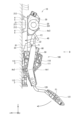
- FIG. 1 is a diagram showing a reaction force applying device of the first embodiment and an accelerator device to which it is applied
- FIG. 2 is a view of FIG. 1 viewed from the direction of arrow II
- FIG. 3 is a schematic diagram showing the connection part and the connected part of the reaction force applying device of the first embodiment
- FIG. 4 is a cross-sectional view taken along line IV-IV of FIG.
- FIG. 5 is a schematic diagram showing part of the reaction force applying device of the first embodiment
- FIG. 6 is a schematic diagram showing the connection part and the connected part of the reaction force applying device of the second embodiment
- FIG. 1 is a diagram showing a reaction force applying device of the first embodiment and an accelerator device to which it is applied
- FIG. 2 is a view of FIG. 1 viewed from the direction of arrow II
- FIG. 3 is a schematic diagram showing the connection part and the connected part of the reaction force applying device of the first embodiment
- FIG. 4 is a cross-sectional view taken along line IV-IV of FIG.
- FIG. 7 is a cross-sectional view taken along line VII-VII of FIG.
- FIG. 8 is a schematic diagram showing the connection part and the connected part of the reaction force applying device of the third embodiment
- 9 is a cross-sectional view taken along line IX-IX of FIG. 8.
- reaction force application device according to a plurality of embodiments and an accelerator device to which it is applied will be described below with reference to the drawings.
- symbol is attached
- FIGS. 1-10 A reaction force application device according to a first embodiment and an accelerator device to which it is applied are shown in FIGS.
- the accelerator device 100 is mounted on the vehicle 1 and used to detect the accelerator opening corresponding to the rotation angle of the pedal 120 depressed by the driver and control the running state of the vehicle 1 .
- the accelerator device 100 employs an accelerator-by-wire system and is not mechanically connected to the throttle device of the vehicle 1 .
- Accelerator device 100 transmits information about the accelerator opening corresponding to the rotation angle of pedal 120 to an electronic control unit (hereinafter referred to as "ECU") not shown.
- the ECU controls the throttle device based on the accelerator opening transmitted from the accelerator device 100 . Thereby, the running state of the vehicle 1 is controlled.
- the reaction force application device 10 is mounted on the vehicle 1 together with the accelerator device 100, and can apply a reaction force F2 to the pedal 120 of the accelerator device 100 against the driver's stepping force F1.
- the reaction force applying device 10 can notify the driver of danger, fuel efficiency improvement, and the like.
- the reaction force applying device 10 restricts the rotation of the pedal 120 so that the pedal 120 can be used as a footrest.
- the accelerator device 100 includes a pedal housing 110, pedals 120 and the like.
- the pedal housing 110 has a housing body 111 and a housing mounting portion 112 .
- the housing main body 111 forms a space in which components can be accommodated.
- the housing attachment portion 112 is formed integrally with the housing body 111 so as to protrude from the housing body 111 . In this embodiment, for example, three housing attachment portions 112 are formed (see FIG. 2).
- a bolt hole 113 is formed in the housing attachment portion 112 .
- the pedal housing 110 is attached to the floor panel 2 by, for example, inserting the attachment bolt 3 through the bolt hole 113 and screwing it into the floor panel 2 of the vehicle 1 and fixing the housing attachment portion 112 to the floor panel 2 .
- the x-axis indicates the traveling direction of the vehicle 1
- the y-axis indicates the vehicle width direction
- the z-axis indicates the vertically upward direction.
- “upper” or “upper” means the upper side or the upper side when the accelerator device 100 or the reaction force application device 10 is attached to the vehicle 1 .
- the floor panel 2 has a wall surface 7 parallel to the yz plane.
- One end of the pedal 120 is rotatably supported by the housing body 111 of the pedal housing 110 so as to rotate around the rotation axis Ax1.
- the other end of the pedal 120 is provided with a pad 121 that is stepped on by the driver.
- an accelerator opening sensor (not shown) is provided on the rotation axis Ax1.
- the accelerator opening sensor detects the accelerator opening corresponding to the rotation angle of the pedal 120 rotated by the driver's stepping operation, and transmits the detected accelerator opening to the ECU.
- the rotation axis Ax1 is set to be orthogonal to the z-axis and the x-axis and parallel to the y-axis.
- a pedal biasing member (not shown) is provided inside the housing body 111 of the pedal housing 110 .
- the pedal 120 is urged in the accelerator closing direction by the pedal urging member.
- the pedal housing 110 has a stopper that restricts rotation of the pedal 120 in the accelerator closing direction and a stopper that restricts rotation in the accelerator opening direction.
- the pedal 120 is rotatable within a range of contact with both stoppers.
- FIG. 1 shows a state in which the pedal 120 is in contact with a stopper in the accelerator closing direction, that is, a state in which the accelerator is fully closed.
- the reaction force applying device 10 includes an actuator housing 20, an actuator 30, a lever 40, a connected portion 61, and a connecting portion 71.
- the actuator housing 20 can be attached to the vehicle 1.
- Actuator 30 is provided in actuator housing 20 .
- the lever 40 is provided in the actuator housing 20, is rotated by the driving force from the actuator 30, contacts the arm 50 that rotates together with the pedal 120, and is capable of applying a reaction force to the pedal 120 against the driver's stepping force.
- the actuator housing 20 has a housing main body 201, a pedestal portion 21, and an actuator-side extending portion 22.
- the housing main body 201 forms a space inside to accommodate the actuator 30 and the like.
- the pedestal 21 has a pedestal body 211 and pedestal legs 212 .
- the pedestal main body 211 is formed in a plate shape integrally with the housing main body 201 .
- a total of two pedestal legs 212 are provided, one on each end of the pedestal main body 211 in the plate surface direction (the z-axis direction in FIG. 1).
- the pedestal legs 212 are formed integrally with the pedestal main body 211 so as to extend obliquely from the pedestal main body 211 in the plate thickness direction.
- the actuator housing 20 attaches the pedestal leg portion 212 of the pedestal portion 21 to the wall surface 7 of the floor panel 2 by, for example, a vehicle body side bolt 4 provided on the floor panel 2 of the vehicle 1 and a nut 5 screwed onto the vehicle body side bolt 4 . It is attached to the floor panel 2 by fixing. The attachment of the reaction force applying device 10 including the actuator housing 20 to the vehicle 1 will be described later.
- the actuator-side extending portion 22 is formed integrally with the base portion main body 211 of the base portion 21 so as to extend downward from the base portion main body 211 .
- the actuator-side extending portion 22 is formed, for example, in a substantially L-shaped plate shape so that the end opposite to the base portion main body 211 is bent (see FIG. 2).
- the actuator 30 is, for example, an electric motor, and is housed inside the housing body 201 of the actuator housing 20 .
- the actuator 30 can output torque as a driving force by energization.
- the ECU can control energization of the actuator 30 and control the operation of the actuator 30 .
- a reduction gear (not shown) comprising a plurality of gears is provided in the housing body 201 .
- the speed reducer can reduce the torque of the actuator 30 and output it.
- One end of the lever 40 is rotatably supported by the actuator housing 20 so as to rotate around the rotation axis Ax3.
- One end of the lever 40 is connected to a speed reducer inside the housing body 201 .
- the lever 40 rotates around the rotation axis Ax3 by driving force from the actuator 30 output from the speed reducer.
- the accelerator device 100 is provided with an arm 50 .
- the arm 50 is formed in the shape of a bending rod and attached to the pedal 120 so that one end thereof is fixed to the pedal 120 .
- Arm 50 is thereby rotatable together with pedal 120 . Therefore, the rotation axis Ax2 of the arm 50 coincides with the rotation axis Ax1 of the pedal 120. As shown in FIG.
- the other end of the lever 40 can contact the other end of the arm 50, that is, the end opposite to the pedal 120.
- the lever 40 is rotated by the driving force from the actuator 30, contacts the other end of the arm 50 that rotates together with the pedal 120, and applies a reaction force F2 to the arm 50 against the stepping force F1 of the driver.
- a reaction force F2 can be applied to the pedal 120 via .
- the connected portion 61 is provided on the pedal housing 110 .
- the connecting portion 71 is provided on the actuator housing 20 and connected to the connected portion 61 .
- two connected portions 61 are provided.
- Two connecting portions 71 are provided.
- the pedal housing 110 is provided with a pedal-side extending portion 23 .
- the pedal-side extending portion 23 is formed integrally with the housing body 111 of the pedal housing 110 so as to extend upward from the housing body 111 .
- the pedal-side extending portion 23 is formed in, for example, a rectangular plate shape (see FIGS. 1 and 2).
- the pedal-side extending portion 23 is formed so as to be able to come into contact with the end portion of the actuator-side extending portion 22 opposite to the base portion 21 .
- the connected portions 61 are formed at two locations on the pedal-side extending portion 23, that is, two.
- Two connection portions 71 are formed at the end of the actuator-side extension portion 22 opposite to the base portion 21 , that is, two connection portions 71 are formed.
- the two connection portions 71 are connected by coming into contact with the two connected portions 61 (see FIGS. 3 and 4).
- This embodiment further includes a bolt 80 that fastens the connected portion 61 and the connecting portion 71 .
- the bolt 80 has a bolt shaft portion 81 and a bolt head portion 82, as shown in FIG.
- the bolt shaft portion 81 is formed in a bar shape, and has a male screw groove formed in its outer peripheral wall.
- the bolt head portion 82 is provided integrally with the bolt shaft portion 81 at one end portion of the bolt shaft portion 81 .
- the outer diameter of the bolt head 82 is larger than the outer diameter of the bolt shank 81 .
- a bolt hole portion 221 that penetrates the actuator-side extension portion 22 in the plate thickness direction is formed at a position corresponding to the connection portion 71 of the actuator-side extension portion 22 . That is, the periphery of the bolt hole portion 221 of the actuator-side extending portion 22 corresponds to the connecting portion 71 .
- a bolt hole portion 231 is formed at a position corresponding to the connected portion 61 of the pedal-side extending portion 23 . That is, the periphery of the bolt hole portion 231 of the pedal-side extending portion 23 corresponds to the connected portion 61 .
- a female screw groove is formed in the inner peripheral wall of the bolt hole portion 231 .
- the bolt shaft portion 81 passes through the bolt hole portion 221 and is screwed into the bolt hole portion 231, and the bolt head portion 82 is locked to the actuator-side extending portion 22, thereby connecting the connected portion 61 and the connecting portion 71 to each other.
- the connected portion 61 and the connecting portion 71 are connected, and the connected portion 61 and the connecting portion 71 are fastened with bolts 80 to define the relative position between the pedal housing 110 and the actuator housing 20 .
- the accelerator device 100 is attached to the vehicle 1 by fixing the pedal housing 110 to the floor panel 2 with the attachment bolts 3 . After that, the accelerator device 100 and the reaction force application device 10 are assembled. Specifically, the connected portion 61 on the accelerator device 100 side and the connecting portion 71 on the reaction force applying device 10 side are connected, and the connected portion 61 and the connecting portion 71 are fastened with the bolt 80 .
- the reaction force applying device 10 is attached to the vehicle 1 by fixing the actuator housing 20 to the floor panel 2 .
- the two vehicle body side bolts 4 are respectively passed through the two mounting holes 213 formed in the pedestal leg part 212 of the actuator housing 20, and the nut 5 is screwed onto the vehicle body side bolt 4 to form the pedestal.
- the reaction force application device 10 is attached to the vehicle 1 (see FIG. 5).
- the inner diameter of the mounting hole portion 213 is larger than the outer diameter of the vehicle body side bolt 4 , the inner diameter of the bolt hole 113 formed in the housing mounting portion 112 of the pedal housing 110 and the threaded portion of the mounting bolt 3 .
- the sum of the difference in diameter, the variation in the positions of the bolt hole 113, the connected portion 61, and the bolt hole portion 231, and the variation in the positions of the connection portion 71, the bolt hole portion 221, and the mounting hole portion 213 is large. Therefore, the actuator housing 20 can absorb the tolerance of each part, and the attachment of the accelerator device 100 and the reaction force applying device 10 to the vehicle 1 and the assembly of the accelerator device 100 and the reaction force applying device 10 are facilitated.
- the connected portion 61 is provided in the pedal housing 110 in this embodiment.
- the connecting portion 71 is provided on the actuator housing 20 and connected to the connected portion 61 .
- the connected portion 61 provided on the pedal housing 110 of the accelerator device 100 and the connecting portion 71 provided on the actuator housing 20 of the reaction force applying device 10 are connected. Therefore, in mounting to the vehicle 1, variations in the relative positions of the pedal housing 110 and the actuator housing 20 can be reduced. As a result, the contact point deviation between the lever 40 of the reaction force applying device 10 and the arm 50 of the accelerator device 100 can be reduced. Therefore, it is possible to reduce the amount of deviation of the reaction force from the target reaction force. Therefore, it is possible to suppress deterioration of the driver's notification feeling due to the reaction force.
- two connected portions 61 are provided.
- Two connecting portions 71 are provided. Therefore, relative rotation between the pedal housing 110 and the actuator housing 20 can be suppressed, and variations in the relative positions of the two can be further reduced.
- this embodiment further includes a bolt 80 that fastens the connected portion 61 and the connecting portion 71 . Therefore, even after the accelerator device 100 and the reaction force applying device 10 are assembled, the connection between the connected portion 61 and the connecting portion 71 is maintained, and variations in the relative positions of the pedal housing 110 and the actuator housing 20 are prevented over a long period of time. can be reduced.
- (Second embodiment) 6 and 7 show part of the reaction force applying device and accelerator device according to the second embodiment.
- the second embodiment differs from the first embodiment in the configuration of the connected portion and the connecting portion.
- the actuator-side extending portion 22 is formed with a press-fitting hole portion 222 instead of the bolt hole portion 221 .
- the press-fitting hole portion 222 is formed in a rectangular shape so as to penetrate the actuator-side extending portion 22 in the plate thickness direction at the end portion of the actuator-side extending portion 22 opposite to the pedestal portion 21 .
- a connecting portion 72 is formed on the inner wall of the press-fitting hole portion 222 and around the press-fitting hole portion 222 . That is, the inner wall of the press-fitting hole portion 222 and the periphery of the press-fitting hole portion 222 in the actuator-side extending portion 22 correspond to the connecting portion 72 .
- a connected portion 62 is formed in the pedal-side extending portion 23 instead of the bolt hole portion 231 .
- the connected portion 62 is formed to protrude in a rectangular columnar shape in the plate thickness direction from the surface of the pedal-side extending portion 23 on the side of the actuator-side extending portion 22 .
- the connecting portion 72 has a rectangular cross-sectional shape by a plane perpendicular to the plate thickness direction of the actuator-side extending portion 22, that is, a non-perfect circular shape.
- the connected portion 62 has a rectangular cross-sectional shape by a plane perpendicular to the plate thickness direction of the pedal-side extending portion 23, that is, a non-circular shape.
- the connected portion 62 and the connecting portion 72 are connected by press fitting.
- the connected portion 62 is press-fitted into the press-fitting hole portion 222 , that is, the connecting portion 72 .
- the connection between the connected portion 62 and the connecting portion 72 is completed, and the assembly of the accelerator device 100 and the reaction force applying device 10 is completed.
- the cross-sectional shape of the connected portion 62 is a non-perfect circular shape.
- the cross-sectional shape of the connecting portion 72 is a non-perfect circular shape. Therefore, relative rotation between the pedal housing 110 and the actuator housing 20 can be suppressed, and variations in the relative positions of the two can be further reduced.
- the connected portion 62 and the connecting portion 72 are connected by press fitting. Therefore, the connected portion 62 and the connecting portion 72 can be easily connected, and the connection between the connected portion 62 and the connecting portion 72 can be maintained even after the accelerator device 100 and the reaction force applying device 10 are assembled, and the pedal Variation in the relative positions of the housing 110 and the actuator housing 20 can be reduced over a long period of time.
- (Third embodiment) 8 and 9 show part of the reaction force applying device and accelerator device according to the third embodiment.
- the third embodiment differs from the second embodiment in the configuration of the connected portion and the connecting portion.
- a snap-fit hole portion 223 is formed in the actuator-side extension portion 22 instead of the press-fit hole portion 222 .
- the snap-fit hole portion 223 is formed in a rectangular shape so as to penetrate the actuator-side extending portion 22 in the plate thickness direction at the end portion of the actuator-side extending portion 22 opposite to the pedestal portion 21 .
- a connecting portion 73 is formed on the inner wall of the snap-fit hole portion 223 and around the snap-fit hole portion 223 . That is, the inner wall of the snap-fit hole portion 223 and the periphery of the snap-fit hole portion 223 in the actuator-side extending portion 22 correspond to the connecting portion 73 .
- a connected portion 63 is formed in place of the connected portion 62 on the pedal-side extending portion 23 .
- the connected portion 63 has a connected portion main body 631 and an engaging portion 632 .
- the connected portion main body 631 is formed to protrude in a rectangular columnar shape in the plate thickness direction from the surface of the pedal-side extension portion 23 on the actuator-side extension portion 22 side.
- Two connected portion main bodies 631 are formed in the pedal-side extending portion 23 .
- the connected portion main body 631 is inserted through the snap-fit hole portion 223 so that the end opposite to the pedal-side extending portion 23 protrudes from the actuator-side extending portion 22 .
- the size d1 of the snap fit hole portion 223 in the z-axis direction is substantially the same as the size d2 of the connected portion main body 631 in the z-axis direction (see FIG. 8).
- the size d3 of the snap fit hole portion 223 in the y-axis direction is larger than the size d4 between the outer walls of the two connected portion main bodies 631 that do not face each other in the y-axis direction (see FIG. 9).
- the engaging portion 632 is formed integrally with the connected portion main bodies 631 so as to protrude in the y-axis direction from the ends of the two connected portion main bodies 631 on the side opposite to the pedal-side extending portion 23 .
- the engaging portion 632 has an inclined surface 633 and an engaging surface 634 .
- the inclined surface 633 is formed in a rectangular planar shape so as to be inclined with respect to the xz plane.
- the engaging surface 634 is formed in a rectangular planar shape so as to be parallel to the yz plane.
- One end of the inclined surface 633 in the x-axis direction is connected to the connected portion body 631 , and the other end of the inclined surface 633 in the x-axis direction is connected to the engaging surface 634 .
- One end of the engaging surface 634 in the y-axis direction is connected to the inclined surface 633, and the other end of the engaging surface 634 in the y-axis direction is connected to the connected portion main body 631 (see FIG. 9
- the connecting portion 73 has a rectangular cross-sectional shape by a plane perpendicular to the plate thickness direction of the actuator-side extending portion 22, that is, a non-perfect circular shape.
- the connected portion 63 has a rectangular cross-sectional shape by a plane perpendicular to the plate thickness direction of the pedal-side extending portion 23, that is, a non-circular shape.
- the connected portion 63 and the connecting portion 73 are connected by snap-fitting.
- the connected portion 63 is inserted into the snap fit hole portion 223 , that is, the connecting portion 73 .
- the connected portion 63 has two inclined surfaces 633 that slide on the inner wall of the snap-fit hole portion 223, and the ends of the two connected portion main bodies 631 on the side opposite to the pedal-side extending portion 23 extend along the y-axis. Deform to move closer to each other in the direction.
- the actuator-side extending portion 22 and the pedal-side extending portion 23 come into contact with each other, the deformation of the two connected portion main bodies 631 is restored, and the engaging surface 634 of the actuator-side extending portion 22 is opposite to the pedal-side extending portion 23 .
- connection portion 73 It engages with the periphery of the snap fit hole portion 223 of the side surface, that is, the connection portion 73 . As a result, the connection between the connected portion 63 and the connecting portion 73 is completed, and the assembly of the accelerator device 100 and the reaction force applying device 10 is completed.
- the cross-sectional shape of the connected portion 63 is a non-perfect circular shape.
- the cross-sectional shape of the connecting portion 73 is a non-perfect circular shape. Therefore, as in the second embodiment, the relative rotation between the pedal housing 110 and the actuator housing 20 can be suppressed, and variations in the relative positions of the two can be further reduced.
- the connected portion 63 and the connecting portion 73 are connected by snap-fitting. Therefore, the connected portion 63 and the connecting portion 73 can be easily and reliably connected, and the connection between the connected portion 63 and the connecting portion 73 can be maintained even after the accelerator device 100 and the reaction force applying device 10 are assembled. , variations in the relative positions of the pedal housing 110 and the actuator housing 20 can be reduced over a long period of time.
- the lever 40 contacts the arm 50 that rotates together with the pedal 120 to apply a reaction force to the pedal 120 .
- the lever 40 may directly contact the pedal 120 to apply a reaction force to the pedal 120 without providing the pedal 120 with the arm 50 .
- the second embodiment shows an example in which the connecting part and the connecting part are connected by press-fitting
- the third embodiment shows an example in which the connecting part and the connecting part are connected by snap-fitting
- the connected portion and the connecting portion may be connected by press-fitting and snap-fitting.
- the cross-sectional shape of the connected portion and the connecting portion may be a non-perfect circular shape such as an elliptical shape, an elliptical shape, or a polygonal shape other than a rectangle.
- the wall surface of the floor panel of the vehicle to which the reaction force applying device and the accelerator device are attached may not be parallel to the yz plane. That is, the wall surface of the floor panel may be formed at any angle with respect to the vehicle.
Landscapes
- Engineering & Computer Science (AREA)
- Chemical & Material Sciences (AREA)
- Combustion & Propulsion (AREA)
- Mechanical Engineering (AREA)
- Transportation (AREA)
- Physics & Mathematics (AREA)
- General Physics & Mathematics (AREA)
- Automation & Control Theory (AREA)
- General Engineering & Computer Science (AREA)
- Auxiliary Drives, Propulsion Controls, And Safety Devices (AREA)
- Mechanical Control Devices (AREA)
- Control Of Throttle Valves Provided In The Intake System Or In The Exhaust System (AREA)
Priority Applications (3)
| Application Number | Priority Date | Filing Date | Title |
|---|---|---|---|
| CN202280070212.XA CN118119521A (zh) | 2021-10-21 | 2022-10-20 | 反作用力赋予装置 |
| DE112022005050.0T DE112022005050T5 (de) | 2021-10-21 | 2022-10-20 | Reaktionskraft-Beaufschlagungsvorrichtung |
| US18/637,536 US12384243B2 (en) | 2021-10-21 | 2024-04-17 | Reaction force applying device |
Applications Claiming Priority (2)
| Application Number | Priority Date | Filing Date | Title |
|---|---|---|---|
| JP2021-172599 | 2021-10-21 | ||
| JP2021172599A JP7694331B2 (ja) | 2021-10-21 | 2021-10-21 | 反力付与装置 |
Related Child Applications (1)
| Application Number | Title | Priority Date | Filing Date |
|---|---|---|---|
| US18/637,536 Continuation US12384243B2 (en) | 2021-10-21 | 2024-04-17 | Reaction force applying device |
Publications (1)
| Publication Number | Publication Date |
|---|---|
| WO2023068337A1 true WO2023068337A1 (ja) | 2023-04-27 |
Family
ID=86058345
Family Applications (1)
| Application Number | Title | Priority Date | Filing Date |
|---|---|---|---|
| PCT/JP2022/039168 Ceased WO2023068337A1 (ja) | 2021-10-21 | 2022-10-20 | 反力付与装置 |
Country Status (5)
| Country | Link |
|---|---|
| US (1) | US12384243B2 (https=) |
| JP (1) | JP7694331B2 (https=) |
| CN (1) | CN118119521A (https=) |
| DE (1) | DE112022005050T5 (https=) |
| WO (1) | WO2023068337A1 (https=) |
Citations (5)
| Publication number | Priority date | Publication date | Assignee | Title |
|---|---|---|---|---|
| JP2001310648A (ja) * | 2000-04-28 | 2001-11-06 | Oiles Ind Co Ltd | 自動車のアクセルペダル装置 |
| JP2010111379A (ja) * | 2008-10-06 | 2010-05-20 | Mikuni Corp | アクセルペダル装置 |
| WO2012029503A1 (ja) * | 2010-08-31 | 2012-03-08 | 本田技研工業株式会社 | 反力ペダル装置 |
| JP2015119566A (ja) * | 2013-12-18 | 2015-06-25 | 株式会社ミツバ | アクチュエータ |
| JP2019508864A (ja) * | 2016-03-15 | 2019-03-28 | スリーエム イノベイティブ プロパティズ カンパニー | 回転可能なコネクタアセンブリ |
Family Cites Families (16)
| Publication number | Priority date | Publication date | Assignee | Title |
|---|---|---|---|---|
| JPS5636522U (https=) | 1979-08-29 | 1981-04-08 | ||
| DE102009021585A1 (de) * | 2009-05-15 | 2010-12-02 | Conti Temic Microelectronic Gmbh | Kompaktes Pedalsystem für ein Kraftfahrzeug |
| JP5344314B2 (ja) | 2010-10-08 | 2013-11-20 | 株式会社デンソー | ペダル装置 |
| JP5740175B2 (ja) * | 2011-02-21 | 2015-06-24 | 株式会社ミクニ | アクセルペダル装置 |
| CA2890639C (en) | 2013-10-04 | 2015-11-17 | Honda Motor Co., Ltd. | Vehicle accelerator pedal apparatus |
| CN107878195A (zh) * | 2013-10-08 | 2018-04-06 | 本田制锁有限公司 | 反力发生装置 |
| JP6033197B2 (ja) * | 2013-10-08 | 2016-11-30 | 株式会社ホンダロック | 反力出力装置 |
| JP6361529B2 (ja) * | 2015-03-04 | 2018-07-25 | 株式会社ホンダロック | 反力出力装置 |
| JP6866331B2 (ja) | 2018-07-10 | 2021-04-28 | 豊田鉄工株式会社 | 車両用操作ペダル装置 |
| JP7419824B2 (ja) * | 2020-01-13 | 2024-01-23 | 株式会社デンソー | 車両用ブレーキ装置 |
| WO2021172599A1 (ko) | 2020-02-24 | 2021-09-02 | 박용덕 | 착탈식 가정용 블랙박스 |
| JP2023062539A (ja) * | 2021-10-21 | 2023-05-08 | 株式会社デンソー | 反力付与装置 |
| JP7533419B2 (ja) * | 2021-10-21 | 2024-08-14 | 株式会社デンソー | 反力付与装置 |
| JP2024052372A (ja) * | 2022-09-30 | 2024-04-11 | 株式会社デンソー | 反力付与装置 |
| JP7768083B2 (ja) * | 2022-09-30 | 2025-11-12 | 株式会社デンソー | 反力付与装置 |
| JP2024052353A (ja) * | 2022-09-30 | 2024-04-11 | 株式会社デンソー | 反力付与装置 |
-
2021
- 2021-10-21 JP JP2021172599A patent/JP7694331B2/ja active Active
-
2022
- 2022-10-20 DE DE112022005050.0T patent/DE112022005050T5/de active Pending
- 2022-10-20 WO PCT/JP2022/039168 patent/WO2023068337A1/ja not_active Ceased
- 2022-10-20 CN CN202280070212.XA patent/CN118119521A/zh active Pending
-
2024
- 2024-04-17 US US18/637,536 patent/US12384243B2/en active Active
Patent Citations (5)
| Publication number | Priority date | Publication date | Assignee | Title |
|---|---|---|---|---|
| JP2001310648A (ja) * | 2000-04-28 | 2001-11-06 | Oiles Ind Co Ltd | 自動車のアクセルペダル装置 |
| JP2010111379A (ja) * | 2008-10-06 | 2010-05-20 | Mikuni Corp | アクセルペダル装置 |
| WO2012029503A1 (ja) * | 2010-08-31 | 2012-03-08 | 本田技研工業株式会社 | 反力ペダル装置 |
| JP2015119566A (ja) * | 2013-12-18 | 2015-06-25 | 株式会社ミツバ | アクチュエータ |
| JP2019508864A (ja) * | 2016-03-15 | 2019-03-28 | スリーエム イノベイティブ プロパティズ カンパニー | 回転可能なコネクタアセンブリ |
Also Published As
| Publication number | Publication date |
|---|---|
| DE112022005050T5 (de) | 2024-08-01 |
| CN118119521A (zh) | 2024-05-31 |
| JP7694331B2 (ja) | 2025-06-18 |
| US12384243B2 (en) | 2025-08-12 |
| JP2023062554A (ja) | 2023-05-08 |
| US20240278641A1 (en) | 2024-08-22 |
Similar Documents
| Publication | Publication Date | Title |
|---|---|---|
| JP7529122B2 (ja) | ペダル装置およびペダル装置の製造方法 | |
| JP7380648B2 (ja) | ペダル装置 | |
| WO2024070632A1 (ja) | 反力付与装置 | |
| CN111853230B (zh) | 旋转致动器 | |
| US6305240B1 (en) | Vehicle pedal | |
| JP2013075546A (ja) | 電動パワーステアリング装置 | |
| WO2023068336A1 (ja) | 反力付与装置 | |
| JP5851370B2 (ja) | 車両用ペダルブラケットの取付部構造 | |
| US20250162410A1 (en) | Reaction force imparting device | |
| JP7768083B2 (ja) | 反力付与装置 | |
| WO2023068337A1 (ja) | 反力付与装置 | |
| JP6038768B2 (ja) | アクチュエータ | |
| US20250033605A1 (en) | Brake pedal device | |
| US12397637B2 (en) | Reaction force imparting device | |
| JP7757924B2 (ja) | アクセル装置 | |
| JP7180523B2 (ja) | 回転式アクチュエータ | |
| JP2012091585A (ja) | アクセル装置 | |
| CN121605365A (zh) | 促动器以及使用其的反作用力施加装置 | |
| JP4207444B2 (ja) | ペダル振動吸収装置 | |
| JPH11343882A (ja) | アクセルペダル装置 | |
| JP2004183481A (ja) | アクセルケーブル装置 |
Legal Events
| Date | Code | Title | Description |
|---|---|---|---|
| 121 | Ep: the epo has been informed by wipo that ep was designated in this application |
Ref document number: 22883640 Country of ref document: EP Kind code of ref document: A1 |
|
| WWE | Wipo information: entry into national phase |
Ref document number: 202280070212.X Country of ref document: CN |
|
| WWE | Wipo information: entry into national phase |
Ref document number: 112022005050 Country of ref document: DE |
|
| 122 | Ep: pct application non-entry in european phase |
Ref document number: 22883640 Country of ref document: EP Kind code of ref document: A1 |