WO2023067670A1 - 車両用点灯制御装置、及び車両用点灯制御方法 - Google Patents
車両用点灯制御装置、及び車両用点灯制御方法 Download PDFInfo
- Publication number
- WO2023067670A1 WO2023067670A1 PCT/JP2021/038506 JP2021038506W WO2023067670A1 WO 2023067670 A1 WO2023067670 A1 WO 2023067670A1 JP 2021038506 W JP2021038506 W JP 2021038506W WO 2023067670 A1 WO2023067670 A1 WO 2023067670A1
- Authority
- WO
- WIPO (PCT)
- Prior art keywords
- pulse
- imaging
- lighting control
- timing
- headlamp
- Prior art date
- Legal status (The legal status is an assumption and is not a legal conclusion. Google has not performed a legal analysis and makes no representation as to the accuracy of the status listed.)
- Ceased
Links
Images





Classifications
-
- B—PERFORMING OPERATIONS; TRANSPORTING
- B60—VEHICLES IN GENERAL
- B60Q—ARRANGEMENT OF SIGNALLING OR LIGHTING DEVICES, THE MOUNTING OR SUPPORTING THEREOF OR CIRCUITS THEREFOR, FOR VEHICLES IN GENERAL
- B60Q1/00—Arrangement of optical signalling or lighting devices, the mounting or supporting thereof or circuits therefor
- B60Q1/02—Arrangement of optical signalling or lighting devices, the mounting or supporting thereof or circuits therefor the devices being primarily intended to illuminate the way ahead or to illuminate other areas of way or environments
- B60Q1/04—Arrangement of optical signalling or lighting devices, the mounting or supporting thereof or circuits therefor the devices being primarily intended to illuminate the way ahead or to illuminate other areas of way or environments the devices being headlights
Definitions
- the present disclosure relates to a vehicle lighting control device and a vehicle lighting control method.
- the purpose of the illumination imaging device described in Patent Document 1 is to acquire an image of a subject in an environment where high-intensity light such as headlights from oncoming vehicles is emitted at night.
- the illumination imaging device is an image of a subject and a high-brightness subject captured with the light-emitting unit turned on, wherein the image of the high-brightness subject exceeds the dynamic range of the camera.
- the image of the high-brightness subject imaged with the light emitting unit turned off is removed from the image.
- some vehicles are equipped with a high-sensitivity camera capable of taking pictures even in a dark place such as at night for the purpose of crime prevention. It is conceivable to use this high-sensitivity camera to monitor the surroundings while the vehicle is in use.
- this high-sensitivity camera to monitor the surroundings while the vehicle is in use.
- white parts for example, the image of a white license plate, which exceeds the limit of the dynamic range of the high-sensitivity camera, become completely white, so-called blown-out highlights may occur.
- An object of the present disclosure is to provide a vehicle lighting control device and a vehicle lighting control method that can reduce the occurrence of blown-out highlights in a captured image.
- a lighting control device for a vehicle is capable of shooting in a dark place, and defines the timing at which a camera should shoot according to a predetermined frame rate.
- a detection unit that detects an imaging pulse and a control signal that outputs a control signal for duty-controlling a headlamp provided in a vehicle with a predetermined duty ratio, when the first imaging pulse is detected a generator for changing the timing of turning off the headlamp and generating a turn-off pulse so as to match the timing of a second imaging pulse that follows the first imaging pulse; and turning off the headlamp according to the turn-off pulse. and a drive for driving to.
- the vehicle lighting control device it is possible to reduce the occurrence of blown-out highlights in the captured image.
- FIG. 2 is a functional block diagram of the vehicle lighting control device STS of Embodiment 1.
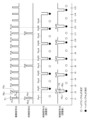
- FIG. 4 is a time chart of the vehicle lighting control device STS of Embodiment 1.
- FIG. 1 shows a configuration of a vehicle lighting control device STS of Embodiment 1; 4 is a flowchart showing the operation of the vehicle lighting control device STS of Embodiment 1;
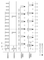
- FIG. 10 is a time chart (part 1) of the vehicle lighting control device STS of the second embodiment;
- FIG. FIG. 10 is a time chart (part 2) of the vehicle lighting control device STS of the second embodiment;
- FIG. 7 is a flow chart of the vehicle lighting control device STS of Embodiment 2.
- FIG. 1 shows a configuration of a vehicle lighting control device STS of Embodiment 1
- 4 is a flowchart showing the operation of the vehicle lighting control device STS of Embodiment 1
- FIG. 10 is a time chart (part 1) of the vehicle lighting control device STS of the second embodiment
- Embodiment 1 A vehicle lighting control device according to the first embodiment will be described.
- FIG. 1 is a functional block diagram of the vehicle lighting control device STS of Embodiment 1. As shown in FIG. 1
- the vehicle lighting control device STS of Embodiment 1 controls the lighting of the headlamps HL while checking the operation of the monitoring camera KK.
- a generating unit 13 and a driving unit 14 are included.
- the detection unit 12 corresponds to the "detection unit”
- the generation unit 13 corresponds to the “generation unit”
- the driving unit 14 corresponds to the "driving unit”.
- the surveillance camera KK corresponds to the "camera”
- the headlamp HL corresponds to the "headlamp”.
- the surveillance camera KK is a high-sensitivity camera capable of capturing images in a dark place such as at night, and is mounted on a vehicle (not shown) such as a private car in order to monitor the surroundings including the front. .
- the surveillance camera KK takes an image at a predetermined frame rate (for example, several tens of FPS (Frames Per Second)), more specifically, according to an imaging signal SS that defines the frame rate.
- a predetermined frame rate for example, several tens of FPS (Frames Per Second)
- FIG. 2 is a time chart of the vehicle lighting control device STS of the first embodiment.
- the imaging signal SS is composed of imaging pulses Ps1, Ps2, Ps3, .
- the surveillance camera KK takes images during time T1, which is the pulse width of a plurality of imaging pulses Ps1, Ps2, Ps3, . In other words, the surveillance camera KK does not image during the time T2, which is the interval between the imaging pulses Ps1, Ps2, Ps3, .
- the synchronization signal DS is, as shown in FIG. 2, a signal obtained by dividing the imaging signal SS (for example, 1/5 to 1/10).
- the synchronization signal DS is composed of a plurality of synchronization pulses Pd1, Pd2, Pd3, .
- the synchronization signal DS is synchronized with the imaging signal SS.
- the timing of the synchronization pulse Pd1 in the synchronization signal DS and the timing of the imaging pulse Ps1 in the imaging signal SS match.
- the timing of the synchronization pulse Pd2 in the signal DS and the timing of the imaging pulse Ps6 in the imaging signal SS match.
- detecting the synchronization pulse Pd1 and detecting the imaging pulse Ps1 have the same meaning.
- the imaging pulse Ps1 and the synchronization pulse Pd1 correspond to the "first imaging pulse”, and the imaging pulse Ps2 corresponds to the "second imaging pulse”.
- the headlamp HL is mounted on the above vehicle, just like the surveillance camera KK. As shown in FIG. 2, the headlamp HL is controlled to be turned on and off by a control signal CS for duty-controlling the illuminance of the headlamp HL by a duty ratio. Since the illuminance of the headlamp HL is regulated by law, the duty ratio is determined so as to satisfy the statutory illuminance in consideration of the specifications of the headlamp HL.
- Time T3 which is the pulse width of extinguishing pulses Poff1, Poff2, Poff3, .
- the relationship with time T1, which is the width, is generally time T3>T1.
- control signal CS (before adjustment) is the original control signal CS, and there is no guarantee that the extinguishing pulse Poff1 and the like in the control signal CS (before adjustment) are synchronized with the imaging pulse Ps1 and the like.
- control signal CS (after adjustment) is the control signal CS generated by the generator 13, more precisely, the control signal CS whose phase is adjusted by the generator 13.
- the extinguishing pulse Poff1, etc. in the control signal CS (after adjustment) is synchronized with the imaging pulse Ps1, etc.
- the extinguishing pulse Poff1 is synchronized with the imaging pulse Ps2.
- the control signal CS (before adjustment) is composed of lighting pulses Pon1, Pon2, Pon3, . . . and lighting pulses Poff1, Poff2, Poff3, .
- the headlamps HL are lit during the lighting pulses Pon1, Pon2, Pon3, .
- the control signal CS corresponds to the "control signal”
- the lighting pulse Pon corresponds to the "lighting pulse”
- the lighting pulse Poff corresponds to the "lighting out pulse”.
- the interface unit 11 continuously receives inputs of the imaging signal SS (also shown in FIG. 2) and the synchronization signal DS (also shown in FIG. 2) from the outside of the vehicle lighting control device STS. Note that the synchronization signal DS may be generated based on the imaging signal SS.
- the interface unit 11 functions, for example, as a part of CAN (Controller Area Network) and LIN (Local Interconnect Network).
- the detection unit 12 detects synchronization pulses Pd1, Pd2, Pd3, . . . that constitute the synchronization signal DS. More specifically, the detector 12 detects, for example, the rising edge REd or the falling edge FEd of the synchronization pulses Pd1, Pd2, Pd3, . . . , as shown in FIG.
- the generation unit 13 generates the control signal CS (also shown in FIG. 2). More specifically, when the detection unit 12 detects the synchronization pulse Pd1, for example, the timing of the extinguishing pulse Poff1 is set to the imaging pulse following the imaging pulse Ps1, for example, the imaging pulse immediately after the imaging pulse Ps1. The phase is adjusted so as to match the timing of Ps2, and the extinguishing pulse Poff1 is generated.
- the drive unit 14 controls lighting and extinguishing of the headlamps HL using drive signals KS for driving the headlamps HL according to the control signal CS generated by the generation unit 13 .
- FIG. 3 shows the configuration of the vehicle lighting control device STS of the first embodiment.
- the vehicle lighting control device STS of the embodiment includes a processor PC, a storage medium KB, a memory MM, and an input unit NY as shown in FIG. 3 in order to perform the functions described above (shown in FIG. 1). , an output SY. More precisely, the vehicle lighting control device STS includes an input section NY and an output section SY as required.
- a processor PC is the core of a well-known computer that operates hardware according to software.
- the storage medium KB is composed of, for example, a hard disk drive (HDD: Hard Disk Drive), a solid state drive (SSD: Solid State Drive), and a ROM (Read Only Memory).
- a storage medium KB stores a program PR.
- the program PR is a group of instructions that define the content of processing to be executed by the processor PC.
- the memory MM is composed of, for example, a DRAM (Dynamic Random Access Memory) and an SRAM (Static Random Access Memory).
- the input unit NY is, for example, an interface that receives signals from the outside of the vehicle lighting control device STS.
- the output unit SY is, for example, an interface that outputs a signal to the outside of the vehicle lighting control device STS.
- the processor PC executes the program PR stored in the storage medium KB on the memory MM. 14, and controls the operations of the input section NY and the output section SY as necessary.
- FIG. 4 is a flow chart showing the operation of the vehicle lighting control device STS of the first embodiment. The operation of the vehicle lighting control device STS of Embodiment 1 will be described below with reference to the flowchart of FIG. 4 and the time chart of FIG.
- Step ST11 The interface unit 11 (shown in FIG. 1) receives the imaging signal SS (shown in FIGS. 1 and 2) and/or the synchronization signal DS (shown in FIGS. 1 and 2) from the outside of the vehicle lighting control device STS. .), the detector 12 (shown in FIG. 1) detects the synchronization pulse Pd1 in the synchronization signal DS at time t1, for example, as shown in FIG.
- Step ST12 In step ST11, when the detection unit 12 detects the synchronization pulse Pd1 at time t1, the generation unit 13 (shown in FIG. 1) outputs the control signal CS (after adjustment) shown in FIG. Then, at time t2, a light-off pulse Poff1 is generated.
- the generation unit 13 generates the control signal CS (before adjustment) so that the timing of the extinguishing pulse Poff1 to constitute the control signal CS (after adjustment) is equal to the synchronization pulse Pd1 as shown in the control signal CS (after adjustment) in FIG.
- the extinguishing pulse Poff1 is generated by adjusting the phase so as to coincide with the timing of the imaging pulse Ps2 following the imaging pulse Ps1 synchronized with .
- the generator 13 may start generating the extinguishing pulse Poff1 described above, for example, at the timing of the rising edge REs of the imaging pulse Ps2. You can start when the time has passed. That is, the generation unit 13 should at least match the falling edge FEc of the extinguishing pulse Poff1 with the rising edge REs of the imaging pulse Ps2.
- the generation unit 13 completes the generation of the extinguishing pulse Poff1 by advancing the falling edge FEc.
- Step ST13 In step ST12, when the generating unit 13 generates the extinguishing pulse Poff1 of the control signal CS (after adjustment), the driving unit 14 extinguishes the headlamp HL by the driving signal KS according to the extinguishing pulse Poff1.
- the monitoring camera KK takes an image of, for example, the front of the vehicle according to the imaging pulse Ps2, more specifically according to the imaging pulse Ps2 positioned during the period when the headlamp HL is turned off.
- Step ST14 In step ST13, when the monitoring camera KK completes the imaging based on the imaging pulse Ps2, the monitoring camera KK follows the imaging pulses Ps3, Ps4, and Ps5 following the imaging pulse Ps2 to determine the time at which the headlamp HL is on. At times t3, t4, and t5, the front of the vehicle is imaged while the headlamp HL is on.
- Step ST15 In step ST14, when the imaging by the monitoring camera KK from time t3 to t5 is completed, the processing unit (not shown) divides the four images captured by the monitoring camera KK from time t2 to t5 into four images. , for example, performing an averaging process.
- the averaged image may be stored, for example, in a storage unit (not shown) and displayed on a display unit (not shown). Also, the image at time t2 may be used for monitoring dark places, and the images at times t3 to t5 may be used for monitoring bright places.
- step ST15 After time t6, the interface section 11 to drive section 14 repeat the same operations as those performed at times t1 to t5 in steps ST11 to ST15.
- the generation unit 13 adjusts the timing of the extinguishing pulse Poff1 so that the synchronization pulse Pd1 is
- the extinguishing pulse Poff1 is generated by adjusting the phase so as to coincide with the timing of the imaging pulse Ps2 following the synchronized imaging pulse Ps1, and the drive unit 14 extinguishes the headlamp HL according to the extinguishing pulse Poff1.
- the monitoring camera KK captures an image of the surroundings including the front of the vehicle with the headlamp HL turned off at the time of the imaging pulse Ps2.
- it is possible to reduce the occurrence of so-called overexposure that may occur due to imaging with the headlamp HL turned on. can reduce sexuality. That is, by adjusting the turn-off timing of the headlamp HL, overexposure is suppressed, and there is no need to modify the control or configuration of the camera.
- Embodiment 2 A vehicle lighting control device according to the second embodiment will be described.
- the vehicle lighting control device STS of the first embodiment matches the falling edge FEc of the extinguishing pulse Poff1 with the rising edge REs of the imaging pulse Ps2.
- the vehicle lighting control device STS of the second embodiment generates the falling edge FEc of the extinguishing pulse Poff1 earlier than the rising edge REs of the imaging pulse Ps2.
- the rising edge REc of the extinguishing pulse Poff1 is generated at a timing later than the falling edge FEs of the imaging pulse Ps2.
- the vehicle lighting control device STS of the second embodiment adjusts the phase so that the turn-off pulse Poff1 continues to turn off the headlamp HL over the time period during which the monitoring camera KK is capturing images according to the imaging pulse Ps2. and generates the extinguishing pulse Poff1.
- FIG. 5 is a time chart (part 1) of the vehicle lighting control device STS of the second embodiment.
- FIG. 6 is a time chart (part 2) of the vehicle lighting control device STS of the second embodiment.
- FIG. 7 is a flowchart of the vehicle lighting control device STS of the second embodiment.
- Step ST21 As in step ST11 of the first embodiment, the detector 12 detects the synchronization pulse Pd1 in the synchronization signal DS at time t1, as shown in FIGS.
- Step ST22 As shown in FIG. 6, the generator 13 generates the control signal CS ( after adjustment), the extinguishing pulse Poff1 is generated so that the imaging pulse Ps2 includes the timing positioned in the center of the extinguishing pulse Poff1.
- Step ST23 As shown in FIGS. 5 and 6, the drive unit 14 turns off the headlamp HL only during the period of the turn-off pulse Poff1, and the monitoring camera KK detects the An image is captured according to the imaging pulse Ps2.
- Step ST24 As in step ST14 of the first embodiment, the monitoring camera KK takes images according to the imaging pulses Ps3, Ps4, and Ps5 while the headlamps HL are on.
- Step ST25 As in step ST15 of Embodiment 1, the processing unit averages the four images captured at times t2 to t5, and stores the averaged images in a storage unit (not shown). The image is stored, and a display unit (not shown) may display the image subjected to the averaging process. Also, the image at time t2 may be used for monitoring dark places, and the images at times t3 to t5 may be used for monitoring bright places.
- the monitoring camera KK controls the headlamps HL in accordance with the light-off pulse Poff1 while the headlamps HL are turned off. , the imaging is performed according to the imaging pulse Ps2, so that the occurrence of so-called whiteout can be reduced as in the vehicle lighting control device STS of the first embodiment. That is, by adjusting the turn-off timing of the headlamp HL, overexposure is suppressed, and there is no need to modify the control or configuration of the camera.
- the turn-off pulse Poff1 is set such that the timing at which the monitoring camera KK captures images according to the imaging pulse Ps2 includes the timing positioned at the center of the turn-off pulse Poff1. Generate.
- the surveillance camera KK can take an image without turning on the headlamp HL during the image taking according to the image pickup pulse Ps2, thereby more reliably reducing the above-described overexposure. becomes possible.
- the vehicle lighting control device can be used, for example, to capture an image of the surroundings of the vehicle under vehicle lighting.
Landscapes
- Engineering & Computer Science (AREA)
- Mechanical Engineering (AREA)
- Lighting Device Outwards From Vehicle And Optical Signal (AREA)
Priority Applications (2)
| Application Number | Priority Date | Filing Date | Title |
|---|---|---|---|
| PCT/JP2021/038506 WO2023067670A1 (ja) | 2021-10-19 | 2021-10-19 | 車両用点灯制御装置、及び車両用点灯制御方法 |
| JP2023553922A JP7475556B2 (ja) | 2021-10-19 | 2021-10-19 | 車両用点灯制御装置、及び車両用点灯制御方法 |
Applications Claiming Priority (1)
| Application Number | Priority Date | Filing Date | Title |
|---|---|---|---|
| PCT/JP2021/038506 WO2023067670A1 (ja) | 2021-10-19 | 2021-10-19 | 車両用点灯制御装置、及び車両用点灯制御方法 |
Publications (1)
| Publication Number | Publication Date |
|---|---|
| WO2023067670A1 true WO2023067670A1 (ja) | 2023-04-27 |
Family
ID=86058900
Family Applications (1)
| Application Number | Title | Priority Date | Filing Date |
|---|---|---|---|
| PCT/JP2021/038506 Ceased WO2023067670A1 (ja) | 2021-10-19 | 2021-10-19 | 車両用点灯制御装置、及び車両用点灯制御方法 |
Country Status (2)
| Country | Link |
|---|---|
| JP (1) | JP7475556B2 (https=) |
| WO (1) | WO2023067670A1 (https=) |
Citations (5)
| Publication number | Priority date | Publication date | Assignee | Title |
|---|---|---|---|---|
| JP2007251258A (ja) * | 2006-03-13 | 2007-09-27 | Fujitsu Ten Ltd | 画像認識装置 |
| JP2011209961A (ja) * | 2010-03-29 | 2011-10-20 | Kyocera Corp | 車載用撮像装置 |
| WO2018173715A1 (ja) * | 2017-03-21 | 2018-09-27 | コニカミノルタ株式会社 | 照明撮像装置 |
| JP2019041351A (ja) * | 2017-08-29 | 2019-03-14 | 株式会社Jvcケンウッド | 画像生成制御装置、画像生成制御方法、及び画像生成制御プログラム |
| JP2020152193A (ja) * | 2019-03-19 | 2020-09-24 | 株式会社小糸製作所 | 車両用監視システム |
Family Cites Families (1)
| Publication number | Priority date | Publication date | Assignee | Title |
|---|---|---|---|---|
| CN115349251B (zh) * | 2020-03-23 | 2024-05-10 | 株式会社小糸制作所 | 摄像系统 |
-
2021
- 2021-10-19 JP JP2023553922A patent/JP7475556B2/ja active Active
- 2021-10-19 WO PCT/JP2021/038506 patent/WO2023067670A1/ja not_active Ceased
Patent Citations (5)
| Publication number | Priority date | Publication date | Assignee | Title |
|---|---|---|---|---|
| JP2007251258A (ja) * | 2006-03-13 | 2007-09-27 | Fujitsu Ten Ltd | 画像認識装置 |
| JP2011209961A (ja) * | 2010-03-29 | 2011-10-20 | Kyocera Corp | 車載用撮像装置 |
| WO2018173715A1 (ja) * | 2017-03-21 | 2018-09-27 | コニカミノルタ株式会社 | 照明撮像装置 |
| JP2019041351A (ja) * | 2017-08-29 | 2019-03-14 | 株式会社Jvcケンウッド | 画像生成制御装置、画像生成制御方法、及び画像生成制御プログラム |
| JP2020152193A (ja) * | 2019-03-19 | 2020-09-24 | 株式会社小糸製作所 | 車両用監視システム |
Also Published As
| Publication number | Publication date |
|---|---|
| JPWO2023067670A1 (https=) | 2023-04-27 |
| JP7475556B2 (ja) | 2024-04-26 |
Similar Documents
| Publication | Publication Date | Title |
|---|---|---|
| JP4484856B2 (ja) | 自動車用ヘッドライト制御装置 | |
| CN110933337B (zh) | 具有led闪烁减轻和减少运动模糊的hdr图像传感器 | |
| CN107709096A (zh) | 用于处理流式传输视频图像以校正经调幅光的闪变的系统和方法 | |
| CN107896307A (zh) | 具有高动态范围渲染功能的成像装置 | |
| WO2023067670A1 (ja) | 車両用点灯制御装置、及び車両用点灯制御方法 | |
| JP2007076429A (ja) | ヘッドランプシステム | |
| US11363211B2 (en) | Image generation control device, image generation control method, and image generation control program | |
| JP6935815B2 (ja) | 照明撮像装置 | |
| WO2022190166A1 (ja) | 画像処理装置、画像処理方法、及び、画像処理プログラム | |
| WO2023067671A1 (ja) | 車両用点灯制御装置、及び車両用点灯制御方法 | |
| CN112565618B (zh) | 曝光控制装置 | |
| JP2003087644A (ja) | 撮像表示装置、撮像表示方法及びプログラム | |
| JP4270638B2 (ja) | 撮像装置 | |
| JP5838587B2 (ja) | 移動体監視装置及び移動体監視システム | |
| JP2006339994A (ja) | 車載カメラ制御装置 | |
| JP2012075059A (ja) | 画像処理装置 | |
| JP6999231B2 (ja) | 表示制御装置、表示制御方法及びカメラモニタリングシステム | |
| JP2006287513A (ja) | 車両外状況提示システム | |
| KR20220086388A (ko) | 차량의 동작 제어 장치 및 방법 | |
| JP2009027666A (ja) | Led信号機対策用カメラ付きレコーダ | |
| JP6759995B2 (ja) | 画像処理装置 | |
| JP6944310B2 (ja) | 特定対象物検出装置 | |
| JP2013090294A (ja) | 車両周辺監視装置 | |
| JP7630968B2 (ja) | 制御装置、制御システムおよび撮影画像データの記憶方法 | |
| JP2024042359A (ja) | 点灯制御用のコントローラ、車両用灯具システム |
Legal Events
| Date | Code | Title | Description |
|---|---|---|---|
| 121 | Ep: the epo has been informed by wipo that ep was designated in this application |
Ref document number: 21961323 Country of ref document: EP Kind code of ref document: A1 |
|
| WWE | Wipo information: entry into national phase |
Ref document number: 2023553922 Country of ref document: JP |
|
| NENP | Non-entry into the national phase |
Ref country code: DE |
|
| 122 | Ep: pct application non-entry in european phase |
Ref document number: 21961323 Country of ref document: EP Kind code of ref document: A1 |