WO2023067670A1 - Vehicular lighting control device and vehicular lighting control method - Google Patents
Vehicular lighting control device and vehicular lighting control method Download PDFInfo
- Publication number
- WO2023067670A1 WO2023067670A1 PCT/JP2021/038506 JP2021038506W WO2023067670A1 WO 2023067670 A1 WO2023067670 A1 WO 2023067670A1 JP 2021038506 W JP2021038506 W JP 2021038506W WO 2023067670 A1 WO2023067670 A1 WO 2023067670A1
- Authority
- WO
- WIPO (PCT)
- Prior art keywords
- pulse
- imaging
- lighting control
- timing
- headlamp
- Prior art date
Links
- 238000000034 method Methods 0.000 title claims description 7
- 238000001514 detection method Methods 0.000 claims abstract description 11
- 238000003384 imaging method Methods 0.000 claims description 75
- 238000012544 monitoring process Methods 0.000 description 17
- 239000008186 active pharmaceutical agent Substances 0.000 description 13
- 230000006870 function Effects 0.000 description 6
- 230000000630 rising effect Effects 0.000 description 6
- 230000001360 synchronised effect Effects 0.000 description 6
- 101150100678 Pon1 gene Proteins 0.000 description 4
- 230000000694 effects Effects 0.000 description 3
- 238000012935 Averaging Methods 0.000 description 2
- 101000710013 Homo sapiens Reversion-inducing cysteine-rich protein with Kazal motifs Proteins 0.000 description 2
- 101150043906 Pon2 gene Proteins 0.000 description 2
- 101150098895 Pon3 gene Proteins 0.000 description 2
- 238000010586 diagram Methods 0.000 description 2
- 238000005286 illumination Methods 0.000 description 2
- 230000002265 prevention Effects 0.000 description 2
- 239000007787 solid Substances 0.000 description 2
- 101000911772 Homo sapiens Hsc70-interacting protein Proteins 0.000 description 1
- 101001139126 Homo sapiens Krueppel-like factor 6 Proteins 0.000 description 1
- 101000661807 Homo sapiens Suppressor of tumorigenicity 14 protein Proteins 0.000 description 1
- 230000001105 regulatory effect Effects 0.000 description 1
- 230000003068 static effect Effects 0.000 description 1
Images


Classifications
-
- B—PERFORMING OPERATIONS; TRANSPORTING
- B60—VEHICLES IN GENERAL
- B60Q—ARRANGEMENT OF SIGNALLING OR LIGHTING DEVICES, THE MOUNTING OR SUPPORTING THEREOF OR CIRCUITS THEREFOR, FOR VEHICLES IN GENERAL
- B60Q1/00—Arrangement of optical signalling or lighting devices, the mounting or supporting thereof or circuits therefor
- B60Q1/02—Arrangement of optical signalling or lighting devices, the mounting or supporting thereof or circuits therefor the devices being primarily intended to illuminate the way ahead or to illuminate other areas of way or environments
- B60Q1/04—Arrangement of optical signalling or lighting devices, the mounting or supporting thereof or circuits therefor the devices being primarily intended to illuminate the way ahead or to illuminate other areas of way or environments the devices being headlights
Definitions
- the present disclosure relates to a vehicle lighting control device and a vehicle lighting control method.
- the purpose of the illumination imaging device described in Patent Document 1 is to acquire an image of a subject in an environment where high-intensity light such as headlights from oncoming vehicles is emitted at night.
- the illumination imaging device is an image of a subject and a high-brightness subject captured with the light-emitting unit turned on, wherein the image of the high-brightness subject exceeds the dynamic range of the camera.
- the image of the high-brightness subject imaged with the light emitting unit turned off is removed from the image.
- some vehicles are equipped with a high-sensitivity camera capable of taking pictures even in a dark place such as at night for the purpose of crime prevention. It is conceivable to use this high-sensitivity camera to monitor the surroundings while the vehicle is in use.
- this high-sensitivity camera to monitor the surroundings while the vehicle is in use.
- white parts for example, the image of a white license plate, which exceeds the limit of the dynamic range of the high-sensitivity camera, become completely white, so-called blown-out highlights may occur.
- An object of the present disclosure is to provide a vehicle lighting control device and a vehicle lighting control method that can reduce the occurrence of blown-out highlights in a captured image.
- a lighting control device for a vehicle is capable of shooting in a dark place, and defines the timing at which a camera should shoot according to a predetermined frame rate.
- a detection unit that detects an imaging pulse and a control signal that outputs a control signal for duty-controlling a headlamp provided in a vehicle with a predetermined duty ratio, when the first imaging pulse is detected a generator for changing the timing of turning off the headlamp and generating a turn-off pulse so as to match the timing of a second imaging pulse that follows the first imaging pulse; and turning off the headlamp according to the turn-off pulse. and a drive for driving to.
- the vehicle lighting control device it is possible to reduce the occurrence of blown-out highlights in the captured image.
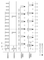
- FIG. 2 is a functional block diagram of the vehicle lighting control device STS of Embodiment 1.
- FIG. 4 is a time chart of the vehicle lighting control device STS of Embodiment 1.
- FIG. 1 shows a configuration of a vehicle lighting control device STS of Embodiment 1; 4 is a flowchart showing the operation of the vehicle lighting control device STS of Embodiment 1;
- FIG. 10 is a time chart (part 1) of the vehicle lighting control device STS of the second embodiment;
- FIG. FIG. 10 is a time chart (part 2) of the vehicle lighting control device STS of the second embodiment;
- FIG. 7 is a flow chart of the vehicle lighting control device STS of Embodiment 2.
- FIG. 1 shows a configuration of a vehicle lighting control device STS of Embodiment 1
- 4 is a flowchart showing the operation of the vehicle lighting control device STS of Embodiment 1
- FIG. 10 is a time chart (part 1) of the vehicle lighting control device STS of the second embodiment
- Embodiment 1 A vehicle lighting control device according to the first embodiment will be described.
- FIG. 1 is a functional block diagram of the vehicle lighting control device STS of Embodiment 1. As shown in FIG. 1
- the vehicle lighting control device STS of Embodiment 1 controls the lighting of the headlamps HL while checking the operation of the monitoring camera KK.
- a generating unit 13 and a driving unit 14 are included.
- the detection unit 12 corresponds to the "detection unit”
- the generation unit 13 corresponds to the “generation unit”
- the driving unit 14 corresponds to the "driving unit”.
- the surveillance camera KK corresponds to the "camera”
- the headlamp HL corresponds to the "headlamp”.
- the surveillance camera KK is a high-sensitivity camera capable of capturing images in a dark place such as at night, and is mounted on a vehicle (not shown) such as a private car in order to monitor the surroundings including the front. .
- the surveillance camera KK takes an image at a predetermined frame rate (for example, several tens of FPS (Frames Per Second)), more specifically, according to an imaging signal SS that defines the frame rate.
- a predetermined frame rate for example, several tens of FPS (Frames Per Second)
- FIG. 2 is a time chart of the vehicle lighting control device STS of the first embodiment.
- the imaging signal SS is composed of imaging pulses Ps1, Ps2, Ps3, .
- the surveillance camera KK takes images during time T1, which is the pulse width of a plurality of imaging pulses Ps1, Ps2, Ps3, . In other words, the surveillance camera KK does not image during the time T2, which is the interval between the imaging pulses Ps1, Ps2, Ps3, .
- the synchronization signal DS is, as shown in FIG. 2, a signal obtained by dividing the imaging signal SS (for example, 1/5 to 1/10).
- the synchronization signal DS is composed of a plurality of synchronization pulses Pd1, Pd2, Pd3, .
- the synchronization signal DS is synchronized with the imaging signal SS.
- the timing of the synchronization pulse Pd1 in the synchronization signal DS and the timing of the imaging pulse Ps1 in the imaging signal SS match.
- the timing of the synchronization pulse Pd2 in the signal DS and the timing of the imaging pulse Ps6 in the imaging signal SS match.
- detecting the synchronization pulse Pd1 and detecting the imaging pulse Ps1 have the same meaning.
- the imaging pulse Ps1 and the synchronization pulse Pd1 correspond to the "first imaging pulse”, and the imaging pulse Ps2 corresponds to the "second imaging pulse”.
- the headlamp HL is mounted on the above vehicle, just like the surveillance camera KK. As shown in FIG. 2, the headlamp HL is controlled to be turned on and off by a control signal CS for duty-controlling the illuminance of the headlamp HL by a duty ratio. Since the illuminance of the headlamp HL is regulated by law, the duty ratio is determined so as to satisfy the statutory illuminance in consideration of the specifications of the headlamp HL.
- Time T3 which is the pulse width of extinguishing pulses Poff1, Poff2, Poff3, .
- the relationship with time T1, which is the width, is generally time T3>T1.
- control signal CS (before adjustment) is the original control signal CS, and there is no guarantee that the extinguishing pulse Poff1 and the like in the control signal CS (before adjustment) are synchronized with the imaging pulse Ps1 and the like.
- control signal CS (after adjustment) is the control signal CS generated by the generator 13, more precisely, the control signal CS whose phase is adjusted by the generator 13.
- the extinguishing pulse Poff1, etc. in the control signal CS (after adjustment) is synchronized with the imaging pulse Ps1, etc.
- the extinguishing pulse Poff1 is synchronized with the imaging pulse Ps2.
- the control signal CS (before adjustment) is composed of lighting pulses Pon1, Pon2, Pon3, . . . and lighting pulses Poff1, Poff2, Poff3, .
- the headlamps HL are lit during the lighting pulses Pon1, Pon2, Pon3, .
- the control signal CS corresponds to the "control signal”
- the lighting pulse Pon corresponds to the "lighting pulse”
- the lighting pulse Poff corresponds to the "lighting out pulse”.
- the interface unit 11 continuously receives inputs of the imaging signal SS (also shown in FIG. 2) and the synchronization signal DS (also shown in FIG. 2) from the outside of the vehicle lighting control device STS. Note that the synchronization signal DS may be generated based on the imaging signal SS.
- the interface unit 11 functions, for example, as a part of CAN (Controller Area Network) and LIN (Local Interconnect Network).
- the detection unit 12 detects synchronization pulses Pd1, Pd2, Pd3, . . . that constitute the synchronization signal DS. More specifically, the detector 12 detects, for example, the rising edge REd or the falling edge FEd of the synchronization pulses Pd1, Pd2, Pd3, . . . , as shown in FIG.
- the generation unit 13 generates the control signal CS (also shown in FIG. 2). More specifically, when the detection unit 12 detects the synchronization pulse Pd1, for example, the timing of the extinguishing pulse Poff1 is set to the imaging pulse following the imaging pulse Ps1, for example, the imaging pulse immediately after the imaging pulse Ps1. The phase is adjusted so as to match the timing of Ps2, and the extinguishing pulse Poff1 is generated.
- the drive unit 14 controls lighting and extinguishing of the headlamps HL using drive signals KS for driving the headlamps HL according to the control signal CS generated by the generation unit 13 .
- FIG. 3 shows the configuration of the vehicle lighting control device STS of the first embodiment.
- the vehicle lighting control device STS of the embodiment includes a processor PC, a storage medium KB, a memory MM, and an input unit NY as shown in FIG. 3 in order to perform the functions described above (shown in FIG. 1). , an output SY. More precisely, the vehicle lighting control device STS includes an input section NY and an output section SY as required.
- a processor PC is the core of a well-known computer that operates hardware according to software.
- the storage medium KB is composed of, for example, a hard disk drive (HDD: Hard Disk Drive), a solid state drive (SSD: Solid State Drive), and a ROM (Read Only Memory).
- a storage medium KB stores a program PR.
- the program PR is a group of instructions that define the content of processing to be executed by the processor PC.
- the memory MM is composed of, for example, a DRAM (Dynamic Random Access Memory) and an SRAM (Static Random Access Memory).
- the input unit NY is, for example, an interface that receives signals from the outside of the vehicle lighting control device STS.
- the output unit SY is, for example, an interface that outputs a signal to the outside of the vehicle lighting control device STS.
- the processor PC executes the program PR stored in the storage medium KB on the memory MM. 14, and controls the operations of the input section NY and the output section SY as necessary.
- FIG. 4 is a flow chart showing the operation of the vehicle lighting control device STS of the first embodiment. The operation of the vehicle lighting control device STS of Embodiment 1 will be described below with reference to the flowchart of FIG. 4 and the time chart of FIG.
- Step ST11 The interface unit 11 (shown in FIG. 1) receives the imaging signal SS (shown in FIGS. 1 and 2) and/or the synchronization signal DS (shown in FIGS. 1 and 2) from the outside of the vehicle lighting control device STS. .), the detector 12 (shown in FIG. 1) detects the synchronization pulse Pd1 in the synchronization signal DS at time t1, for example, as shown in FIG.
- Step ST12 In step ST11, when the detection unit 12 detects the synchronization pulse Pd1 at time t1, the generation unit 13 (shown in FIG. 1) outputs the control signal CS (after adjustment) shown in FIG. Then, at time t2, a light-off pulse Poff1 is generated.
- the generation unit 13 generates the control signal CS (before adjustment) so that the timing of the extinguishing pulse Poff1 to constitute the control signal CS (after adjustment) is equal to the synchronization pulse Pd1 as shown in the control signal CS (after adjustment) in FIG.
- the extinguishing pulse Poff1 is generated by adjusting the phase so as to coincide with the timing of the imaging pulse Ps2 following the imaging pulse Ps1 synchronized with .
- the generator 13 may start generating the extinguishing pulse Poff1 described above, for example, at the timing of the rising edge REs of the imaging pulse Ps2. You can start when the time has passed. That is, the generation unit 13 should at least match the falling edge FEc of the extinguishing pulse Poff1 with the rising edge REs of the imaging pulse Ps2.
- the generation unit 13 completes the generation of the extinguishing pulse Poff1 by advancing the falling edge FEc.
- Step ST13 In step ST12, when the generating unit 13 generates the extinguishing pulse Poff1 of the control signal CS (after adjustment), the driving unit 14 extinguishes the headlamp HL by the driving signal KS according to the extinguishing pulse Poff1.
- the monitoring camera KK takes an image of, for example, the front of the vehicle according to the imaging pulse Ps2, more specifically according to the imaging pulse Ps2 positioned during the period when the headlamp HL is turned off.
- Step ST14 In step ST13, when the monitoring camera KK completes the imaging based on the imaging pulse Ps2, the monitoring camera KK follows the imaging pulses Ps3, Ps4, and Ps5 following the imaging pulse Ps2 to determine the time at which the headlamp HL is on. At times t3, t4, and t5, the front of the vehicle is imaged while the headlamp HL is on.
- Step ST15 In step ST14, when the imaging by the monitoring camera KK from time t3 to t5 is completed, the processing unit (not shown) divides the four images captured by the monitoring camera KK from time t2 to t5 into four images. , for example, performing an averaging process.
- the averaged image may be stored, for example, in a storage unit (not shown) and displayed on a display unit (not shown). Also, the image at time t2 may be used for monitoring dark places, and the images at times t3 to t5 may be used for monitoring bright places.
- step ST15 After time t6, the interface section 11 to drive section 14 repeat the same operations as those performed at times t1 to t5 in steps ST11 to ST15.
- the generation unit 13 adjusts the timing of the extinguishing pulse Poff1 so that the synchronization pulse Pd1 is
- the extinguishing pulse Poff1 is generated by adjusting the phase so as to coincide with the timing of the imaging pulse Ps2 following the synchronized imaging pulse Ps1, and the drive unit 14 extinguishes the headlamp HL according to the extinguishing pulse Poff1.
- the monitoring camera KK captures an image of the surroundings including the front of the vehicle with the headlamp HL turned off at the time of the imaging pulse Ps2.
- it is possible to reduce the occurrence of so-called overexposure that may occur due to imaging with the headlamp HL turned on. can reduce sexuality. That is, by adjusting the turn-off timing of the headlamp HL, overexposure is suppressed, and there is no need to modify the control or configuration of the camera.
- Embodiment 2 A vehicle lighting control device according to the second embodiment will be described.
- the vehicle lighting control device STS of the first embodiment matches the falling edge FEc of the extinguishing pulse Poff1 with the rising edge REs of the imaging pulse Ps2.
- the vehicle lighting control device STS of the second embodiment generates the falling edge FEc of the extinguishing pulse Poff1 earlier than the rising edge REs of the imaging pulse Ps2.
- the rising edge REc of the extinguishing pulse Poff1 is generated at a timing later than the falling edge FEs of the imaging pulse Ps2.
- the vehicle lighting control device STS of the second embodiment adjusts the phase so that the turn-off pulse Poff1 continues to turn off the headlamp HL over the time period during which the monitoring camera KK is capturing images according to the imaging pulse Ps2. and generates the extinguishing pulse Poff1.
- FIG. 5 is a time chart (part 1) of the vehicle lighting control device STS of the second embodiment.
- FIG. 6 is a time chart (part 2) of the vehicle lighting control device STS of the second embodiment.
- FIG. 7 is a flowchart of the vehicle lighting control device STS of the second embodiment.
- Step ST21 As in step ST11 of the first embodiment, the detector 12 detects the synchronization pulse Pd1 in the synchronization signal DS at time t1, as shown in FIGS.
- Step ST22 As shown in FIG. 6, the generator 13 generates the control signal CS ( after adjustment), the extinguishing pulse Poff1 is generated so that the imaging pulse Ps2 includes the timing positioned in the center of the extinguishing pulse Poff1.
- Step ST23 As shown in FIGS. 5 and 6, the drive unit 14 turns off the headlamp HL only during the period of the turn-off pulse Poff1, and the monitoring camera KK detects the An image is captured according to the imaging pulse Ps2.
- Step ST24 As in step ST14 of the first embodiment, the monitoring camera KK takes images according to the imaging pulses Ps3, Ps4, and Ps5 while the headlamps HL are on.
- Step ST25 As in step ST15 of Embodiment 1, the processing unit averages the four images captured at times t2 to t5, and stores the averaged images in a storage unit (not shown). The image is stored, and a display unit (not shown) may display the image subjected to the averaging process. Also, the image at time t2 may be used for monitoring dark places, and the images at times t3 to t5 may be used for monitoring bright places.
- the monitoring camera KK controls the headlamps HL in accordance with the light-off pulse Poff1 while the headlamps HL are turned off. , the imaging is performed according to the imaging pulse Ps2, so that the occurrence of so-called whiteout can be reduced as in the vehicle lighting control device STS of the first embodiment. That is, by adjusting the turn-off timing of the headlamp HL, overexposure is suppressed, and there is no need to modify the control or configuration of the camera.
- the turn-off pulse Poff1 is set such that the timing at which the monitoring camera KK captures images according to the imaging pulse Ps2 includes the timing positioned at the center of the turn-off pulse Poff1. Generate.
- the surveillance camera KK can take an image without turning on the headlamp HL during the image taking according to the image pickup pulse Ps2, thereby more reliably reducing the above-described overexposure. becomes possible.
- the vehicle lighting control device can be used, for example, to capture an image of the surroundings of the vehicle under vehicle lighting.
Landscapes
- Engineering & Computer Science (AREA)
- Mechanical Engineering (AREA)
- Lighting Device Outwards From Vehicle And Optical Signal (AREA)
Abstract
A vehicular lighting control device (STS) includes: a detection unit (12) that detects a first image capturing pulse (Ps1) dictating a timing for image capturing by a camera (KK) that is capable of photographing in a dark place and that is to capture images according to a predefined frame rate; a generation unit (13) that outputs a control signal for controlling, with a predefined duty ratio, the duty of a headlamp (HL) provided in a vehicle, wherein when the first image capturing pulse (Ps1) is detected, the generation unit (13) changes the timing for turning off the headlamp (HL) and generates a turn-off pulse (Poff1) such that the timing thereof coincides with the timing of a second image capturing pulse (Ps2), which follows the first image capturing pulse (Ps1); and a drive unit (14) that drives the headlamp (HL) so as to turn off the headlamp (HL) according to the turn-off pulse (Poff1).
Description
本開示は、車両用点灯制御装置、及び車両用点灯制御方法に関する。
The present disclosure relates to a vehicle lighting control device and a vehicle lighting control method.
特許文献1に記載の照明撮像装置では、夜間の対向車からヘッドライト等の高強度光が照射されている環境の中で被写体の画像を取得することを目的とする。前記照明撮像装置は、前記目的を達成すべく、発光部が点灯した下で撮像された被写体及び高輝度被写体の画像であって前記高輝度被写体の部分の画像がカメラのダイナミックレンジを超えている前記画像から、発光部が消灯した下で撮像された前記高輝度被写体の部分の画像を除去する。
The purpose of the illumination imaging device described in Patent Document 1 is to acquire an image of a subject in an environment where high-intensity light such as headlights from oncoming vehicles is emitted at night. In order to achieve the object, the illumination imaging device is an image of a subject and a high-brightness subject captured with the light-emitting unit turned on, wherein the image of the high-brightness subject exceeds the dynamic range of the camera. The image of the high-brightness subject imaged with the light emitting unit turned off is removed from the image.
ところで車両には防犯用の目的で夜間などの暗所でも撮影が可能な高感度カメラを備えていることがある。この高感度カメラを利用して車両の使用時に周囲を監視することが考えられる。
しかしながら、上記した環境とは相違し、夜間に自車のヘッドライトが照射している環境の中では、夜間駐車の防犯用の高感度カメラを用いて前車を含む周囲を撮像した場合、前記撮像された範囲のうち、前記高感度カメラのダイナミックレンジの限界を超えるほどに白い部分、例えば、白いナンバープレートの画像が真っ白くなるという、いわゆる白飛びが生じることがあった。 By the way, some vehicles are equipped with a high-sensitivity camera capable of taking pictures even in a dark place such as at night for the purpose of crime prevention. It is conceivable to use this high-sensitivity camera to monitor the surroundings while the vehicle is in use.
However, unlike the environment described above, in an environment where the headlights of the own vehicle are illuminated at night, when the surroundings including the vehicle in front are imaged using a high-sensitivity camera for crime prevention when parked at night, the above-mentioned In the imaged range, white parts, for example, the image of a white license plate, which exceeds the limit of the dynamic range of the high-sensitivity camera, become completely white, so-called blown-out highlights may occur.
本開示の目的は、撮像された画像中に白飛びが発生することを低減することができる車両用点灯制御装置及び車両用点灯制御方法を提供することにある。
An object of the present disclosure is to provide a vehicle lighting control device and a vehicle lighting control method that can reduce the occurrence of blown-out highlights in a captured image.
上記した課題を解決すべく、本開示に係る車両用点灯制御装置は、暗所での撮影が可能であり、予め定められたフレームレートに従って撮像すべきカメラが撮像するタイミングを規定する第1の撮像パルスを検出する検出部と、車両に設けられたヘッドランプを予め定められたデューティ比によりデューティ制御するための制御信号を出力するものであって、前記第1の撮像パルスが検出されたとき前記ヘッドランプを消灯するタイミングを変更して前記第1の撮像パルスに後続する第2の撮像パルスのタイミングに一致するように消灯パルスを生成する生成部と、前記消灯パルスに従って前記ヘッドランプを消灯に駆動する駆動部と、を含む。
In order to solve the above-described problems, a lighting control device for a vehicle according to the present disclosure is capable of shooting in a dark place, and defines the timing at which a camera should shoot according to a predetermined frame rate. A detection unit that detects an imaging pulse and a control signal that outputs a control signal for duty-controlling a headlamp provided in a vehicle with a predetermined duty ratio, when the first imaging pulse is detected a generator for changing the timing of turning off the headlamp and generating a turn-off pulse so as to match the timing of a second imaging pulse that follows the first imaging pulse; and turning off the headlamp according to the turn-off pulse. and a drive for driving to.
本開示に係る車両用点灯制御装置によれば、撮像された画像中に白飛びが発生することを低減することができる。
According to the vehicle lighting control device according to the present disclosure, it is possible to reduce the occurrence of blown-out highlights in the captured image.
本開示に係る車両用点灯制御装置の実施形態について説明する。
An embodiment of a vehicle lighting control device according to the present disclosure will be described.
実施の形態1.
〈実施形態1〉
実施形態1の車両用点灯制御装置について説明する。 Embodiment 1.
<Embodiment 1>
A vehicle lighting control device according to the first embodiment will be described.
〈実施形態1〉
実施形態1の車両用点灯制御装置について説明する。 Embodiment 1.
<Embodiment 1>
A vehicle lighting control device according to the first embodiment will be described.
〈実施形態1の機能〉
図1は、実施形態1の車両用点灯制御装置STSの機能ブロック図である。 <Functions of Embodiment 1>
FIG. 1 is a functional block diagram of the vehicle lighting control device STS of Embodiment 1. As shown in FIG.
図1は、実施形態1の車両用点灯制御装置STSの機能ブロック図である。 <Functions of Embodiment 1>
FIG. 1 is a functional block diagram of the vehicle lighting control device STS of Embodiment 1. As shown in FIG.
実施形態1の車両用点灯制御装置STSは、図1に示されるように、監視カメラKKの動作を確認しつつ、ヘッドランプHLの点灯を制御すべく、インターフェイス部11と、検出部12と、生成部13、駆動部14と、を含む。
As shown in FIG. 1, the vehicle lighting control device STS of Embodiment 1 controls the lighting of the headlamps HL while checking the operation of the monitoring camera KK. A generating unit 13 and a driving unit 14 are included.
検出部12は、「検出部」に対応し、生成部13は、「生成部」に対応し、駆動部14は、「駆動部」に対応する。
The detection unit 12 corresponds to the "detection unit", the generation unit 13 corresponds to the "generation unit", and the driving unit 14 corresponds to the "driving unit".
監視カメラKKは、「カメラ」に対応し、ヘッドランプHLは、「ヘッドランプ」に対応する。
The surveillance camera KK corresponds to the "camera", and the headlamp HL corresponds to the "headlamp".
車両用点灯制御装置STSの説明に先立ち、監視カメラKK及びヘッドランプHLについて説明する。
Before explaining the vehicle lighting control device STS, the monitoring camera KK and the headlamp HL will be explained.
監視カメラKKは、夜間等の暗所での撮像が可能な高感度カメラであり、自家用車等の車両(図示なし。)の前方を含めた周囲を監視すべく、前記車両に搭載されている。監視カメラKKは、予め定められたフレームレート(例えば、数十FPS(Frames Per Second))で撮像し、より詳しくは、前記フレームレートを規定する撮像信号SSに従って撮像する。
The surveillance camera KK is a high-sensitivity camera capable of capturing images in a dark place such as at night, and is mounted on a vehicle (not shown) such as a private car in order to monitor the surroundings including the front. . The surveillance camera KK takes an image at a predetermined frame rate (for example, several tens of FPS (Frames Per Second)), more specifically, according to an imaging signal SS that defines the frame rate.
図2は、実施形態1の車両用点灯制御装置STSのタイムチャートである。
FIG. 2 is a time chart of the vehicle lighting control device STS of the first embodiment.
撮像信号SSは、図2に示されるように、監視カメラKKが撮影するタイミングを規定する複数のパルスである撮像パルスPs1、Ps2、Ps3、、、、から構成されている。監視カメラKKは、複数の撮像パルスPs1、Ps2、Ps3、、、、のパルス幅である時間T1の間に撮像する。監視カメラKKは、換言すれば、撮像パルスPs1、Ps2、Ps3、、、、の相互間の間隔である時間T2の間には、撮像しない。
As shown in FIG. 2, the imaging signal SS is composed of imaging pulses Ps1, Ps2, Ps3, . The surveillance camera KK takes images during time T1, which is the pulse width of a plurality of imaging pulses Ps1, Ps2, Ps3, . In other words, the surveillance camera KK does not image during the time T2, which is the interval between the imaging pulses Ps1, Ps2, Ps3, .
同期信号DSは、図2に示されるように、撮像信号SSが分周(例えば5分の1~10分の1)された信号である。同期信号DSは、複数の同期パルスPd1、Pd2、Pd3、、、、から構成される。同期信号DSは、撮像信号SSに同期しており、例えば、同期信号DS中の同期パルスPd1のタイミングと、撮像信号SS中の撮像パルスPs1のタイミングとは、一致しており、同様に、同期信号DS中の同期パルスPd2のタイミングと、撮像信号SS中の撮像パルスPs6のタイミングとは、一致している。
The synchronization signal DS is, as shown in FIG. 2, a signal obtained by dividing the imaging signal SS (for example, 1/5 to 1/10). The synchronization signal DS is composed of a plurality of synchronization pulses Pd1, Pd2, Pd3, . The synchronization signal DS is synchronized with the imaging signal SS. For example, the timing of the synchronization pulse Pd1 in the synchronization signal DS and the timing of the imaging pulse Ps1 in the imaging signal SS match. The timing of the synchronization pulse Pd2 in the signal DS and the timing of the imaging pulse Ps6 in the imaging signal SS match.
従って、例えば、分周比が既知であれば、同期パルスPd1を検出することと、撮像パルスPs1を検出することとは、同じ意味である。
Therefore, for example, if the frequency division ratio is known, detecting the synchronization pulse Pd1 and detecting the imaging pulse Ps1 have the same meaning.
撮像パルスPs1、及び同期パルスPd1は、「第1の撮像パルス」に対応し、撮像パルスPs2は、「第2の撮像パルス」に対応する。
The imaging pulse Ps1 and the synchronization pulse Pd1 correspond to the "first imaging pulse", and the imaging pulse Ps2 corresponds to the "second imaging pulse".
ヘッドランプHLは、監視カメラKKと同様に、上記した車両に搭載されている。ヘッドランプHLは、図2に示されるように、点灯及び消灯を、ヘッドランプHLの照度をデューティ比によりデューティ制御するための制御信号CSにより制御される。ヘッドランプHLの照度が法律により規定されることから、デューティ比は、ヘッドランプHLの仕様に鑑みた上で、前記法定の照度を満足するように定められている。
The headlamp HL is mounted on the above vehicle, just like the surveillance camera KK. As shown in FIG. 2, the headlamp HL is controlled to be turned on and off by a control signal CS for duty-controlling the illuminance of the headlamp HL by a duty ratio. Since the illuminance of the headlamp HL is regulated by law, the duty ratio is determined so as to satisfy the statutory illuminance in consideration of the specifications of the headlamp HL.
制御信号CS(調整前)及び制御信号CS(調整後)中の消灯パルスPoff1、Poff2、Poff3、、、、のパルス幅である時間T3と、撮像パルスPs1、Ps2、Ps3、、、、のパルス幅である時間T1との関係は、一般に、時間T3>T1である。
Time T3, which is the pulse width of extinguishing pulses Poff1, Poff2, Poff3, . The relationship with time T1, which is the width, is generally time T3>T1.
ここで、制御信号CS(調整前)とは、本来の制御信号CSであり、制御信号CS(調整前)中の消灯パルスPoff1等は、撮像パルスPs1等と同期している保証はない。
Here, the control signal CS (before adjustment) is the original control signal CS, and there is no guarantee that the extinguishing pulse Poff1 and the like in the control signal CS (before adjustment) are synchronized with the imaging pulse Ps1 and the like.
他方で、制御信号CS(調整後)は、生成部13により生成された制御信号CSであり、より正確には、生成部13により位相が調整された制御信号CSである。その結果、制御信号CS(調整後)中の消灯パルスPoff1等は、撮像パルスPs1等と同期しており、例えば、消灯パルスPoff1は、撮像パルスPs2と同期している。
On the other hand, the control signal CS (after adjustment) is the control signal CS generated by the generator 13, more precisely, the control signal CS whose phase is adjusted by the generator 13. As a result, the extinguishing pulse Poff1, etc. in the control signal CS (after adjustment) is synchronized with the imaging pulse Ps1, etc. For example, the extinguishing pulse Poff1 is synchronized with the imaging pulse Ps2.
制御信号CS(調整前)は、図2に示されるように、点灯パルスPon1、Pon2、Pon3、、、、及び消灯パルスPoff1、Poff2、Poff3、、、、から構成される。ヘッドランプHLは、図2に示されるように、制御信号CS(調整前)の点灯パルスPon1、Pon2、Pon3、、、、の間(図示する白丸の期間)、点灯し、他方で、制御信号CS(調整前)の消灯パルスPoff1、Poff2、Poff3、、、、の間(図示する黒丸の期間)、消灯する。
The control signal CS (before adjustment) is composed of lighting pulses Pon1, Pon2, Pon3, . . . and lighting pulses Poff1, Poff2, Poff3, . As shown in FIG. 2, the headlamps HL are lit during the lighting pulses Pon1, Pon2, Pon3, . During the extinguishing pulses Poff1, Poff2, Poff3, .
制御信号CSは、「制御信号」に対応し、点灯パルスPonは、「点灯パルス」に対応し、消灯パルスPoffは、「消灯パルス」に対応する。
The control signal CS corresponds to the "control signal", the lighting pulse Pon corresponds to the "lighting pulse", and the lighting pulse Poff corresponds to the "lighting out pulse".
図1に戻り、車両用点灯制御装置STSの説明を続ける。
Returning to FIG. 1, the description of the vehicle lighting control device STS will be continued.
インターフェイス部11は、車両用点灯制御装置STSの外部から、上記した、撮像信号SS(図2にも図示。)及び同期信号DS(図2にも図示。)の入力を継続的に受ける。なお同期信号DSは、撮像信号SSに基づいて生成してもよい。
The interface unit 11 continuously receives inputs of the imaging signal SS (also shown in FIG. 2) and the synchronization signal DS (also shown in FIG. 2) from the outside of the vehicle lighting control device STS. Note that the synchronization signal DS may be generated based on the imaging signal SS.
インターフェイス部11は、例えば、CAN(Controller Area Network)及びLIN(Local Interconnect Network)の一部として機能する。
The interface unit 11 functions, for example, as a part of CAN (Controller Area Network) and LIN (Local Interconnect Network).
検出部12は、同期信号DSを構成する同期パルスPd1、Pd2、Pd3、、、、を検出する。検出部12は、より詳しくは、図2に示されるように、同期パルスPd1、Pd2、Pd3、、、、について、例えば、立ち上がりエッジREd、または、立ち下がりエッジFEdを検出する。
The detection unit 12 detects synchronization pulses Pd1, Pd2, Pd3, . . . that constitute the synchronization signal DS. More specifically, the detector 12 detects, for example, the rising edge REd or the falling edge FEd of the synchronization pulses Pd1, Pd2, Pd3, . . . , as shown in FIG.
生成部13は、上記した制御信号CS(図2にも図示。)を生成する。生成部13は、より詳しくは、検出部12により、例えば、同期パルスPd1が検出されたとき、消灯パルスPoff1のタイミングが、撮像パルスPs1に引き続く撮像パルス、例えば、撮像パルスPs1の直後の撮像パルスPs2のタイミングに一致するように位相を調整し、消灯パルスPoff1を生成する。
The generation unit 13 generates the control signal CS (also shown in FIG. 2). More specifically, when the detection unit 12 detects the synchronization pulse Pd1, for example, the timing of the extinguishing pulse Poff1 is set to the imaging pulse following the imaging pulse Ps1, for example, the imaging pulse immediately after the imaging pulse Ps1. The phase is adjusted so as to match the timing of Ps2, and the extinguishing pulse Poff1 is generated.
駆動部14は、生成部13により生成された制御信号CSに従って、ヘッドランプHLを駆動するための駆動信号KSにより、ヘッドランプHLの点灯及び消灯を制御する。
The drive unit 14 controls lighting and extinguishing of the headlamps HL using drive signals KS for driving the headlamps HL according to the control signal CS generated by the generation unit 13 .
〈実施形態1の構成〉
図3は、実施形態1の車両用点灯制御装置STSの構成を示す。 <Configuration of Embodiment 1>
FIG. 3 shows the configuration of the vehicle lighting control device STS of the first embodiment.
図3は、実施形態1の車両用点灯制御装置STSの構成を示す。 <Configuration of Embodiment 1>
FIG. 3 shows the configuration of the vehicle lighting control device STS of the first embodiment.
実施形態の車両用点灯制御装置STSは、上述した機能(図1に図示。)を果たすべく、図3に示されるように、プロセッサPCと、記憶媒体KBと、メモリMMと、入力部NYと、出力部SYと、を含む。車両用点灯制御装置STSは、より正確には、必要に応じて、入力部NYと、出力部SYと、を含む。
The vehicle lighting control device STS of the embodiment includes a processor PC, a storage medium KB, a memory MM, and an input unit NY as shown in FIG. 3 in order to perform the functions described above (shown in FIG. 1). , an output SY. More precisely, the vehicle lighting control device STS includes an input section NY and an output section SY as required.
プロセッサPCは、ソフトウェアに従ってハードウェアを動作させる、よく知られたコンピュータの中核である。
A processor PC is the core of a well-known computer that operates hardware according to software.
記憶媒体KBは、例えば、ハードディスクドライブ(HDD:Hard Disk Drive)、ソリッドステートドライブ(SSD:Solid State Drive)、ROM(Read Only Memory)から構成される。記憶媒体KBは、プログラムPRを記憶する。プログラムPRは、プロセッサPCが実行すべき処理の内容を規定する命令群である。
The storage medium KB is composed of, for example, a hard disk drive (HDD: Hard Disk Drive), a solid state drive (SSD: Solid State Drive), and a ROM (Read Only Memory). A storage medium KB stores a program PR. The program PR is a group of instructions that define the content of processing to be executed by the processor PC.
メモリMMは、例えば、DRAM(Dynamic Random Access Memory)、SRAM(Static Random Access Memory)から構成される。
The memory MM is composed of, for example, a DRAM (Dynamic Random Access Memory) and an SRAM (Static Random Access Memory).
入力部NYは、例えば、車両用点灯制御装置STSの外部からの信号を受領するインターフェイスである。
The input unit NY is, for example, an interface that receives signals from the outside of the vehicle lighting control device STS.
出力部SYは、例えば、車両用点灯制御装置STSの外部に信号を出力するインターフェイスである。
The output unit SY is, for example, an interface that outputs a signal to the outside of the vehicle lighting control device STS.
車両用点灯制御装置STSにおける機能と構成との関係については、ハードウェア上で、プロセッサPCが、記憶媒体KBに記憶されたプログラムPRをメモリMM上で実行することにより、インターフェイス部11~駆動部14の各部の機能を実現すると共に、必要に応じて、入力部NY及び出力部SYの動作を制御する。
Regarding the relationship between the functions and the configuration of the vehicle lighting control device STS, on the hardware, the processor PC executes the program PR stored in the storage medium KB on the memory MM. 14, and controls the operations of the input section NY and the output section SY as necessary.
〈実施形態1の動作〉
図4は、実施形態1の車両用点灯制御装置STSの動作を示すフローチャートである。以下、実施形態1の車両用点灯制御装置STSの動作について、図4のフローチャート及び図2のタイムチャートを参照して説明する。 <Operation of Embodiment 1>
FIG. 4 is a flow chart showing the operation of the vehicle lighting control device STS of the first embodiment. The operation of the vehicle lighting control device STS of Embodiment 1 will be described below with reference to the flowchart of FIG. 4 and the time chart of FIG.
ステップST11:インターフェイス部11(図1に図示。)が、車両用点灯制御装置STSの外部から、撮像信号SS(図1、2に図示。)及び/あるいは同期信号DS(図1、2に図示。)を受ける下で、検出部12(図1に図示。)は、図2に示されるように、例えば、時刻t1のとき、同期信号DS中の同期パルスPd1を検出する。
Step ST11: The interface unit 11 (shown in FIG. 1) receives the imaging signal SS (shown in FIGS. 1 and 2) and/or the synchronization signal DS (shown in FIGS. 1 and 2) from the outside of the vehicle lighting control device STS. .), the detector 12 (shown in FIG. 1) detects the synchronization pulse Pd1 in the synchronization signal DS at time t1, for example, as shown in FIG.
ステップST12:ステップST11で、検出部12が、時刻t1のときに同期パルスPd1を検出すると、生成部13(図1に図示。)は、図2の制御信号CS(調整後)に示されるように、時刻t2のとき、消灯パルスPoff1を生成する。
Step ST12: In step ST11, when the detection unit 12 detects the synchronization pulse Pd1 at time t1, the generation unit 13 (shown in FIG. 1) outputs the control signal CS (after adjustment) shown in FIG. Then, at time t2, a light-off pulse Poff1 is generated.
生成部13は、制御信号CS(調整前)を図2の制御信号CS(調整後)に示されるように、制御信号CS(調整後)を構成すべき消灯パルスPoff1のタイミングが、同期パルスPd1に同期する撮像パルスPs1に引き続く撮像パルスPs2のタイミングに一致するように位相を調整して、消灯パルスPoff1を生成する。
The generation unit 13 generates the control signal CS (before adjustment) so that the timing of the extinguishing pulse Poff1 to constitute the control signal CS (after adjustment) is equal to the synchronization pulse Pd1 as shown in the control signal CS (after adjustment) in FIG. The extinguishing pulse Poff1 is generated by adjusting the phase so as to coincide with the timing of the imaging pulse Ps2 following the imaging pulse Ps1 synchronized with .
生成部13は、上記した消灯パルスPoff1の生成を、例えば、撮像パルスPs2の立ち上がりエッジREsのタイミングと同時に開始してもよく、また、同期パルスPd1の立ち下がりエッジFEdから起算して時間T2を経過した時点で開始してもよい。即ち、生成部13は、少なくとも、消灯パルスPoff1の立ち下がりエッジFEcを、撮像パルスPs2の立ち上がりエッジREsに一致させればよい。
The generator 13 may start generating the extinguishing pulse Poff1 described above, for example, at the timing of the rising edge REs of the imaging pulse Ps2. You can start when the time has passed. That is, the generation unit 13 should at least match the falling edge FEc of the extinguishing pulse Poff1 with the rising edge REs of the imaging pulse Ps2.
生成部13は、立ち下がりエッジFEcを早めることにより、消灯パルスPoff1の生成を完了する。
The generation unit 13 completes the generation of the extinguishing pulse Poff1 by advancing the falling edge FEc.
ステップST13:ステップST12で、生成部13が、制御信号CS(調整後)の消灯パルスPoff1を生成すると、駆動部14は、消灯パルスPoff1に従って、駆動信号KSにより、ヘッドランプHLを消灯する。監視カメラKKは、撮像パルスPs2に従って、詳しくは、ヘッドランプHLが消灯している期間中に位置する撮像パルスPs2に従って、例えば、車両の前方を撮像することになる。
Step ST13: In step ST12, when the generating unit 13 generates the extinguishing pulse Poff1 of the control signal CS (after adjustment), the driving unit 14 extinguishes the headlamp HL by the driving signal KS according to the extinguishing pulse Poff1. The monitoring camera KK takes an image of, for example, the front of the vehicle according to the imaging pulse Ps2, more specifically according to the imaging pulse Ps2 positioned during the period when the headlamp HL is turned off.
ステップST14:ステップST13で、監視カメラKKが、撮像パルスPs2に基づく撮像を完了すると、監視カメラKKは、撮像パルスPs2に引き続く撮像パルスPs3、Ps4、Ps5に従って、ヘッドランプHLが点灯している時刻である時刻t3、t4、t5のときに、ヘッドランプHLが点灯している下で、車両の前方を撮像する。
Step ST14: In step ST13, when the monitoring camera KK completes the imaging based on the imaging pulse Ps2, the monitoring camera KK follows the imaging pulses Ps3, Ps4, and Ps5 following the imaging pulse Ps2 to determine the time at which the headlamp HL is on. At times t3, t4, and t5, the front of the vehicle is imaged while the headlamp HL is on.
ステップST15:ステップST14で、時刻t3~t5での監視カメラKKによる撮像が完了すると、処理部(図示せず。)は、監視カメラKKにより撮像された時刻t2~t5までの4枚の画像に、例えば、平均化処理を施す。前記平均化処理が施された画像は、例えば、記憶部(図示せず。)に保存され、また、表示部(図示せず。)により表示してもよい。また時刻t2の画像は暗所の監視用に用いるとともに、時刻t3~t5の画像は明所の監視用に用いるというように使い分けをしてもよい。
Step ST15: In step ST14, when the imaging by the monitoring camera KK from time t3 to t5 is completed, the processing unit (not shown) divides the four images captured by the monitoring camera KK from time t2 to t5 into four images. , for example, performing an averaging process. The averaged image may be stored, for example, in a storage unit (not shown) and displayed on a display unit (not shown). Also, the image at time t2 may be used for monitoring dark places, and the images at times t3 to t5 may be used for monitoring bright places.
ステップST15以後:インターフェイス部11~駆動部14は、時刻t6以後に、ステップST11~ST15での時刻t1~t5と同様の動作を繰り返す。
After step ST15: After time t6, the interface section 11 to drive section 14 repeat the same operations as those performed at times t1 to t5 in steps ST11 to ST15.
〈実施形態1の効果〉
上述したように、実施形態1の車両用点灯制御装置STSでは、検出部12が、同期信号DS中の同期パルスPd1を検出すると、生成部13は、消灯パルスPoff1のタイミングが、同期パルスPd1が同期する撮像パルスPs1に引き続く撮像パルスPs2のタイミングに一致するように、消灯パルスPoff1を位相を調整して生成し、駆動部14が、消灯パルスPoff1に従って、ヘッドランプHLを消灯する。これにより、監視カメラKKは、撮像パルスPs2のとき、ヘッドランプHLが消灯している下で、車両の前方を含む周囲を撮像する。その結果、ヘッドランプHLが点灯している下で撮像することに起因して発生し得る、いわゆる白飛びの発生を低減することができ、例えば、平均化処理後の画像では、白飛びの視認性を低下させることができる。
即ちヘッドランプHLの消灯タイミングを調整することで白飛びを抑制し、カメラの制御や構成に手を加えることを必要としない。 <Effect of Embodiment 1>
As described above, in the vehicle lighting control device STS of Embodiment 1, when thedetection unit 12 detects the synchronization pulse Pd1 in the synchronization signal DS, the generation unit 13 adjusts the timing of the extinguishing pulse Poff1 so that the synchronization pulse Pd1 is The extinguishing pulse Poff1 is generated by adjusting the phase so as to coincide with the timing of the imaging pulse Ps2 following the synchronized imaging pulse Ps1, and the drive unit 14 extinguishes the headlamp HL according to the extinguishing pulse Poff1. As a result, the monitoring camera KK captures an image of the surroundings including the front of the vehicle with the headlamp HL turned off at the time of the imaging pulse Ps2. As a result, it is possible to reduce the occurrence of so-called overexposure that may occur due to imaging with the headlamp HL turned on. can reduce sexuality.
That is, by adjusting the turn-off timing of the headlamp HL, overexposure is suppressed, and there is no need to modify the control or configuration of the camera.
上述したように、実施形態1の車両用点灯制御装置STSでは、検出部12が、同期信号DS中の同期パルスPd1を検出すると、生成部13は、消灯パルスPoff1のタイミングが、同期パルスPd1が同期する撮像パルスPs1に引き続く撮像パルスPs2のタイミングに一致するように、消灯パルスPoff1を位相を調整して生成し、駆動部14が、消灯パルスPoff1に従って、ヘッドランプHLを消灯する。これにより、監視カメラKKは、撮像パルスPs2のとき、ヘッドランプHLが消灯している下で、車両の前方を含む周囲を撮像する。その結果、ヘッドランプHLが点灯している下で撮像することに起因して発生し得る、いわゆる白飛びの発生を低減することができ、例えば、平均化処理後の画像では、白飛びの視認性を低下させることができる。
即ちヘッドランプHLの消灯タイミングを調整することで白飛びを抑制し、カメラの制御や構成に手を加えることを必要としない。 <Effect of Embodiment 1>
As described above, in the vehicle lighting control device STS of Embodiment 1, when the
That is, by adjusting the turn-off timing of the headlamp HL, overexposure is suppressed, and there is no need to modify the control or configuration of the camera.
実施の形態2.
〈実施形態2〉
実施形態2の車両用点灯制御装置について説明する。Embodiment 2.
<Embodiment 2>
A vehicle lighting control device according to the second embodiment will be described.
〈実施形態2〉
実施形態2の車両用点灯制御装置について説明する。
<
A vehicle lighting control device according to the second embodiment will be described.
〈実施形態2の機能及び構成〉
実施形態2の車両用点灯制御装置STSの機能及び構成は、実施形態1の車両用点灯制御装置STSの機能(図1に図示。)及び構成(図3に図示。)と同様である。 <Functions and configuration of the second embodiment>
The function and configuration of the vehicle lighting control device STS of the second embodiment are the same as those of the vehicle lighting control device STS of the first embodiment (illustrated in FIG. 1) and the configuration (illustrated in FIG. 3).
〈実施形態2の動作〉
上述したように、実施形態1の車両用点灯制御装置STSは、消灯パルスPoff1の立ち下がりエッジFEcを、撮像パルスPs2の立ち上がりエッジREsと一致させている。 <Operation ofEmbodiment 2>
As described above, the vehicle lighting control device STS of the first embodiment matches the falling edge FEc of the extinguishing pulse Poff1 with the rising edge REs of the imaging pulse Ps2.
上述したように、実施形態1の車両用点灯制御装置STSは、消灯パルスPoff1の立ち下がりエッジFEcを、撮像パルスPs2の立ち上がりエッジREsと一致させている。 <Operation of
As described above, the vehicle lighting control device STS of the first embodiment matches the falling edge FEc of the extinguishing pulse Poff1 with the rising edge REs of the imaging pulse Ps2.
実施形態1の車両用点灯制御装置STSとは相違して、実施形態2の車両用点灯制御装置STSは、消灯パルスPoff1の立ち下がりエッジFEcを、撮像パルスPs2の立ち上がりエッジREsより早いタイミングで発生させ、かつ、消灯パルスPoff1の立ち上がりエッジREcを、撮像パルスPs2の立ち下がりエッジFEsより遅いタイミングで発生させる。換言すれば、実施形態2の車両用点灯制御装置STSは、監視カメラKKが撮像パルスPs2に従って撮影している時間に亘り、消灯パルスPoff1がヘッドランプHLを消灯し続けるタイミングになるよう位相を調整し、消灯パルスPoff1を生成する。
Unlike the vehicle lighting control device STS of the first embodiment, the vehicle lighting control device STS of the second embodiment generates the falling edge FEc of the extinguishing pulse Poff1 earlier than the rising edge REs of the imaging pulse Ps2. In addition, the rising edge REc of the extinguishing pulse Poff1 is generated at a timing later than the falling edge FEs of the imaging pulse Ps2. In other words, the vehicle lighting control device STS of the second embodiment adjusts the phase so that the turn-off pulse Poff1 continues to turn off the headlamp HL over the time period during which the monitoring camera KK is capturing images according to the imaging pulse Ps2. and generates the extinguishing pulse Poff1.
図5は、実施形態2の車両用点灯制御装置STSのタイムチャート(その1)である。
FIG. 5 is a time chart (part 1) of the vehicle lighting control device STS of the second embodiment.
図6は、実施形態2の車両用点灯制御装置STSのタイムチャート(その2)である。
FIG. 6 is a time chart (part 2) of the vehicle lighting control device STS of the second embodiment.
図7は、実施形態2の車両用点灯制御装置STSのフローチャートである。
FIG. 7 is a flowchart of the vehicle lighting control device STS of the second embodiment.
実施形態2の車両用点灯制御装置STSの動作について、図5、図6のタイムチャート及び図7のフローチャートを参照して説明する。
The operation of the vehicle lighting control device STS of Embodiment 2 will be described with reference to the time charts of FIGS. 5 and 6 and the flowchart of FIG.
ステップST21:検出部12は、実施形態1のステップST11と同様に、図5、図6に示されるように、時刻t1のとき、同期信号DS中の同期パルスPd1を検出する。
Step ST21: As in step ST11 of the first embodiment, the detector 12 detects the synchronization pulse Pd1 in the synchronization signal DS at time t1, as shown in FIGS.
ステップST22:生成部13は、図6に示されるように、例えば、同期パルスPd1の立ち下がりエッジFEdから起算して時間(T2-(T3-T1)/2)の経過後に、制御信号CS(調整後)を立ち下げることにより、撮像パルスPs2が消灯パルスPoff1の中央に位置するタイミングを含むように消灯パルスPoff1を生成する。
Step ST22: As shown in FIG. 6, the generator 13 generates the control signal CS ( after adjustment), the extinguishing pulse Poff1 is generated so that the imaging pulse Ps2 includes the timing positioned in the center of the extinguishing pulse Poff1.
ステップST23:駆動部14は、図5、図6に示されるように、消灯パルスPoff1の期間だけヘッドランプHLを消灯し、かつ、監視カメラKKは、ヘッドランプHLが消灯している期間内における撮像パルスPs2に従って撮像する。
Step ST23: As shown in FIGS. 5 and 6, the drive unit 14 turns off the headlamp HL only during the period of the turn-off pulse Poff1, and the monitoring camera KK detects the An image is captured according to the imaging pulse Ps2.
ステップST24:監視カメラKKは、実施形態1のステップST14と同様に、ヘッドランプHLが点灯している期間に、撮像パルスPs3、Ps4、Ps5に従って、撮像する。
Step ST24: As in step ST14 of the first embodiment, the monitoring camera KK takes images according to the imaging pulses Ps3, Ps4, and Ps5 while the headlamps HL are on.
ステップST25:実施形態1のステップST15と同様に、処理部は、時刻t2~t5に撮像された4枚の画像に平均化処理を施し、図示しない記憶部に、前記平均化処理が施された画像が保存され、図示しない表示部は、前記平均化処理が施された画像を表示してもよい。また時刻t2の画像は暗所の監視用に用いるとともに、時刻t3~t5の画像は明所の監視用に用いるというように使い分けをしてもよい。
Step ST25: As in step ST15 of Embodiment 1, the processing unit averages the four images captured at times t2 to t5, and stores the averaged images in a storage unit (not shown). The image is stored, and a display unit (not shown) may display the image subjected to the averaging process. Also, the image at time t2 may be used for monitoring dark places, and the images at times t3 to t5 may be used for monitoring bright places.
〈実施形態2の効果〉
上述したように、実施形態2の車両用点灯制御装置STSでは、実施形態1の車両用点灯制御装置STSと同様に、監視カメラKKが、消灯パルスPoff1に従ってヘッドランプHLが消灯している間に、撮像パルスPs2に従って撮像することから、実施形態1の車両用点灯制御装置STSと同様に、いわゆる白飛びの発生を低減することができる。
即ちヘッドランプHLの消灯タイミングを調整することで白飛びを抑制し、カメラの制御や構成に手を加えることを必要としない。 <Effect ofEmbodiment 2>
As described above, in the vehicle lighting control device STS of the second embodiment, similarly to the vehicle lighting control device STS of the first embodiment, the monitoring camera KK controls the headlamps HL in accordance with the light-off pulse Poff1 while the headlamps HL are turned off. , the imaging is performed according to the imaging pulse Ps2, so that the occurrence of so-called whiteout can be reduced as in the vehicle lighting control device STS of the first embodiment.
That is, by adjusting the turn-off timing of the headlamp HL, overexposure is suppressed, and there is no need to modify the control or configuration of the camera.
上述したように、実施形態2の車両用点灯制御装置STSでは、実施形態1の車両用点灯制御装置STSと同様に、監視カメラKKが、消灯パルスPoff1に従ってヘッドランプHLが消灯している間に、撮像パルスPs2に従って撮像することから、実施形態1の車両用点灯制御装置STSと同様に、いわゆる白飛びの発生を低減することができる。
即ちヘッドランプHLの消灯タイミングを調整することで白飛びを抑制し、カメラの制御や構成に手を加えることを必要としない。 <Effect of
As described above, in the vehicle lighting control device STS of the second embodiment, similarly to the vehicle lighting control device STS of the first embodiment, the monitoring camera KK controls the headlamps HL in accordance with the light-off pulse Poff1 while the headlamps HL are turned off. , the imaging is performed according to the imaging pulse Ps2, so that the occurrence of so-called whiteout can be reduced as in the vehicle lighting control device STS of the first embodiment.
That is, by adjusting the turn-off timing of the headlamp HL, overexposure is suppressed, and there is no need to modify the control or configuration of the camera.
実施形態2の車両用点灯制御装置STSでは、上記した効果に加えて、監視カメラKKが撮像パルスPs2に従って撮影しているタイミングが消灯パルスPoff1の中央に位置するタイミングを含むように消灯パルスPoff1を生成する。これにより、監視カメラKKは、撮像パルスPs2に従って撮像している最中にヘッドランプHLが点灯するようなことなく、撮像することができ、上記した白飛びの発生の低減をより確実に行うことが可能になる。
In the vehicle lighting control device STS of Embodiment 2, in addition to the effects described above, the turn-off pulse Poff1 is set such that the timing at which the monitoring camera KK captures images according to the imaging pulse Ps2 includes the timing positioned at the center of the turn-off pulse Poff1. Generate. As a result, the surveillance camera KK can take an image without turning on the headlamp HL during the image taking according to the image pickup pulse Ps2, thereby more reliably reducing the above-described overexposure. becomes possible.
本開示の要旨を逸脱しない範囲で、上述した実施形態同士を組み合わせてもよく、また、各実施形態中の構成要素を適宜、削除し、変更し、または、他の構成要素を追加してもよい。
The above-described embodiments may be combined without departing from the gist of the present disclosure, and components in each embodiment may be deleted, changed, or added as appropriate. good.
本開示に係る車両用点灯制御装置は、例えば、車両用点灯する下で車両の周辺を撮像することに利用可能である。
The vehicle lighting control device according to the present disclosure can be used, for example, to capture an image of the surroundings of the vehicle under vehicle lighting.
11 インターフェイス部、12 検出部、13 生成部、14 駆動部、CS 制御信号、DS 同期信号、HL ヘッドランプ、KB 記憶媒体、KK 監視カメラ、KS 駆動信号、MM メモリ、NY 入力部、PC プロセッサ、Pd 同期パルス、Poff 消灯パルス、Pon 点灯パルス、PR プログラム、Ps 撮像パルス、SS 撮像信号、STS 車両用点灯制御装置、SY 出力部。
11 interface section, 12 detection section, 13 generation section, 14 drive section, CS control signal, DS synchronization signal, HL headlamp, KB storage medium, KK surveillance camera, KS drive signal, MM memory, NY input section, PC processor, Pd Synchronization pulse, Poff Turn-off pulse, Pon Turn-on pulse, PR Program, Ps Imaging pulse, SS Imaging signal, STS Vehicle lighting control device, SY Output section.
Claims (4)
- 暗所での撮影が可能であり予め定められたフレームレートに従って撮像すべきカメラが撮像するタイミングを規定する第1の撮像パルスを検出する検出部と、
車両に設けられたヘッドランプを予め定められたデューティ比によりデューティ制御するための制御信号を出力するものであって、前記第1の撮像パルスが検出されたとき前記ヘッドランプを消灯するタイミングを変更して前記第1の撮像パルスに後続する第2の撮像パルスのタイミングに一致するように消灯パルスを生成する生成部と、
前記消灯パルスに従って前記ヘッドランプを消灯に駆動する駆動部と、
を含む車両用点灯制御装置。 a detection unit that detects a first imaging pulse that defines the timing of imaging by a camera that is capable of imaging in a dark place and should perform imaging according to a predetermined frame rate;
It outputs a control signal for duty-controlling a headlamp provided in a vehicle with a predetermined duty ratio, and changes the timing of turning off the headlamp when the first imaging pulse is detected. a generation unit that generates an extinguishing pulse so as to match the timing of a second imaging pulse that follows the first imaging pulse;
a driving unit that drives the headlamp to turn off according to the turn-off pulse;
A vehicle lighting control device comprising: - 前記生成部は、前記第2の撮像パルスが前記消灯パルスの中央に位置するタイミングを含むよう調整して前記消灯パルスを生成する、
請求項1に記載の車両用点灯制御装置。 The generating unit generates the extinguishing pulse by adjusting the second imaging pulse to include a timing at which the extinguishing pulse is positioned at the center of the extinguishing pulse.
The vehicle lighting control device according to claim 1 . - 検出部が、暗所での撮影が可能であり予め定められたフレームレートに従って撮像すべきカメラが撮像するタイミングを規定する第1の撮像パルスを検出し、
生成部が、車両に設けられたヘッドランプを予め定められたデューティ比によりデューティ制御するための制御信号を出力するものであって、前記第1の撮像パルスが検出されたとき前記ヘッドランプを消灯するタイミングを変更して前記第1の撮像パルスに後続する第2の撮像パルスのタイミングに一致するように消灯パルスを生成し、
駆動部が、前記消灯パルスに従って前記ヘッドランプを消灯に駆動する、
車載用点灯制御方法。 A detection unit detects a first imaging pulse that defines the timing of imaging by a camera that is capable of imaging in a dark place and that should perform imaging according to a predetermined frame rate;
A generation unit outputs a control signal for duty-controlling a headlamp provided in a vehicle with a predetermined duty ratio, and turns off the headlamp when the first imaging pulse is detected. generating an extinguishing pulse so as to match the timing of a second imaging pulse that follows the first imaging pulse by changing the timing of
a drive unit that drives the headlamp to turn off according to the turn-off pulse;
Vehicle lighting control method. - 前記生成部は、前記第2の撮像パルスが前記消灯パルスの中央に位置するタイミングを含むよう調整して前記消灯パルスを生成する、
請求項3に記載の車両用点灯制御方法。 The generating unit generates the extinguishing pulse by adjusting the second imaging pulse to include a timing at which the extinguishing pulse is positioned at the center of the extinguishing pulse.
The vehicle lighting control method according to claim 3 .
Priority Applications (2)
| Application Number | Priority Date | Filing Date | Title |
|---|---|---|---|
| JP2023553922A JP7475556B2 (en) | 2021-10-19 | 2021-10-19 | Vehicle lighting control device and vehicle lighting control method |
| PCT/JP2021/038506 WO2023067670A1 (en) | 2021-10-19 | 2021-10-19 | Vehicular lighting control device and vehicular lighting control method |
Applications Claiming Priority (1)
| Application Number | Priority Date | Filing Date | Title |
|---|---|---|---|
| PCT/JP2021/038506 WO2023067670A1 (en) | 2021-10-19 | 2021-10-19 | Vehicular lighting control device and vehicular lighting control method |
Publications (1)
| Publication Number | Publication Date |
|---|---|
| WO2023067670A1 true WO2023067670A1 (en) | 2023-04-27 |
Family
ID=86058900
Family Applications (1)
| Application Number | Title | Priority Date | Filing Date |
|---|---|---|---|
| PCT/JP2021/038506 WO2023067670A1 (en) | 2021-10-19 | 2021-10-19 | Vehicular lighting control device and vehicular lighting control method |
Country Status (2)
| Country | Link |
|---|---|
| JP (1) | JP7475556B2 (en) |
| WO (1) | WO2023067670A1 (en) |
Citations (5)
| Publication number | Priority date | Publication date | Assignee | Title |
|---|---|---|---|---|
| JP2007251258A (en) * | 2006-03-13 | 2007-09-27 | Fujitsu Ten Ltd | Image recognizing device |
| JP2011209961A (en) * | 2010-03-29 | 2011-10-20 | Kyocera Corp | Onboard imaging apparatus |
| WO2018173715A1 (en) * | 2017-03-21 | 2018-09-27 | コニカミノルタ株式会社 | Illumination image capture device |
| JP2019041351A (en) * | 2017-08-29 | 2019-03-14 | 株式会社Jvcケンウッド | Image generation control device, image generation control method, and image generation control program |
| JP2020152193A (en) * | 2019-03-19 | 2020-09-24 | 株式会社小糸製作所 | Vehicle monitoring system |
Family Cites Families (1)
| Publication number | Priority date | Publication date | Assignee | Title |
|---|---|---|---|---|
| WO2021193426A1 (en) | 2020-03-23 | 2021-09-30 | 株式会社小糸製作所 | Image capture system |
-
2021
- 2021-10-19 WO PCT/JP2021/038506 patent/WO2023067670A1/en active Application Filing
- 2021-10-19 JP JP2023553922A patent/JP7475556B2/en active Active
Patent Citations (5)
| Publication number | Priority date | Publication date | Assignee | Title |
|---|---|---|---|---|
| JP2007251258A (en) * | 2006-03-13 | 2007-09-27 | Fujitsu Ten Ltd | Image recognizing device |
| JP2011209961A (en) * | 2010-03-29 | 2011-10-20 | Kyocera Corp | Onboard imaging apparatus |
| WO2018173715A1 (en) * | 2017-03-21 | 2018-09-27 | コニカミノルタ株式会社 | Illumination image capture device |
| JP2019041351A (en) * | 2017-08-29 | 2019-03-14 | 株式会社Jvcケンウッド | Image generation control device, image generation control method, and image generation control program |
| JP2020152193A (en) * | 2019-03-19 | 2020-09-24 | 株式会社小糸製作所 | Vehicle monitoring system |
Also Published As
| Publication number | Publication date |
|---|---|
| JPWO2023067670A1 (en) | 2023-04-27 |
| JP7475556B2 (en) | 2024-04-26 |
Similar Documents
| Publication | Publication Date | Title |
|---|---|---|
| JP4484856B2 (en) | Automotive headlight controller | |
| JP7151234B2 (en) | Camera system and event recording system | |
| JP2008305203A (en) | Face imaging device | |
| KR102671403B1 (en) | Image sensor with lfm and reduced motion blur | |
| WO2023067670A1 (en) | Vehicular lighting control device and vehicular lighting control method | |
| JP6935815B2 (en) | Illumination imager | |
| JP2004048456A (en) | Image pickup system | |
| JP2007076429A (en) | Head lamp system | |
| WO2023067671A1 (en) | Light-activation control device for vehicles and light-activation control method for vehicles | |
| JP2003087644A (en) | Device and method for picking up and displaying image and program | |
| JP2004048345A (en) | Imaging systems | |
| JP2000307939A (en) | Image pickup device | |
| WO2022190166A1 (en) | Image processing device, image processing method, and image processing program | |
| JP7136055B2 (en) | Exposure controller | |
| JP6999231B2 (en) | Display control device, display control method and camera monitoring system | |
| JP5838587B2 (en) | Moving object monitoring device and moving object monitoring system | |
| JP2006287513A (en) | System for presenting status outside vehicle | |
| JP2000270266A (en) | Image pickup device | |
| JP6944310B2 (en) | Specific object detection device | |
| JP7231092B2 (en) | event recording system | |
| JP2024042359A (en) | Controller for ignition control, and vehicular lighting tool system | |
| JP2009181339A (en) | Drive recorder | |
| JP2009027666A (en) | Recorder with camera for countermeasure of led traffic light | |
| JP2017175199A (en) | Target range setting method for vehicle cabin camera, and vehicle cabin camera | |
| JP2006121363A (en) | Lighting adjusting method, lighting unit, and image processor |
Legal Events
| Date | Code | Title | Description |
|---|---|---|---|
| 121 | Ep: the epo has been informed by wipo that ep was designated in this application |
Ref document number: 21961323 Country of ref document: EP Kind code of ref document: A1 |
|
| WWE | Wipo information: entry into national phase |
Ref document number: 2023553922 Country of ref document: JP |
|
| NENP | Non-entry into the national phase |
Ref country code: DE |
|
| 122 | Ep: pct application non-entry in european phase |
Ref document number: 21961323 Country of ref document: EP Kind code of ref document: A1 |