WO2023067642A1 - 監視装置、監視方法、加工システム、およびプログラム - Google Patents
監視装置、監視方法、加工システム、およびプログラム Download PDFInfo
- Publication number
- WO2023067642A1 WO2023067642A1 PCT/JP2021/038356 JP2021038356W WO2023067642A1 WO 2023067642 A1 WO2023067642 A1 WO 2023067642A1 JP 2021038356 W JP2021038356 W JP 2021038356W WO 2023067642 A1 WO2023067642 A1 WO 2023067642A1
- Authority
- WO
- WIPO (PCT)
- Prior art keywords
- image
- measurement results
- unit
- tool
- monitoring device
- Prior art date
- Legal status (The legal status is an assumption and is not a legal conclusion. Google has not performed a legal analysis and makes no representation as to the accuracy of the status listed.)
- Ceased
Links
Images


Classifications
-
- B—PERFORMING OPERATIONS; TRANSPORTING
- B23—MACHINE TOOLS; METAL-WORKING NOT OTHERWISE PROVIDED FOR
- B23Q—DETAILS, COMPONENTS, OR ACCESSORIES FOR MACHINE TOOLS, e.g. ARRANGEMENTS FOR COPYING OR CONTROLLING; MACHINE TOOLS IN GENERAL CHARACTERISED BY THE CONSTRUCTION OF PARTICULAR DETAILS OR COMPONENTS; COMBINATIONS OR ASSOCIATIONS OF METAL-WORKING MACHINES, NOT DIRECTED TO A PARTICULAR RESULT
- B23Q17/00—Arrangements for observing, indicating or measuring on machine tools
- B23Q17/09—Arrangements for observing, indicating or measuring on machine tools for indicating or measuring cutting pressure or for determining cutting-tool condition, e.g. cutting ability, load on tool
Definitions
- the present disclosure relates to monitoring devices, monitoring methods, processing systems, and programs.
- Patent Document 1 Japanese Patent Publication No. 2018-534680 discloses a combined system comprising a control system and a monitoring system.
- the monitoring system is configured to provide at least an input configured to receive data from the control system or tool and an output for providing the received data as an input signal to a programmable logic controller of the control system. and an output section.
- a monitoring device monitors the state of a processing tool.
- the monitoring device includes an acquisition unit that acquires measurement results from at least one sensor attached to the processing tool, a memory that holds measurement results for a predetermined period after acquisition by the acquisition unit, and measurement results held in the memory. , a first image displaying the measurement results obtained by the obtaining unit in chronological order, and a second image displaying the results of the data processing performed by the calculating unit, and an image processing unit for displaying on a display screen.
- a machining system includes a machine tool that performs machining using a machining tool having at least one sensor, and a monitoring device that monitors the state of the machining tool used in the machine tool.
- the monitoring device includes an acquisition unit that acquires the measurement results from the sensor, a memory that holds the measurement results for a predetermined period after the acquisition by the acquisition unit, and a calculation unit that processes the measurement results held in the memory. and an image processing unit for displaying on a display screen a first image displaying the measurement results obtained by the obtaining unit in chronological order and a second image displaying the calculation results obtained by data processing performed by the calculation unit. , including.
- a monitoring method is a method for monitoring the state of a processing tool.
- the monitoring method includes the steps of acquiring measurement results from at least one sensor attached to the machining tool, storing the measurement results for a predetermined period after acquisition in a memory, and and displaying, on a display screen, a first image displaying the acquired measurement results in chronological order and a second image displaying the calculation results of the data processing. include.
- a program according to the present disclosure is executed by a monitoring device that monitors the state of the machining tool.
- the program includes steps of acquiring measurement results from at least one sensor attached to the machining tool, storing the measurement results for a predetermined period after acquisition in a memory, a step of performing data processing; and a step of displaying, on a display screen, a first image displaying the acquired measurement results in time series and a second image displaying the calculation results of the data processing.
- FIG. 1 is a diagram showing the configuration of a processing system according to this embodiment.
- FIG. 2 is a diagram showing the configuration of the sensor module according to this embodiment.
- FIG. 3 is a diagram showing the configuration of the monitoring device according to this embodiment.
- FIG. 4 is a flow chart showing the processing executed by the processor of the monitoring device according to this embodiment.
- FIG. 5 is a diagram showing an example of the first image displayed by the monitoring device according to this embodiment.
- FIG. 6 is a diagram showing an example of a second image displayed by the monitoring device according to this embodiment.
- FIG. 7 is a diagram showing an example of a third image displayed by the monitoring device according to this embodiment.
- Patent Document 1 describes a technique for monitoring the state of a machining tool. A technology capable of providing the user with the information necessary for
- An object of the present disclosure is to provide a monitoring device, monitoring method, machining system, and program capable of monitoring the state of a machining tool during machining.
- a monitoring device monitors the state of a machining tool.
- the monitoring device includes an acquisition unit that acquires measurement results from at least one sensor attached to the processing tool, a memory that holds measurement results for a predetermined period after acquisition by the acquisition unit, and measurement results held in the memory. , a first image displaying the measurement results obtained by the obtaining unit in chronological order, and a second image displaying the results of the data processing performed by the calculating unit, and an image processing unit for displaying on a display screen.
- the image processing unit displays the first image displaying the measurement results in chronological order and the second image displaying the calculation results on the display screen, so that the state of the machining tool can be determined more accurately.
- the user can be provided with information that enables
- the image processing unit switches and displays the first image and the second image.
- the image processing unit displays the first image and the second image on the same display screen.
- the information can be displayed so that the user can easily view the information so that the state of the machining tool can be determined more accurately.
- an input unit that receives a user's operation is further provided, and the image processing unit selects an image to be displayed on the display screen as a first image, a second and an image including a first image and a second image.
- an input unit that receives a user's operation is further provided, and the image processing unit changes the layout of the first image and the second image displayed on the display screen based on the operation received by the input unit. .
- the user can customize the display screen so that the required information can be displayed.
- the acquisition unit acquires tool information of the processing tool
- the image processing unit changes types of measurement results and calculation results to be displayed on the display screen based on the tool information acquired by the acquisition unit.
- the calculation unit performs data processing to associate the plurality of measurement results acquired by the acquisition unit, and the image processing unit performs A calculation result associated with a plurality of measurement results is displayed in the second image.
- the image processing unit expresses the calculation result in which the plurality of measurement results are associated by the calculation unit in a spatial coordinate system and displays it in the second image.
- a machining system includes a machine tool that performs machining using a machining tool having at least one sensor, and a monitoring device that monitors the state of the machining tool used in the machine tool.
- the monitoring device includes an acquisition unit that acquires the measurement results from the sensor, a memory that holds the measurement results for a predetermined period after the acquisition by the acquisition unit, and a calculation unit that processes the measurement results held in the memory. and an image processing unit for displaying on a display screen a first image displaying the measurement results obtained by the obtaining unit in chronological order and a second image displaying the calculation results obtained by data processing performed by the calculation unit. , including.
- the image processing unit displays the first image displaying the measurement results in chronological order and the second image displaying the calculation results on the display screen, so that the state of the machining tool can be determined more accurately.
- the user can be provided with information that enables
- a monitoring method is a method for monitoring the state of a machining tool.
- the monitoring method includes the steps of acquiring measurement results from at least one sensor attached to the machining tool, storing the measurement results for a predetermined period after acquisition in a memory, and and displaying, on a display screen, a first image displaying the acquired measurement results in chronological order and a second image displaying the calculation results of the data processing. include.
- the first image displaying the measurement results in chronological order and the second image displaying the calculation results are displayed on the display screen, so that the state of the machining tool can be determined more accurately. It is possible to provide the user with information that enables
- a program according to the present disclosure is executed by a monitoring device that monitors the state of the machining tool.
- the program includes steps of acquiring measurement results from at least one sensor attached to the machining tool, storing the measurement results for a predetermined period after acquisition in a memory, a step of performing data processing; and a step of displaying, on a display screen, a first image displaying the acquired measurement results in time series and a second image displaying the calculation results of the data processing.
- the program displays the first image displaying the measurement results in chronological order and the second image displaying the calculation results on the display screen, so that the state of the machining tool can be determined more accurately. It is possible to provide the user with information that enables
- FIG. 1 ⁇ Configuration of processing system> The configuration of a processing system 1 according to the present embodiment will be described with reference to FIGS. 1 to 3.
- FIG. 1 ⁇ Configuration of processing system> The configuration of a processing system 1 according to the present embodiment will be described with reference to FIGS. 1 to 3.
- FIG. 1 ⁇ Configuration of processing system> The configuration of a processing system 1 according to the present embodiment will be described with reference to FIGS. 1 to 3.
- FIG. 1 is a diagram showing the configuration of a processing system according to this embodiment.
- the machining system 1 includes a cutting tool 100 , a monitoring device 200 , a wireless device 201 , a machine tool 300 and a machining control device 301 .
- the cutting tool 100 is attached to the machine tool 300.
- the cutting tool 100 is an example of a processing tool, and is not limited to a processing tool used for cutting as long as it is a processing tool attached to the machine tool 300, and may be a processing tool widely used for processing.
- the machining control device 301 controls the machine tool 300 according to the set machining path information and cutting conditions, and cuts the workpiece with the attached cutting tool 100 .
- the machining pass information includes information such as the coordinate position of the cutting tool 100, the trajectory of the cutting tool 100, and the number of passes.
- the cutting conditions include information such as the depth of cut of the cutting tool 100, the feed (feed rate) of the cutting tool 100, the cutting speed of the cutting tool 100, and the like.
- machining pass information and cutting conditions are collectively referred to as machining conditions, and hereinafter, machining conditions include at least one of machining pass information and cutting conditions.
- the machining path is path information of a tool in a machine tool when machining a workpiece (cut material).
- Conditions for distinguishing between one machining pass and another machining pass include, for example, a) when the machining location of the workpiece such as an end face or counterbore changes during machining of the workpiece, and b) the same machining path.
- a machining pass can also be defined as a machining unit in which at least one of parameters such as the coordinate position of the cutting tool 100, the trajectory of the cutting tool 100, and the number of repetitions is different.
- the cutting tool 100 is provided with the sensor module 120, and the load of the cutting tool 100 can be measured by the sensor. Therefore, the monitoring device 200 can monitor the load of the cutting tool 100 based on the information received from the sensor module 120.
- FIG. 1 by monitoring the load of the cutting tool 100 with the monitoring device 200, the cutting tool 100 is monitored to see if an excessive load is applied to the cutting tool 100 such that the machining accuracy is lowered or the cutting tool 100 is damaged. can do.
- the machining system 1 transmits load information (measurement result) of the cutting tool 100 measured by the sensor module 120 to the wireless device 201 as a wireless signal, and transmits load information of the cutting tool 100 received by the wireless device 201. is temporarily held in the buffer memory 210 by the monitoring device 200 .
- a general monitoring device simply displays the received cutting tool load information in chronological order. Therefore, when the load on the cutting tool displayed in chronological order changes significantly, the user can determine that the machining accuracy has decreased or the cutting tool 100 has been damaged. Simply displaying information on the load on the cutting tool in chronological order does not allow more accurate determination of the state of the machining tool.
- the monitoring device 200 performs data processing on the load information of the cutting tool 100 held in the buffer memory 210, and displays an image (first image) in chronological order of the load of the cutting tool 100 and data An image (second image) displaying the processed calculation result is displayed on the display screen of the display 214 .
- the monitoring device 200 processes small changes that would be overlooked by simply displaying the load information of the cutting tool in chronological order by processing the data into information recognizable by the user and displaying it. Tool condition can be determined more accurately.
- the machining system 1 can be realized by combining the existing machine tool 300 with the cutting tool 100 incorporating the sensor module 120 , the monitoring device 200 , and the wireless device 201 . That is, by preparing the machining tool monitoring system 2 configured to include the cutting tool 100, the monitoring device 200, and the wireless device 201, and incorporating the machining tool monitoring system 2 into the existing machine tool 300 later, System 1 can be realized.
- the machining system 1 and the machining tool monitoring system 2 shown in FIG. 1 are merely examples, and may have other configurations.
- the processing system 1 is not limited to the configuration including one cutting tool 100 , and may be configured to include a plurality of cutting tools 100 .
- the processing system 1 is not limited to the configuration including one monitoring device 200 , and may be configured to include a plurality of monitoring devices 200 .
- the cutting tool 100 is sandwiched from above and below by the tool post 50 of the machine tool 300 and fixed.
- the cutting tool 100 is, for example, a turning tool used for machining a rotating workpiece, and is attached to a machine tool 300 such as a lathe.
- the part of the cutting tool 100 that cuts the workpiece is a cutting insert 110 having a cutting edge, and the cutting insert 110 can be replaced when worn or damaged.
- the cutting tool 100 includes a cutting insert 110 and a shank 111 that holds the cutting insert 110 . That is, the cutting tool 100 is a so-called throwaway tool.
- the cutting insert 110 is held on the shank 111 by fixing members 113A and 113B.
- the cutting tool 100 may have a cutting edge itself instead of not including the fixing members 113A and 113B. That is, cutting tool 100 may be a solid bit or a brazing bit.
- the cutting tool 100 may be a milling tool attached to a machine tool such as a milling machine for a machining method in which the tool rotates on a fixed workpiece, instead of a turning tool. More specifically, the cutting tool 100 may be a milling cutter or drill to which a cutting insert 110 can be attached, or an end mill or drill that does not use cutting inserts.
- FIG. 2 is a diagram showing the configuration of the sensor module according to this embodiment.
- Sensor module 120 includes acceleration sensor 121 , strain sensor 122 , processing unit 123 , communication unit 124 , storage unit 125 and battery 129 .
- Sensor module 120 is activated, for example, by a user's operation.
- the processing unit 123 is implemented by a processor such as a CPU (Central Processing Unit) and a DSP (Digital Signal Processor).
- the processor may be a hardware circuit based on ASIC (Application Specific Integrated Circuit).
- the communication unit 124 is implemented by a communication circuit such as a communication IC (Integrated Circuit).
- Storage unit 125 is, for example, a non-volatile memory.
- the battery 129 is, for example, a power storage device including a primary battery, a secondary battery, a solar battery, a capacitor, or the like, and may have a non-contact power supply function. Battery 129 supplies power to each circuit of acceleration sensor 121 , strain sensor 122 , processing unit 123 and communication unit 124 .
- the acceleration sensor 121 and the strain sensor 122 are provided near the cutting edge of the cutting tool 100, for example.
- the sensor module 120 is not limited to the configuration including one acceleration sensor 121 , and may be configured to include a plurality of acceleration sensors 121 .
- the sensor module 120 is not limited to the configuration including one strain sensor 122 , and may be configured to include a plurality of strain sensors 122 .
- the sensor module 120 is configured to include other sensors such as a pressure sensor and a displacement sensor in place of at least one of the acceleration sensor 121 and strain sensor 122 or in addition to the acceleration sensor 121 and strain sensor 122. may
- the processing unit 123 generates measurement information indicating the measured value of the acceleration sensor 121 and the measured value of the strain sensor 122 .
- the processing unit 123 AD Analog Digital converts the analog signals received from the acceleration sensor 121 and the strain sensor 122 at sampling timings according to a predetermined cycle, and generates sensor measurement values that are converted digital values. .
- the processing unit 123 outputs measurement information including the measured value of the sensor to the communication unit 124.
- the communication unit 124 transmits the packet containing the measurement information received from the processing unit 123 to the monitoring device 200 via the wireless device 201 .
- FIG. 3 is a diagram showing the configuration of the monitoring device according to this embodiment.
- monitoring device 200 includes buffer memory 210 , processor 211 (computing unit), communication device 212 , storage device 213 , display 214 , input interface 215 and media reading device 216 .
- the buffer memory 210 holds the measurement results obtained from the sensor module 120 for a predetermined period (for example, 30 seconds) after obtaining them.
- it is a memory for temporarily holding the measurement results acquired from the sensor module 120, and is a volatile memory such as DRAM (Dynamic Random Access Memory) and SRAM (Static Random Access Memory). Therefore, every time the buffer memory 210 holds a new measurement result, the measurement result after a predetermined period of time has passed since it was acquired is deleted.
- the processor 211 is a computing entity that executes various processes related to the monitoring device 200 by executing various programs (for example, a monitoring program 231 to be described later).
- the processor 211 is composed of processors such as a CPU and a DSP, for example.
- the processor 211 may be configured with a processing circuit.
- the communication device 212 establishes communication with each of the processing control device 301 and the sensor module 120 via communication means such as a network, and exchanges data (information) with each of the processing control device 301 and the sensor module 120. send and receive Therefore, the communication device 212 has a function as an acquisition unit that acquires the load information of the cutting tool 100 from the sensor module 120 .
- the storage device 213 is composed of non-volatile memories such as ROM (Read Only Memory), SSD (Solid State Drive), and HDD (Hard Disk Drive).
- the storage device 213 stores a monitoring program 231, machining conditions 232 of the machine tool acquired from the machining control device 301, and measurement results 233 measured by sensors.
- the measurement results 233 stored in the storage device 213 are all measurement results from the start of machining to the end of machining, and are stored as data files for each machining.
- the measurement results 233 stored in the storage device 213 may be the measurement results via the buffer memory 210 or the measurement results directly transmitted from the sensor module 120 .
- the machining conditions 232 of the machine tool and the measurement results 233 measured by the sensor are stored in a storage device (for example, a server) connected directly or via a network to the monitoring device 200 instead of the storage device 213. good too. If the monitoring device 200 does not acquire the machining conditions 232 of the machine tool from the machining control device 301 , the machining conditions 232 are not stored in the storage device 213 .
- a storage device for example, a server
- the monitoring program 231 is a program that is executed by the processor 211 (calculation unit), performs data processing on the measurement results measured by the sensor, and displays the measurement results and the calculation results of the data processing on the display 214 .
- the processor 211 executes the processing of the flowchart of FIG. 4, which will be described later.
- the media reading device 216 accepts recording media 220 for recording various programs and data, and reads the programs and data from the recording media 220 .
- Examples of the recording medium 220 include a CD (Compact Disk), an SD card (Secure Digital card), a USB memory (Universal Serial Bus memory), and the like.
- the media reading device 216 reads the monitoring program 231 stored in the recording medium 220 and causes the storage device 213 to store the monitoring program 231 .
- the display 214 is a device that displays an image processed by the processor 211 on a display screen.
- the display 214 displays, for example, a first image that displays the measurement results in chronological order and a second image that displays the calculation results of data processing.
- the display 214 displays various information screens to the user in addition to the images displaying the measurement results in chronological order.
- an image processing processor GPU: Graphics Processing Unit
- the processor 211 or the image processor has a function as an image processing unit that displays an image on the display screen of the display 214 .
- the image may be transmitted to an external device and displayed on the display screen of the external device (for example, an external monitor).
- a configuration including the communication device 212 in the image processor functions as an image processing unit.
- the input interface 215 is an interface that accepts data input to the monitoring device 200, and is connected to input devices such as a keyboard and a mouse that can be operated by the user. For example, the user can use the input device to cause the input interface 215 to accept user operations such as display switching operations and image layout changing operations. That is, the input interface 215 has a function as an input unit that receives user's operations.
- the wireless device 201 is connected to the monitoring device 200 by wire, for example.
- Wireless device 201 is, for example, an access point.
- the wireless device 201 acquires a wireless signal received from the cutting tool 100 and relays it to the monitoring device 200 .
- the wireless device 201 is, for example, ZigBee (registered trademark) conforming to IEEE 802.15.4, Bluetooth (registered trademark) conforming to IEEE 802.15.1, and UWB (Ultra-Wide Wideband) conforming to IEEE 802.15.3a.
- the cutting tool 100 communicates with the cutting tool 100 by radio using a communication protocol such as Band). Communication protocols other than those described above may be used between the cutting tool 100 and the wireless device 201 .
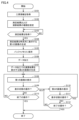
- FIG. 4 is a flow chart showing the processing executed by the processor of the monitoring device according to this embodiment.
- the processing steps shown in FIG. 4 (hereinafter abbreviated as “S”) are realized by the processor 211 of the monitoring device 200 executing the monitoring program 231 .
- the monitoring device 200 determines whether or not the tool information of the cutting tool 100 stored in the sensor module 120 provided in the cutting tool 100 has been received (S101).
- the tool information includes the serial number of the tool, the type of tool (turning tool/milling tool, etc.), the type of sensor used (strain sensor/acceleration sensor, etc.), the number of channels (CH) for each sensor, and the number of channels used. Information such as number, sampling rate, sensor gain, measurement range, battery voltage, and radio wave strength are included.
- the tool information is not limited to being acquired from the sensor module 120, and can be acquired from the machining control device 301, for example.
- the monitoring device 200 If it is determined that tool information has not been received (NO in S101), the monitoring device 200 returns the process to S101 and maintains the state of accepting tool information.
- the monitoring device 200 sets the types of measurement results and calculation results (S102). Specifically, the monitoring device 200 sets the display format (such as the unit of the vertical axis) of the measurement results to be displayed in chronological order according to the type of sensor used as the type of measurement results, or sets the number of channels (CH). Set the number of graphs to be displayed accordingly.
- the monitoring device 200 sets the processing content of data processing according to the type of sensor used as the type of the calculation result, and sets the calculation result to be expressed in a spatial coordinate system according to the number of channels (CH). or
- the monitoring device 200 determines whether or not the measurement results obtained by the sensor of the cutting tool 100 have been acquired (S103).
- the machining control device 301 controls the machine tool 300 according to the set machining conditions, and when the machining process of cutting the workpiece with the attached cutting tool 100 is started, the monitoring device 200 controls the machining process from the sensor module 120 .
- the monitoring device 200 When determining that the measurement results have not been acquired (NO in S103), the monitoring device 200 returns the process to S103 and maintains the acquisition state of the measurement results. On the other hand, when determining that the measurement results have been obtained (YES in S103), the monitoring device 200 generates a first image displaying the measurement results in chronological order (S104).
- the monitoring device 200 stores the measurement results in the buffer memory 210 in order to perform data processing on the measurement results (S105).
- the monitoring device 200 performs data processing on the measurement results held in the buffer memory 210 (S106).
- data processing for example, preprocessing, feature amount calculation, basic statistic calculation, and correlation processing). calculation.
- preprocessing for example, processing such as elimination and complementation of missing values, noise processing, FFT (Fast Fourier Transform) processing, vector transformation [magnitude, direction], dimension compression, etc. is performed.
- the calculation of the feature quantity includes calculation of cutting resistance of the cutting tool, torque of the cutting tool, and the like.
- arithmetic mean, geometric mean, trimmed mean, variance, standard deviation, skewness, kurtosis, median, maximum value, minimum value, etc. are calculated.
- correlation calculation for example, measurement results from a plurality of sensors are associated, and covariance, correlation coefficient, partial correlation coefficient, factor loading, principal component score, etc. are calculated.
- the data processing for the measurement results should include any one of the calculation of the feature amount, the calculation of the basic statistic, and the calculation of the correlation.
- the monitoring device 200 sets the type of calculation result based on the tool information received in S101 (S102), data processing for the measurement result is also changed according to the type of calculation result.
- the monitoring device 200 is set with the type of calculation result representing the cutting resistance in the X and Y directions in a spatial coordinate system, and from the measurement result of the strain sensor The cutting force in the X and Y directions is calculated, and data processing is performed to represent it in a two-dimensional spatial coordinate system.
- the monitoring device 200 generates a second image displaying the calculation result of the data processing (S107).
- FIG. 5 is a diagram showing an example of the first image displayed by the monitoring device according to this embodiment.
- the horizontal axis is time [seconds] and the vertical axis is strain [ ⁇ ].
- FIG. 5 shows the measurement results obtained from the four strain sensors 122 in chronological order.
- the measurement results of the four strain sensors 122 are simply arranged in the first image D1 shown in FIG. be. Therefore, the user switches the display screen of the display 214 to the second image that displays the calculation result obtained by performing data processing on the measurement result.
- a mode selection radio button is provided on the upper right side, and by performing an operation to switch the radio button from "time series waveform" to "cutting resistance” , the display screen of the display 214 is switched to the second image.
- the monitoring device 200 determines whether or not a display switching operation has been accepted (S109). When determining that the display switching operation has been received (YES in S109), the monitoring device 200 displays the second image on the display screen of the display 214 (S110).
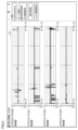
- FIG. 6 is a diagram showing an example of a second image displayed by the monitoring device according to this embodiment.
- FIG. 6 shows the time-series waveform of the cutting resistance of the cutting tool 100, the time-series waveform of the torque of the cutting tool 100, and the XY plot of the cutting resistance of the cutting tool 100, which are the calculation results of data processing, as a second image D2. is displayed.
- the horizontal axis is time [seconds] and the vertical axis is cutting resistance [N].
- the horizontal axis represents the cutting resistance [N] in the X-axis direction
- the vertical axis represents the cutting resistance [N] in the Y-axis direction.
- the monitoring device 200 monitors the X-axis direction cutting force, Y-axis direction cutting force and Calculate the torque experienced by 100.
- the monitoring device 200 divides the cutting force into components in the X-axis direction and components in the Y-axis direction while displaying images representing the calculated cutting force and torque in time series, and plots the cutting force two-dimensionally as an XY plot. display the image expressed in the spatial coordinate system of
- the monitoring device 200 displays the measurement result of the cutting state in real time in the first image D1 shown in FIG.
- the radio button for selection it is possible to instantly switch to the second image D2 shown in FIG.
- the user can grasp the cutting resistance and torque generated in the cutting tool 100 by looking at the second image displayed on the display screen of the display 214 when confirming the measurement result during the measurement.
- the user wants to see the first image D1 that displays the measurement results in chronological order, the user can switch the mode selection radio button on the upper right side of the screen from "cutting force" to "time series waveform”. good.
- the second image D2 shown in FIG. 6 it was explained that the time-series waveform of the cutting resistance of the cutting tool 100, the time-series waveform of the torque of the cutting tool 100, and the XY plot of the cutting resistance of the cutting tool 100 are displayed. It is not limited, and statistics such as average, variance, standard deviation, etc., which are calculation results in data processing, correlation coefficients of the cutting tool 100, and the like may be displayed. Since the monitoring device 200 holds measurement results for a fixed period in the buffer memory 210, it is possible to display graphs including past data.
- the monitoring device 200 determines whether or not a display switching operation has been accepted (S111). When determining that the display switching operation has been received (YES in S111), the monitoring apparatus 200 returns the process to S108 and displays the first image on the display screen of the display 214. FIG.
- the monitoring device 200 determines whether or not the operation to end the measurement has been accepted (S112). When determining that an operation to end the measurement has been received (YES in S112), the monitoring device 200 ends the process. When determining that an operation to end the measurement has not been received (NO in S112), the monitoring device 200 returns the process to S103 and maintains the acquisition state of the measurement result.
- the monitoring device 200 determines whether or not the operation to end the measurement has been accepted (S113). When determining that an operation to end the measurement has been received (YES in S113), the monitoring device 200 ends the process. When determining that an operation to end the measurement has not been received (NO in S113), the monitoring device 200 returns the process to S103 and maintains the acquisition state of the measurement result.
- the processor 211 performs data processing on the measurement results held in the buffer memory 210, and displays the first image displaying the acquired measurement results in time series and the calculation performed by the data processing. A second image displaying the result is displayed on the display screen of the display 214 .
- the processor 211 causes the display screen to display the first image that displays the measurement results in chronological order and the second image that displays the calculation results, so that the state of the cutting tool 100 can be determined more accurately. It is possible to provide the user with information that enables
- the processor 211 switches and displays the first image and the second image. This makes it possible to appropriately provide the user with information that enables more accurate determination of the state of the cutting tool 100 .
- the processor 211 selects the first image, the second image, and the first image and the second image as the images displayed on the display screen based on the received display switching operation. Switch to one of the images containing Thereby, the information required by the user can be displayed on the display screen at appropriate timing.
- the processor 211 acquires the tool information of the cutting tool 100, and changes the types of measurement results and calculation results to be displayed on the display screen based on the acquired tool information. Thereby, the information displayed on the display screen can be appropriately changed according to the type of cutting tool 100 .
- the processor 211 performs data processing that associates a plurality of acquired measurement results, and displays a calculation result in which the plurality of measurement results are associated in the second image. This makes it possible to provide the user with information that enables the state of the cutting tool 100 to be determined more accurately.
- the processor 211 expresses the calculation result associated with the plurality of measurement results in the spatial coordinate system and displays it in the second image. This makes it possible to provide the user with information that enables the state of the cutting tool 100 to be determined more accurately.
- the images are switched and displayed on the display screen of the display 214, the first image and the second image may be automatically switched, for example, at regular intervals.
- the display screen of the display 214 is switched between the first image showing the measurement results shown in FIG.
- the first image and the second image may be displayed on the same display screen. That is, in the present embodiment, the image displayed on the display screen is selected from among the first image, the second image, and the image including the first image and the second image by the user's display switching operation. You may display on the display 214 switching to either.
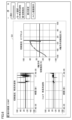
- FIG. 7 is a diagram showing an example of a third image displayed by the monitoring device according to this embodiment. In FIG. 7, the measurement results acquired from the two strain sensors 122 are displayed in chronological order, and an XY plot of the cutting resistance of the cutting tool 100 is displayed. That is, the third image D3 shown in FIG.
- the 7 includes the first image D1 displaying the measurement results in chronological order and the second image D2 displaying the calculation results of the data processing.
- the image D1 and the second image D2 can be displayed on the same display screen. Accordingly, it is possible to provide the user with information that enables a more accurate determination of the state of the cutting tool 100 without switching the displayed image.
- a "display setting" button is displayed in the upper right.
- the monitoring apparatus 200 accepts a user's operation of pressing the "display setting” button, the monitoring apparatus 200 changes the layout of the first image and the second image displayed on the display screen based on the accepted operation. good too. As a result, it is possible to display a screen that suits the user's taste, and to provide the user with information that enables more accurate determination of the state of the cutting tool 100 .
- the measurement result is an output value from a sensor such as a strain sensor, but it is not limited to this, and includes a value obtained by converting the output value from the sensor using a predetermined conversion formula.
- machining system 1 machining system, 2 machining condition management system, 210 buffer memory, 211 processor, 50 tool post, 215 input interface, 100 cutting tool, 110 cutting insert, 111 shank, 113A, 113B fixing member, 120 sensor module, 121 acceleration sensor , 122 strain sensor, 123 processing unit, 124 communication unit, 125 storage unit, 129 battery, 200 monitoring device, 201 wireless device, 212 communication device, 213 storage device, 214 display, 216 media reading device, 220 recording medium, 231 monitoring Program, 232 Machining conditions, 233 Measurement result, 300 Machine tool, 301 Machining control device.
Landscapes
- Engineering & Computer Science (AREA)
- Mechanical Engineering (AREA)
- Machine Tool Sensing Apparatuses (AREA)
- Numerical Control (AREA)
Priority Applications (2)
| Application Number | Priority Date | Filing Date | Title |
|---|---|---|---|
| JP2022529101A JP7160230B1 (ja) | 2021-10-18 | 2021-10-18 | 監視装置、監視方法、加工システム、およびプログラム |
| PCT/JP2021/038356 WO2023067642A1 (ja) | 2021-10-18 | 2021-10-18 | 監視装置、監視方法、加工システム、およびプログラム |
Applications Claiming Priority (1)
| Application Number | Priority Date | Filing Date | Title |
|---|---|---|---|
| PCT/JP2021/038356 WO2023067642A1 (ja) | 2021-10-18 | 2021-10-18 | 監視装置、監視方法、加工システム、およびプログラム |
Publications (1)
| Publication Number | Publication Date |
|---|---|
| WO2023067642A1 true WO2023067642A1 (ja) | 2023-04-27 |
Family
ID=83742517
Family Applications (1)
| Application Number | Title | Priority Date | Filing Date |
|---|---|---|---|
| PCT/JP2021/038356 Ceased WO2023067642A1 (ja) | 2021-10-18 | 2021-10-18 | 監視装置、監視方法、加工システム、およびプログラム |
Country Status (2)
| Country | Link |
|---|---|
| JP (1) | JP7160230B1 (https=) |
| WO (1) | WO2023067642A1 (https=) |
Cited By (1)
| Publication number | Priority date | Publication date | Assignee | Title |
|---|---|---|---|---|
| JP7537647B1 (ja) * | 2023-10-12 | 2024-08-21 | 住友電気工業株式会社 | 処理装置、処理システム、コンピュータプログラム、および処理方法 |
Families Citing this family (2)
| Publication number | Priority date | Publication date | Assignee | Title |
|---|---|---|---|---|
| JP7384321B1 (ja) * | 2022-11-07 | 2023-11-21 | 住友電気工業株式会社 | 処理装置、処理方法、システムおよびコンピュータプログラム |
| JP7796301B1 (ja) * | 2024-10-30 | 2026-01-08 | 住友電工ハードメタル株式会社 | 管理装置、管理装置の制御方法およびそれに用いられるプログラム、ならびに切削システム |
Citations (10)
| Publication number | Priority date | Publication date | Assignee | Title |
|---|---|---|---|---|
| JPH068106A (ja) * | 1991-06-28 | 1994-01-18 | Mamoru Mitsuishi | 適応制御システムおよび状態判定装置 |
| JP2012093983A (ja) * | 2010-10-27 | 2012-05-17 | Okuma Corp | 振動表示装置 |
| WO2013073436A1 (ja) * | 2011-11-15 | 2013-05-23 | 株式会社日立製作所 | 工作機械の切削力検出装置、切削力検出方法、加工異常検出方法、および加工条件制御システム |
| US20140216170A1 (en) * | 2013-02-05 | 2014-08-07 | Georgia Tech Research Corporation | Systems And Methods For Monitoring Cutting Forces In Peripheral End Milling |
| JP2015077658A (ja) * | 2013-10-17 | 2015-04-23 | 株式会社神戸製鋼所 | 状態計測装置及び状態計測システム |
| US20150261207A1 (en) * | 2014-03-11 | 2015-09-17 | Pro-Micron Gmbh & Co. Kg | Method for setting and/or monitoring operating parameters of a workpiece processing machine |
| WO2015194010A1 (ja) * | 2014-06-19 | 2015-12-23 | 株式会社牧野フライス製作所 | 工作機械の制御装置 |
| US20180117725A1 (en) * | 2015-04-13 | 2018-05-03 | Centre Technique Des Industries Mecaniques Et Du Decolletage | Method for monitoring a milling method |
| WO2018235170A1 (ja) * | 2017-06-20 | 2018-12-27 | ヤマザキマザック株式会社 | 工作機械管理システムおよび工作機械の管理方法 |
| WO2021049337A1 (ja) * | 2019-09-09 | 2021-03-18 | 住友電気工業株式会社 | 切削工具、切削システム、処理方法および処理プログラム |
-
2021
- 2021-10-18 JP JP2022529101A patent/JP7160230B1/ja active Active
- 2021-10-18 WO PCT/JP2021/038356 patent/WO2023067642A1/ja not_active Ceased
Patent Citations (10)
| Publication number | Priority date | Publication date | Assignee | Title |
|---|---|---|---|---|
| JPH068106A (ja) * | 1991-06-28 | 1994-01-18 | Mamoru Mitsuishi | 適応制御システムおよび状態判定装置 |
| JP2012093983A (ja) * | 2010-10-27 | 2012-05-17 | Okuma Corp | 振動表示装置 |
| WO2013073436A1 (ja) * | 2011-11-15 | 2013-05-23 | 株式会社日立製作所 | 工作機械の切削力検出装置、切削力検出方法、加工異常検出方法、および加工条件制御システム |
| US20140216170A1 (en) * | 2013-02-05 | 2014-08-07 | Georgia Tech Research Corporation | Systems And Methods For Monitoring Cutting Forces In Peripheral End Milling |
| JP2015077658A (ja) * | 2013-10-17 | 2015-04-23 | 株式会社神戸製鋼所 | 状態計測装置及び状態計測システム |
| US20150261207A1 (en) * | 2014-03-11 | 2015-09-17 | Pro-Micron Gmbh & Co. Kg | Method for setting and/or monitoring operating parameters of a workpiece processing machine |
| WO2015194010A1 (ja) * | 2014-06-19 | 2015-12-23 | 株式会社牧野フライス製作所 | 工作機械の制御装置 |
| US20180117725A1 (en) * | 2015-04-13 | 2018-05-03 | Centre Technique Des Industries Mecaniques Et Du Decolletage | Method for monitoring a milling method |
| WO2018235170A1 (ja) * | 2017-06-20 | 2018-12-27 | ヤマザキマザック株式会社 | 工作機械管理システムおよび工作機械の管理方法 |
| WO2021049337A1 (ja) * | 2019-09-09 | 2021-03-18 | 住友電気工業株式会社 | 切削工具、切削システム、処理方法および処理プログラム |
Cited By (2)
| Publication number | Priority date | Publication date | Assignee | Title |
|---|---|---|---|---|
| JP7537647B1 (ja) * | 2023-10-12 | 2024-08-21 | 住友電気工業株式会社 | 処理装置、処理システム、コンピュータプログラム、および処理方法 |
| WO2025079200A1 (ja) * | 2023-10-12 | 2025-04-17 | 住友電気工業株式会社 | 処理装置、処理システム、コンピュータプログラム、および処理方法 |
Also Published As
| Publication number | Publication date |
|---|---|
| JP7160230B1 (ja) | 2022-10-25 |
| JPWO2023067642A1 (https=) | 2023-04-27 |
Similar Documents
| Publication | Publication Date | Title |
|---|---|---|
| JP7160230B1 (ja) | 監視装置、監視方法、加工システム、およびプログラム | |
| JP7435576B2 (ja) | 切削システム、表示システム、処理装置、処理方法および処理プログラム | |
| US9186765B2 (en) | Monitoring method and monitoring apparatus for machine tool, and machine tool | |
| US10274932B2 (en) | Machining-information management device and tool-path generation device | |
| JP7032244B2 (ja) | 切削加工システム、及び情報処理装置 | |
| JP2022020722A5 (https=) | ||
| CN110091216B (zh) | 铣削噪声与铣削振动的监测及其相关性分析系统及方法 | |
| JP7151108B2 (ja) | 情報処理装置、情報処理方法およびプログラム | |
| JP7673761B2 (ja) | 表示装置、表示方法、加工システム、およびプログラム | |
| JP7099646B2 (ja) | 管理装置、表示処理方法および表示処理プログラム | |
| JP2020187488A (ja) | 状態監視装置及びプログラム | |
| JP2024110903A (ja) | 工場診断システム、データ収集送出装置、工場診断装置、プログラム | |
| US7383097B2 (en) | Method for managing machine tool data | |
| CN108363822A (zh) | 刀具刚性预测用于抑制切削颤振的装置及方法 | |
| WO2023243043A1 (ja) | 異常検知システム、異常検知装置、異常検知方法、及びコンピュータプログラム | |
| JP2022176183A (ja) | 加工条件管理システム、加工制御装置、加工システム、および加工プログラム | |
| JP2021117847A (ja) | 加工状態表示装置 | |
| CN111045391A (zh) | 加工信息记录装置、加工信息记录方法和计算机可读介质 | |
| JP7427938B2 (ja) | 診断装置、診断装置の制御方法およびプログラム | |
| JP7260077B1 (ja) | 切削システムおよび転削工具の状態判定方法 | |
| JP7796301B1 (ja) | 管理装置、管理装置の制御方法およびそれに用いられるプログラム、ならびに切削システム | |
| TW201827159A (zh) | 刀具剛性預測用於抑制切削顫振之裝置及方法 | |
| US20230091235A1 (en) | Information processing apparatus and information processing method | |
| WO2021241149A1 (ja) | 管理装置、表示処理方法および表示処理プログラム | |
| Roth et al. | Development of a cutting direction and sensor orientation independent monitoring technique for end-milling |
Legal Events
| Date | Code | Title | Description |
|---|---|---|---|
| WWE | Wipo information: entry into national phase |
Ref document number: 2022529101 Country of ref document: JP |
|
| 121 | Ep: the epo has been informed by wipo that ep was designated in this application |
Ref document number: 21961296 Country of ref document: EP Kind code of ref document: A1 |
|
| NENP | Non-entry into the national phase |
Ref country code: DE |
|
| 122 | Ep: pct application non-entry in european phase |
Ref document number: 21961296 Country of ref document: EP Kind code of ref document: A1 |