WO2023067642A1 - Monitoring device, monitoring method, machining system, and program - Google Patents
Monitoring device, monitoring method, machining system, and program Download PDFInfo
- Publication number
- WO2023067642A1 WO2023067642A1 PCT/JP2021/038356 JP2021038356W WO2023067642A1 WO 2023067642 A1 WO2023067642 A1 WO 2023067642A1 JP 2021038356 W JP2021038356 W JP 2021038356W WO 2023067642 A1 WO2023067642 A1 WO 2023067642A1
- Authority
- WO
- WIPO (PCT)
- Prior art keywords
- image
- measurement results
- unit
- tool
- monitoring device
- Prior art date
Links
- 238000003754 machining Methods 0.000 title claims abstract description 94
- 238000012806 monitoring device Methods 0.000 title claims abstract description 92
- 238000012544 monitoring process Methods 0.000 title claims description 32
- 238000000034 method Methods 0.000 title claims description 27
- 238000005259 measurement Methods 0.000 claims abstract description 129
- 238000012545 processing Methods 0.000 claims abstract description 115
- 230000015654 memory Effects 0.000 claims abstract description 41
- 238000005520 cutting process Methods 0.000 description 117
- 238000004891 communication Methods 0.000 description 17
- 238000003860 storage Methods 0.000 description 14
- 230000001133 acceleration Effects 0.000 description 12
- 238000010586 diagram Methods 0.000 description 12
- 230000008569 process Effects 0.000 description 12
- 230000006870 function Effects 0.000 description 5
- 238000003801 milling Methods 0.000 description 4
- 239000000463 material Substances 0.000 description 3
- 230000000694 effects Effects 0.000 description 2
- 238000012986 modification Methods 0.000 description 2
- 230000004048 modification Effects 0.000 description 2
- 238000007781 pre-processing Methods 0.000 description 2
- 238000005070 sampling Methods 0.000 description 2
- 239000007787 solid Substances 0.000 description 2
- 238000005219 brazing Methods 0.000 description 1
- 239000003990 capacitor Substances 0.000 description 1
- 230000008859 change Effects 0.000 description 1
- 238000006243 chemical reaction Methods 0.000 description 1
- 230000006835 compression Effects 0.000 description 1
- 238000007906 compression Methods 0.000 description 1
- 230000003247 decreasing effect Effects 0.000 description 1
- 238000006073 displacement reaction Methods 0.000 description 1
- 230000008030 elimination Effects 0.000 description 1
- 238000003379 elimination reaction Methods 0.000 description 1
- 238000005516 engineering process Methods 0.000 description 1
- 238000003825 pressing Methods 0.000 description 1
- 230000003068 static effect Effects 0.000 description 1
- 230000009466 transformation Effects 0.000 description 1
Images


Classifications
-
- B—PERFORMING OPERATIONS; TRANSPORTING
- B23—MACHINE TOOLS; METAL-WORKING NOT OTHERWISE PROVIDED FOR
- B23Q—DETAILS, COMPONENTS, OR ACCESSORIES FOR MACHINE TOOLS, e.g. ARRANGEMENTS FOR COPYING OR CONTROLLING; MACHINE TOOLS IN GENERAL CHARACTERISED BY THE CONSTRUCTION OF PARTICULAR DETAILS OR COMPONENTS; COMBINATIONS OR ASSOCIATIONS OF METAL-WORKING MACHINES, NOT DIRECTED TO A PARTICULAR RESULT
- B23Q17/00—Arrangements for observing, indicating or measuring on machine tools
- B23Q17/09—Arrangements for observing, indicating or measuring on machine tools for indicating or measuring cutting pressure or for determining cutting-tool condition, e.g. cutting ability, load on tool
Definitions
- the present disclosure relates to monitoring devices, monitoring methods, processing systems, and programs.
- Patent Document 1 Japanese Patent Publication No. 2018-534680 discloses a combined system comprising a control system and a monitoring system.
- the monitoring system is configured to provide at least an input configured to receive data from the control system or tool and an output for providing the received data as an input signal to a programmable logic controller of the control system. and an output section.
- a monitoring device monitors the state of a processing tool.
- the monitoring device includes an acquisition unit that acquires measurement results from at least one sensor attached to the processing tool, a memory that holds measurement results for a predetermined period after acquisition by the acquisition unit, and measurement results held in the memory. , a first image displaying the measurement results obtained by the obtaining unit in chronological order, and a second image displaying the results of the data processing performed by the calculating unit, and an image processing unit for displaying on a display screen.
- a machining system includes a machine tool that performs machining using a machining tool having at least one sensor, and a monitoring device that monitors the state of the machining tool used in the machine tool.
- the monitoring device includes an acquisition unit that acquires the measurement results from the sensor, a memory that holds the measurement results for a predetermined period after the acquisition by the acquisition unit, and a calculation unit that processes the measurement results held in the memory. and an image processing unit for displaying on a display screen a first image displaying the measurement results obtained by the obtaining unit in chronological order and a second image displaying the calculation results obtained by data processing performed by the calculation unit. , including.
- a monitoring method is a method for monitoring the state of a processing tool.
- the monitoring method includes the steps of acquiring measurement results from at least one sensor attached to the machining tool, storing the measurement results for a predetermined period after acquisition in a memory, and and displaying, on a display screen, a first image displaying the acquired measurement results in chronological order and a second image displaying the calculation results of the data processing. include.
- a program according to the present disclosure is executed by a monitoring device that monitors the state of the machining tool.
- the program includes steps of acquiring measurement results from at least one sensor attached to the machining tool, storing the measurement results for a predetermined period after acquisition in a memory, a step of performing data processing; and a step of displaying, on a display screen, a first image displaying the acquired measurement results in time series and a second image displaying the calculation results of the data processing.
- FIG. 1 is a diagram showing the configuration of a processing system according to this embodiment.
- FIG. 2 is a diagram showing the configuration of the sensor module according to this embodiment.
- FIG. 3 is a diagram showing the configuration of the monitoring device according to this embodiment.
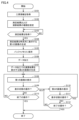
- FIG. 4 is a flow chart showing the processing executed by the processor of the monitoring device according to this embodiment.
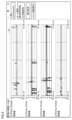
- FIG. 5 is a diagram showing an example of the first image displayed by the monitoring device according to this embodiment.
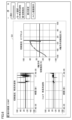
- FIG. 6 is a diagram showing an example of a second image displayed by the monitoring device according to this embodiment.
- FIG. 7 is a diagram showing an example of a third image displayed by the monitoring device according to this embodiment.
- Patent Document 1 describes a technique for monitoring the state of a machining tool. A technology capable of providing the user with the information necessary for
- An object of the present disclosure is to provide a monitoring device, monitoring method, machining system, and program capable of monitoring the state of a machining tool during machining.
- a monitoring device monitors the state of a machining tool.
- the monitoring device includes an acquisition unit that acquires measurement results from at least one sensor attached to the processing tool, a memory that holds measurement results for a predetermined period after acquisition by the acquisition unit, and measurement results held in the memory. , a first image displaying the measurement results obtained by the obtaining unit in chronological order, and a second image displaying the results of the data processing performed by the calculating unit, and an image processing unit for displaying on a display screen.
- the image processing unit displays the first image displaying the measurement results in chronological order and the second image displaying the calculation results on the display screen, so that the state of the machining tool can be determined more accurately.
- the user can be provided with information that enables
- the image processing unit switches and displays the first image and the second image.
- the image processing unit displays the first image and the second image on the same display screen.
- the information can be displayed so that the user can easily view the information so that the state of the machining tool can be determined more accurately.
- an input unit that receives a user's operation is further provided, and the image processing unit selects an image to be displayed on the display screen as a first image, a second and an image including a first image and a second image.
- an input unit that receives a user's operation is further provided, and the image processing unit changes the layout of the first image and the second image displayed on the display screen based on the operation received by the input unit. .
- the user can customize the display screen so that the required information can be displayed.
- the acquisition unit acquires tool information of the processing tool
- the image processing unit changes types of measurement results and calculation results to be displayed on the display screen based on the tool information acquired by the acquisition unit.
- the calculation unit performs data processing to associate the plurality of measurement results acquired by the acquisition unit, and the image processing unit performs A calculation result associated with a plurality of measurement results is displayed in the second image.
- the image processing unit expresses the calculation result in which the plurality of measurement results are associated by the calculation unit in a spatial coordinate system and displays it in the second image.
- a machining system includes a machine tool that performs machining using a machining tool having at least one sensor, and a monitoring device that monitors the state of the machining tool used in the machine tool.
- the monitoring device includes an acquisition unit that acquires the measurement results from the sensor, a memory that holds the measurement results for a predetermined period after the acquisition by the acquisition unit, and a calculation unit that processes the measurement results held in the memory. and an image processing unit for displaying on a display screen a first image displaying the measurement results obtained by the obtaining unit in chronological order and a second image displaying the calculation results obtained by data processing performed by the calculation unit. , including.
- the image processing unit displays the first image displaying the measurement results in chronological order and the second image displaying the calculation results on the display screen, so that the state of the machining tool can be determined more accurately.
- the user can be provided with information that enables
- a monitoring method is a method for monitoring the state of a machining tool.
- the monitoring method includes the steps of acquiring measurement results from at least one sensor attached to the machining tool, storing the measurement results for a predetermined period after acquisition in a memory, and and displaying, on a display screen, a first image displaying the acquired measurement results in chronological order and a second image displaying the calculation results of the data processing. include.
- the first image displaying the measurement results in chronological order and the second image displaying the calculation results are displayed on the display screen, so that the state of the machining tool can be determined more accurately. It is possible to provide the user with information that enables
- a program according to the present disclosure is executed by a monitoring device that monitors the state of the machining tool.
- the program includes steps of acquiring measurement results from at least one sensor attached to the machining tool, storing the measurement results for a predetermined period after acquisition in a memory, a step of performing data processing; and a step of displaying, on a display screen, a first image displaying the acquired measurement results in time series and a second image displaying the calculation results of the data processing.
- the program displays the first image displaying the measurement results in chronological order and the second image displaying the calculation results on the display screen, so that the state of the machining tool can be determined more accurately. It is possible to provide the user with information that enables
- FIG. 1 ⁇ Configuration of processing system> The configuration of a processing system 1 according to the present embodiment will be described with reference to FIGS. 1 to 3.
- FIG. 1 ⁇ Configuration of processing system> The configuration of a processing system 1 according to the present embodiment will be described with reference to FIGS. 1 to 3.
- FIG. 1 ⁇ Configuration of processing system> The configuration of a processing system 1 according to the present embodiment will be described with reference to FIGS. 1 to 3.
- FIG. 1 is a diagram showing the configuration of a processing system according to this embodiment.
- the machining system 1 includes a cutting tool 100 , a monitoring device 200 , a wireless device 201 , a machine tool 300 and a machining control device 301 .
- the cutting tool 100 is attached to the machine tool 300.
- the cutting tool 100 is an example of a processing tool, and is not limited to a processing tool used for cutting as long as it is a processing tool attached to the machine tool 300, and may be a processing tool widely used for processing.
- the machining control device 301 controls the machine tool 300 according to the set machining path information and cutting conditions, and cuts the workpiece with the attached cutting tool 100 .
- the machining pass information includes information such as the coordinate position of the cutting tool 100, the trajectory of the cutting tool 100, and the number of passes.
- the cutting conditions include information such as the depth of cut of the cutting tool 100, the feed (feed rate) of the cutting tool 100, the cutting speed of the cutting tool 100, and the like.
- machining pass information and cutting conditions are collectively referred to as machining conditions, and hereinafter, machining conditions include at least one of machining pass information and cutting conditions.
- the machining path is path information of a tool in a machine tool when machining a workpiece (cut material).
- Conditions for distinguishing between one machining pass and another machining pass include, for example, a) when the machining location of the workpiece such as an end face or counterbore changes during machining of the workpiece, and b) the same machining path.
- a machining pass can also be defined as a machining unit in which at least one of parameters such as the coordinate position of the cutting tool 100, the trajectory of the cutting tool 100, and the number of repetitions is different.
- the cutting tool 100 is provided with the sensor module 120, and the load of the cutting tool 100 can be measured by the sensor. Therefore, the monitoring device 200 can monitor the load of the cutting tool 100 based on the information received from the sensor module 120.
- FIG. 1 by monitoring the load of the cutting tool 100 with the monitoring device 200, the cutting tool 100 is monitored to see if an excessive load is applied to the cutting tool 100 such that the machining accuracy is lowered or the cutting tool 100 is damaged. can do.
- the machining system 1 transmits load information (measurement result) of the cutting tool 100 measured by the sensor module 120 to the wireless device 201 as a wireless signal, and transmits load information of the cutting tool 100 received by the wireless device 201. is temporarily held in the buffer memory 210 by the monitoring device 200 .
- a general monitoring device simply displays the received cutting tool load information in chronological order. Therefore, when the load on the cutting tool displayed in chronological order changes significantly, the user can determine that the machining accuracy has decreased or the cutting tool 100 has been damaged. Simply displaying information on the load on the cutting tool in chronological order does not allow more accurate determination of the state of the machining tool.
- the monitoring device 200 performs data processing on the load information of the cutting tool 100 held in the buffer memory 210, and displays an image (first image) in chronological order of the load of the cutting tool 100 and data An image (second image) displaying the processed calculation result is displayed on the display screen of the display 214 .
- the monitoring device 200 processes small changes that would be overlooked by simply displaying the load information of the cutting tool in chronological order by processing the data into information recognizable by the user and displaying it. Tool condition can be determined more accurately.
- the machining system 1 can be realized by combining the existing machine tool 300 with the cutting tool 100 incorporating the sensor module 120 , the monitoring device 200 , and the wireless device 201 . That is, by preparing the machining tool monitoring system 2 configured to include the cutting tool 100, the monitoring device 200, and the wireless device 201, and incorporating the machining tool monitoring system 2 into the existing machine tool 300 later, System 1 can be realized.
- the machining system 1 and the machining tool monitoring system 2 shown in FIG. 1 are merely examples, and may have other configurations.
- the processing system 1 is not limited to the configuration including one cutting tool 100 , and may be configured to include a plurality of cutting tools 100 .
- the processing system 1 is not limited to the configuration including one monitoring device 200 , and may be configured to include a plurality of monitoring devices 200 .
- the cutting tool 100 is sandwiched from above and below by the tool post 50 of the machine tool 300 and fixed.
- the cutting tool 100 is, for example, a turning tool used for machining a rotating workpiece, and is attached to a machine tool 300 such as a lathe.
- the part of the cutting tool 100 that cuts the workpiece is a cutting insert 110 having a cutting edge, and the cutting insert 110 can be replaced when worn or damaged.
- the cutting tool 100 includes a cutting insert 110 and a shank 111 that holds the cutting insert 110 . That is, the cutting tool 100 is a so-called throwaway tool.
- the cutting insert 110 is held on the shank 111 by fixing members 113A and 113B.
- the cutting tool 100 may have a cutting edge itself instead of not including the fixing members 113A and 113B. That is, cutting tool 100 may be a solid bit or a brazing bit.
- the cutting tool 100 may be a milling tool attached to a machine tool such as a milling machine for a machining method in which the tool rotates on a fixed workpiece, instead of a turning tool. More specifically, the cutting tool 100 may be a milling cutter or drill to which a cutting insert 110 can be attached, or an end mill or drill that does not use cutting inserts.
- FIG. 2 is a diagram showing the configuration of the sensor module according to this embodiment.
- Sensor module 120 includes acceleration sensor 121 , strain sensor 122 , processing unit 123 , communication unit 124 , storage unit 125 and battery 129 .
- Sensor module 120 is activated, for example, by a user's operation.
- the processing unit 123 is implemented by a processor such as a CPU (Central Processing Unit) and a DSP (Digital Signal Processor).
- the processor may be a hardware circuit based on ASIC (Application Specific Integrated Circuit).
- the communication unit 124 is implemented by a communication circuit such as a communication IC (Integrated Circuit).
- Storage unit 125 is, for example, a non-volatile memory.
- the battery 129 is, for example, a power storage device including a primary battery, a secondary battery, a solar battery, a capacitor, or the like, and may have a non-contact power supply function. Battery 129 supplies power to each circuit of acceleration sensor 121 , strain sensor 122 , processing unit 123 and communication unit 124 .
- the acceleration sensor 121 and the strain sensor 122 are provided near the cutting edge of the cutting tool 100, for example.
- the sensor module 120 is not limited to the configuration including one acceleration sensor 121 , and may be configured to include a plurality of acceleration sensors 121 .
- the sensor module 120 is not limited to the configuration including one strain sensor 122 , and may be configured to include a plurality of strain sensors 122 .
- the sensor module 120 is configured to include other sensors such as a pressure sensor and a displacement sensor in place of at least one of the acceleration sensor 121 and strain sensor 122 or in addition to the acceleration sensor 121 and strain sensor 122. may
- the processing unit 123 generates measurement information indicating the measured value of the acceleration sensor 121 and the measured value of the strain sensor 122 .
- the processing unit 123 AD Analog Digital converts the analog signals received from the acceleration sensor 121 and the strain sensor 122 at sampling timings according to a predetermined cycle, and generates sensor measurement values that are converted digital values. .
- the processing unit 123 outputs measurement information including the measured value of the sensor to the communication unit 124.
- the communication unit 124 transmits the packet containing the measurement information received from the processing unit 123 to the monitoring device 200 via the wireless device 201 .
- FIG. 3 is a diagram showing the configuration of the monitoring device according to this embodiment.
- monitoring device 200 includes buffer memory 210 , processor 211 (computing unit), communication device 212 , storage device 213 , display 214 , input interface 215 and media reading device 216 .
- the buffer memory 210 holds the measurement results obtained from the sensor module 120 for a predetermined period (for example, 30 seconds) after obtaining them.
- it is a memory for temporarily holding the measurement results acquired from the sensor module 120, and is a volatile memory such as DRAM (Dynamic Random Access Memory) and SRAM (Static Random Access Memory). Therefore, every time the buffer memory 210 holds a new measurement result, the measurement result after a predetermined period of time has passed since it was acquired is deleted.
- the processor 211 is a computing entity that executes various processes related to the monitoring device 200 by executing various programs (for example, a monitoring program 231 to be described later).
- the processor 211 is composed of processors such as a CPU and a DSP, for example.
- the processor 211 may be configured with a processing circuit.
- the communication device 212 establishes communication with each of the processing control device 301 and the sensor module 120 via communication means such as a network, and exchanges data (information) with each of the processing control device 301 and the sensor module 120. send and receive Therefore, the communication device 212 has a function as an acquisition unit that acquires the load information of the cutting tool 100 from the sensor module 120 .
- the storage device 213 is composed of non-volatile memories such as ROM (Read Only Memory), SSD (Solid State Drive), and HDD (Hard Disk Drive).
- the storage device 213 stores a monitoring program 231, machining conditions 232 of the machine tool acquired from the machining control device 301, and measurement results 233 measured by sensors.
- the measurement results 233 stored in the storage device 213 are all measurement results from the start of machining to the end of machining, and are stored as data files for each machining.
- the measurement results 233 stored in the storage device 213 may be the measurement results via the buffer memory 210 or the measurement results directly transmitted from the sensor module 120 .
- the machining conditions 232 of the machine tool and the measurement results 233 measured by the sensor are stored in a storage device (for example, a server) connected directly or via a network to the monitoring device 200 instead of the storage device 213. good too. If the monitoring device 200 does not acquire the machining conditions 232 of the machine tool from the machining control device 301 , the machining conditions 232 are not stored in the storage device 213 .
- a storage device for example, a server
- the monitoring program 231 is a program that is executed by the processor 211 (calculation unit), performs data processing on the measurement results measured by the sensor, and displays the measurement results and the calculation results of the data processing on the display 214 .
- the processor 211 executes the processing of the flowchart of FIG. 4, which will be described later.
- the media reading device 216 accepts recording media 220 for recording various programs and data, and reads the programs and data from the recording media 220 .
- Examples of the recording medium 220 include a CD (Compact Disk), an SD card (Secure Digital card), a USB memory (Universal Serial Bus memory), and the like.
- the media reading device 216 reads the monitoring program 231 stored in the recording medium 220 and causes the storage device 213 to store the monitoring program 231 .
- the display 214 is a device that displays an image processed by the processor 211 on a display screen.
- the display 214 displays, for example, a first image that displays the measurement results in chronological order and a second image that displays the calculation results of data processing.
- the display 214 displays various information screens to the user in addition to the images displaying the measurement results in chronological order.
- an image processing processor GPU: Graphics Processing Unit
- the processor 211 or the image processor has a function as an image processing unit that displays an image on the display screen of the display 214 .
- the image may be transmitted to an external device and displayed on the display screen of the external device (for example, an external monitor).
- a configuration including the communication device 212 in the image processor functions as an image processing unit.
- the input interface 215 is an interface that accepts data input to the monitoring device 200, and is connected to input devices such as a keyboard and a mouse that can be operated by the user. For example, the user can use the input device to cause the input interface 215 to accept user operations such as display switching operations and image layout changing operations. That is, the input interface 215 has a function as an input unit that receives user's operations.
- the wireless device 201 is connected to the monitoring device 200 by wire, for example.
- Wireless device 201 is, for example, an access point.
- the wireless device 201 acquires a wireless signal received from the cutting tool 100 and relays it to the monitoring device 200 .
- the wireless device 201 is, for example, ZigBee (registered trademark) conforming to IEEE 802.15.4, Bluetooth (registered trademark) conforming to IEEE 802.15.1, and UWB (Ultra-Wide Wideband) conforming to IEEE 802.15.3a.
- the cutting tool 100 communicates with the cutting tool 100 by radio using a communication protocol such as Band). Communication protocols other than those described above may be used between the cutting tool 100 and the wireless device 201 .
- FIG. 4 is a flow chart showing the processing executed by the processor of the monitoring device according to this embodiment.
- the processing steps shown in FIG. 4 (hereinafter abbreviated as “S”) are realized by the processor 211 of the monitoring device 200 executing the monitoring program 231 .
- the monitoring device 200 determines whether or not the tool information of the cutting tool 100 stored in the sensor module 120 provided in the cutting tool 100 has been received (S101).
- the tool information includes the serial number of the tool, the type of tool (turning tool/milling tool, etc.), the type of sensor used (strain sensor/acceleration sensor, etc.), the number of channels (CH) for each sensor, and the number of channels used. Information such as number, sampling rate, sensor gain, measurement range, battery voltage, and radio wave strength are included.
- the tool information is not limited to being acquired from the sensor module 120, and can be acquired from the machining control device 301, for example.
- the monitoring device 200 If it is determined that tool information has not been received (NO in S101), the monitoring device 200 returns the process to S101 and maintains the state of accepting tool information.
- the monitoring device 200 sets the types of measurement results and calculation results (S102). Specifically, the monitoring device 200 sets the display format (such as the unit of the vertical axis) of the measurement results to be displayed in chronological order according to the type of sensor used as the type of measurement results, or sets the number of channels (CH). Set the number of graphs to be displayed accordingly.
- the monitoring device 200 sets the processing content of data processing according to the type of sensor used as the type of the calculation result, and sets the calculation result to be expressed in a spatial coordinate system according to the number of channels (CH). or
- the monitoring device 200 determines whether or not the measurement results obtained by the sensor of the cutting tool 100 have been acquired (S103).
- the machining control device 301 controls the machine tool 300 according to the set machining conditions, and when the machining process of cutting the workpiece with the attached cutting tool 100 is started, the monitoring device 200 controls the machining process from the sensor module 120 .
- the monitoring device 200 When determining that the measurement results have not been acquired (NO in S103), the monitoring device 200 returns the process to S103 and maintains the acquisition state of the measurement results. On the other hand, when determining that the measurement results have been obtained (YES in S103), the monitoring device 200 generates a first image displaying the measurement results in chronological order (S104).
- the monitoring device 200 stores the measurement results in the buffer memory 210 in order to perform data processing on the measurement results (S105).
- the monitoring device 200 performs data processing on the measurement results held in the buffer memory 210 (S106).
- data processing for example, preprocessing, feature amount calculation, basic statistic calculation, and correlation processing). calculation.
- preprocessing for example, processing such as elimination and complementation of missing values, noise processing, FFT (Fast Fourier Transform) processing, vector transformation [magnitude, direction], dimension compression, etc. is performed.
- the calculation of the feature quantity includes calculation of cutting resistance of the cutting tool, torque of the cutting tool, and the like.
- arithmetic mean, geometric mean, trimmed mean, variance, standard deviation, skewness, kurtosis, median, maximum value, minimum value, etc. are calculated.
- correlation calculation for example, measurement results from a plurality of sensors are associated, and covariance, correlation coefficient, partial correlation coefficient, factor loading, principal component score, etc. are calculated.
- the data processing for the measurement results should include any one of the calculation of the feature amount, the calculation of the basic statistic, and the calculation of the correlation.
- the monitoring device 200 sets the type of calculation result based on the tool information received in S101 (S102), data processing for the measurement result is also changed according to the type of calculation result.
- the monitoring device 200 is set with the type of calculation result representing the cutting resistance in the X and Y directions in a spatial coordinate system, and from the measurement result of the strain sensor The cutting force in the X and Y directions is calculated, and data processing is performed to represent it in a two-dimensional spatial coordinate system.
- the monitoring device 200 generates a second image displaying the calculation result of the data processing (S107).
- FIG. 5 is a diagram showing an example of the first image displayed by the monitoring device according to this embodiment.
- the horizontal axis is time [seconds] and the vertical axis is strain [ ⁇ ].
- FIG. 5 shows the measurement results obtained from the four strain sensors 122 in chronological order.
- the measurement results of the four strain sensors 122 are simply arranged in the first image D1 shown in FIG. be. Therefore, the user switches the display screen of the display 214 to the second image that displays the calculation result obtained by performing data processing on the measurement result.
- a mode selection radio button is provided on the upper right side, and by performing an operation to switch the radio button from "time series waveform" to "cutting resistance” , the display screen of the display 214 is switched to the second image.
- the monitoring device 200 determines whether or not a display switching operation has been accepted (S109). When determining that the display switching operation has been received (YES in S109), the monitoring device 200 displays the second image on the display screen of the display 214 (S110).
- FIG. 6 is a diagram showing an example of a second image displayed by the monitoring device according to this embodiment.
- FIG. 6 shows the time-series waveform of the cutting resistance of the cutting tool 100, the time-series waveform of the torque of the cutting tool 100, and the XY plot of the cutting resistance of the cutting tool 100, which are the calculation results of data processing, as a second image D2. is displayed.
- the horizontal axis is time [seconds] and the vertical axis is cutting resistance [N].
- the horizontal axis represents the cutting resistance [N] in the X-axis direction
- the vertical axis represents the cutting resistance [N] in the Y-axis direction.
- the monitoring device 200 monitors the X-axis direction cutting force, Y-axis direction cutting force and Calculate the torque experienced by 100.
- the monitoring device 200 divides the cutting force into components in the X-axis direction and components in the Y-axis direction while displaying images representing the calculated cutting force and torque in time series, and plots the cutting force two-dimensionally as an XY plot. display the image expressed in the spatial coordinate system of
- the monitoring device 200 displays the measurement result of the cutting state in real time in the first image D1 shown in FIG.
- the radio button for selection it is possible to instantly switch to the second image D2 shown in FIG.
- the user can grasp the cutting resistance and torque generated in the cutting tool 100 by looking at the second image displayed on the display screen of the display 214 when confirming the measurement result during the measurement.
- the user wants to see the first image D1 that displays the measurement results in chronological order, the user can switch the mode selection radio button on the upper right side of the screen from "cutting force" to "time series waveform”. good.
- the second image D2 shown in FIG. 6 it was explained that the time-series waveform of the cutting resistance of the cutting tool 100, the time-series waveform of the torque of the cutting tool 100, and the XY plot of the cutting resistance of the cutting tool 100 are displayed. It is not limited, and statistics such as average, variance, standard deviation, etc., which are calculation results in data processing, correlation coefficients of the cutting tool 100, and the like may be displayed. Since the monitoring device 200 holds measurement results for a fixed period in the buffer memory 210, it is possible to display graphs including past data.
- the monitoring device 200 determines whether or not a display switching operation has been accepted (S111). When determining that the display switching operation has been received (YES in S111), the monitoring apparatus 200 returns the process to S108 and displays the first image on the display screen of the display 214. FIG.
- the monitoring device 200 determines whether or not the operation to end the measurement has been accepted (S112). When determining that an operation to end the measurement has been received (YES in S112), the monitoring device 200 ends the process. When determining that an operation to end the measurement has not been received (NO in S112), the monitoring device 200 returns the process to S103 and maintains the acquisition state of the measurement result.
- the monitoring device 200 determines whether or not the operation to end the measurement has been accepted (S113). When determining that an operation to end the measurement has been received (YES in S113), the monitoring device 200 ends the process. When determining that an operation to end the measurement has not been received (NO in S113), the monitoring device 200 returns the process to S103 and maintains the acquisition state of the measurement result.
- the processor 211 performs data processing on the measurement results held in the buffer memory 210, and displays the first image displaying the acquired measurement results in time series and the calculation performed by the data processing. A second image displaying the result is displayed on the display screen of the display 214 .
- the processor 211 causes the display screen to display the first image that displays the measurement results in chronological order and the second image that displays the calculation results, so that the state of the cutting tool 100 can be determined more accurately. It is possible to provide the user with information that enables
- the processor 211 switches and displays the first image and the second image. This makes it possible to appropriately provide the user with information that enables more accurate determination of the state of the cutting tool 100 .
- the processor 211 selects the first image, the second image, and the first image and the second image as the images displayed on the display screen based on the received display switching operation. Switch to one of the images containing Thereby, the information required by the user can be displayed on the display screen at appropriate timing.
- the processor 211 acquires the tool information of the cutting tool 100, and changes the types of measurement results and calculation results to be displayed on the display screen based on the acquired tool information. Thereby, the information displayed on the display screen can be appropriately changed according to the type of cutting tool 100 .
- the processor 211 performs data processing that associates a plurality of acquired measurement results, and displays a calculation result in which the plurality of measurement results are associated in the second image. This makes it possible to provide the user with information that enables the state of the cutting tool 100 to be determined more accurately.
- the processor 211 expresses the calculation result associated with the plurality of measurement results in the spatial coordinate system and displays it in the second image. This makes it possible to provide the user with information that enables the state of the cutting tool 100 to be determined more accurately.
- the images are switched and displayed on the display screen of the display 214, the first image and the second image may be automatically switched, for example, at regular intervals.
- the display screen of the display 214 is switched between the first image showing the measurement results shown in FIG.
- the first image and the second image may be displayed on the same display screen. That is, in the present embodiment, the image displayed on the display screen is selected from among the first image, the second image, and the image including the first image and the second image by the user's display switching operation. You may display on the display 214 switching to either.
- FIG. 7 is a diagram showing an example of a third image displayed by the monitoring device according to this embodiment. In FIG. 7, the measurement results acquired from the two strain sensors 122 are displayed in chronological order, and an XY plot of the cutting resistance of the cutting tool 100 is displayed. That is, the third image D3 shown in FIG.
- the 7 includes the first image D1 displaying the measurement results in chronological order and the second image D2 displaying the calculation results of the data processing.
- the image D1 and the second image D2 can be displayed on the same display screen. Accordingly, it is possible to provide the user with information that enables a more accurate determination of the state of the cutting tool 100 without switching the displayed image.
- a "display setting" button is displayed in the upper right.
- the monitoring apparatus 200 accepts a user's operation of pressing the "display setting” button, the monitoring apparatus 200 changes the layout of the first image and the second image displayed on the display screen based on the accepted operation. good too. As a result, it is possible to display a screen that suits the user's taste, and to provide the user with information that enables more accurate determination of the state of the cutting tool 100 .
- the measurement result is an output value from a sensor such as a strain sensor, but it is not limited to this, and includes a value obtained by converting the output value from the sensor using a predetermined conversion formula.
- machining system 1 machining system, 2 machining condition management system, 210 buffer memory, 211 processor, 50 tool post, 215 input interface, 100 cutting tool, 110 cutting insert, 111 shank, 113A, 113B fixing member, 120 sensor module, 121 acceleration sensor , 122 strain sensor, 123 processing unit, 124 communication unit, 125 storage unit, 129 battery, 200 monitoring device, 201 wireless device, 212 communication device, 213 storage device, 214 display, 216 media reading device, 220 recording medium, 231 monitoring Program, 232 Machining conditions, 233 Measurement result, 300 Machine tool, 301 Machining control device.
Abstract
A monitoring device according to the present disclosure monitors the state of a machining tool. The monitoring device comprises: an acquisition unit that acquires measurement results from at least one sensor fitted to a machining tool; memory that stores the measurement results of a prescribed time period once acquired by the acquisition unit; a computation unit that performs data processing of the measurement results stored in the memory; and an image processing unit that displays, on a display screen, a first image displaying the measurement results acquired by the acquisition unit in time-series, and a second image displaying computation results obtained as a result of the data processing performed by the computation unit.
Description
本開示は、監視装置、監視方法、加工システム、およびプログラムに関する。
The present disclosure relates to monitoring devices, monitoring methods, processing systems, and programs.
特許文献1(特表2018-534680号公報)には、制御システムおよびモニタリングシステムを備える、組み合わせシステムが開示されている。当該モニタリングシステムは、少なくとも制御システムまたは工具からデータを受信するように構成された入力部と、受信したデータを制御システムのプログラマブル論理制御部への入力信号として与えられる出力を提供するように構成された出力部とを備えている。
Patent Document 1 (Japanese Patent Publication No. 2018-534680) discloses a combined system comprising a control system and a monitoring system. The monitoring system is configured to provide at least an input configured to receive data from the control system or tool and an output for providing the received data as an input signal to a programmable logic controller of the control system. and an output section.
本開示に係る監視装置は、加工工具の状態を監視する。監視装置は、加工工具に装着された少なくとも1つのセンサから測定結果を取得する取得部と、取得部で取得してから所定の期間の測定結果を保持するメモリと、メモリに保持された測定結果に対してデータ加工を行う演算部と、取得部で取得した測定結果を時系列に表示する第1の画像と、演算部でデータ加工を行った演算結果を表示する第2の画像とを、表示画面に表示させる画像処理部と、を備える。
A monitoring device according to the present disclosure monitors the state of a processing tool. The monitoring device includes an acquisition unit that acquires measurement results from at least one sensor attached to the processing tool, a memory that holds measurement results for a predetermined period after acquisition by the acquisition unit, and measurement results held in the memory. , a first image displaying the measurement results obtained by the obtaining unit in chronological order, and a second image displaying the results of the data processing performed by the calculating unit, and an image processing unit for displaying on a display screen.
本開示に係る加工システムは、少なくとも1つのセンサを有する加工工具を用いて加工する工作機械と、工作機械に用いる加工工具の状態を監視する監視装置とを備える。監視装置は、センサから測定結果を取得する取得部と、取得部で取得してから所定の期間の測定結果を保持するメモリと、メモリに保持された測定結果に対してデータ加工を行う演算部と、取得部で取得した測定結果を時系列に表示する第1の画像と、演算部でデータ加工を行った演算結果を表示する第2の画像とを、表示画面に表示させる画像処理部と、を含む。
A machining system according to the present disclosure includes a machine tool that performs machining using a machining tool having at least one sensor, and a monitoring device that monitors the state of the machining tool used in the machine tool. The monitoring device includes an acquisition unit that acquires the measurement results from the sensor, a memory that holds the measurement results for a predetermined period after the acquisition by the acquisition unit, and a calculation unit that processes the measurement results held in the memory. and an image processing unit for displaying on a display screen a first image displaying the measurement results obtained by the obtaining unit in chronological order and a second image displaying the calculation results obtained by data processing performed by the calculation unit. ,including.
本開示に係る監視方法は、加工工具の状態を監視する方法である。監視方法は、加工工具に装着された少なくとも1つのセンサから測定結果を取得するステップと、取得してから所定の期間の測定結果をメモリに保存するステップと、メモリに保持された測定結果に対してデータ加工を行うステップと、取得した測定結果を時系列に表示する第1の画像と、データ加工を行った演算結果を表示する第2の画像とを、表示画面に表示させるステップと、を含む。
A monitoring method according to the present disclosure is a method for monitoring the state of a processing tool. The monitoring method includes the steps of acquiring measurement results from at least one sensor attached to the machining tool, storing the measurement results for a predetermined period after acquisition in a memory, and and displaying, on a display screen, a first image displaying the acquired measurement results in chronological order and a second image displaying the calculation results of the data processing. include.
本開示に係るプログラムは、加工工具の状態を監視する監視装置で実行される。プログラムは、加工工具に装着された少なくとも1つのセンサから測定結果を取得するステップと、取得してから所定の期間の測定結果をメモリに保存するステップと、メモリに保持された測定結果に対してデータ加工を行うステップと、取得した測定結果を時系列に表示する第1の画像と、データ加工を行った演算結果を表示する第2の画像とを、表示画面に表示させるステップと、を含む。
A program according to the present disclosure is executed by a monitoring device that monitors the state of the machining tool. The program includes steps of acquiring measurement results from at least one sensor attached to the machining tool, storing the measurement results for a predetermined period after acquisition in a memory, a step of performing data processing; and a step of displaying, on a display screen, a first image displaying the acquired measurement results in time series and a second image displaying the calculation results of the data processing. .
[本開示が解決しようとする課題]
特許文献1に加工工具の状態をモニタする技術が記載されているが、当該技術を超えて、ユーザが加工中の加工工具の状態をより正確に判断することが可能となるように、当該判断に必要な情報をユーザに提供することができる技術が望まれる。 [Problems to be Solved by the Present Disclosure]
Patent Document 1 describes a technique for monitoring the state of a machining tool. A technology capable of providing the user with the information necessary for
本開示の目的は、加工中の加工工具の状態を監視することが可能な監視装置、監視方法、加工システム、およびプログラムを提供することである。
An object of the present disclosure is to provide a monitoring device, monitoring method, machining system, and program capable of monitoring the state of a machining tool during machining.
[本開示の効果]
本開示によれば、加工中の加工工具の状態をより正確に判断することが可能となる情報をユーザに提供することができる監視装置、監視方法、加工システム、およびプログラムを提供することができる。 [Effect of the present disclosure]
According to the present disclosure, it is possible to provide a monitoring device, a monitoring method, a machining system, and a program that can provide a user with information that enables more accurate determination of the state of a machining tool during machining. .
[本開示の実施形態の説明]
最初に、本開示の実施形態の内容を列記して説明する。 [Description of Embodiments of the Present Disclosure]
First, the contents of the embodiments of the present disclosure will be listed and described.
最初に、本開示の実施形態の内容を列記して説明する。 [Description of Embodiments of the Present Disclosure]
First, the contents of the embodiments of the present disclosure will be listed and described.
(1)本開示に係る監視装置は、加工工具の状態を監視する。監視装置は、加工工具に装着された少なくとも1つのセンサから測定結果を取得する取得部と、取得部で取得してから所定の期間の測定結果を保持するメモリと、メモリに保持された測定結果に対してデータ加工を行う演算部と、取得部で取得した測定結果を時系列に表示する第1の画像と、演算部でデータ加工を行った演算結果を表示する第2の画像とを、表示画面に表示させる画像処理部と、を備える。
(1) A monitoring device according to the present disclosure monitors the state of a machining tool. The monitoring device includes an acquisition unit that acquires measurement results from at least one sensor attached to the processing tool, a memory that holds measurement results for a predetermined period after acquisition by the acquisition unit, and measurement results held in the memory. , a first image displaying the measurement results obtained by the obtaining unit in chronological order, and a second image displaying the results of the data processing performed by the calculating unit, and an image processing unit for displaying on a display screen.
このように、画像処理部において、測定結果を時系列に表示する第1の画像と、演算結果を表示する第2の画像とを表示画面に表示させるので、加工工具の状態をより正確に判断することが可能となる情報をユーザに提供することができる。
In this manner, the image processing unit displays the first image displaying the measurement results in chronological order and the second image displaying the calculation results on the display screen, so that the state of the machining tool can be determined more accurately. The user can be provided with information that enables
(2)好ましくは、画像処理部は、第1の画像と、第2の画像とを切り替えて表示する。
(2) Preferably, the image processing unit switches and displays the first image and the second image.
このような構成により、たとえば、加工工具の状態をより正確に判断することが可能となる情報をユーザに対して適切に提供することができる。
With such a configuration, for example, it is possible to appropriately provide the user with information that enables more accurate determination of the state of the machining tool.
(3)好ましくは、画像処理部は、第1の画像と、第2の画像とを同一の表示画面に表示する。
(3) Preferably, the image processing unit displays the first image and the second image on the same display screen.
このような構成により、たとえば、加工工具の状態をより正確に判断することが可能となるように、ユーザが情報を俯瞰しやすい表示にできる。
With such a configuration, for example, the information can be displayed so that the user can easily view the information so that the state of the machining tool can be determined more accurately.
(4)好ましくは、ユーザの操作を受け付ける入力部をさらに備え、画像処理部は、入力部で受け付けた表示切替の操作に基づいて、表示画面に表示する画像を、第1の画像、第2の画像、および第1の画像と第2の画像とを含む画像のいずれかに切り替える。
(4) Preferably, an input unit that receives a user's operation is further provided, and the image processing unit selects an image to be displayed on the display screen as a first image, a second and an image including a first image and a second image.
このような構成により、たとえば、ユーザが必要とする情報を適切なタイミングで表示画面に表示することができる。
With such a configuration, for example, information required by the user can be displayed on the display screen at appropriate timing.
(5)好ましくは、ユーザの操作を受け付ける入力部をさらに備え、画像処理部は、入力部で受け付けた操作に基づいて表示画面に表示する第1の画像および第2の画像のレイアウトを変更する。
(5) Preferably, an input unit that receives a user's operation is further provided, and the image processing unit changes the layout of the first image and the second image displayed on the display screen based on the operation received by the input unit. .
このような構成により、たとえば、必要とする情報を表示画面に表示できるようにユーザがカスタマイズできる。
With such a configuration, for example, the user can customize the display screen so that the required information can be displayed.
(6)好ましくは、取得部は、加工工具の工具情報を取得し、画像処理部は、取得部で取得した工具情報に基づいて、表示画面に表示させる測定結果および演算結果の種類を変更する。
(6) Preferably, the acquisition unit acquires tool information of the processing tool, and the image processing unit changes types of measurement results and calculation results to be displayed on the display screen based on the tool information acquired by the acquisition unit. .
このような構成により、たとえば、加工工具の種類に応じて表示画面に表示する情報を適切に変更することができる。
With such a configuration, for example, it is possible to appropriately change the information displayed on the display screen according to the type of processing tool.
(7)好ましくは、取得部が、複数のセンサから測定結果を取得する場合に、演算部は、取得部で取得した複数の測定結果を関連付けるデータ加工を行い、画像処理部は、演算部によって複数の測定結果が関連付けられた演算結果を第2の画像に表示する。
(7) Preferably, when the acquisition unit acquires measurement results from a plurality of sensors, the calculation unit performs data processing to associate the plurality of measurement results acquired by the acquisition unit, and the image processing unit performs A calculation result associated with a plurality of measurement results is displayed in the second image.
このような構成により、たとえば、加工工具の状態をより正確に判断することが可能となる情報をユーザに提供することができる。
With such a configuration, for example, it is possible to provide the user with information that makes it possible to more accurately determine the state of the machining tool.
(8)好ましくは、画像処理部は、演算部によって複数の測定結果が関連付けられた演算結果を空間座標系に表して第2の画像に表示する。
(8) Preferably, the image processing unit expresses the calculation result in which the plurality of measurement results are associated by the calculation unit in a spatial coordinate system and displays it in the second image.
このような構成により、たとえば、加工工具の状態をより正確に判断することが可能となる情報をユーザに提供することができる。
With such a configuration, for example, it is possible to provide the user with information that makes it possible to more accurately determine the state of the machining tool.
(9)本開示に係る加工システムは、少なくとも1つのセンサを有する加工工具を用いて加工する工作機械と、工作機械に用いる加工工具の状態を監視する監視装置とを備える。監視装置は、センサから測定結果を取得する取得部と、取得部で取得してから所定の期間の測定結果を保持するメモリと、メモリに保持された測定結果に対してデータ加工を行う演算部と、取得部で取得した測定結果を時系列に表示する第1の画像と、演算部でデータ加工を行った演算結果を表示する第2の画像とを、表示画面に表示させる画像処理部と、を含む。
(9) A machining system according to the present disclosure includes a machine tool that performs machining using a machining tool having at least one sensor, and a monitoring device that monitors the state of the machining tool used in the machine tool. The monitoring device includes an acquisition unit that acquires the measurement results from the sensor, a memory that holds the measurement results for a predetermined period after the acquisition by the acquisition unit, and a calculation unit that processes the measurement results held in the memory. and an image processing unit for displaying on a display screen a first image displaying the measurement results obtained by the obtaining unit in chronological order and a second image displaying the calculation results obtained by data processing performed by the calculation unit. ,including.
このように、画像処理部において、測定結果を時系列に表示する第1の画像と、演算結果を表示する第2の画像とを表示画面に表示させるので、加工工具の状態をより正確に判断することが可能となる情報をユーザに提供することができる。
In this manner, the image processing unit displays the first image displaying the measurement results in chronological order and the second image displaying the calculation results on the display screen, so that the state of the machining tool can be determined more accurately. The user can be provided with information that enables
(10)本開示に係る監視方法は、加工工具の状態を監視する方法である。監視方法は、加工工具に装着された少なくとも1つのセンサから測定結果を取得するステップと、取得してから所定の期間の測定結果をメモリに保存するステップと、メモリに保持された測定結果に対してデータ加工を行うステップと、取得した測定結果を時系列に表示する第1の画像と、データ加工を行った演算結果を表示する第2の画像とを、表示画面に表示させるステップと、を含む。
(10) A monitoring method according to the present disclosure is a method for monitoring the state of a machining tool. The monitoring method includes the steps of acquiring measurement results from at least one sensor attached to the machining tool, storing the measurement results for a predetermined period after acquisition in a memory, and and displaying, on a display screen, a first image displaying the acquired measurement results in chronological order and a second image displaying the calculation results of the data processing. include.
このように、監視方法において、測定結果を時系列に表示する第1の画像と、演算結果を表示する第2の画像とを表示画面に表示させるので、加工工具の状態をより正確に判断することが可能となる情報をユーザに提供することができる。
Thus, in the monitoring method, the first image displaying the measurement results in chronological order and the second image displaying the calculation results are displayed on the display screen, so that the state of the machining tool can be determined more accurately. It is possible to provide the user with information that enables
(11)本開示に係るプログラムは、加工工具の状態を監視する監視装置で実行される。プログラムは、加工工具に装着された少なくとも1つのセンサから測定結果を取得するステップと、取得してから所定の期間の測定結果をメモリに保存するステップと、メモリに保持された測定結果に対してデータ加工を行うステップと、取得した測定結果を時系列に表示する第1の画像と、データ加工を行った演算結果を表示する第2の画像とを、表示画面に表示させるステップと、を含む。
(11) A program according to the present disclosure is executed by a monitoring device that monitors the state of the machining tool. The program includes steps of acquiring measurement results from at least one sensor attached to the machining tool, storing the measurement results for a predetermined period after acquisition in a memory, a step of performing data processing; and a step of displaying, on a display screen, a first image displaying the acquired measurement results in time series and a second image displaying the calculation results of the data processing. .
このように、プログラムにおいて、測定結果を時系列に表示する第1の画像と、演算結果を表示する第2の画像とを表示画面に表示させるので、加工工具の状態をより正確に判断することが可能となる情報をユーザに提供することができる。
In this manner, the program displays the first image displaying the measurement results in chronological order and the second image displaying the calculation results on the display screen, so that the state of the machining tool can be determined more accurately. It is possible to provide the user with information that enables
[本開示の実施形態の詳細]
以下、図面を参照しつつ、本開示の実施形態について詳細に説明する。以下の説明では、同一または対応する要素には同一の符号を付して、それらについての詳細な説明は繰り返さない。 [Details of the embodiment of the present disclosure]
Hereinafter, embodiments of the present disclosure will be described in detail with reference to the drawings. In the following description, the same or corresponding elements are denoted by the same reference numerals and detailed description thereof will not be repeated.
<加工システムの構成>
図1から図3を参照しながら、本実施形態に係る加工システム1の構成について説明する。 <Configuration of processing system>
The configuration of a processing system 1 according to the present embodiment will be described with reference to FIGS. 1 to 3. FIG.
図1から図3を参照しながら、本実施形態に係る加工システム1の構成について説明する。 <Configuration of processing system>
The configuration of a processing system 1 according to the present embodiment will be described with reference to FIGS. 1 to 3. FIG.
図1は、本実施形態に係る加工システムの構成を示す図である。図1に示されるように、加工システム1は、切削工具100、監視装置200、無線装置201、工作機械300、加工制御装置301を含む。
FIG. 1 is a diagram showing the configuration of a processing system according to this embodiment. As shown in FIG. 1 , the machining system 1 includes a cutting tool 100 , a monitoring device 200 , a wireless device 201 , a machine tool 300 and a machining control device 301 .
切削工具100は、工作機械300に取り付けられる。切削工具100は、加工工具の一例であり、工作機械300に取り付けられる加工工具であれば切削加工に用いられる加工工具に限定されず、広く加工に用いられる加工工具であればよい。
The cutting tool 100 is attached to the machine tool 300. The cutting tool 100 is an example of a processing tool, and is not limited to a processing tool used for cutting as long as it is a processing tool attached to the machine tool 300, and may be a processing tool widely used for processing.
加工制御装置301は、設定された加工パス情報および切削条件に従い工作機械300を制御し、取り付けられた切削工具100で被削物を切削加工する。ここで、加工パス情報は、切削工具100の座標位置、切削工具100の軌跡、パス数などの情報を含む。切削条件は、切削工具100の切込み、切削工具100の送り(送り速度)、切削工具100の切削速度などの情報を含む。なお、本実施形態では、加工パス情報および切削条件を総称して機械加工条件といい、以下、機械加工条件には加工パス情報および切削条件のうち少なくとも1つの情報を含む。ここで、加工パスとは、被加工材(被削材)を加工する際の、工作機械内での工具の経路情報である。一の加工パスと、他の加工パスとを区別する条件として、例えば、被加工材の加工時に、a)端面や座繰りといった被加工材の加工箇所が変化する場合、b)同一の被加工材を加工時に、一定の非加工時間(被削材を加工していない時間)が存在する場合などがある。また、加工パスは、切削工具100の座標位置、切削工具100の軌跡、繰り返し数などのパラメータのうち少なくとも1つが異なる加工単位であるとも定義することもできる。
The machining control device 301 controls the machine tool 300 according to the set machining path information and cutting conditions, and cuts the workpiece with the attached cutting tool 100 . Here, the machining pass information includes information such as the coordinate position of the cutting tool 100, the trajectory of the cutting tool 100, and the number of passes. The cutting conditions include information such as the depth of cut of the cutting tool 100, the feed (feed rate) of the cutting tool 100, the cutting speed of the cutting tool 100, and the like. In the present embodiment, machining pass information and cutting conditions are collectively referred to as machining conditions, and hereinafter, machining conditions include at least one of machining pass information and cutting conditions. Here, the machining path is path information of a tool in a machine tool when machining a workpiece (cut material). Conditions for distinguishing between one machining pass and another machining pass include, for example, a) when the machining location of the workpiece such as an end face or counterbore changes during machining of the workpiece, and b) the same machining path. When machining a material, there may be a certain non-machining time (time during which the work material is not being processed). A machining pass can also be defined as a machining unit in which at least one of parameters such as the coordinate position of the cutting tool 100, the trajectory of the cutting tool 100, and the number of repetitions is different.
本実施形態に係る加工システム1では、切削工具100にセンサモジュール120を設け、切削工具100の負荷をセンサで測定することができる。そのため、監視装置200は、センサモジュール120から受信した情報に基づいて、切削工具100の負荷を監視することができる。加工システム1では、監視装置200で切削工具100の負荷を監視することで、加工精度が低下したり切削工具100が破損したりするような過大な負荷が切削工具100に生じていないかを監視することができる。
In the machining system 1 according to this embodiment, the cutting tool 100 is provided with the sensor module 120, and the load of the cutting tool 100 can be measured by the sensor. Therefore, the monitoring device 200 can monitor the load of the cutting tool 100 based on the information received from the sensor module 120. FIG. In the machining system 1, by monitoring the load of the cutting tool 100 with the monitoring device 200, the cutting tool 100 is monitored to see if an excessive load is applied to the cutting tool 100 such that the machining accuracy is lowered or the cutting tool 100 is damaged. can do.
具体的に、加工システム1は、センサモジュール120で測定した切削工具100の負荷の情報(測定結果)を無線信号で無線装置201へ送信し、無線装置201で受信した切削工具100の負荷の情報を監視装置200で一時的にバッファメモリ210に保持する。一般的な監視装置では、受信した切削工具の負荷の情報を単純に時系列に表示するだけである。そのため、ユーザは、時系列で表示される切削工具の負荷が大きく変化した場合には、加工精度が低下したまたは切削工具100が破損したと判断できるが、切削工具の負荷の変化が小さい場合、切削工具の負荷の情報を単純に時系列に表示するだけでは、加工工具の状態をより正確に判断することができない。
Specifically, the machining system 1 transmits load information (measurement result) of the cutting tool 100 measured by the sensor module 120 to the wireless device 201 as a wireless signal, and transmits load information of the cutting tool 100 received by the wireless device 201. is temporarily held in the buffer memory 210 by the monitoring device 200 . A general monitoring device simply displays the received cutting tool load information in chronological order. Therefore, when the load on the cutting tool displayed in chronological order changes significantly, the user can determine that the machining accuracy has decreased or the cutting tool 100 has been damaged. Simply displaying information on the load on the cutting tool in chronological order does not allow more accurate determination of the state of the machining tool.
そこで、監視装置200は、バッファメモリ210に保持された切削工具100の負荷の情報に対してデータ加工を行い、切削工具100の負荷の時系列に表示する画像(第1の画像)と、データ加工を行った演算結果を表示する画像(第2の画像)とを、ディスプレイ214の表示画面に表示させる。そのため、監視装置200は、切削工具の負荷の情報を単純に時系列に表示するだけでは見落とされるような小さな変化を、データ加工によりユーザが認識できる情報に処理して表示するので、ユーザが加工工具の状態をより正確に判断することができる。
Therefore, the monitoring device 200 performs data processing on the load information of the cutting tool 100 held in the buffer memory 210, and displays an image (first image) in chronological order of the load of the cutting tool 100 and data An image (second image) displaying the processed calculation result is displayed on the display screen of the display 214 . For this reason, the monitoring device 200 processes small changes that would be overlooked by simply displaying the load information of the cutting tool in chronological order by processing the data into information recognizable by the user and displaying it. Tool condition can be determined more accurately.
なお、加工システム1は、既存の工作機械300に、センサモジュール120を内蔵した切削工具100と、監視装置200と、無線装置201とを組み合わせることで実現することができる。つまり、切削工具100と、監視装置200と、無線装置201とを含む構成の加工工具監視システム2を用意し、当該加工工具監視システム2を既存の工作機械300に対して後から組み込むことで加工システム1を実現できる。ただし、図1に示す加工システム1および加工工具監視システム2は一例であり、他の構成であってもよい。また、加工システム1は、1つの切削工具100を含む構成に限らず、複数の切削工具100を含む構成であってもよい。さらに、加工システム1は、1つの監視装置200を含む構成に限らず、複数の監視装置200を含む構成であってもよい。
The machining system 1 can be realized by combining the existing machine tool 300 with the cutting tool 100 incorporating the sensor module 120 , the monitoring device 200 , and the wireless device 201 . That is, by preparing the machining tool monitoring system 2 configured to include the cutting tool 100, the monitoring device 200, and the wireless device 201, and incorporating the machining tool monitoring system 2 into the existing machine tool 300 later, System 1 can be realized. However, the machining system 1 and the machining tool monitoring system 2 shown in FIG. 1 are merely examples, and may have other configurations. Moreover, the processing system 1 is not limited to the configuration including one cutting tool 100 , and may be configured to include a plurality of cutting tools 100 . Furthermore, the processing system 1 is not limited to the configuration including one monitoring device 200 , and may be configured to include a plurality of monitoring devices 200 .
以下、個々の構成についてさらに詳しく説明する。
<切削工具>
切削工具100は、図1に示すように、工作機械300における刃物台50により上下から挟まれて固定される。切削工具100は、たとえば、回転する被削物の加工に用いられる旋削加工用の工具であり、旋盤等の工作機械300に取り付けられる。 Each configuration will be described in more detail below.
<Cutting tool>
As shown in FIG. 1, thecutting tool 100 is sandwiched from above and below by the tool post 50 of the machine tool 300 and fixed. The cutting tool 100 is, for example, a turning tool used for machining a rotating workpiece, and is attached to a machine tool 300 such as a lathe.
<切削工具>
切削工具100は、図1に示すように、工作機械300における刃物台50により上下から挟まれて固定される。切削工具100は、たとえば、回転する被削物の加工に用いられる旋削加工用の工具であり、旋盤等の工作機械300に取り付けられる。 Each configuration will be described in more detail below.
<Cutting tool>
As shown in FIG. 1, the
切削工具100のうち被削物を切削加工する部分は、切れ刃を有する切削インサート110であり、当該切削インサート110は摩耗や破損した場合に交換可能である。具体的に、切削工具100は、切削インサート110と切削インサート110を保持するシャンク111を含む。すなわち、切削工具100は、いわゆるスローアウェイバイトである。切削インサート110は、固定用部材113A,113Bでシャンク111に保持されている。
The part of the cutting tool 100 that cuts the workpiece is a cutting insert 110 having a cutting edge, and the cutting insert 110 can be replaced when worn or damaged. Specifically, the cutting tool 100 includes a cutting insert 110 and a shank 111 that holds the cutting insert 110 . That is, the cutting tool 100 is a so-called throwaway tool. The cutting insert 110 is held on the shank 111 by fixing members 113A and 113B.
なお、切削工具100は、固定用部材113A,113Bを含まない代わりに、それ自体が切れ刃を有する構成であってもよい。すなわち、切削工具100は、むくバイトまたはろう付けバイトであってもよい。
The cutting tool 100 may have a cutting edge itself instead of not including the fixing members 113A and 113B. That is, cutting tool 100 may be a solid bit or a brazing bit.
また、切削工具100は、旋削用工具ではなく、たとえば、固定された被削物において、工具が回転する加工方式を対象として、フライス盤等の工作機械に取り付けられ転削用工具でもよい。より詳細には、切削工具100は、切削インサート110を取り付け可能なフライスカッタやドリルであってもよいし、切削インサートを用いないエンドミルやドリルであってもよい。
Also, the cutting tool 100 may be a milling tool attached to a machine tool such as a milling machine for a machining method in which the tool rotates on a fixed workpiece, instead of a turning tool. More specifically, the cutting tool 100 may be a milling cutter or drill to which a cutting insert 110 can be attached, or an end mill or drill that does not use cutting inserts.
<センサモジュール>
図2は、本実施形態に係るセンサモジュールの構成を示す図である。センサモジュール120は、加速度センサ121と、ひずみセンサ122と、処理部123と、通信部124と、記憶部125と、電池129とを含む。センサモジュール120は、たとえばユーザの操作により起動される。 <Sensor module>
FIG. 2 is a diagram showing the configuration of the sensor module according to this embodiment.Sensor module 120 includes acceleration sensor 121 , strain sensor 122 , processing unit 123 , communication unit 124 , storage unit 125 and battery 129 . Sensor module 120 is activated, for example, by a user's operation.
図2は、本実施形態に係るセンサモジュールの構成を示す図である。センサモジュール120は、加速度センサ121と、ひずみセンサ122と、処理部123と、通信部124と、記憶部125と、電池129とを含む。センサモジュール120は、たとえばユーザの操作により起動される。 <Sensor module>
FIG. 2 is a diagram showing the configuration of the sensor module according to this embodiment.
処理部123は、たとえば、CPU(Central Processing Unit)およびDSP(Digital Signal Processor)等のプロセッサによって実現される。なお、プロセッサはASIC(Application Specific Integrated Circuit)によるハードウェア回路でもよい。通信部124は、たとえば通信用IC(Integrated Circuit)等の通信回路により実現される。記憶部125は、たとえば不揮発性メモリである。
The processing unit 123 is implemented by a processor such as a CPU (Central Processing Unit) and a DSP (Digital Signal Processor). The processor may be a hardware circuit based on ASIC (Application Specific Integrated Circuit). The communication unit 124 is implemented by a communication circuit such as a communication IC (Integrated Circuit). Storage unit 125 is, for example, a non-volatile memory.
電池129は、たとえば、1次電池、2次電池、太陽電池、またはキャパシタ等を含む蓄電装置であり、非接触式給電機能を有していてもよい。電池129は、加速度センサ121、ひずみセンサ122、ならびに処理部123および通信部124の各回路に電力を供給する。
The battery 129 is, for example, a power storage device including a primary battery, a secondary battery, a solar battery, a capacitor, or the like, and may have a non-contact power supply function. Battery 129 supplies power to each circuit of acceleration sensor 121 , strain sensor 122 , processing unit 123 and communication unit 124 .
加速度センサ121およびひずみセンサ122は、たとえば、切削工具100における切れ刃の近傍に設けられる。なお、センサモジュール120は、1つの加速度センサ121を備える構成に限らず、複数の加速度センサ121を備える構成であってもよい。また、センサモジュール120は、1つのひずみセンサ122を備える構成に限らず、複数のひずみセンサ122を備える構成であってもよい。また、センサモジュール120は、加速度センサ121およびひずみセンサ122の少なくともいずれか一方の代わりに、または加速度センサ121およびひずみセンサ122に加えて、圧力センサ、変位センサ等の他のセンサを含む構成であってもよい。
The acceleration sensor 121 and the strain sensor 122 are provided near the cutting edge of the cutting tool 100, for example. Note that the sensor module 120 is not limited to the configuration including one acceleration sensor 121 , and may be configured to include a plurality of acceleration sensors 121 . Moreover, the sensor module 120 is not limited to the configuration including one strain sensor 122 , and may be configured to include a plurality of strain sensors 122 . Further, the sensor module 120 is configured to include other sensors such as a pressure sensor and a displacement sensor in place of at least one of the acceleration sensor 121 and strain sensor 122 or in addition to the acceleration sensor 121 and strain sensor 122. may
処理部123は、加速度センサ121の測定値およびひずみセンサ122の測定値を示す測定情報を生成する。具体的に、処理部123は、所定周期に従うサンプリングタイミングにおいて、加速度センサ121およびひずみセンサ122から受けるアナログ信号をAD(Analog Digital)変換し、変換後のデジタル値であるセンサの測定値を生成する。
The processing unit 123 generates measurement information indicating the measured value of the acceleration sensor 121 and the measured value of the strain sensor 122 . Specifically, the processing unit 123 AD (Analog Digital) converts the analog signals received from the acceleration sensor 121 and the strain sensor 122 at sampling timings according to a predetermined cycle, and generates sensor measurement values that are converted digital values. .
処理部123は、当該センサの測定値を含む測定情報を通信部124へ出力する。通信部124は、処理部123から受けた、測定情報が格納されたパケットを無線装置201経由で監視装置200へ送信する。
The processing unit 123 outputs measurement information including the measured value of the sensor to the communication unit 124. The communication unit 124 transmits the packet containing the measurement information received from the processing unit 123 to the monitoring device 200 via the wireless device 201 .
<監視装置>
図3は、本実施形態に係る監視装置の構成を示す図である。図3に示されるように、監視装置200は、バッファメモリ210、プロセッサ211(演算部)、通信装置212、記憶装置213、ディスプレイ214、入力インターフェース215、メディア読込装置216を含む。 <Monitoring device>
FIG. 3 is a diagram showing the configuration of the monitoring device according to this embodiment. As shown in FIG. 3 ,monitoring device 200 includes buffer memory 210 , processor 211 (computing unit), communication device 212 , storage device 213 , display 214 , input interface 215 and media reading device 216 .
図3は、本実施形態に係る監視装置の構成を示す図である。図3に示されるように、監視装置200は、バッファメモリ210、プロセッサ211(演算部)、通信装置212、記憶装置213、ディスプレイ214、入力インターフェース215、メディア読込装置216を含む。 <Monitoring device>
FIG. 3 is a diagram showing the configuration of the monitoring device according to this embodiment. As shown in FIG. 3 ,
バッファメモリ210は、取得してから所定の期間(たとえば、30秒間)、センサモジュール120から取得した測定結果を保持する。つまり、センサモジュール120から取得した測定結果を一時的に保持するためのメモリで、たとえば、DRAM(Dynamic Random Access Memory)およびSRAM(Static Random Access Memory)などの揮発性メモリである。そのため、バッファメモリ210は、新たな測定結果を保持するたびに、取得してから所定の期間を経過した測定結果が消去される。
The buffer memory 210 holds the measurement results obtained from the sensor module 120 for a predetermined period (for example, 30 seconds) after obtaining them. In other words, it is a memory for temporarily holding the measurement results acquired from the sensor module 120, and is a volatile memory such as DRAM (Dynamic Random Access Memory) and SRAM (Static Random Access Memory). Therefore, every time the buffer memory 210 holds a new measurement result, the measurement result after a predetermined period of time has passed since it was acquired is deleted.
プロセッサ211は、各種のプログラム(たとえば、後述する監視プログラム231)を実行することで、監視装置200に関する各種の処理を実行する演算主体である。プロセッサ211は、たとえば、CPUおよびDSP等のプロセッサで構成されている。プロセッサ211は、演算回路(Processing Circuitry)で構成されてもよい。
The processor 211 is a computing entity that executes various processes related to the monitoring device 200 by executing various programs (for example, a monitoring program 231 to be described later). The processor 211 is composed of processors such as a CPU and a DSP, for example. The processor 211 may be configured with a processing circuit.
通信装置212は、ネットワーク等の通信手段を介して加工制御装置301およびセンサモジュール120の各々との間で通信を確立し、加工制御装置301およびセンサモジュール120の各々との間でデータ(情報)の送受信を行う。そのため、通信装置212は、センサモジュール120から切削工具100の負荷の情報を取得する取得部としての機能を有している。
The communication device 212 establishes communication with each of the processing control device 301 and the sensor module 120 via communication means such as a network, and exchanges data (information) with each of the processing control device 301 and the sensor module 120. send and receive Therefore, the communication device 212 has a function as an acquisition unit that acquires the load information of the cutting tool 100 from the sensor module 120 .
記憶装置213は、ROM(Read Only Memory)、SSD(Solid State Drive)、およびHDD(Hard Disk Drive)などの不揮発性メモリで構成される。記憶装置213は、監視プログラム231、加工制御装置301から取得した工作機械の機械加工条件232、センサによって測定した測定結果233を記憶する。記憶装置213に記憶される測定結果233は、加工開始から加工終了までのすべての測定結果であり、加工毎にデータファイルとして記憶されている。記憶装置213に記憶される測定結果233は、バッファメモリ210を経由して測定結果であっても、センサモジュール120から直接送信される測定結果であってもよい。なお、工作機械の機械加工条件232、センサによって測定した測定結果233を、記憶装置213ではなく、監視装置200と直接またはネットワークを介して接続された記憶装置(たとえば、サーバなど)に記憶させてもよい。また、監視装置200が、加工制御装置301から工作機械の機械加工条件232を取得しない構成であれば、記憶装置213には機械加工条件232が記憶されない。
The storage device 213 is composed of non-volatile memories such as ROM (Read Only Memory), SSD (Solid State Drive), and HDD (Hard Disk Drive). The storage device 213 stores a monitoring program 231, machining conditions 232 of the machine tool acquired from the machining control device 301, and measurement results 233 measured by sensors. The measurement results 233 stored in the storage device 213 are all measurement results from the start of machining to the end of machining, and are stored as data files for each machining. The measurement results 233 stored in the storage device 213 may be the measurement results via the buffer memory 210 or the measurement results directly transmitted from the sensor module 120 . Note that the machining conditions 232 of the machine tool and the measurement results 233 measured by the sensor are stored in a storage device (for example, a server) connected directly or via a network to the monitoring device 200 instead of the storage device 213. good too. If the monitoring device 200 does not acquire the machining conditions 232 of the machine tool from the machining control device 301 , the machining conditions 232 are not stored in the storage device 213 .
監視プログラム231は、プロセッサ211(演算部)で実行され、センサによって測定した測定結果に対してデータ加工を行い、測定結果およびデータ加工を行った演算結果をディスプレイ214に表示させるプログラムである。プロセッサ211は、監視プログラム231を実行することで、後述する図4のフローチャートの処理を実行する。
The monitoring program 231 is a program that is executed by the processor 211 (calculation unit), performs data processing on the measurement results measured by the sensor, and displays the measurement results and the calculation results of the data processing on the display 214 . By executing the monitoring program 231, the processor 211 executes the processing of the flowchart of FIG. 4, which will be described later.
メディア読込装置216は、各種のプログラムおよびデータを記録する記録媒体220を受け付け、記録媒体220からプログラムおよびデータを読み込む。記録媒体220としては、CD(Compact Disk)、SDカード(Secure Digital card)、USBメモリ(Universal Serial Bus memory)などが挙げられる。本実施形態において、メディア読込装置216は、記録媒体220に格納された監視プログラム231を読み込んで、記憶装置213に監視プログラム231を記憶させる。
The media reading device 216 accepts recording media 220 for recording various programs and data, and reads the programs and data from the recording media 220 . Examples of the recording medium 220 include a CD (Compact Disk), an SD card (Secure Digital card), a USB memory (Universal Serial Bus memory), and the like. In this embodiment, the media reading device 216 reads the monitoring program 231 stored in the recording medium 220 and causes the storage device 213 to store the monitoring program 231 .
ディスプレイ214は、プロセッサ211で処理された画像を表示画面に表示する装置である。ディスプレイ214は、たとえば、測定結果を時系列に表示する第1の画像と、データ加工を行った演算結果を表示する第2の画像とを表示する。ディスプレイ214は、測定結果を時系列に表示する画像以外に、各種の情報の画面をユーザに表示する。ディスプレイ214に表示される画面は、プロセッサ211で処理されると説明したが、プロセッサ211とは別に画像処理プロセッサ(GPU:Graphics Processing Unit)を設けて、当該画像処理プロセッサで処理してもよい。なお、プロセッサ211または画像処理プロセッサが、画像をディスプレイ214の表示画面に表示させる画像処理部としての機能を有している。もちろん、画像をディスプレイ214の表示画面に表示させる以外に、画像を外部の装置に送信し、外部の装置(たとえば、外部モニタなど)の表示画面に表示させる構成でもよく、この場合、プロセッサ211または画像処理プロセッサに通信装置212を含めた構成が画像処理部としての機能することになる。
The display 214 is a device that displays an image processed by the processor 211 on a display screen. The display 214 displays, for example, a first image that displays the measurement results in chronological order and a second image that displays the calculation results of data processing. The display 214 displays various information screens to the user in addition to the images displaying the measurement results in chronological order. Although the screen displayed on the display 214 is described as being processed by the processor 211, an image processing processor (GPU: Graphics Processing Unit) may be provided separately from the processor 211 and processed by the image processing processor. Note that the processor 211 or the image processor has a function as an image processing unit that displays an image on the display screen of the display 214 . Of course, in addition to displaying the image on the display screen of the display 214, the image may be transmitted to an external device and displayed on the display screen of the external device (for example, an external monitor). A configuration including the communication device 212 in the image processor functions as an image processing unit.
入力インターフェース215は、監視装置200に対するデータの入力を受け付けるインターフェースであり、ユーザが操作可能なキーボード、マウスなどの入力機器が接続される。たとえば、ユーザは、入力機器を用いて、表示切替の操作、画像のレイアウトを変更する操作などのユーザの操作を入力インターフェース215に受け付けさせることができる。つまり、入力インターフェース215は、ユーザの操作を受け付ける入力部としての機能を有している。
The input interface 215 is an interface that accepts data input to the monitoring device 200, and is connected to input devices such as a keyboard and a mouse that can be operated by the user. For example, the user can use the input device to cause the input interface 215 to accept user operations such as display switching operations and image layout changing operations. That is, the input interface 215 has a function as an input unit that receives user's operations.
<無線装置>
無線装置201は、監視装置200にたとえば有線で接続されている。無線装置201は、たとえばアクセスポイントである。無線装置201は、切削工具100から受信した無線信号を取得して監視装置200へ中継する。無線装置201は、たとえば、IEEE 802.15.4に準拠したZigBee(登録商標)、IEEE 802.15.1に準拠したBluetooth(登録商標)およびIEEE802.15.3aに準拠したUWB(Ultra-Wide Band)等の通信プロトコルを用いた無線による通信を切削工具100と行う。なお、切削工具100および無線装置201間において、上述以外の通信プロトコルが用いられてもよい。 <Radio equipment>
Thewireless device 201 is connected to the monitoring device 200 by wire, for example. Wireless device 201 is, for example, an access point. The wireless device 201 acquires a wireless signal received from the cutting tool 100 and relays it to the monitoring device 200 . The wireless device 201 is, for example, ZigBee (registered trademark) conforming to IEEE 802.15.4, Bluetooth (registered trademark) conforming to IEEE 802.15.1, and UWB (Ultra-Wide Wideband) conforming to IEEE 802.15.3a. The cutting tool 100 communicates with the cutting tool 100 by radio using a communication protocol such as Band). Communication protocols other than those described above may be used between the cutting tool 100 and the wireless device 201 .
無線装置201は、監視装置200にたとえば有線で接続されている。無線装置201は、たとえばアクセスポイントである。無線装置201は、切削工具100から受信した無線信号を取得して監視装置200へ中継する。無線装置201は、たとえば、IEEE 802.15.4に準拠したZigBee(登録商標)、IEEE 802.15.1に準拠したBluetooth(登録商標)およびIEEE802.15.3aに準拠したUWB(Ultra-Wide Band)等の通信プロトコルを用いた無線による通信を切削工具100と行う。なお、切削工具100および無線装置201間において、上述以外の通信プロトコルが用いられてもよい。 <Radio equipment>
The
<監視処理>
次に、加工システム1において、切削工具100の負荷の情報を監視する処理について説明する。図4は、本実施形態に係る監視装置のプロセッサにおいて実行される処理を示すフローチャートである。図4に示される処理ステップ(以下、これを「S」と略す。)は、監視装置200のプロセッサ211による監視プログラム231の実行によって実現される。 <Monitoring process>
Next, a process of monitoring load information of thecutting tool 100 in the machining system 1 will be described. FIG. 4 is a flow chart showing the processing executed by the processor of the monitoring device according to this embodiment. The processing steps shown in FIG. 4 (hereinafter abbreviated as “S”) are realized by the processor 211 of the monitoring device 200 executing the monitoring program 231 .
次に、加工システム1において、切削工具100の負荷の情報を監視する処理について説明する。図4は、本実施形態に係る監視装置のプロセッサにおいて実行される処理を示すフローチャートである。図4に示される処理ステップ(以下、これを「S」と略す。)は、監視装置200のプロセッサ211による監視プログラム231の実行によって実現される。 <Monitoring process>
Next, a process of monitoring load information of the
監視装置200は、切削工具100に設けたセンサモジュール120に記憶されている切削工具100の工具情報を受付けたか否かを判断する(S101)。工具情報には、工具のシリアル番号、工具の種類(旋削用工具/転削用工具など)、使用センサの種類(ひずみセンサ/加速度センサなど)、各々のセンサのチャンネル(CH)数、使用チャンネル番号、サンプリングレート、センサゲイン、測定範囲、電池電圧、電波強度などの情報が含まれる。工具情報は、センサモジュール120から取得する場合に限られず、たとえば加工制御装置301から取得することができる。
The monitoring device 200 determines whether or not the tool information of the cutting tool 100 stored in the sensor module 120 provided in the cutting tool 100 has been received (S101). The tool information includes the serial number of the tool, the type of tool (turning tool/milling tool, etc.), the type of sensor used (strain sensor/acceleration sensor, etc.), the number of channels (CH) for each sensor, and the number of channels used. Information such as number, sampling rate, sensor gain, measurement range, battery voltage, and radio wave strength are included. The tool information is not limited to being acquired from the sensor module 120, and can be acquired from the machining control device 301, for example.
工具情報を受付けていないと判断した場合(S101でNO)、監視装置200は、処理をS101に戻し、工具情報の受付け状態を維持する。一方、工具情報を受付けたと判断した場合(S101でYES)、監視装置200は、測定結果および演算結果の種類を設定する(S102)。具体的に、監視装置200は、測定結果の種類として、使用センサの種類に応じて時系列に表示する測定結果の表示形式(縦軸の単位など)を設定したり、チャンネル(CH)数に応じて表示するグラフの数を設定したりする。また、監視装置200は、演算結果の種類として、使用センサの種類に応じてデータ加工の処理内容を設定したり、チャンネル(CH)数に応じて演算結果を空間座標系に表すように設定したりする。
If it is determined that tool information has not been received (NO in S101), the monitoring device 200 returns the process to S101 and maintains the state of accepting tool information. On the other hand, when determining that the tool information has been received (YES in S101), the monitoring device 200 sets the types of measurement results and calculation results (S102). Specifically, the monitoring device 200 sets the display format (such as the unit of the vertical axis) of the measurement results to be displayed in chronological order according to the type of sensor used as the type of measurement results, or sets the number of channels (CH). Set the number of graphs to be displayed accordingly. In addition, the monitoring device 200 sets the processing content of data processing according to the type of sensor used as the type of the calculation result, and sets the calculation result to be expressed in a spatial coordinate system according to the number of channels (CH). or
監視装置200は、切削工具100のセンサで測定された測定結果を取得できたか否かを判断する(S103)。加工制御装置301が、設定された機械加工条件に従い工作機械300を制御し、取り付けられた切削工具100で被削物を切削加工する加工工程が開始された場合、監視装置200は、当該加工工程におけるセンサの測定結果をセンサモジュール120から取得する。
The monitoring device 200 determines whether or not the measurement results obtained by the sensor of the cutting tool 100 have been acquired (S103). The machining control device 301 controls the machine tool 300 according to the set machining conditions, and when the machining process of cutting the workpiece with the attached cutting tool 100 is started, the monitoring device 200 controls the machining process from the sensor module 120 .
測定結果を取得できていないと判断した場合(S103でNO)、監視装置200は、処理をS103に戻し、測定結果の取得状態を維持する。一方、測定結果を取得できたと判断した場合(S103でYES)、監視装置200は、測定結果を時系列に表示する第1の画像を生成する(S104)。
When determining that the measurement results have not been acquired (NO in S103), the monitoring device 200 returns the process to S103 and maintains the acquisition state of the measurement results. On the other hand, when determining that the measurement results have been obtained (YES in S103), the monitoring device 200 generates a first image displaying the measurement results in chronological order (S104).
監視装置200は、測定結果に対してデータ加工を行うため、測定結果をバッファメモリ210に保持する(S105)。監視装置200は、バッファメモリ210に保持された測定結果に対してデータ加工を行う(S106)。具体的に、監視装置200では、バッファメモリ210に保持された加速度センサ121およびひずみセンサ122の測定結果に対してデータ加工(たとえば前処理、特徴量の計算、基本統計量の計算、および相関の計算)を行う。前処理として、たとえば、欠損値の除去や補完、ノイズ処理、FFT(Fast Fourier Transform)処理、ベクトル変換[大きさ、方向]、次元圧縮などの処理を行う。特徴量の計算は、切削工具の切削抵抗、切削工具のトルクなどの計算を行う。また、基本統計量の計算として、たとえば、相加平均、相乗平均、刈込平均、分散、標準偏差、歪度、尖度、中央値、最大値、最小値などの計算を行う。相関の計算として、たとえば、複数のセンサからの測定結果を関連づけ、共分散、相関係数、偏相関係数、因子負荷量、主成分得点などの計算を行う。
The monitoring device 200 stores the measurement results in the buffer memory 210 in order to perform data processing on the measurement results (S105). The monitoring device 200 performs data processing on the measurement results held in the buffer memory 210 (S106). Specifically, in the monitoring device 200, the measurement results of the acceleration sensor 121 and the strain sensor 122 held in the buffer memory 210 are subjected to data processing (for example, preprocessing, feature amount calculation, basic statistic calculation, and correlation processing). calculation). As preprocessing, for example, processing such as elimination and complementation of missing values, noise processing, FFT (Fast Fourier Transform) processing, vector transformation [magnitude, direction], dimension compression, etc. is performed. The calculation of the feature quantity includes calculation of cutting resistance of the cutting tool, torque of the cutting tool, and the like. Also, as calculation of basic statistics, for example, arithmetic mean, geometric mean, trimmed mean, variance, standard deviation, skewness, kurtosis, median, maximum value, minimum value, etc. are calculated. As correlation calculation, for example, measurement results from a plurality of sensors are associated, and covariance, correlation coefficient, partial correlation coefficient, factor loading, principal component score, etc. are calculated.
なお、測定結果に対するデータ加工は、特徴量の計算、基本統計量の計算および相関の計算のいずれかの計算が含まれていればよい。また、監視装置200は、S101で受付けた工具情報に基づいて演算結果の種類が設定される(S102)ので、測定結果に対するデータ加工も演算結果の種類に合わせて変更する。たとえば、切削工具100に複数のひずみセンサが設けられている場合、監視装置200は、X,Y方向の切削抵抗を空間座標系に表した演算結果の種類が設定され、ひずみセンサの測定結果からX,Y方向の切削抵抗を計算して、2次元の空間座標系に表すためのデータ加工を行う。監視装置200は、データ加工での演算結果を表示する第2の画像を生成する(S107)。
It should be noted that the data processing for the measurement results should include any one of the calculation of the feature amount, the calculation of the basic statistic, and the calculation of the correlation. In addition, since the monitoring device 200 sets the type of calculation result based on the tool information received in S101 (S102), data processing for the measurement result is also changed according to the type of calculation result. For example, when the cutting tool 100 is provided with a plurality of strain sensors, the monitoring device 200 is set with the type of calculation result representing the cutting resistance in the X and Y directions in a spatial coordinate system, and from the measurement result of the strain sensor The cutting force in the X and Y directions is calculated, and data processing is performed to represent it in a two-dimensional spatial coordinate system. The monitoring device 200 generates a second image displaying the calculation result of the data processing (S107).
次に、監視装置200は、ディスプレイ214の表示画面に第1の画像を表示する(S108)。図5は、本実施形態に係る監視装置で表示される第1の画像の一例を示す図である。図5において、横軸は時間[秒]であり、縦軸はひずみ[με]である。図5には、4つのひずみセンサ122から取得した測定結果が時系列に表示されている。ユーザは、ディスプレイ214の表示画面に表示された第1の画像D1を見ることで、4つのひずみセンサ122の測定結果(Ch00~Ch03)から切削工具100の負荷をリアルタイムで確認することができる。
Next, the monitoring device 200 displays the first image on the display screen of the display 214 (S108). FIG. 5 is a diagram showing an example of the first image displayed by the monitoring device according to this embodiment. In FIG. 5, the horizontal axis is time [seconds] and the vertical axis is strain [με]. FIG. 5 shows the measurement results obtained from the four strain sensors 122 in chronological order. By viewing the first image D1 displayed on the display screen of the display 214, the user can confirm the load of the cutting tool 100 in real time from the measurement results (Ch00 to Ch03) of the four strain sensors 122.
しかし、図5に示す第1の画像D1には、4つのひずみセンサ122の測定結果が単純に並んでいるだけで、4つのひずみセンサ122の相互の関連性が容易に把握することが困難である。そこで、ユーザは、測定結果に対してデータ加工を行った演算結果を表示する第2の画像に、ディスプレイ214の表示画面を切り替える。具体的に、図5に示す第1の画像D1には、右上側にモード選択のラジオボタンが設けてあり、当該ラジオボタンを「時系列波形」から「切削抵抗」に切り替える操作を行うことで、第2の画像にディスプレイ214の表示画面が切り替わる。
However, the measurement results of the four strain sensors 122 are simply arranged in the first image D1 shown in FIG. be. Therefore, the user switches the display screen of the display 214 to the second image that displays the calculation result obtained by performing data processing on the measurement result. Specifically, in the first image D1 shown in FIG. 5, a mode selection radio button is provided on the upper right side, and by performing an operation to switch the radio button from "time series waveform" to "cutting resistance" , the display screen of the display 214 is switched to the second image.
図4に戻って、監視装置200は、表示切替の操作を受け付けたか否かを判断する(S109)。表示切替の操作を受け付けたと判断した場合(S109でYES)、監視装置200は、ディスプレイ214の表示画面に第2の画像を表示する(S110)。図6は、本実施形態に係る監視装置で表示される第2の画像の一例を示す図である。図6には、データ加工の演算結果である、切削工具100の切削抵抗の時系列波形、切削工具100のトルクの時系列波形、切削工具100の切削抵抗のXYプロットが第2の画像D2として表示されている。切削抵抗の時系列波形、およびトルクの時系列波形は、横軸が時間[秒]であり、縦軸が切削抵抗[N]である。切削抵抗のXYプロットは、横軸がX軸方向の切削抵抗[N]であり、縦軸がY軸方向の切削抵抗[N]である。
Returning to FIG. 4, the monitoring device 200 determines whether or not a display switching operation has been accepted (S109). When determining that the display switching operation has been received (YES in S109), the monitoring device 200 displays the second image on the display screen of the display 214 (S110). FIG. 6 is a diagram showing an example of a second image displayed by the monitoring device according to this embodiment. FIG. 6 shows the time-series waveform of the cutting resistance of the cutting tool 100, the time-series waveform of the torque of the cutting tool 100, and the XY plot of the cutting resistance of the cutting tool 100, which are the calculation results of data processing, as a second image D2. is displayed. In the time-series waveform of cutting resistance and the time-series waveform of torque, the horizontal axis is time [seconds] and the vertical axis is cutting resistance [N]. In the XY plot of the cutting resistance, the horizontal axis represents the cutting resistance [N] in the X-axis direction, and the vertical axis represents the cutting resistance [N] in the Y-axis direction.
監視装置200は、ひずみセンサ122により測定されたせん断ひずみを示す測定値に基づいて、切削抵抗の作用面内において切削工具100が受けるX軸方向の切削抵抗、Y軸方向の切削抵抗および切削工具100が受けるトルクを計算する。監視装置200は、計算した切削抵抗およびトルクを時系列に表した画像を表示しつつ、切削抵抗をX軸方向の成分とY軸方向の成分とに分けて、切削抵抗のXYプロットとして2次元の空間座標系に表した画像を表示する。
The monitoring device 200 monitors the X-axis direction cutting force, Y-axis direction cutting force and Calculate the torque experienced by 100. The monitoring device 200 divides the cutting force into components in the X-axis direction and components in the Y-axis direction while displaying images representing the calculated cutting force and torque in time series, and plots the cutting force two-dimensionally as an XY plot. display the image expressed in the spatial coordinate system of
監視装置200は、センサを搭載した切削工具100を使用して切削加工を行う際に、加工状態の測定結果を図5に示す第1の画像D1でリアルタイムに表示し、画面の右上側のモード選択のラジオボタンをクリックすることで、図6に示す第2の画像D2へと瞬時に切り替えることが可能である。これにより、ユーザは、測定中に測定結果を確認する際に、ディスプレイ214の表示画面に表示された第2の画像を見ることで、切削工具100に生じている切削抵抗およびトルクを把握することができるとともに、どの方向に切削抵抗が大きくなっているのかをリアルタイムで確認することができる。
When the cutting tool 100 equipped with the sensor is used for cutting, the monitoring device 200 displays the measurement result of the cutting state in real time in the first image D1 shown in FIG. By clicking the radio button for selection, it is possible to instantly switch to the second image D2 shown in FIG. As a result, the user can grasp the cutting resistance and torque generated in the cutting tool 100 by looking at the second image displayed on the display screen of the display 214 when confirming the measurement result during the measurement. In addition, it is possible to confirm in real time in which direction the cutting resistance is increasing.
なお、ユーザは、測定結果を時系列に表示する第1の画像D1を見たい場合、画面の右上側のモード選択のラジオボタンを「切削抵抗」から「時系列波形」に切り替える操作を行えばよい。図6に示す第2の画像D2では、切削工具100の切削抵抗の時系列波形、切削工具100のトルクの時系列波形、切削工具100の切削抵抗のXYプロットを表示すると説明したが、これに限られず、データ加工での演算結果である平均、分散、標準偏差などの統計量や切削工具100の相関係数などを表示してもよい。監視装置200は、バッファメモリ210に一定期間分の測定結果を保持しているので、過去分のデータも含めてグラフ表示可能である。
If the user wants to see the first image D1 that displays the measurement results in chronological order, the user can switch the mode selection radio button on the upper right side of the screen from "cutting force" to "time series waveform". good. In the second image D2 shown in FIG. 6, it was explained that the time-series waveform of the cutting resistance of the cutting tool 100, the time-series waveform of the torque of the cutting tool 100, and the XY plot of the cutting resistance of the cutting tool 100 are displayed. It is not limited, and statistics such as average, variance, standard deviation, etc., which are calculation results in data processing, correlation coefficients of the cutting tool 100, and the like may be displayed. Since the monitoring device 200 holds measurement results for a fixed period in the buffer memory 210, it is possible to display graphs including past data.
図4に戻って、監視装置200は、表示切替の操作を受け付けたか否かを判断する(S111)。表示切替の操作を受け付けたと判断した場合(S111でYES)、監視装置200は、処理をS108に戻し、ディスプレイ214の表示画面に第1の画像を表示する。
Returning to FIG. 4, the monitoring device 200 determines whether or not a display switching operation has been accepted (S111). When determining that the display switching operation has been received (YES in S111), the monitoring apparatus 200 returns the process to S108 and displays the first image on the display screen of the display 214. FIG.
一方、表示切替の操作を受け付けていないと判断した場合(S111でNO)、監視装置200は、測定を終了する操作を受け付けたか否かを判断する(S112)。測定を終了する操作を受け付けたと判断した場合(S112でYES)、監視装置200は、処理を終了する。測定を終了する操作を受け付けていないと判断した場合(S112でNO)、監視装置200は、処理をS103に戻し、測定結果の取得状態を維持する。
On the other hand, when determining that the display switching operation has not been accepted (NO in S111), the monitoring device 200 determines whether or not the operation to end the measurement has been accepted (S112). When determining that an operation to end the measurement has been received (YES in S112), the monitoring device 200 ends the process. When determining that an operation to end the measurement has not been received (NO in S112), the monitoring device 200 returns the process to S103 and maintains the acquisition state of the measurement result.
同様に、表示切替の操作を受け付けていないと判断した場合(S109でNO)、監視装置200は、測定を終了する操作を受け付けたか否かを判断する(S113)。測定を終了する操作を受け付けたと判断した場合(S113でYES)、監視装置200は、処理を終了する。測定を終了する操作を受け付けていないと判断した場合(S113でNO)、監視装置200は、処理をS103に戻し、測定結果の取得状態を維持する。
Similarly, when determining that the display switching operation has not been accepted (NO in S109), the monitoring device 200 determines whether or not the operation to end the measurement has been accepted (S113). When determining that an operation to end the measurement has been received (YES in S113), the monitoring device 200 ends the process. When determining that an operation to end the measurement has not been received (NO in S113), the monitoring device 200 returns the process to S103 and maintains the acquisition state of the measurement result.
[作用効果]
監視装置200によれば、プロセッサ211が、バッファメモリ210に保持された測定結果に対してデータ加工を行い、取得した測定結果を時系列に表示する第1の画像と、データ加工を行った演算結果を表示する第2の画像とを、ディスプレイ214の表示画面に表示させる。これにより、プロセッサ211で、測定結果を時系列に表示する第1の画像と、演算結果を表示する第2の画像とを表示画面に表示させるので、切削工具100の状態をより正確に判断することが可能となる情報をユーザに提供することができる。 [Effect]
According to themonitoring device 200, the processor 211 performs data processing on the measurement results held in the buffer memory 210, and displays the first image displaying the acquired measurement results in time series and the calculation performed by the data processing. A second image displaying the result is displayed on the display screen of the display 214 . As a result, the processor 211 causes the display screen to display the first image that displays the measurement results in chronological order and the second image that displays the calculation results, so that the state of the cutting tool 100 can be determined more accurately. It is possible to provide the user with information that enables
監視装置200によれば、プロセッサ211が、バッファメモリ210に保持された測定結果に対してデータ加工を行い、取得した測定結果を時系列に表示する第1の画像と、データ加工を行った演算結果を表示する第2の画像とを、ディスプレイ214の表示画面に表示させる。これにより、プロセッサ211で、測定結果を時系列に表示する第1の画像と、演算結果を表示する第2の画像とを表示画面に表示させるので、切削工具100の状態をより正確に判断することが可能となる情報をユーザに提供することができる。 [Effect]
According to the
監視装置200によれば、プロセッサ211が、第1の画像と、第2の画像とを切り替えて表示する。これにより、切削工具100の状態をより正確に判断することが可能となる情報をユーザに対して適切に提供することができる。
According to the monitoring device 200, the processor 211 switches and displays the first image and the second image. This makes it possible to appropriately provide the user with information that enables more accurate determination of the state of the cutting tool 100 .
監視装置200によれば、プロセッサ211が、受け付けた表示切替の操作に基づいて、表示画面に表示する画像を、第1の画像、第2の画像、および第1の画像と第2の画像とを含む画像のいずれかに切り替える。これにより、ユーザが必要とする情報を適切なタイミングで表示画面に表示することができる。
According to the monitoring device 200, the processor 211 selects the first image, the second image, and the first image and the second image as the images displayed on the display screen based on the received display switching operation. Switch to one of the images containing Thereby, the information required by the user can be displayed on the display screen at appropriate timing.
監視装置200によれば、プロセッサ211が、切削工具100の工具情報を取得し、取得した工具情報に基づいて、表示画面に表示させる測定結果および演算結果の種類を変更する。これにより、切削工具100の種類に応じて表示画面に表示する情報を適切に変更することができる。
According to the monitoring device 200, the processor 211 acquires the tool information of the cutting tool 100, and changes the types of measurement results and calculation results to be displayed on the display screen based on the acquired tool information. Thereby, the information displayed on the display screen can be appropriately changed according to the type of cutting tool 100 .
監視装置200によれば、プロセッサ211が、取得した複数の測定結果を関連付けるデータ加工を行い、複数の測定結果が関連付けられた演算結果を第2の画像に表示する。これにより、切削工具100の状態をより正確に判断することが可能となる情報をユーザに提供することができる。
According to the monitoring device 200, the processor 211 performs data processing that associates a plurality of acquired measurement results, and displays a calculation result in which the plurality of measurement results are associated in the second image. This makes it possible to provide the user with information that enables the state of the cutting tool 100 to be determined more accurately.
監視装置200によれば、プロセッサ211が、複数の測定結果が関連付けられた演算結果を空間座標系に表して第2の画像に表示する。これにより、切削工具100の状態をより正確に判断することが可能となる情報をユーザに提供することができる。
According to the monitoring device 200, the processor 211 expresses the calculation result associated with the plurality of measurement results in the spatial coordinate system and displays it in the second image. This makes it possible to provide the user with information that enables the state of the cutting tool 100 to be determined more accurately.
[変形例]
本実施の形態において、図5に示す測定結果を時系列に表示する第1の画像と、図6に示すデータ加工の演算結果を表示する第2の画像とを、ユーザの表示切替の操作により切り替えてディスプレイ214の表示画面に表示すると説明したが、第1の画像と第2の画像とを、たとえば一定期間ごとに自動で切り替えてもよい。 [Modification]
In this embodiment, a first image showing the measurement results shown in FIG. 5 in chronological order and a second image showing the calculation results of data processing shown in FIG. Although it has been described that the images are switched and displayed on the display screen of thedisplay 214, the first image and the second image may be automatically switched, for example, at regular intervals.
本実施の形態において、図5に示す測定結果を時系列に表示する第1の画像と、図6に示すデータ加工の演算結果を表示する第2の画像とを、ユーザの表示切替の操作により切り替えてディスプレイ214の表示画面に表示すると説明したが、第1の画像と第2の画像とを、たとえば一定期間ごとに自動で切り替えてもよい。 [Modification]
In this embodiment, a first image showing the measurement results shown in FIG. 5 in chronological order and a second image showing the calculation results of data processing shown in FIG. Although it has been described that the images are switched and displayed on the display screen of the
本実施の形態において、図5に示す測定結果を時系列に表示する第1の画像と、図6に示すデータ加工の演算結果を表示する第2の画像とを、切り替えてディスプレイ214の表示画面に表示すると説明したが、第1の画像と第2の画像とを同じ表示画面に表示してもよい。つまり、本実施の形態において、ユーザの表示切替の操作により、表示画面に表示する画像を、第1の画像、第2の画像、および第1の画像と第2の画像とを含む画像のいずれかに切り替えてディスプレイ214に表示してもよい。図7は、本実施形態に係る監視装置で表示される第3の画像の一例を示す図である。図7には、2つのひずみセンサ122から取得した測定結果が時系列に表示されているとともに、切削工具100の切削抵抗のXYプロットが表示されている。つまり、図7に示す第3の画像D3には、測定結果を時系列に表示する第1の画像D1と、データ加工の演算結果を表示する第2の画像D2とが含まれ、第1の画像D1と第2の画像D2とを同一の表示画面に表示できる。これにより、表示する画像を切り替えることなく、切削工具100の状態をより正確に判断することが可能となる情報をユーザに提供することができる。
In the present embodiment, the display screen of the display 214 is switched between the first image showing the measurement results shown in FIG. However, the first image and the second image may be displayed on the same display screen. That is, in the present embodiment, the image displayed on the display screen is selected from among the first image, the second image, and the image including the first image and the second image by the user's display switching operation. You may display on the display 214 switching to either. FIG. 7 is a diagram showing an example of a third image displayed by the monitoring device according to this embodiment. In FIG. 7, the measurement results acquired from the two strain sensors 122 are displayed in chronological order, and an XY plot of the cutting resistance of the cutting tool 100 is displayed. That is, the third image D3 shown in FIG. 7 includes the first image D1 displaying the measurement results in chronological order and the second image D2 displaying the calculation results of the data processing. The image D1 and the second image D2 can be displayed on the same display screen. Accordingly, it is possible to provide the user with information that enables a more accurate determination of the state of the cutting tool 100 without switching the displayed image.
図5に示す第1の画像、図6に示す第2の画像には、右上に「表示設定」のボタンが表示されている。監視装置200は、「表示設定」のボタンを押下するユーザの操作を受け付けた場合、受け付けた操作に基づいて表示画面に表示する第1の画像および第2の画像のレイアウトを変更するようにしてもよい。これにより、ユーザの好みに合った画面を表示することができ、切削工具100の状態をより正確に判断することが可能となる情報をユーザに提供することができる。
In the first image shown in FIG. 5 and the second image shown in FIG. 6, a "display setting" button is displayed in the upper right. When the monitoring apparatus 200 accepts a user's operation of pressing the "display setting" button, the monitoring apparatus 200 changes the layout of the first image and the second image displayed on the display screen based on the accepted operation. good too. As a result, it is possible to display a screen that suits the user's taste, and to provide the user with information that enables more accurate determination of the state of the cutting tool 100 .
前述の説明では、測定結果は、ひずみセンサなどのセンサからの出力値であると説明したが、これに限られず、センサからの出力値を所定の変換式で変換した値も含む。
In the above description, the measurement result is an output value from a sensor such as a strain sensor, but it is not limited to this, and includes a value obtained by converting the output value from the sensor using a predetermined conversion formula.
今回開示された実施形態および実施例は全ての点で例示であって、制限的なものではないと考えられるべきである。本開示の範囲は、上記した実施の形態ではなく、請求の範囲によって示され、請求の範囲と均等の意味及び範囲内での全ての変更が含まれることが意図される。
It should be considered that the embodiments and examples disclosed this time are illustrative in all respects and not restrictive. The scope of the present disclosure is indicated by the scope of the claims rather than the above-described embodiments, and is intended to include all modifications within the scope and meaning equivalent to the scope of the claims.
1 加工システム、2 加工条件管理システム、210 バッファメモリ、211 プロセッサ、50 刃物台、215 入力インターフェース、100 切削工具、110 切削インサート、111 シャンク、113A,113B 固定用部材、120 センサモジュール、121 加速度センサ、122 ひずみセンサ、123 処理部、124 通信部、125 記憶部、129 電池、200 監視装置、201 無線装置、212 通信装置、213 記憶装置、214 ディスプレイ、216 メディア読込装置、220 記録媒体、231 監視プログラム、232 機械加工条件、233 測定結果、300 工作機械、301 加工制御装置。
1 machining system, 2 machining condition management system, 210 buffer memory, 211 processor, 50 tool post, 215 input interface, 100 cutting tool, 110 cutting insert, 111 shank, 113A, 113B fixing member, 120 sensor module, 121 acceleration sensor , 122 strain sensor, 123 processing unit, 124 communication unit, 125 storage unit, 129 battery, 200 monitoring device, 201 wireless device, 212 communication device, 213 storage device, 214 display, 216 media reading device, 220 recording medium, 231 monitoring Program, 232 Machining conditions, 233 Measurement result, 300 Machine tool, 301 Machining control device.
Claims (11)
- 加工工具の状態を監視する監視装置であって、
前記加工工具に装着された少なくとも1つのセンサから測定結果を取得する取得部と、
前記取得部で取得してから所定の期間の測定結果を保持するメモリと、
前記メモリに保持された測定結果に対してデータ加工を行う演算部と、
前記取得部で取得した測定結果を時系列に表示する第1の画像と、前記演算部でデータ加工を行った演算結果を表示する第2の画像とを、表示画面に表示させる画像処理部と、を備える、監視装置。 A monitoring device for monitoring the state of a processing tool,
an acquisition unit that acquires measurement results from at least one sensor attached to the processing tool;
a memory for holding measurement results for a predetermined period after being acquired by the acquisition unit;
a calculation unit that performs data processing on the measurement results held in the memory;
an image processing unit for displaying, on a display screen, a first image displaying the measurement results obtained by the obtaining unit in chronological order and a second image displaying the calculation results obtained by data processing performed by the calculation unit; A monitoring device comprising: - 前記画像処理部は、前記第1の画像と、前記第2の画像とを切り替えて表示する、請求項1に記載の監視装置。 The monitoring apparatus according to claim 1, wherein the image processing unit switches and displays the first image and the second image.
- 前記画像処理部は、前記第1の画像と、前記第2の画像とを同一の表示画面に表示する、請求項1に記載の監視装置。 The monitoring apparatus according to claim 1, wherein said image processing unit displays said first image and said second image on the same display screen.
- ユーザの操作を受け付ける入力部をさらに備え、
前記画像処理部は、前記入力部で受け付けた表示切替の操作に基づいて、表示画面に表示する画像を、前記第1の画像、前記第2の画像、および前記第1の画像と前記第2の画像とを含む画像のいずれかに切り替える、請求項2に記載の監視装置。 further comprising an input unit for receiving user operations,
The image processing unit converts images to be displayed on the display screen into the first image, the second image, and the first image and the second image, based on the display switching operation received by the input unit. 3. The monitoring device according to claim 2, wherein the monitoring device switches between the image of and the image containing the image of . - ユーザの操作を受け付ける入力部をさらに備え、
前記画像処理部は、前記入力部で受け付けた操作に基づいて表示画面に表示する前記第1の画像および前記第2の画像のレイアウトを変更する、請求項3に記載の監視装置。 further comprising an input unit for receiving user operations,
4. The monitoring apparatus according to claim 3, wherein said image processing unit changes layouts of said first image and said second image displayed on a display screen based on an operation received by said input unit. - 前記取得部は、前記加工工具の工具情報を取得し、
前記画像処理部は、前記取得部で取得した前記工具情報に基づいて、表示画面に表示させる測定結果および演算結果の種類を変更する、請求項1から請求項5のいずれか1項に記載の監視装置。 The acquisition unit acquires tool information of the processing tool,
6. The image processing unit according to any one of claims 1 to 5, wherein the image processing unit changes types of measurement results and calculation results to be displayed on a display screen based on the tool information acquired by the acquisition unit. surveillance equipment. - 前記取得部が、複数のセンサから測定結果を取得する場合に、
前記演算部は、前記取得部で取得した複数の測定結果を関連付けるデータ加工を行い、
前記画像処理部は、前記演算部によって複数の測定結果が関連付けられた演算結果を前記第2の画像に表示する、請求項1から請求項6のいずれか1項に記載の監視装置。 When the acquisition unit acquires measurement results from a plurality of sensors,
The calculation unit performs data processing that associates the plurality of measurement results acquired by the acquisition unit,
The monitoring device according to any one of claims 1 to 6, wherein the image processing unit displays, on the second image, a calculation result in which a plurality of measurement results are associated by the calculation unit. - 前記画像処理部は、前記演算部によって複数の測定結果が関連付けられた演算結果を空間座標系に表して前記第2の画像に表示する、請求項7に記載の監視装置。 The monitoring device according to claim 7, wherein the image processing unit expresses the calculation result associated with the plurality of measurement results by the calculation unit in a spatial coordinate system and displays it in the second image.
- 少なくとも1つのセンサを有する加工工具を用いて加工する工作機械と、前記工作機械に用いる前記加工工具の状態を監視する監視装置とを備える、加工システムであって、
前記監視装置は、
前記センサから測定結果を取得する取得部と、
前記取得部で取得してから所定の期間の測定結果を保持するメモリと、
前記メモリに保持された測定結果に対してデータ加工を行う演算部と、
前記取得部で取得した測定結果を時系列に表示する第1の画像と、前記演算部でデータ加工を行った演算結果を表示する第2の画像とを、表示画面に表示させる画像処理部と、を含む、加工システム。 A machining system comprising: a machine tool for machining using a machining tool having at least one sensor; and a monitoring device for monitoring the state of the machining tool used in the machine tool,
The monitoring device
an acquisition unit that acquires a measurement result from the sensor;
a memory for holding measurement results for a predetermined period after being acquired by the acquisition unit;
a calculation unit that performs data processing on the measurement results held in the memory;
an image processing unit for displaying on a display screen a first image displaying the measurement results obtained by the obtaining unit in chronological order and a second image displaying the calculation results obtained by data processing performed by the calculation unit; , including processing systems. - 加工工具の状態を監視する監視方法であって、
前記加工工具に装着された少なくとも1つのセンサから測定結果を取得するステップと、
取得してから所定の期間の測定結果をメモリに保存するステップと、
前記メモリに保持された測定結果に対してデータ加工を行うステップと、
取得した測定結果を時系列に表示する第1の画像と、データ加工を行った演算結果を表示する第2の画像とを、表示画面に表示させるステップと、を含む、監視方法。 A monitoring method for monitoring the state of a machining tool, comprising:
obtaining measurements from at least one sensor mounted on the machining tool;
storing in memory the measurement results for a predetermined period of time after acquisition;
a step of performing data processing on the measurement results held in the memory;
A monitoring method, comprising the step of displaying on a display screen a first image displaying acquired measurement results in chronological order and a second image displaying calculation results obtained by data processing. - 加工工具の状態を監視する監視装置で実行されるプログラムであって、
前記加工工具に装着された少なくとも1つのセンサから測定結果を取得するステップと、
取得してから所定の期間の測定結果をメモリに保存するステップと、
前記メモリに保持された測定結果に対してデータ加工を行うステップと、
取得した測定結果を時系列に表示する第1の画像と、データ加工を行った演算結果を表示する第2の画像とを、表示画面に表示させるステップと、を含む、プログラム。 A program executed by a monitoring device that monitors the state of a machining tool,
obtaining measurements from at least one sensor mounted on the machining tool;
storing in memory the measurement results for a predetermined period of time after acquisition;
a step of performing data processing on the measurement results held in the memory;
A program comprising the step of displaying on a display screen a first image displaying obtained measurement results in chronological order and a second image displaying calculation results obtained by data processing.
Priority Applications (2)
| Application Number | Priority Date | Filing Date | Title |
|---|---|---|---|
| PCT/JP2021/038356 WO2023067642A1 (en) | 2021-10-18 | 2021-10-18 | Monitoring device, monitoring method, machining system, and program |
| JP2022529101A JP7160230B1 (en) | 2021-10-18 | 2021-10-18 | MONITORING DEVICE, MONITORING METHOD, MACHINING SYSTEM AND PROGRAM |
Applications Claiming Priority (1)
| Application Number | Priority Date | Filing Date | Title |
|---|---|---|---|
| PCT/JP2021/038356 WO2023067642A1 (en) | 2021-10-18 | 2021-10-18 | Monitoring device, monitoring method, machining system, and program |
Publications (1)
| Publication Number | Publication Date |
|---|---|
| WO2023067642A1 true WO2023067642A1 (en) | 2023-04-27 |
Family
ID=83742517
Family Applications (1)
| Application Number | Title | Priority Date | Filing Date |
|---|---|---|---|
| PCT/JP2021/038356 WO2023067642A1 (en) | 2021-10-18 | 2021-10-18 | Monitoring device, monitoring method, machining system, and program |
Country Status (2)
| Country | Link |
|---|---|
| JP (1) | JP7160230B1 (en) |
| WO (1) | WO2023067642A1 (en) |
Families Citing this family (1)
| Publication number | Priority date | Publication date | Assignee | Title |
|---|---|---|---|---|
| JP7384321B1 (en) | 2022-11-07 | 2023-11-21 | 住友電気工業株式会社 | Processing equipment, processing methods, systems and computer programs |
Citations (10)
| Publication number | Priority date | Publication date | Assignee | Title |
|---|---|---|---|---|
| JPH068106A (en) * | 1991-06-28 | 1994-01-18 | Mamoru Mitsuishi | Adaptive control system and state judgment device |
| JP2012093983A (en) * | 2010-10-27 | 2012-05-17 | Okuma Corp | Vibration display device |
| WO2013073436A1 (en) * | 2011-11-15 | 2013-05-23 | 株式会社日立製作所 | Cutting force detection device for machine tool, cutting force detection method, processing anomaly detection method, and processing condition control system |
| US20140216170A1 (en) * | 2013-02-05 | 2014-08-07 | Georgia Tech Research Corporation | Systems And Methods For Monitoring Cutting Forces In Peripheral End Milling |
| JP2015077658A (en) * | 2013-10-17 | 2015-04-23 | 株式会社神戸製鋼所 | State measurement device and state measurement system |
| US20150261207A1 (en) * | 2014-03-11 | 2015-09-17 | Pro-Micron Gmbh & Co. Kg | Method for setting and/or monitoring operating parameters of a workpiece processing machine |
| WO2015194010A1 (en) * | 2014-06-19 | 2015-12-23 | 株式会社牧野フライス製作所 | Control device for machine tool |
| US20180117725A1 (en) * | 2015-04-13 | 2018-05-03 | Centre Technique Des Industries Mecaniques Et Du Decolletage | Method for monitoring a milling method |
| WO2018235170A1 (en) * | 2017-06-20 | 2018-12-27 | ヤマザキマザック株式会社 | Machine tool management system and machine tool management method |
| WO2021049337A1 (en) * | 2019-09-09 | 2021-03-18 | 住友電気工業株式会社 | Cutting tool, cutting system, processing method, and processing program |
-
2021
- 2021-10-18 JP JP2022529101A patent/JP7160230B1/en active Active
- 2021-10-18 WO PCT/JP2021/038356 patent/WO2023067642A1/en active Application Filing
Patent Citations (10)
| Publication number | Priority date | Publication date | Assignee | Title |
|---|---|---|---|---|
| JPH068106A (en) * | 1991-06-28 | 1994-01-18 | Mamoru Mitsuishi | Adaptive control system and state judgment device |
| JP2012093983A (en) * | 2010-10-27 | 2012-05-17 | Okuma Corp | Vibration display device |
| WO2013073436A1 (en) * | 2011-11-15 | 2013-05-23 | 株式会社日立製作所 | Cutting force detection device for machine tool, cutting force detection method, processing anomaly detection method, and processing condition control system |
| US20140216170A1 (en) * | 2013-02-05 | 2014-08-07 | Georgia Tech Research Corporation | Systems And Methods For Monitoring Cutting Forces In Peripheral End Milling |
| JP2015077658A (en) * | 2013-10-17 | 2015-04-23 | 株式会社神戸製鋼所 | State measurement device and state measurement system |
| US20150261207A1 (en) * | 2014-03-11 | 2015-09-17 | Pro-Micron Gmbh & Co. Kg | Method for setting and/or monitoring operating parameters of a workpiece processing machine |
| WO2015194010A1 (en) * | 2014-06-19 | 2015-12-23 | 株式会社牧野フライス製作所 | Control device for machine tool |
| US20180117725A1 (en) * | 2015-04-13 | 2018-05-03 | Centre Technique Des Industries Mecaniques Et Du Decolletage | Method for monitoring a milling method |
| WO2018235170A1 (en) * | 2017-06-20 | 2018-12-27 | ヤマザキマザック株式会社 | Machine tool management system and machine tool management method |
| WO2021049337A1 (en) * | 2019-09-09 | 2021-03-18 | 住友電気工業株式会社 | Cutting tool, cutting system, processing method, and processing program |
Also Published As
| Publication number | Publication date |
|---|---|
| JPWO2023067642A1 (en) | 2023-04-27 |
| JP7160230B1 (en) | 2022-10-25 |
Similar Documents
| Publication | Publication Date | Title |
|---|---|---|
| US9186765B2 (en) | Monitoring method and monitoring apparatus for machine tool, and machine tool | |
| US7383097B2 (en) | Method for managing machine tool data | |
| US6845340B2 (en) | System and method for machining data management | |
| CN108475052A (en) | Diagnostic device, computer program and diagnostic system | |
| JP4261588B2 (en) | Control device | |
| US10274932B2 (en) | Machining-information management device and tool-path generation device | |
| JP7032244B2 (en) | Cutting system and information processing equipment | |
| JP7435576B2 (en) | Cutting system, display system, processing device, processing method and processing program | |
| WO2023067642A1 (en) | Monitoring device, monitoring method, machining system, and program | |
| EP1603707A2 (en) | Dynamical instrument for machining | |
| JP7151108B2 (en) | Information processing device, information processing method and program | |
| JP2020187488A (en) | State monitoring apparatus and program | |
| JP7099646B2 (en) | Management device, display processing method and display processing program | |
| JP2021117847A (en) | Processing situation display device | |
| JP7215641B1 (en) | Analysis device, analysis method, processing system, and program | |
| JP3784273B2 (en) | Work shape measuring sensor and work shape measuring device | |
| JP2018111171A (en) | Abnormality sign detection system and abnormality detection method | |
| JP7120476B1 (en) | Machining condition management system, machining control device, machining system, and machining program | |
| JP7427938B2 (en) | Diagnostic device, diagnostic device control method and program | |
| JP2004255535A (en) | Method of diagnosing processing state in cutting processing | |
| JP6871218B2 (en) | Machining information recording device, machining information recording method and program | |
| WO2021241149A1 (en) | Management device, display processing method, and display processing program | |
| JP7260077B1 (en) | Cutting system and milling tool condition determination method | |
| US20230091235A1 (en) | Information processing apparatus and information processing method | |
| JP7456074B1 (en) | Processing system, processing device, processing method and processing program |
Legal Events
| Date | Code | Title | Description |
|---|---|---|---|
| WWE | Wipo information: entry into national phase |
Ref document number: 2022529101 Country of ref document: JP |
|
| 121 | Ep: the epo has been informed by wipo that ep was designated in this application |
Ref document number: 21961296 Country of ref document: EP Kind code of ref document: A1 |